US7124300B1 - Handheld computer system configured to authenticate a user and power-up in response to a single action by the user - Google Patents
Handheld computer system configured to authenticate a user and power-up in response to a single action by the userDownload PDFInfo
- Publication number
- US7124300B1 US7124300B1US09/769,654US76965401AUS7124300B1US 7124300 B1US7124300 B1US 7124300B1US 76965401 AUS76965401 AUS 76965401AUS 7124300 B1US7124300 B1US 7124300B1
- Authority
- US
- United States
- Prior art keywords
- user
- computer system
- verification device
- personal digital
- digital assistant
- Prior art date
- Legal status (The legal status is an assumption and is not a legal conclusion. Google has not performed a legal analysis and makes no representation as to the accuracy of the status listed.)
- Expired - Lifetime, expires
Links
Images


Classifications
- G—PHYSICS
- G06—COMPUTING OR CALCULATING; COUNTING
- G06F—ELECTRIC DIGITAL DATA PROCESSING
- G06F21/00—Security arrangements for protecting computers, components thereof, programs or data against unauthorised activity
- G06F21/30—Authentication, i.e. establishing the identity or authorisation of security principals
- G06F21/31—User authentication
- G06F21/32—User authentication using biometric data, e.g. fingerprints, iris scans or voiceprints
Definitions
- the present inventiongenerally relates to the field of computer systems. More particularly, the present invention relates to the field of activation and authentication procedures invoked by a user desiring access to a computer system configured to allow access to an authorized user.
- Computers and other electronic systems or deviceshave become integral tools used in a wide variety of different applications, such as in finance and commercial transactions, computer-aided design and manufacturing, health care, telecommunication, education, etc.
- Computers along with other electronic devicesare finding new applications as a result of advances in hardware technology and rapid development in software technology.
- the functionality of a computer system or other type of electronic system or deviceis dramatically enhanced by coupling these stand-alone devices together in order to form a networking environment.
- usersmay readily exchange files, share information stored on a common database, pool resources, and communicate via electronic mail (e-mail) and via video teleconferencing.
- computers or other types of electronic devices which are coupled to the Internetprovide their users access to data and information from all over the world.
- an electronic systeme.g., a palmtop computer system, a desktop computer system, a cellular phone, a pager, etc.
- the electronic systemincludes one or more communication ports for exchanging or sharing data with other electronic systems or with a network.
- a communication portfor exchanging or sharing data with other electronic systems or with a network.
- IRinfrared
- radio communication portor other type of communication port can be incorporated into the electronic system.
- a communication portis positioned in the electronic system according to a variety of factors, such as space requirements, industry standards, and convenience to a user.
- a personal digital assistant(commonly referred to as a PDA) is a palmtop computer system. It is appreciated that the personal digital assistant is a portable handheld device that is used as an electronic organizer which has the capability to store a wide range of information that includes daily appointments, numerous telephone numbers of business and personal acquaintances, and various other information. Moreover, the personal digital assistant can also access information from the Internet, as mentioned above. In particular, the personal digital assistant can browse Web pages located on the Internet.
- the personal digital assistantincludes an electronic display device having a display area (e.g., a screen) that is smaller in size relative to a display area associated with a standard-sized electronic display device (e.g., 15 inch monitor, 17 inch monitor, etc.) which is part of a desktop computer system or a laptop computer system.
- a display areae.g., a screen
- a standard-sized electronic display devicee.g., 15 inch monitor, 17 inch monitor, etc.
- the personal digital assistantincludes a communication port (e.g., an IR communication port, a radio communication port, a serial communication port for coupling to a communication cable, etc.).
- a communication porte.g., an IR communication port, a radio communication port, a serial communication port for coupling to a communication cable, etc.
- a IR communication portis positioned along the top edge of the personal digital assistant so that a user can conveniently view and read the electronic display device and at the same time communicate with another electronic system located across from the user while the user holds the personal digital assistant.
- the personal digital assistantcan be configured to allow access only to an authorized user so that to protect the stored data of the personal digital assistant and to discourage theft of the personal digital assistant.
- a user desiring to access the personal digital assistantbegins by first turning on the personal digital assistant. Generally, the user presses a power button. After powering-up, the personal digital assistant executes a security software which prompts the user for particular data, whereas the personal digital assistant denies the user the capability to operate its functions and to access the stored data until the user has successfully completed a security procedure to verify the identity of the user. Examples of the particular data include a personal identification number (PIN), a password, and stroking particular characters on the handwriting recognition pad (or digitizer) with a stylus. Thereafter, the user furnishes the particular data to the personal digital assistant. Then, the personal digital assistant verifies the particular data. If the verification process is successful, the personal digital assistant grants access to the user desiring to use the personal digital assistant.
- PINpersonal identification number
- passwordpassword
- the security functionality of the personal digital assistantis typically disabled by the user and not used because of several reasons. Some users perceive the security procedure as inconvenient, interfering with the primary function of the personal digital assistant: providing quick access to frequently used data. Other users mistakenly feel that this security functionality does not improve their experience with the personal digital assistant. Moreover, still other users are unconvinced that this security functionality is sufficiently secure to protect the stored data.
- the computer systemincludes a user verification device which interacts with the user.
- the user verification deviceincludes a biometric sensor which captures biometric data from the user.
- the biometric datacan be of any type. Examples of the biometric data include a thumbprint, a fingerprint, a magnetic characteristic, a color characteristic, a temperature characteristic, a geometric characteristic, and a combination thereof of the user.
- the user verification deviceis configured to capture biometric data in response to an action by the user desiring access to the computer system. For example, the user can activate the user verification device by pressing, swiping, touching, or interacting with the user verification device in any other manner.
- the user verification devicecan have a button-shape for receiving the finger, thumb, or any other part of the user.
- the useralerts the computer system that the user desires to access the computer system and enables the user verification device to capture the biometric data. Then, the computer system verifies the biometric data. If the verification is successful, the computer system powers-up to a normal operation mode and allows the user to use the computer system. Upon powering-up, the computer system can automatically launch an application program.
- the present inventionprovides a security procedure for accessing a computer system which is convenient while still enabling the user to quickly access frequently used data. Moreover, the security procedure is secure and improves the user's experience with the computer system.
- the present inventionincludes a method of enabling a user to access a computer system and activating the computer system, comprising the steps of: a) capturing biometric data from the user desiring access to the computer system having a user verification device in response to initial interaction by the user with the user verification device; b) verifying identity of the user using the biometric data; and c) if verification in the step b) is successful, powering-up the computer system to a normal operation mode and granting the user access to the computer system.
- the present inventionincludes a computer system comprising: a user verification device for capturing biometric data from a user, wherein the user initially interacts with the user verification device to gain access to the computer system; a memory device for storing a reference template representing stored biometric data from an authorized user; and a processor coupled to the user verification device and to the memory device, the processor operative to receive the biometric data and to compare the biometric data with the reference template, wherein if a match is determined, the computer system is powered-up from an inactive mode to a normal operation mode and the user is granted access to the computer system.
- FIG. 1illustrates a block diagram of a first exemplary network environment including a personal digital assistant on which the present invention can be practiced.
- FIG. 2illustrates a block diagram of a second exemplary network environment including a personal digital assistant on which the present invention can be practiced, whereas the personal digital assistant is coupled to other computer systems and the Internet via a cradle device.
- FIG. 3illustrates a top side perspective view of a personal digital assistant on which the present invention can be practiced.
- FIG. 4illustrates a bottom side perspective view of the personal digital assistant of FIG. 3 .
- FIG. 5illustrates an exploded view of the components of the personal digital assistant of FIG. 3 .
- FIG. 6illustrates is a logical circuit block diagram of a personal digital assistant in accordance with an embodiment of the present invention.
- FIG. 7illustrates a perspective view of a cradle device for connecting the personal digital assistant to other systems via a communication interface.
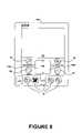
- FIG. 8illustrates a personal digital assistant in accordance with an embodiment of the present invention, whereas the personal digital assistant is in an inactive mode.
- FIG. 9illustrates a personal digital assistant in accordance with an embodiment of the present invention, whereas the personal digital assistant is in a normal operation mode.
- FIG. 10illustrates a flow chart diagram showing a method of configuring a personal digital assistant to recognize a user in accordance with an embodiment of the present invention.
- FIG. 11illustrates a flow chart diagram showing a method of authenticating a user and activating a personal digital assistant in response to a single action by the user in accordance with an embodiment of the present invention.
- the personal digital assistantis a pocket sized electronic organizer with the capability to store telephone numbers, addresses, daily appointments, and software that keeps track of business or personal data such as expenses, etc. Furthermore, the personal digital assistant also has the ability to connect to a personal computer, enabling the two devices to exchange updated information. Additionally, the personal digital assistant can also be connected to a modem, enabling it to have electronic mail (e-mail) capabilities over the Internet along with other Internet capabilities. Moreover, an advanced personal digital assistant can have Internet capabilities over a wireless communication interface (e.g., radio interface). In particular, the personal digital assistant can be used to browse Web pages located on the Internet.
- the personal digital assistantcan be coupled to a networking environment. It should be appreciated that embodiments of the present invention are well suited to operate within a wide variety of computer systems, some of which can be communicatively coupled to a networking environment.
- FIG. 1is a block diagram of a first exemplary network environment 50 including a personal digital assistant 100 on which the present invention can be practiced.
- the personal digital assistant 100is also known as a palmtop or palm-sized electronic system or computer system.
- the personal digital assistant 100has the ability to transmit and receive data and information over a wireless communication interface (e.g., a radio interface).
- the personal digital assistant 100is one exemplary computer system on which the present invention can operate.
- the present inventioncan operate on any other type of computer system.
- base station 32is both a transmitter and receiver base station which can be implemented by coupling it into an existing public telephone network 34 .
- base station 32enables the personal digital assistant 100 to communicate with a proxy server computer system 36 , which is coupled by wire 35 to the existing public telephone network 34 .
- proxy server computer system 36is coupled to the Internet 52 , thereby enabling the personal digital assistant 100 to communicate with the Internet 52 .
- one of the functions of proxy server 36is to perform operations over the Internet 52 on behalf of the personal digital assistant 100 .
- proxy server 36has a particular Internet address and acts as a proxy device for the personal digital assistant 100 over the Internet 52 .
- other communications networksmay be utilized in practicing the present invention.
- the data and information which are communicated between base station 32 and the personal digital assistant 100are a type of information and data that can conventionally be transferred and received over a public telephone wire network system.
- a wireless communication interfaceis utilized to communicate data and information between the personal digital assistant 100 and base station 32 .
- a wireless communication system in accordance with the present inventionis the Mobitex wireless communication system.
- FIG. 2illustrates a block diagram of a second exemplary network environment 51 including a personal digital assistant 100 on which the present invention can be practiced, whereas the personal digital assistant 100 is coupled to other computer systems and the Internet via a cradle device.
- Network system 51comprises a host computer system 56 which can either be a desktop computer system as shown, or, alternatively, can be a laptop computer system 58 .
- more than one host computer system 56can be used within network system 51 .
- Host computer systems 58 and 56are shown connected to a communication bus 54 , which in one embodiment can be a serial communication bus, but could be of any of a number of well known designs (e.g., a parallel bus, Ethernet Local Area Network (LAN), etc.).
- bus 54can provide communication with the Internet 52 using a number of well known protocols.
- bus 54is also coupled to a cradle 60 for receiving and initiating communication with the personal digital assistant 100 .
- Cradle 60provides an electrical and mechanical communication interface between bus 54 (and any device coupled to bus 54 ) and the personal digital assistant 100 for two-way communications.
- the personal digital assistant 100also contains a wireless infrared communication mechanism 64 for sending and receiving information from other devices.
- the personal digital assistant 100can be used in a network environment combining elements of networks 50 and 51 . That is, as will be seen below, the personal digital assistant 100 can include both a wireless infrared communication mechanism and a signal (e.g., radio) receiver/transmitter device.
- a wireless infrared communication mechanisme.g., Bluetooth
- a signale.g., radio
- FIG. 3is a perspective illustration of the top face 100 a of one embodiment of the personal digital assistant or palmtop computer system 100 .
- the top face 100 ahas a display screen 105 surrounded by a bezel or cover.
- a removable stylus 80is also shown.
- the display screen 105is a touch screen able to register contact between the screen and the tip of the stylus 80 .
- the stylus 80can be of any material to make contact with the display screen 105 .
- the top face 100 aalso has one or more dedicated and/or programmable buttons 75 for selecting information and causing the computer system to implement functions.
- the on/off button 95is also shown.
- a useris able to control specific functionality of the personal digital assistant 100 by using its plurality of buttons 75 (e.g., to invoke telephone/address data, calendar data, to-do-list data, memo pad data, etc.).
- the usercan utilize the stylus 80 in conjunction with the display screen 105 in order to cause the personal digital assistant 100 to perform a multitude of different functions.
- One such functionis the selecting of different functional operations of the personal digital assistant 100 , which are accomplished by touching stylus 80 to specific areas of display screen 105 .
- Another such functionis the entering of data into the exemplary personal digital assistant 100 .
- FIG. 3also illustrates a handwriting recognition pad 106 or “digitizer” containing two regions 106 a and 106 b .
- Region 106 ais for the drawing of alphabetic characters therein for automatic recognition
- region 106 bis for the drawing of numeric characters therein for automatic recognition.
- the stylus 80is used for stroking a character within one of the regions 106 a and 106 b .
- the stroke informationis then fed to an internal processor for automatic character recognition. Once characters are recognized, they are typically displayed on the screen 105 for verification and/or modification.
- FIG. 4illustrates the bottom side 100 b of one embodiment of the personal digital assistant or palmtop computer system 100 that can be used in accordance with various embodiments of the present invention.
- An extendible antenna 85is shown, and also a battery storage compartment door 90 is shown.
- the antenna 85enables the personal digital assistant 100 to be communicatively coupled to a network environment (as shown in FIG. 1 ) thereby enabling a user to communicate information with other electronic systems and electronic devices coupled to the network.
- a communication interface 180is also shown.
- the communication interface 180is a serial communication port, but could also alternatively be of any of a number of well-known communication standards and protocols (e.g., parallel, SCSI (small computer system interface), Firewire (IEEE 1394), Ethernet, etc.).
- FIG. 5is an exploded view of the personal digital assistant 100 .
- the personal digital assistant 100contains a front cover 210 having an outline of region 106 and holes 75 a for receiving buttons 75 b .
- a flat panel display 105(both liquid crystal display and touch screen) fits into front cover 210 . Any of a number of display technologies can be used, e.g., liquid crystal display (LCD), field emission display (FED), plasma, etc., for the flat panel display 105 .
- a battery 215provides electrical power.
- a contrast adjustment (potentiometer) 220is also shown, as well as an on/off button 95 .
- a flex circuit 230is shown along with a personal computer (PC) board 225 containing electronics and logic (e.g., memory, communication bus, processor, etc.) for implementing computer system functionality.
- the digitizer pad 106is also included in PC board 225 .
- a midframe 235is shown along with stylus 80 .
- Position-adjustable antenna 85is shown.
- Infrared communication mechanism 64(e.g., an infrared emitter and detector device) is for sending and receiving information from other similarly equipped devices (see FIG. 2 ).
- a signal (e.g., radio) receiver/transmitter device 108is also shown.
- the receiver/transmitter device 108is coupled to the antenna 85 and also coupled to communicate with the PC board 225 .
- the Mobitex wireless communication systemis used to provide two-way communication between the personal digital assistant 100 and other networked computers and/or the Internet via a proxy server (see FIG. 1 ).
- portions of the personal digital assistant 100are comprised of computer-readable and computer-executable instructions which reside, for example, in computer-readable media of the personal digital assistant 100 .
- FIG. 6is a block diagram of interior components of a personal digital assistant 100 in accordance with an embodiment of the present invention.
- the personal digital assistant 100includes an address/data bus 110 for communicating information, a central processor 101 coupled to the bus 110 for processing information and instructions, a volatile memory 102 (e.g., random access memory, static RAM, dynamic RAM, etc.) coupled to the bus 110 for storing information and instructions for the central processor 101 and a non-volatile memory 103 (e.g., read only memory, programmable ROM, flash memory, EPROM, EEPROM, etc.) coupled to the bus 110 for storing static information and instructions for the processor 101 .
- a volatile memory 102e.g., random access memory, static RAM, dynamic RAM, etc.
- non-volatile memory 103e.g., read only memory, programmable ROM, flash memory, EPROM, EEPROM, etc.
- the personal digital assistant 100also includes an optional data storage device 104 (e.g., memory card, hard drive, etc.) coupled with the bus 110 for storing information and instructions. Data storage device 104 can be removable. As described above, the personal digital assistant 100 also includes an electronic display device 105 coupled to the bus 110 for displaying information to the computer user.
- PC board 225can include the processor 101 , the bus 110 , the ROM 103 and the RAM 102 .
- the personal digital assistant 100also includes a signal transmitter/receiver device 108 which is coupled to bus 110 for providing a communication link between the personal digital assistant 100 and a network environment (e.g., network environments 50 and 51 of FIGS. 1 and 2 , respectively).
- signal transmitter/receiver device 108enables central processor unit 101 to communicate wirelessly with other electronic systems coupled to the network.
- signal transmitter/receiver device 108is coupled to antenna 85 ( FIG. 5 ) and provides the functionality to transmit and receive information over a wireless communication interface.
- the present embodiment of signal transmitter/receiver device 108is well-suited to be implemented in a wide variety of ways. For example, signal transmitter/receiver device 108 could be implemented as a modem.
- the personal digital assistant 100includes a communication circuit 109 coupled to bus 110 .
- Communication circuit 109includes an optional digital signal processor (DSP) 120 for processing data to be transmitted or data that are received via signal transmitter/receiver device 108 .
- DSPdigital signal processor
- some or all of the functions performed by DSP 120can be performed by processor 101 .
- an optional alphanumeric input device 106which in one implementation is a handwriting recognition pad 106 (“digitizer”) having regions 106 a and 106 b ( FIG. 3 ), for instance.
- Alphanumeric input device 106can communicate information and command selections to processor 101 .
- the personal digital assistant 100also includes an optional cursor control or directing device (on-screen cursor control 107 ) coupled to bus 110 for communicating user input information and command selections to processor 101 .
- on-screen cursor control device 107is a touch screen device incorporated with display device 105 .
- On-screen cursor control device 107is capable of registering a position on display device 105 where the stylus makes contact.
- the display device 105 utilized with the personal digital assistant 100may be a liquid crystal display device, a cathode ray tube (CRT), a field emission display device (also called a flat panel CRT) or other display device suitable for generating graphic images and alphanumeric characters recognizable to the user.
- display device 105is a flat panel display.
- the personal digital assistant 100includes a user verification device 117 which captures biometric data from a user.
- a user desiring to use or access the personal digital assistant 100initially interacts (e.g., presses, swipes, touches, etc.) upon the user verification device 117 .
- This initial interactioncauses the user verification device 117 to capture the biometric data from the user.
- the personal digital assistant 100verifies the biometric data. If the verification is successful, the personal digital assistant 100 powers-up from an inactive mode to a normal operation mode and enables the user to use the personal digital assistant 100 .
- the personal digital assistant 100can automatically launch an application program (e.g., a calendar program, an address-book program, a to-do-list program, a memo program, etc.).
- an application programe.g., a calendar program, an address-book program, a to-do-list program, a memo program, etc.
- FIG. 7is a perspective illustration of one embodiment of the cradle 60 for receiving the personal digital assistant or palmtop computer system 100 .
- Cradle 60includes a mechanical and electrical interface 260 for interfacing with communication interface 108 ( FIG. 4 ) of the personal digital assistant 100 when the personal digital assistant 100 is slid into the cradle 60 in an upright position.
- button 270can be pressed to initiate two-way communication between the personal digital assistant 100 and other computer systems or electronic devices coupled to serial communication 265 .
- FIG. 8illustrates a personal digital assistant 100 in accordance with an embodiment of the present invention, whereas the personal digital assistant 100 is in an inactive mode.
- the personal digital assistant 100In the inactive mode, the personal digital assistant 100 operates in a low-power state to conserve power while not in use.
- the personal digital assistant 100(1) authenticates a user desiring to use or access the personal digital assistant 100 and (2) powers-up from the inactive mode to a normal operation mode in response to a single action by the user.
- the security procedure of the present inventionintegrates a security routine and a power-up routine to avoid interfering with the primary function of the personal digital assistant 100 : providing quick access to frequently used data.
- the present inventionauthenticates and provides access to an authorized user in response to a single action upon the personal digital assistant 100 by a user desiring to use the personal digital assistant 100 . If the user desiring to use the personal digital assistant 100 is not an authorized user, the personal digital assistant 100 denies access.
- the personal digital assistant 100includes a display screen 105 , a handwriting recognition pad 106 or “digitizer” containing two regions 106 a and 106 b , a plurality of buttons 75 (e.g., to invoke telephone/address data, calendar data, to-do-list data, memo pad data, etc.), a plurality of application buttons 83 individually selectable with a stylus or finger, and a memory device 104 ( FIG. 6 ) for storing a reference template representing stored biometric data from an authorized user, whereas these features were described above. It should be understood that the personal digital assistant 100 can be configured with other features.
- the personal digital assistant 100includes a user verification device 117 which interacts with the user and facilitates authentication of the user.
- the user verification device 117includes a biometric sensor which scans and captures biometric data from the user.
- the biometric datacan be of any type. Examples of the biometric data include a thumbprint, a fingerprint, a magnetic characteristic, a color characteristic, a temperature characteristic, a geometric characteristic, and a combination thereof of the user.
- the user verification device 117is configured to capture biometric data in response to an action by the user desiring access to the computer system. For example, the user can activate the user verification device 117 by pressing, swiping, touching, or interacting with the user verification device 117 in any other manner.
- the user verification device 117can have a button-shape for receiving the finger, thumb, or any other part of the user.
- the captured biometric datacan be compressed, processed, and verified (e.g., compared with the reference template representing stored biometric data from an authorized user) by the user verification device 117 , the processor 101 ( FIG. 6 ) of the personal digital assistant 100 , any combination thereof, or in any other manner.
- a security procedure that uses biometric datais more secure than a security procedure that relies on a personal identification number (PIN), a password, or the user stroking particular characters on the handwriting recognition pad 106 with a stylus.
- PINpersonal identification number
- the particular type of biometric data captured by the user verification device 117affects the identification power of the security procedure of the present invention.
- each type of biometric datahas an false rejection rate (i.e., rate that an authorized user is denied access) and a false acceptance rate (i.e., rate that an unauthorized user is granted access).
- the type of biometric data selected for use in the user verification device 117can be tailored for the particular needs of the authorized user of the personal digital assistant 100 .
- a user desiring to access the personal digital assistant 100initially presses, swipes, touches, or interacts in any other manner with the user verification device 117 .
- the user verification device 117scans and captures the biometric data from the user.
- the personal digital assistant 100verifies the captured biometric data. If the verification is successful, the personal digital assistant 100 powers-up from the inactive mode to a normal operation mode as illustrated in FIG. 9 and enables the user to use the personal digital assistant 100 .
- the security procedure of the present inventionis a seamless and transparent operation from the user's perspective.
- the security procedure of the present inventionis convenient and protects the data stored in the personal digital assistant 100 in a manner that improves the user's experience with the personal digital assistant 100 since authentication and power-up are performed in response to a single action by the user.
- FIG. 9illustrates a personal digital assistant 100 in accordance with an embodiment of the present invention, whereas the personal digital assistant 100 is in a normal operation mode.
- the user verification device 117scans and captures the biometric data from the user. Furthermore, the personal digital assistant 100 verifies the captured biometric data. If the verification is successful, the personal digital assistant 100 powers-up from the inactive mode (as illustrated in FIG. 8 ) to a normal operation mode as illustrated in FIG. 9 and enables the user to use the personal digital assistant 100 .
- the personal digital assistant 100can automatically launch or invoke a preselected application program (e.g., a calendar program, an address-book program, a to-do-list program, a memo program, etc.) stored in the memory device 104 ( FIG. 6 ) of the personal digital assistant 100 .
- a memo programwas automatically launched.
- the usercan preconfigure the personal digital assistant 100 to launch any application program.
- the personal digital assistant 100can have a plurality of user verification devices 117 , each configured to cause the personal digital assistant 100 to launch an associated application program upon powering-up.
- FIG. 10illustrates a flow chart diagram showing a method 800 of configuring a personal digital assistant 100 to recognize a user in accordance with an embodiment of the present invention. Reference will be made to FIGS. 6 , 8 , and 9 .
- the method 800in accordance with an embodiment of the present invention begins.
- the personal digital assistant 100has the security capability described above.
- the user verification device 117has not scanned and captured a reference template representing the biometric data of an authorized user, whereas the reference template is stored in the memory device 104 or in any other location.
- the authorized userpowers-up the personal digital assistant 100 by pressing, swiping, touching, or interacting in any other manner with the user verification device 117 or any other component of the personal digital assistant 100 .
- the personal digital assistant 100invokes a security application.
- the security applicationconfigures the personal digital assistant 100 to recognize the authorized user.
- the useris prompted to interact with the biometric sensor 117 of the user verification device 117 .
- the biometric sensor 117scans and captures biometric data from the authorized user for generating a reference template which will be used during the security procedure of the present invention.
- the biometric datacan be of any type.
- the biometric datacan be captured from the authorized user's finger, thumb, hand, or any other body part.
- the reference templateis stored in the memory device 104 or in any other location. During subsequent user verification transactions pursuant to the security procedure of the present invention, the reference template is used to verify the identity of a user desiring to use or access the personal digital assistant 100 .
- the method 800 in accordance with an embodiment of the present inventionends.
- FIG. 11illustrates a flow chart diagram showing a method 900 of authenticating a user and activating a personal digital assistant 100 in response to a single action by the user in accordance with an embodiment of the present invention. Reference will be made to FIGS. 6 , 8 , and 9 .
- the method 900 in accordance with an embodiment of the present inventionbegins.
- the personal digital assistant 100has the security capability described above.
- the user verification device 117has scanned and captured a reference template representing the biometric data of an authorized user, whereas the reference template is stored in the memory device 104 or in any other location.
- the personal digital assistant 100is in an inactive mode.
- a user desiring to access or use the personal digital assistant 100presses the biometric sensor 117 of the user verification device 117 with his/her finger, thumb, hand, or any other part. Alternately, the user can touch, swipe, or interact with the biometric sensor 117 in any other manner.
- an interrupt to the processor 101 of the personal digital assistant 100is generated by the user verification device 117 .
- the interruptalerts the processor 101 that a user desires to access the personal digital assistant 100 .
- the personal digital assistant 100includes interrupt handling code to respond to the interrupt received from the user verification device 117 .
- the interrupt handling codedirects the personal digital assistant 100 to execute the security procedure of the present invention, including verifying the identity of the user.
- the personal digital assistant 100is sufficiently powered to execute the security procedure.
- the user verification device 117scans and captures biometric data from the user. In an embodiment, steps 915 and 920 are performed simultaneously.
- the user verification device 117transmits the captured biometric data to the processor 101 .
- the user verification device 117can be configured to verify the identity of the user.
- the processor 101compares the captured biometric data with the reference template.
- the processor 101determines whether the captured biometric data matches the reference template to verify the identity of the user. If there is no match, the method 900 continues to step 940 .
- the personal digital assistant 100denies the user access to the personal digital assistant 100 and maintains the personal digital assistant 100 in the inactive mode. In an embodiment, the personal digital assistant 100 shuts down for a time period after several consecutive user verification transaction failures.
- step 945the personal digital assistant 100 is powered-up from the inactive mode to a normal operation mode.
- the personal digital assistant 100grants the user access to the personal digital assistant 100 .
- the personal digital assistant 100automatically launches a preselected application program.
- the usercan be prompted to interact again with the user verification device 117 according to a programmable schedule.
- the user verification device 117captures new biometric data which is then processed and verified by the processor 101 to continue the user's access to the personal digital assistant 100 .
- the programmable schedulecan be configured in any manner. For example, the user may be prompted to reauthenticate every half hour of continuous use in the normal operation mode.
- step 960the method 900 in accordance with an embodiment of the present invention ends.
- the user verification device 117can be configured to capture either a complete set of biometric data or a sample set of biometric data from the user.
- a security procedure performed with the complete set of biometric datais more reliable and slower than a security procedure performed with a sample set of biometric data. Capturing the complete set of biometric data from the user is appropriate when a user initially requests access to the personal digital assistant 100 . Moreover, capturing the sample set of biometric data from the user is appropriate when reauthenticating the user during the normal operation mode.
- the personal digital assistant 100can be provided with criteria for determining when to capture a complete set of biometric data from a user rather than a sample set of biometric data from the user.
- portions of the present inventionmay be incorporated as computer instructions stored as computer program code on a computer-readable medium such as a magnetic disk, CD-ROM, and other media common in the art or that may yet be developed.
- aspects of the present inventioncan be implemented as an application, namely, a set of instructions (e.g., program code) which may, for example, be resident in the random access memory of a computer system.
- the set of instructionsmay be stored in another computer memory, for example, in a hard drive, or in a removable memory such as an optical disk (for eventual use in a CD-ROM) or floppy disk (for eventual use in a floppy disk drive), or downloaded via the Internet or other computer network.
Landscapes
- Engineering & Computer Science (AREA)
- Computer Security & Cryptography (AREA)
- Theoretical Computer Science (AREA)
- Computer Hardware Design (AREA)
- Software Systems (AREA)
- Physics & Mathematics (AREA)
- General Engineering & Computer Science (AREA)
- General Physics & Mathematics (AREA)
- Power Sources (AREA)
- Collating Specific Patterns (AREA)
Abstract
Description
Claims (21)
Priority Applications (2)
| Application Number | Priority Date | Filing Date | Title |
|---|---|---|---|
| US09/769,654US7124300B1 (en) | 2001-01-24 | 2001-01-24 | Handheld computer system configured to authenticate a user and power-up in response to a single action by the user |
| US11/520,873US8010798B1 (en) | 2001-01-24 | 2006-09-13 | Handheld computer system configured to authenticate a user and power-up in response to a single action by the user |
Applications Claiming Priority (1)
| Application Number | Priority Date | Filing Date | Title |
|---|---|---|---|
| US09/769,654US7124300B1 (en) | 2001-01-24 | 2001-01-24 | Handheld computer system configured to authenticate a user and power-up in response to a single action by the user |
Related Child Applications (1)
| Application Number | Title | Priority Date | Filing Date |
|---|---|---|---|
| US11/520,873ContinuationUS8010798B1 (en) | 2001-01-24 | 2006-09-13 | Handheld computer system configured to authenticate a user and power-up in response to a single action by the user |
Publications (1)
| Publication Number | Publication Date |
|---|---|
| US7124300B1true US7124300B1 (en) | 2006-10-17 |
Family
ID=37086059
Family Applications (2)
| Application Number | Title | Priority Date | Filing Date |
|---|---|---|---|
| US09/769,654Expired - LifetimeUS7124300B1 (en) | 2001-01-24 | 2001-01-24 | Handheld computer system configured to authenticate a user and power-up in response to a single action by the user |
| US11/520,873Expired - Fee RelatedUS8010798B1 (en) | 2001-01-24 | 2006-09-13 | Handheld computer system configured to authenticate a user and power-up in response to a single action by the user |
Family Applications After (1)
| Application Number | Title | Priority Date | Filing Date |
|---|---|---|---|
| US11/520,873Expired - Fee RelatedUS8010798B1 (en) | 2001-01-24 | 2006-09-13 | Handheld computer system configured to authenticate a user and power-up in response to a single action by the user |
Country Status (1)
| Country | Link |
|---|---|
| US (2) | US7124300B1 (en) |
Cited By (54)
| Publication number | Priority date | Publication date | Assignee | Title |
|---|---|---|---|---|
| US20020001400A1 (en)* | 2000-04-26 | 2002-01-03 | Shunpei Yamazaki | System for identifying an individual, a method for identifying an individual or a business method |
| US20050255840A1 (en)* | 2004-05-13 | 2005-11-17 | Markham Thomas R | Authenticating wireless phone system |
| US20070005988A1 (en)* | 2005-06-29 | 2007-01-04 | Microsoft Corporation | Multimodal authentication |
| US20070240202A1 (en)* | 2006-04-07 | 2007-10-11 | Zing Systems, Inc. | Authentication service for facilitating access to services |
| US20080016367A1 (en)* | 2006-06-23 | 2008-01-17 | Yoshifumi Tanada | Personal data management system and nonvolatile memory card |
| US20090158423A1 (en)* | 2007-12-14 | 2009-06-18 | Symbol Technologies, Inc. | Locking mobile device cradle |
| US20090283588A1 (en)* | 2006-04-26 | 2009-11-19 | International Business Machines Corporation | Verification of a Biometric Identification |
| US7626582B1 (en) | 2000-03-09 | 2009-12-01 | Palm, Inc. | Method and apparatus for automatic power-up and power-down of an electronic device |
| US20100041965A1 (en)* | 2008-08-14 | 2010-02-18 | National Taiwan University | Handheld Sleep Assistant Device and Method |
| US20100138914A1 (en)* | 2008-12-01 | 2010-06-03 | Research In Motion Limited | System and method of providing biometric quick launch |
| US8010798B1 (en)* | 2001-01-24 | 2011-08-30 | Hewlett-Packard Development Company, L.P. | Handheld computer system configured to authenticate a user and power-up in response to a single action by the user |
| US8085992B1 (en) | 2011-01-20 | 2011-12-27 | Daon Holdings Limited | Methods and systems for capturing biometric data |
| US8219495B2 (en) | 2000-02-23 | 2012-07-10 | Sony Corporation | Method of using personal device with internal biometric in conducting transactions over a network |
| US8286256B2 (en)* | 2001-03-01 | 2012-10-09 | Sony Corporation | Method and system for restricted biometric access to content of packaged media |
| US20130133042A1 (en)* | 2001-09-28 | 2013-05-23 | Imprivata, Inc. | Biometric authentication |
| US20140006765A1 (en)* | 2012-06-27 | 2014-01-02 | Kabushiki Kaisha Toshiba | Information processing apparatus and start-up control method |
| US20140152435A1 (en)* | 2003-02-17 | 2014-06-05 | Raymond Douglas | Tracking and monitoring apparatus and system |
| US8943580B2 (en) | 2007-09-24 | 2015-01-27 | Apple Inc. | Embedded authentication systems in an electronic device |
| US20150088514A1 (en)* | 2013-09-25 | 2015-03-26 | Rawles Llc | In-Call Virtual Assistants |
| US9223948B2 (en) | 2011-11-01 | 2015-12-29 | Blackberry Limited | Combined passcode and activity launch modifier |
| US9342674B2 (en) | 2003-05-30 | 2016-05-17 | Apple Inc. | Man-machine interface for controlling access to electronic devices |
| US9386519B1 (en)* | 2009-04-16 | 2016-07-05 | Marvell International Ltd. | Method and apparatus for transitioning a first processor of an access point between power modes based on communication between a client device and a second processor of the access point |
| US9519820B2 (en) | 2011-01-20 | 2016-12-13 | Daon Holdings Limited | Methods and systems for authenticating users |
| US20170092278A1 (en)* | 2015-09-30 | 2017-03-30 | Apple Inc. | Speaker recognition |
| US20170272421A1 (en)* | 2009-09-21 | 2017-09-21 | Convergence Biometrics, LLC | Systems and methods for securely monitoring an individual |
| US9847999B2 (en) | 2016-05-19 | 2017-12-19 | Apple Inc. | User interface for a device requesting remote authorization |
| US9898642B2 (en) | 2013-09-09 | 2018-02-20 | Apple Inc. | Device, method, and graphical user interface for manipulating user interfaces based on fingerprint sensor inputs |
| US10043516B2 (en) | 2016-09-23 | 2018-08-07 | Apple Inc. | Intelligent automated assistant |
| US10142835B2 (en) | 2011-09-29 | 2018-11-27 | Apple Inc. | Authentication with secondary approver |
| US10356243B2 (en) | 2015-06-05 | 2019-07-16 | Apple Inc. | Virtual assistant aided communication with 3rd party service in a communication session |
| US10395128B2 (en) | 2017-09-09 | 2019-08-27 | Apple Inc. | Implementation of biometric authentication |
| US10410637B2 (en) | 2017-05-12 | 2019-09-10 | Apple Inc. | User-specific acoustic models |
| US10438205B2 (en) | 2014-05-29 | 2019-10-08 | Apple Inc. | User interface for payments |
| US10482874B2 (en) | 2017-05-15 | 2019-11-19 | Apple Inc. | Hierarchical belief states for digital assistants |
| US10484384B2 (en) | 2011-09-29 | 2019-11-19 | Apple Inc. | Indirect authentication |
| US10510097B2 (en) | 2011-10-19 | 2019-12-17 | Firstface Co., Ltd. | Activating display and performing additional function in mobile terminal with one-time user input |
| US10521579B2 (en) | 2017-09-09 | 2019-12-31 | Apple Inc. | Implementation of biometric authentication |
| US10534899B2 (en) | 2017-08-24 | 2020-01-14 | Blackberry Limited | Utilizing inputs for accessing devices |
| US10567477B2 (en) | 2015-03-08 | 2020-02-18 | Apple Inc. | Virtual assistant continuity |
| US10755703B2 (en) | 2017-05-11 | 2020-08-25 | Apple Inc. | Offline personal assistant |
| US10791176B2 (en) | 2017-05-12 | 2020-09-29 | Apple Inc. | Synchronization and task delegation of a digital assistant |
| US10810274B2 (en) | 2017-05-15 | 2020-10-20 | Apple Inc. | Optimizing dialogue policy decisions for digital assistants using implicit feedback |
| US10860096B2 (en) | 2018-09-28 | 2020-12-08 | Apple Inc. | Device control using gaze information |
| US11073892B2 (en)* | 2018-06-14 | 2021-07-27 | Lenovo (Singapore) Pte. Ltd. | Processing capacity and heat management of an information processing device |
| US11100349B2 (en) | 2018-09-28 | 2021-08-24 | Apple Inc. | Audio assisted enrollment |
| US11170085B2 (en) | 2018-06-03 | 2021-11-09 | Apple Inc. | Implementation of biometric authentication |
| US11209961B2 (en) | 2012-05-18 | 2021-12-28 | Apple Inc. | Device, method, and graphical user interface for manipulating user interfaces based on fingerprint sensor inputs |
| US11217255B2 (en) | 2017-05-16 | 2022-01-04 | Apple Inc. | Far-field extension for digital assistant services |
| US11676373B2 (en) | 2008-01-03 | 2023-06-13 | Apple Inc. | Personal computing device control using face detection and recognition |
| US12079458B2 (en) | 2016-09-23 | 2024-09-03 | Apple Inc. | Image data for enhanced user interactions |
| US12099586B2 (en) | 2021-01-25 | 2024-09-24 | Apple Inc. | Implementation of biometric authentication |
| US12210603B2 (en) | 2021-03-04 | 2025-01-28 | Apple Inc. | User interface for enrolling a biometric feature |
| US12216754B2 (en) | 2021-05-10 | 2025-02-04 | Apple Inc. | User interfaces for authenticating to perform secure operations |
| US12262111B2 (en) | 2011-06-05 | 2025-03-25 | Apple Inc. | Device, method, and graphical user interface for accessing an application in a locked device |
Families Citing this family (6)
| Publication number | Priority date | Publication date | Assignee | Title |
|---|---|---|---|---|
| US20100321159A1 (en)* | 2009-06-18 | 2010-12-23 | Authentec, Inc. | Touch based data communication using biometric finger sensor and associated methods |
| US8671454B2 (en)* | 2010-11-04 | 2014-03-11 | Verifone, Inc. | System for secure web-prompt processing on point of sale devices |
| US9582127B2 (en) | 2014-04-04 | 2017-02-28 | Synaptics Incorporated | Large feature biometrics using capacitive touchscreens |
| US10424407B2 (en)* | 2016-08-10 | 2019-09-24 | Elwha Llc | Systems and methods for individual identification and authorization utilizing conformable electronics |
| WO2020009905A1 (en)* | 2018-07-06 | 2020-01-09 | Elwha Llc | Systems and methods for individual identification and authorization utilizing conformable electronics |
| NL2025868B1 (en) | 2020-06-19 | 2022-02-17 | Microsoft Technology Licensing Llc | Power key and fingerprint reader |
Citations (4)
| Publication number | Priority date | Publication date | Assignee | Title |
|---|---|---|---|---|
| US5900875A (en)* | 1997-01-29 | 1999-05-04 | 3Com Corporation | Method and apparatus for interacting with a portable computer system |
| US6016476A (en)* | 1997-08-11 | 2000-01-18 | International Business Machines Corporation | Portable information and transaction processing system and method utilizing biometric authorization and digital certificate security |
| US20020089410A1 (en)* | 2000-11-13 | 2002-07-11 | Janiak Martin J. | Biometric authentication device for use with a personal digital assistant |
| US6434403B1 (en)* | 1999-02-19 | 2002-08-13 | Bodycom, Inc. | Personal digital assistant with wireless telephone |
Family Cites Families (7)
| Publication number | Priority date | Publication date | Assignee | Title |
|---|---|---|---|---|
| US5796827A (en)* | 1996-11-14 | 1998-08-18 | International Business Machines Corporation | System and method for near-field human-body coupling for encrypted communication with identification cards |
| US6101608A (en)* | 1997-02-20 | 2000-08-08 | Compaq Computer Corporation | Method and apparatus for secure remote wake-up of a computer over a network |
| US5892901A (en)* | 1997-06-10 | 1999-04-06 | The United States Of America As Represented By The Secretary Of The Navy | Secure identification system |
| US6618806B1 (en)* | 1998-04-01 | 2003-09-09 | Saflink Corporation | System and method for authenticating users in a computer network |
| WO2001024123A1 (en)* | 1999-09-28 | 2001-04-05 | Chameleon Network Inc. | Portable electronic authorization system and associated method |
| US7124300B1 (en)* | 2001-01-24 | 2006-10-17 | Palm, Inc. | Handheld computer system configured to authenticate a user and power-up in response to a single action by the user |
| WO2002062024A2 (en)* | 2001-01-30 | 2002-08-08 | Broadcom Corporation | Method for adding a new device to a wireless network |
- 2001
- 2001-01-24USUS09/769,654patent/US7124300B1/ennot_activeExpired - Lifetime
- 2006
- 2006-09-13USUS11/520,873patent/US8010798B1/ennot_activeExpired - Fee Related
Patent Citations (4)
| Publication number | Priority date | Publication date | Assignee | Title |
|---|---|---|---|---|
| US5900875A (en)* | 1997-01-29 | 1999-05-04 | 3Com Corporation | Method and apparatus for interacting with a portable computer system |
| US6016476A (en)* | 1997-08-11 | 2000-01-18 | International Business Machines Corporation | Portable information and transaction processing system and method utilizing biometric authorization and digital certificate security |
| US6434403B1 (en)* | 1999-02-19 | 2002-08-13 | Bodycom, Inc. | Personal digital assistant with wireless telephone |
| US20020089410A1 (en)* | 2000-11-13 | 2002-07-11 | Janiak Martin J. | Biometric authentication device for use with a personal digital assistant |
Cited By (133)
| Publication number | Priority date | Publication date | Assignee | Title |
|---|---|---|---|---|
| US8219495B2 (en) | 2000-02-23 | 2012-07-10 | Sony Corporation | Method of using personal device with internal biometric in conducting transactions over a network |
| US8838502B2 (en) | 2000-02-23 | 2014-09-16 | Sony Corporation | Method of using personal device with internal biometric in conducting transactions over a network |
| US7626582B1 (en) | 2000-03-09 | 2009-12-01 | Palm, Inc. | Method and apparatus for automatic power-up and power-down of an electronic device |
| US7836491B2 (en)* | 2000-04-26 | 2010-11-16 | Semiconductor Energy Laboratory Co., Ltd. | System for identifying an individual, a method for identifying an individual or a business method |
| US20110035798A1 (en)* | 2000-04-26 | 2011-02-10 | Semiconductor Energy Laboratory Co., Ltd. | System for identifying an individual, a method for identifying an individual or a business method |
| US20020001400A1 (en)* | 2000-04-26 | 2002-01-03 | Shunpei Yamazaki | System for identifying an individual, a method for identifying an individual or a business method |
| US8010798B1 (en)* | 2001-01-24 | 2011-08-30 | Hewlett-Packard Development Company, L.P. | Handheld computer system configured to authenticate a user and power-up in response to a single action by the user |
| US8286256B2 (en)* | 2001-03-01 | 2012-10-09 | Sony Corporation | Method and system for restricted biometric access to content of packaged media |
| US20130133042A1 (en)* | 2001-09-28 | 2013-05-23 | Imprivata, Inc. | Biometric authentication |
| US9898915B2 (en)* | 2003-02-17 | 2018-02-20 | Kinderguard Limited | Tracking and monitoring apparatus and system |
| US20140152435A1 (en)* | 2003-02-17 | 2014-06-05 | Raymond Douglas | Tracking and monitoring apparatus and system |
| US9342674B2 (en) | 2003-05-30 | 2016-05-17 | Apple Inc. | Man-machine interface for controlling access to electronic devices |
| US20050255840A1 (en)* | 2004-05-13 | 2005-11-17 | Markham Thomas R | Authenticating wireless phone system |
| US20070005988A1 (en)* | 2005-06-29 | 2007-01-04 | Microsoft Corporation | Multimodal authentication |
| US8079079B2 (en)* | 2005-06-29 | 2011-12-13 | Microsoft Corporation | Multimodal authentication |
| US7886343B2 (en)* | 2006-04-07 | 2011-02-08 | Dell Products L.P. | Authentication service for facilitating access to services |
| US20070240202A1 (en)* | 2006-04-07 | 2007-10-11 | Zing Systems, Inc. | Authentication service for facilitating access to services |
| US7878412B2 (en)* | 2006-04-26 | 2011-02-01 | International Business Machines Corporation | Verification of a biometric identification |
| US20090283588A1 (en)* | 2006-04-26 | 2009-11-19 | International Business Machines Corporation | Verification of a Biometric Identification |
| US7987498B2 (en) | 2006-06-23 | 2011-07-26 | Semiconductor Energy Laboratory Co., Ltd. | Personal data management system and nonvolatile memory card |
| US20080016367A1 (en)* | 2006-06-23 | 2008-01-17 | Yoshifumi Tanada | Personal data management system and nonvolatile memory card |
| US9304624B2 (en) | 2007-09-24 | 2016-04-05 | Apple Inc. | Embedded authentication systems in an electronic device |
| US9134896B2 (en) | 2007-09-24 | 2015-09-15 | Apple Inc. | Embedded authentication systems in an electronic device |
| US10956550B2 (en) | 2007-09-24 | 2021-03-23 | Apple Inc. | Embedded authentication systems in an electronic device |
| US11468155B2 (en) | 2007-09-24 | 2022-10-11 | Apple Inc. | Embedded authentication systems in an electronic device |
| US9329771B2 (en) | 2007-09-24 | 2016-05-03 | Apple Inc | Embedded authentication systems in an electronic device |
| US9495531B2 (en) | 2007-09-24 | 2016-11-15 | Apple Inc. | Embedded authentication systems in an electronic device |
| US8943580B2 (en) | 2007-09-24 | 2015-01-27 | Apple Inc. | Embedded authentication systems in an electronic device |
| US9953152B2 (en) | 2007-09-24 | 2018-04-24 | Apple Inc. | Embedded authentication systems in an electronic device |
| US9038167B2 (en) | 2007-09-24 | 2015-05-19 | Apple Inc. | Embedded authentication systems in an electronic device |
| US9274647B2 (en) | 2007-09-24 | 2016-03-01 | Apple Inc. | Embedded authentication systems in an electronic device |
| US9128601B2 (en) | 2007-09-24 | 2015-09-08 | Apple Inc. | Embedded authentication systems in an electronic device |
| US9250795B2 (en) | 2007-09-24 | 2016-02-02 | Apple Inc. | Embedded authentication systems in an electronic device |
| US9519771B2 (en) | 2007-09-24 | 2016-12-13 | Apple Inc. | Embedded authentication systems in an electronic device |
| US10275585B2 (en) | 2007-09-24 | 2019-04-30 | Apple Inc. | Embedded authentication systems in an electronic device |
| US20090158423A1 (en)* | 2007-12-14 | 2009-06-18 | Symbol Technologies, Inc. | Locking mobile device cradle |
| US12406490B2 (en) | 2008-01-03 | 2025-09-02 | Apple Inc. | Personal computing device control using face detection and recognition |
| US11676373B2 (en) | 2008-01-03 | 2023-06-13 | Apple Inc. | Personal computing device control using face detection and recognition |
| TWI405559B (en)* | 2008-08-14 | 2013-08-21 | Univ Nat Taiwan | Handheld sleep assistant device and method |
| US20100041965A1 (en)* | 2008-08-14 | 2010-02-18 | National Taiwan University | Handheld Sleep Assistant Device and Method |
| US20130007876A1 (en)* | 2008-12-01 | 2013-01-03 | Research In Motion Limited | System and method of providing biometric quick launch |
| US20100138914A1 (en)* | 2008-12-01 | 2010-06-03 | Research In Motion Limited | System and method of providing biometric quick launch |
| US9386519B1 (en)* | 2009-04-16 | 2016-07-05 | Marvell International Ltd. | Method and apparatus for transitioning a first processor of an access point between power modes based on communication between a client device and a second processor of the access point |
| US10554648B1 (en) | 2009-09-21 | 2020-02-04 | Halo Wearables, Llc | Calibration of a wearable medical device |
| US10911427B1 (en) | 2009-09-21 | 2021-02-02 | Halo Wearables, Llc | Reconfiguration of a wearable medical device |
| US20170272421A1 (en)* | 2009-09-21 | 2017-09-21 | Convergence Biometrics, LLC | Systems and methods for securely monitoring an individual |
| US10320767B2 (en)* | 2009-09-21 | 2019-06-11 | Convergence Biometrics, LLC | Systems and methods for securely monitoring an individual |
| US9519820B2 (en) | 2011-01-20 | 2016-12-13 | Daon Holdings Limited | Methods and systems for authenticating users |
| US9519821B2 (en) | 2011-01-20 | 2016-12-13 | Daon Holdings Limited | Methods and systems for capturing biometric data |
| US9112858B2 (en) | 2011-01-20 | 2015-08-18 | Daon Holdings Limited | Methods and systems for capturing biometric data |
| US9679193B2 (en) | 2011-01-20 | 2017-06-13 | Daon Holdings Limited | Methods and systems for capturing biometric data |
| US9519818B2 (en) | 2011-01-20 | 2016-12-13 | Daon Holdings Limited | Methods and systems for capturing biometric data |
| US8085992B1 (en) | 2011-01-20 | 2011-12-27 | Daon Holdings Limited | Methods and systems for capturing biometric data |
| US9400915B2 (en) | 2011-01-20 | 2016-07-26 | Daon Holdings Limited | Methods and systems for capturing biometric data |
| US8548206B2 (en) | 2011-01-20 | 2013-10-01 | Daon Holdings Limited | Methods and systems for capturing biometric data |
| US9298999B2 (en) | 2011-01-20 | 2016-03-29 | Daon Holdings Limited | Methods and systems for capturing biometric data |
| US9990528B2 (en) | 2011-01-20 | 2018-06-05 | Daon Holdings Limited | Methods and systems for capturing biometric data |
| US10607054B2 (en) | 2011-01-20 | 2020-03-31 | Daon Holdings Limited | Methods and systems for capturing biometric data |
| US9202102B1 (en) | 2011-01-20 | 2015-12-01 | Daon Holdings Limited | Methods and systems for capturing biometric data |
| US10235550B2 (en) | 2011-01-20 | 2019-03-19 | Daon Holdings Limited | Methods and systems for capturing biometric data |
| US12262111B2 (en) | 2011-06-05 | 2025-03-25 | Apple Inc. | Device, method, and graphical user interface for accessing an application in a locked device |
| US10419933B2 (en) | 2011-09-29 | 2019-09-17 | Apple Inc. | Authentication with secondary approver |
| US10142835B2 (en) | 2011-09-29 | 2018-11-27 | Apple Inc. | Authentication with secondary approver |
| US10484384B2 (en) | 2011-09-29 | 2019-11-19 | Apple Inc. | Indirect authentication |
| US11200309B2 (en) | 2011-09-29 | 2021-12-14 | Apple Inc. | Authentication with secondary approver |
| US11755712B2 (en) | 2011-09-29 | 2023-09-12 | Apple Inc. | Authentication with secondary approver |
| US10516997B2 (en) | 2011-09-29 | 2019-12-24 | Apple Inc. | Authentication with secondary approver |
| US10896442B2 (en) | 2011-10-19 | 2021-01-19 | Firstface Co., Ltd. | Activating display and performing additional function in mobile terminal with one-time user input |
| US10510097B2 (en) | 2011-10-19 | 2019-12-17 | Firstface Co., Ltd. | Activating display and performing additional function in mobile terminal with one-time user input |
| US11551263B2 (en) | 2011-10-19 | 2023-01-10 | Firstface Co., Ltd. | Activating display and performing additional function in mobile terminal with one-time user input |
| US12159299B2 (en) | 2011-10-19 | 2024-12-03 | Firstface Co., Ltd. | Activating display and performing additional function in mobile terminal with one-time user input |
| US9223948B2 (en) | 2011-11-01 | 2015-12-29 | Blackberry Limited | Combined passcode and activity launch modifier |
| US11209961B2 (en) | 2012-05-18 | 2021-12-28 | Apple Inc. | Device, method, and graphical user interface for manipulating user interfaces based on fingerprint sensor inputs |
| US11989394B2 (en) | 2012-05-18 | 2024-05-21 | Apple Inc. | Device, method, and graphical user interface for manipulating user interfaces based on fingerprint sensor inputs |
| US20140006765A1 (en)* | 2012-06-27 | 2014-01-02 | Kabushiki Kaisha Toshiba | Information processing apparatus and start-up control method |
| US9177151B2 (en)* | 2012-06-27 | 2015-11-03 | Kabushiki Kaisha Toshiba | Operating speed control of a processor at the time of authentication before an operating system is started |
| US11494046B2 (en) | 2013-09-09 | 2022-11-08 | Apple Inc. | Device, method, and graphical user interface for manipulating user interfaces based on unlock inputs |
| US10055634B2 (en) | 2013-09-09 | 2018-08-21 | Apple Inc. | Device, method, and graphical user interface for manipulating user interfaces based on fingerprint sensor inputs |
| US11768575B2 (en) | 2013-09-09 | 2023-09-26 | Apple Inc. | Device, method, and graphical user interface for manipulating user interfaces based on unlock inputs |
| US10410035B2 (en) | 2013-09-09 | 2019-09-10 | Apple Inc. | Device, method, and graphical user interface for manipulating user interfaces based on fingerprint sensor inputs |
| US12314527B2 (en) | 2013-09-09 | 2025-05-27 | Apple Inc. | Device, method, and graphical user interface for manipulating user interfaces based on unlock inputs |
| US9898642B2 (en) | 2013-09-09 | 2018-02-20 | Apple Inc. | Device, method, and graphical user interface for manipulating user interfaces based on fingerprint sensor inputs |
| US10372963B2 (en) | 2013-09-09 | 2019-08-06 | Apple Inc. | Device, method, and graphical user interface for manipulating user interfaces based on fingerprint sensor inputs |
| US10262182B2 (en) | 2013-09-09 | 2019-04-16 | Apple Inc. | Device, method, and graphical user interface for manipulating user interfaces based on unlock inputs |
| US10803281B2 (en) | 2013-09-09 | 2020-10-13 | Apple Inc. | Device, method, and graphical user interface for manipulating user interfaces based on fingerprint sensor inputs |
| US11287942B2 (en) | 2013-09-09 | 2022-03-29 | Apple Inc. | Device, method, and graphical user interface for manipulating user interfaces |
| US20150088514A1 (en)* | 2013-09-25 | 2015-03-26 | Rawles Llc | In-Call Virtual Assistants |
| US10134395B2 (en)* | 2013-09-25 | 2018-11-20 | Amazon Technologies, Inc. | In-call virtual assistants |
| US10748153B2 (en) | 2014-05-29 | 2020-08-18 | Apple Inc. | User interface for payments |
| US10796309B2 (en) | 2014-05-29 | 2020-10-06 | Apple Inc. | User interface for payments |
| US10438205B2 (en) | 2014-05-29 | 2019-10-08 | Apple Inc. | User interface for payments |
| US10977651B2 (en) | 2014-05-29 | 2021-04-13 | Apple Inc. | User interface for payments |
| US11836725B2 (en) | 2014-05-29 | 2023-12-05 | Apple Inc. | User interface for payments |
| US10902424B2 (en) | 2014-05-29 | 2021-01-26 | Apple Inc. | User interface for payments |
| US10567477B2 (en) | 2015-03-08 | 2020-02-18 | Apple Inc. | Virtual assistant continuity |
| US10356243B2 (en) | 2015-06-05 | 2019-07-16 | Apple Inc. | Virtual assistant aided communication with 3rd party service in a communication session |
| US20170092278A1 (en)* | 2015-09-30 | 2017-03-30 | Apple Inc. | Speaker recognition |
| US10334054B2 (en) | 2016-05-19 | 2019-06-25 | Apple Inc. | User interface for a device requesting remote authorization |
| US10749967B2 (en) | 2016-05-19 | 2020-08-18 | Apple Inc. | User interface for remote authorization |
| US9847999B2 (en) | 2016-05-19 | 2017-12-19 | Apple Inc. | User interface for a device requesting remote authorization |
| US11206309B2 (en) | 2016-05-19 | 2021-12-21 | Apple Inc. | User interface for remote authorization |
| US12079458B2 (en) | 2016-09-23 | 2024-09-03 | Apple Inc. | Image data for enhanced user interactions |
| US10043516B2 (en) | 2016-09-23 | 2018-08-07 | Apple Inc. | Intelligent automated assistant |
| US10553215B2 (en) | 2016-09-23 | 2020-02-04 | Apple Inc. | Intelligent automated assistant |
| US10755703B2 (en) | 2017-05-11 | 2020-08-25 | Apple Inc. | Offline personal assistant |
| US10791176B2 (en) | 2017-05-12 | 2020-09-29 | Apple Inc. | Synchronization and task delegation of a digital assistant |
| US10410637B2 (en) | 2017-05-12 | 2019-09-10 | Apple Inc. | User-specific acoustic models |
| US11405466B2 (en) | 2017-05-12 | 2022-08-02 | Apple Inc. | Synchronization and task delegation of a digital assistant |
| US10482874B2 (en) | 2017-05-15 | 2019-11-19 | Apple Inc. | Hierarchical belief states for digital assistants |
| US10810274B2 (en) | 2017-05-15 | 2020-10-20 | Apple Inc. | Optimizing dialogue policy decisions for digital assistants using implicit feedback |
| US11217255B2 (en) | 2017-05-16 | 2022-01-04 | Apple Inc. | Far-field extension for digital assistant services |
| US10534899B2 (en) | 2017-08-24 | 2020-01-14 | Blackberry Limited | Utilizing inputs for accessing devices |
| US10521579B2 (en) | 2017-09-09 | 2019-12-31 | Apple Inc. | Implementation of biometric authentication |
| US10395128B2 (en) | 2017-09-09 | 2019-08-27 | Apple Inc. | Implementation of biometric authentication |
| US10872256B2 (en) | 2017-09-09 | 2020-12-22 | Apple Inc. | Implementation of biometric authentication |
| US11393258B2 (en) | 2017-09-09 | 2022-07-19 | Apple Inc. | Implementation of biometric authentication |
| US11765163B2 (en) | 2017-09-09 | 2023-09-19 | Apple Inc. | Implementation of biometric authentication |
| US11386189B2 (en) | 2017-09-09 | 2022-07-12 | Apple Inc. | Implementation of biometric authentication |
| US10783227B2 (en) | 2017-09-09 | 2020-09-22 | Apple Inc. | Implementation of biometric authentication |
| US10410076B2 (en) | 2017-09-09 | 2019-09-10 | Apple Inc. | Implementation of biometric authentication |
| US11928200B2 (en) | 2018-06-03 | 2024-03-12 | Apple Inc. | Implementation of biometric authentication |
| US11170085B2 (en) | 2018-06-03 | 2021-11-09 | Apple Inc. | Implementation of biometric authentication |
| US12189748B2 (en) | 2018-06-03 | 2025-01-07 | Apple Inc. | Implementation of biometric authentication |
| US11073892B2 (en)* | 2018-06-14 | 2021-07-27 | Lenovo (Singapore) Pte. Ltd. | Processing capacity and heat management of an information processing device |
| US11100349B2 (en) | 2018-09-28 | 2021-08-24 | Apple Inc. | Audio assisted enrollment |
| US11809784B2 (en) | 2018-09-28 | 2023-11-07 | Apple Inc. | Audio assisted enrollment |
| US11619991B2 (en) | 2018-09-28 | 2023-04-04 | Apple Inc. | Device control using gaze information |
| US12105874B2 (en) | 2018-09-28 | 2024-10-01 | Apple Inc. | Device control using gaze information |
| US12124770B2 (en) | 2018-09-28 | 2024-10-22 | Apple Inc. | Audio assisted enrollment |
| US10860096B2 (en) | 2018-09-28 | 2020-12-08 | Apple Inc. | Device control using gaze information |
| US12099586B2 (en) | 2021-01-25 | 2024-09-24 | Apple Inc. | Implementation of biometric authentication |
| US12210603B2 (en) | 2021-03-04 | 2025-01-28 | Apple Inc. | User interface for enrolling a biometric feature |
| US12216754B2 (en) | 2021-05-10 | 2025-02-04 | Apple Inc. | User interfaces for authenticating to perform secure operations |
Also Published As
| Publication number | Publication date |
|---|---|
| US8010798B1 (en) | 2011-08-30 |
Similar Documents
| Publication | Publication Date | Title |
|---|---|---|
| US7124300B1 (en) | Handheld computer system configured to authenticate a user and power-up in response to a single action by the user | |
| US7774613B2 (en) | Security technique for controlling access to a network by a wireless device | |
| Jansen | Authenticating users on handheld devices | |
| US8001288B2 (en) | Method and system for enabling personal digital assistants and protecting stored private data | |
| CN107066862B (en) | Embedded Authentication Systems in Electronic Devices | |
| US7673149B2 (en) | Identification and/or authentication method | |
| US7382904B2 (en) | Security system and security method using fingerprints | |
| USRE43577E1 (en) | Swapping a nonoperational networked electronic system for an operational networked electronic system | |
| US7559083B2 (en) | Method and apparatus for generating secured attention sequence | |
| US20130007876A1 (en) | System and method of providing biometric quick launch | |
| US20030172283A1 (en) | Biometric characteristic-enabled remote control device | |
| US7711785B2 (en) | System for using email message to transmit a command to remotely control a computer resource | |
| EP3699789A1 (en) | Method and device for security verification and mobile terminal | |
| CN107223254A (en) | The biological characteristic run in the background is set | |
| JP2001092554A (en) | Information processor | |
| US20030040339A1 (en) | Method and system for accessing functions of a portable information appliance | |
| CN108985034A (en) | A kind of unlocking method and terminal device | |
| US8416705B2 (en) | User profile or user account association with multiple computers | |
| EP2192519B1 (en) | System and method of providing biometric quick launch | |
| EP1782155B1 (en) | Methods and apparatuses for automatically selecting a profile | |
| US20140040986A1 (en) | Protocol to Prevent Replay Attacks on Secured Wireless Transactions | |
| US6810493B1 (en) | Graceful recovery from and avoidance of crashes due to notification of third party applications | |
| JP3687569B2 (en) | Portable display device and program | |
| US20040049686A1 (en) | Fingerprint identification applied data storage system and method | |
| JP2002334065A (en) | Information processing device using portable operators |
Legal Events
| Date | Code | Title | Description |
|---|---|---|---|
| AS | Assignment | Owner name:PALM, INC., CALIFORNIA Free format text:ASSIGNMENT OF ASSIGNORS INTEREST;ASSIGNOR:LEMKE, STEVE;REEL/FRAME:011714/0058 Effective date:20010326 | |
| STCF | Information on status: patent grant | Free format text:PATENTED CASE | |
| FEPP | Fee payment procedure | Free format text:PAYOR NUMBER ASSIGNED (ORIGINAL EVENT CODE: ASPN); ENTITY STATUS OF PATENT OWNER: LARGE ENTITY | |
| AS | Assignment | Owner name:JPMORGAN CHASE BANK, N.A., NEW YORK Free format text:SECURITY AGREEMENT;ASSIGNOR:PALM, INC.;REEL/FRAME:020317/0256 Effective date:20071024 | |
| FPAY | Fee payment | Year of fee payment:4 | |
| AS | Assignment | Owner name:PALM, INC., CALIFORNIA Free format text:RELEASE BY SECURED PARTY;ASSIGNOR:JPMORGAN CHASE BANK, N.A., AS ADMINISTRATIVE AGENT;REEL/FRAME:024630/0474 Effective date:20100701 | |
| AS | Assignment | Owner name:HEWLETT-PACKARD DEVELOPMENT COMPANY, L.P., TEXAS Free format text:ASSIGNMENT OF ASSIGNORS INTEREST;ASSIGNOR:PALM, INC.;REEL/FRAME:025204/0809 Effective date:20101027 | |
| AS | Assignment | Owner name:PALM, INC., CALIFORNIA Free format text:ASSIGNMENT OF ASSIGNORS INTEREST;ASSIGNOR:HEWLETT-PACKARD DEVELOPMENT COMPANY, L.P.;REEL/FRAME:030341/0459 Effective date:20130430 | |
| AS | Assignment | Owner name:PALM, INC., CALIFORNIA Free format text:CORRECTIVE ASSIGNMENT TO CORRECT THE STATE OF INCORPORATION OF ASSIGNEE PALM, INC. TO DELAWARE PREVIOUSLY RECORDED ON REEL 011714 FRAME 0058. ASSIGNOR(S) HEREBY CONFIRMS THE CORRECTION OF STATE OF INCORPORATION FROM CALIFORNIA TO DELAWARE;ASSIGNOR:LEMKE, STEVE;REEL/FRAME:031827/0418 Effective date:20010326 | |
| AS | Assignment | Owner name:HEWLETT-PACKARD DEVELOPMENT COMPANY, L.P., TEXAS Free format text:ASSIGNMENT OF ASSIGNORS INTEREST;ASSIGNOR:PALM, INC.;REEL/FRAME:031837/0659 Effective date:20131218 Owner name:HEWLETT-PACKARD DEVELOPMENT COMPANY, L.P., TEXAS Free format text:ASSIGNMENT OF ASSIGNORS INTEREST;ASSIGNOR:PALM, INC.;REEL/FRAME:031837/0239 Effective date:20131218 Owner name:PALM, INC., CALIFORNIA Free format text:ASSIGNMENT OF ASSIGNORS INTEREST;ASSIGNOR:HEWLETT-PACKARD DEVELOPMENT COMPANY, L.P.;REEL/FRAME:031837/0544 Effective date:20131218 | |
| AS | Assignment | Owner name:QUALCOMM INCORPORATED, CALIFORNIA Free format text:ASSIGNMENT OF ASSIGNORS INTEREST;ASSIGNORS:HEWLETT-PACKARD COMPANY;HEWLETT-PACKARD DEVELOPMENT COMPANY, L.P.;PALM, INC.;REEL/FRAME:032126/0541 Effective date:20140123 | |
| FPAY | Fee payment | Year of fee payment:8 | |
| MAFP | Maintenance fee payment | Free format text:PAYMENT OF MAINTENANCE FEE, 12TH YEAR, LARGE ENTITY (ORIGINAL EVENT CODE: M1553) Year of fee payment:12 |