US7123943B2 - Method of generating directional antenna beams, and radio transmitter - Google Patents
Method of generating directional antenna beams, and radio transmitterDownload PDFInfo
- Publication number
- US7123943B2 US7123943B2US10/386,942US38694203AUS7123943B2US 7123943 B2US7123943 B2US 7123943B2US 38694203 AUS38694203 AUS 38694203AUS 7123943 B2US7123943 B2US 7123943B2
- Authority
- US
- United States
- Prior art keywords
- antenna
- phasing
- beams
- signal
- signals
- Prior art date
- Legal status (The legal status is an assumption and is not a legal conclusion. Google has not performed a legal analysis and makes no representation as to the accuracy of the status listed.)
- Expired - Fee Related, expires
Links
- 238000000034methodMethods0.000titleclaimsabstractdescription42
- 230000015572biosynthetic processEffects0.000claimsabstractdescription27
- 239000011159matrix materialSubstances0.000claimsabstractdescription21
- 230000010363phase shiftEffects0.000claimsdescription7
- 238000005259measurementMethods0.000claimsdescription6
- 230000005540biological transmissionEffects0.000description16
- 230000003111delayed effectEffects0.000description10
- 230000001413cellular effectEffects0.000description7
- 230000001934delayEffects0.000description4
- 230000003044adaptive effectEffects0.000description3
- 238000003491arrayMethods0.000description3
- 230000005855radiationEffects0.000description3
- 230000011664signalingEffects0.000description2
- 238000006243chemical reactionMethods0.000description1
- 230000001427coherent effectEffects0.000description1
- 238000004891communicationMethods0.000description1
- 230000003247decreasing effectEffects0.000description1
- 230000001419dependent effectEffects0.000description1
- 238000002955isolationMethods0.000description1
Images


Classifications
- H—ELECTRICITY
- H01—ELECTRIC ELEMENTS
- H01Q—ANTENNAS, i.e. RADIO AERIALS
- H01Q25/00—Antennas or antenna systems providing at least two radiating patterns
- H—ELECTRICITY
- H01—ELECTRIC ELEMENTS
- H01Q—ANTENNAS, i.e. RADIO AERIALS
- H01Q3/00—Arrangements for changing or varying the orientation or the shape of the directional pattern of the waves radiated from an antenna or antenna system
- H01Q3/26—Arrangements for changing or varying the orientation or the shape of the directional pattern of the waves radiated from an antenna or antenna system varying the relative phase or relative amplitude of energisation between two or more active radiating elements; varying the distribution of energy across a radiating aperture
- H01Q3/30—Arrangements for changing or varying the orientation or the shape of the directional pattern of the waves radiated from an antenna or antenna system varying the relative phase or relative amplitude of energisation between two or more active radiating elements; varying the distribution of energy across a radiating aperture varying the relative phase between the radiating elements of an array
- H01Q3/34—Arrangements for changing or varying the orientation or the shape of the directional pattern of the waves radiated from an antenna or antenna system varying the relative phase or relative amplitude of energisation between two or more active radiating elements; varying the distribution of energy across a radiating aperture varying the relative phase between the radiating elements of an array by electrical means
- H01Q3/40—Arrangements for changing or varying the orientation or the shape of the directional pattern of the waves radiated from an antenna or antenna system varying the relative phase or relative amplitude of energisation between two or more active radiating elements; varying the distribution of energy across a radiating aperture varying the relative phase between the radiating elements of an array by electrical means with phasing matrix
Definitions
- the inventionrelates to a method of pre-phasing antennas in an antenna array to achieve power balance at pre-determined accuracy and/or of directing intermediate beams.
- One solution to this problemis the use of one or more adaptive antenna arrays instead of sector antennas.
- an antenna arraysingle antenna elements are positioned typically close to each other, i.e. at about half a wavelength from each other.
- the number of antennas in such arraysis divisible by two and sufficiently large to achieve a desired coverage area.
- the basic principle of the methodis to use narrow radiation beams that are directed towards the desired receiver as directly as possible.
- the methods generally knowncan be divided into two main groups: directing radiation groups towards the receiver, or selecting the most suitable one of alternative beams.
- a suitable beamis selected, or a beam is turned on the basis of the information received from the uplink. Reuse of frequencies can be made more efficient and the power of transmitters decreased, because interference caused to other users is reduced owing to the directivity of antenna beams.
- the direction of antenna beamsis typically implemented in a digital system by means of a digital beam formation matrix, for example a digital Butler matrix.
- a signalis divided in baseband parts into I and Q branches, and the signal of each antenna element is multiplied in a complex manner, i.e. phase and amplitude, by appropriate weighting coefficients, and after that, all output signals of the antenna elements are summed up.
- An adaptive antenna arraycomprises in this case not only antennas but also a signal processor, which automatically adapts antenna beams by means of a control algorithm by turning antenna beams in the direction of the most powerful signal measured.
- a problem with generating antenna beams with a digital beam formation matrix of the prior artis that the phasing of antenna signals is performed as proportional relative to a reference antenna, in general the first antenna element in the array.
- the antenna elements in the arrayare phased relative to the reference antenna element but not relative to other antenna elements in the array.
- This leads to great power variations between the antenna elements in the arraywhich, in turn, leads to problems in the dimensioning of power amplifiers, for example in such a way that the power amplifier of one antenna element is much larger than the power amplifiers of the other antenna elements.
- Amplifiersthat are powerful and as linear as possible are also expensive.
- the directivity of beamscan also be implemented analogically by generating orthogonal radiation beams by means of Butler matrices and fixed phasing circuits, in which beams the phase increases antenna by antenna.
- the methodmeasures which beam receives the most signal energy, i.e. where the signal is most powerful, and this beam is selected for transmission.
- a problematic situationarises when the antenna beams are generated with a phase-shift network according to the prior art and the users of the radio network are spread unevenly over the areas of different antenna beams. The worst case possible is that all radio resource users are within the coverage area of the same beam, in which case in an antenna array with four antenna elements, quadruple power is required for one beam. Thus, the situation is the same as in a system with one antenna, so that array antenna gain is lost.
- An object of the inventionis to implement an improved beam formation matrix. This is achieved with a method of forming directional antenna beams, comprising: directing at least two antenna beam signals by means of a beam formation matrix.
- pre-determined antenna beam signals formed with an antenna arrayare pre-phased in such a way that the signal of at least one antenna beam has a different phase compared with the signals of other antenna beams.
- an object of the inventionis a radio transmitter implementing the method, comprising a beam formation element.
- the beam formation elementis connected to at least one pre-phasing element, by means of which pre-phasing element pre-determined antenna beam signals formed with an antenna array are pre-phased in such a way that the signal of at least one antenna beam has a different phase compared with the signals of other antenna beams.
- An advantage of the method and system according to the inventionis that the power can be distributed evenly between the different antennas in the antenna system in accordance with a pre-determined variation range.
- a similar or even the same power amplifiercan be used for all antenna signals.
- intermediate beamscan also be generated between the antenna beams, by means of which intermediate beams transmission power can be directed more accurately towards the desired object, for example a subscriber terminal in a cellular radio system.
- a beam shape covering the whole antenna sectoris achieved with the method according to the invention when the same signal is transmitted to all antenna beams, for example a common pilot signal of the UMTS system.
- FIG. 1illustrates an example of a telecommunication system
- FIGS. 2 a to 2 cillustrate an example of a prior art beam formation by means of a Butler matrix
- FIGS. 3 a to 3 dillustrate an example of pre-phasing of antenna beams
- FIG. 4illustrates an example of an arrangement for pre-phasing a transmission antenna beam
- FIG. 5illustrates an example of a transceiver.
- the present inventioncan be used in different wireless communication systems, such as in cellular radio systems.
- the multiple access method usedhas no significance.
- the CDMACode Division Multiple Access
- WCDMAWideband Code Division Multiple Access
- TDMATime Division Multiple Access
- FIG. 1shows in a simplified manner one digital data transmission system to which the solution according to the invention can be applied.
- a cellular radio systemcomprising a base station 104 , which is in radio connection 108 and 110 with the subscriber terminals 100 and 102 , which can be fixedly positioned, positioned in a vehicle, or portable terminals that the user can carry with himself.
- the base stationcomprises transceivers. There is a connection from the transceivers of the base station to an antenna unit with which the radio connection to the subscriber terminal is implemented.
- the base stationis further connected to a base station controller 106 , which transmits the terminal connections to the rest of the network.
- the base station controllercontrols in a centralized way several base stations connected thereto.
- a control unit in the base station controllerperforms call control, mobility management, collection of statistical data, and signalling.
- the cellular radio systemcan also be in connection with a public switched telephone network, whereby a transcoder converts the different digital coding forms used between the public switched telephone network and the cellular radio network to be compatible with each other, for instance a fixed network form of 64 kbit/s into a cellular radio network form (for instance 13 kbit/s), and vice versa.
- a transcoderconverts the different digital coding forms used between the public switched telephone network and the cellular radio network to be compatible with each other, for instance a fixed network form of 64 kbit/s into a cellular radio network form (for instance 13 kbit/s), and vice versa.
- FIGS. 2 a to 2 cshow an example of beam formation according to the prior art by means of a Butler matrix.
- the beamsare orthogonal.
- the antenna signalsare phased by means of a Butler matrix in such a way that the beams are directed in a desired direction, preferably in the direction from which the most powerful signal has been received.
- the phasingis achieved with a phase-shift network.
- the signalis typically divided in baseband parts into I and Q branches, after which the divided signal is multiplied by weighting coefficients.
- the weighting coefficientsare typically in the form Ae j ⁇ , in which A denotes amplitude and ⁇ denotes phase difference.
- the phased output signals of the antenna elementsare summed up in a beam-specific manner.
- the phased antenna signalsare summed up on the radio path in a coherent manner in the main direction of each beam.
- the phasingis achieved by defining a phase difference for the signals, the phase difference being implemented by delaying different signals in different ways.
- the signal phasingthe signal of the first antenna is not delayed, and the signals of other antennas are delayed proportioned to the signal of the first antenna in such a way that the phase difference ⁇ is increased antenna by antenna.
- phase difference in the antenna element i compared with the first element of the arrayis proportional to a distance d of the first element of the array in accordance with the formula
- Table 1shows Butler matrix phase values for four different antenna beams. These phase differences bring about orthogonal beams.
- a first beam B1 in FIG. 2 a 210is formed in such a way that the signal of a first antenna element 200 of the array is not delayed; the signal of a second antenna element 202 is delayed 3 ⁇ /4 times the signal wavelength; the signal of a third antenna element 204 is delayed 6 ⁇ /4 times the signal wavelength; and the signal of a fourth antenna element 206 is delayed 9 ⁇ /4 times the signal wavelength.
- the signals of different phases in all antenna elementsare summed up on the radio path into beam B1 210 .
- the broken line 208denotes the proportion of the signal delays in different antenna elements 200 , 202 , 204 , 206 to the first antenna element of the antenna array.
- FIG. 2 ashows the increase in the delays of different antenna elements and the direction of the beam B1 210 .
- a second beam, in FIG. 2 b 214is formed in such a way that the signal of the first antenna element 200 of the array is not delayed; the signal of the second antenna element 202 is delayed ⁇ /4 times the signal wavelength; the signal of the third antenna element 204 is delayed 2 ⁇ /4 times the signal wavelength; and the signal of the fourth antenna element 206 is delayed 3 ⁇ /4 times the signal wavelength.
- the signals of different phases in all antenna elementsare summed up on the radio path into beam B2 214 .
- the broken line 212denotes the proportion of the signal delays in different antenna elements 200 , 202 , 204 , 206 to the first antenna element of the antenna array.
- FIG. 2 bshows the increase in the delays of different antenna elements and the direction of the beam B2 214 .
- the beam B1 210 of FIG. 2 ais compared with the beam B2 of FIG. 2B , it can be seen that the beams B1 and B2 are directed in different directions due to different phasing of antenna signals.
- FIG. 2 cshows a system with four antenna beams.
- beams B1 210 and B2 214are the same as in FIG. 2 a .
- Beams B3 216 and B4 218have been provided by delaying antenna signals in accordance with Table 1.
- Beam B1is directed at direction ⁇ 1
- beam B2is directed at direction ⁇ 2
- beam B3is directed at direction ⁇ 2
- beam B4is directed at direction ⁇ 1 .
- phase angles, the number of antennas and antenna beams and the form of antenna beamscan be different from those shown in FIG. 2 and Table 1; there may be for instance 8 antenna beams, whereby correspondingly, the phase angles deviate from what was described above.
- the beamscan be formed by means of a digital beam formation matrix other than the Butler matrix, or the beams can be formed analogically.
- a signal of one or more antenna beamsis phased prior to digital beam formation with a pre-phasing element comprising antenna-beam-specific phasing coefficients in such a way that at least one antenna beam signal has a different phase compared with the other antenna beam signals.
- the signalsare taken to a beam formation element according to the prior art, which is, for instance, a digital Butler matrix, in which antenna beams are formed.
- pre-phasingis either to distribute the power of the sum signal of the antenna elements evenly in a pre-determined variation range to the different antenna elements, or to direct the power of the intermediate beams formed between the antenna beams in a determined direction, for instance in the direction of a positioned subscriber terminal.
- Several positioning methods of a subscriber terminalare known, for example determining the input angles and/or angular spread of the received signal.
- a pre-phasing methodcan be applied irrespective of which positioning method is selected.
- phase differencesthere are several alternatives for phasing coefficients; for instance, if the antenna array comprises 4 antenna elements, an appropriate series of phase differences can be selected with a step of ⁇ /4 from 7 4 alternatives. If there are 8 antenna elements, with a step of ⁇ /8, there are 15 8 phase difference alternatives. Smaller phase steps may also be used.
- Table 2shows one example of phasing coefficients of a phasing element in an antenna array with 4 antenna elements or in an antenna array of 8 antenna elements, with which the power can be evenly distributed in a pre-determined variation range to all antenna elements of the antenna array.
- ⁇denotes the wavelength of the signal to be phased.
- phase difference ⁇(4 phase difference ⁇ (8 Beam beams) beams) B1 0 5 ⁇ /8 B2 ⁇ /4 5 ⁇ /8 B3 0 ⁇ 7 ⁇ /8 B4 3 ⁇ /4 ⁇ 3 ⁇ /8 B5 5 ⁇ /8 B6 ⁇ 3 ⁇ /8 B7 ⁇ 7 ⁇ /8 B8 5 ⁇ /8
- the phasing coefficientcan comprise only a phase coefficient ⁇ , or it can comprise a phase coefficient ⁇ and an amplitude coefficient A, whereby also the amplitude of the signal can be changed.
- the phasing coefficientscan be kept constant or they can be reselected, for instance at certain time-slots, or on the basis of power measurement results of signals entering the power amplifier or on the basis of positioning measurements of the receiver. For example, as the power balance between different antenna elements is deteriorated, the required number of coefficients is changed in order to improve the balance; or as the subscriber terminal moves, the power is directed at a desired intermediate beam.
- Selection of phasing coefficientsis influenced by, for instance, the number of antenna elements in the antenna array, the modulation method used in the radio system, and the variation range determined for a beam covering the whole sector.
- pre-phasing methodallows coverage for the whole antenna sector to be achieved by transmitting the same signal to all beams.
- FIGS. 3 a to 3 dshow, by way of example, antenna beams generated by means of an antenna-phasing method.
- the direction of the antenna beams 304 , 306 , 308 and 310remains the same.
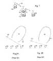
- FIG. 3 ashows four antenna beams B1 304 , B2 306 , B3 308 and B4 310 .
- a vertical axis 300denotes amplitude and a horizontal axis 302 denotes the directional angle of the beam.
- FIG. 3 bshows intermediate beams B1+B2 312 and B3+B4 314 of adjacent beams. These intermediate beams are provided when the same signal is fed to beams forming an intermediate beam. In the case of FIG. 3B , the same signal is fed to the beams B1 304 and B2 306 , and correspondingly to beams B3 308 and B4 310 .
- FIG. 3 cshows an intermediate beam 316 of adjacent beams B2 306 and B3 308 . Also this intermediate beam is provided when the same signal is fed to beams forming an intermediate beam. It can be seen from FIGS. 3 b to 3 c that the intermediate beams are positioned between the generation beams 304 and 306 ; 308 and 310 ; and 306 and 308 , whereby the antenna power can be directed at the desired receiver or transmitter without redirecting the actual antenna beams. By selecting beams and phasing coefficients/amplitude coefficients suitable for generating intermediate beams, the desired power, direction and shape are provided for the intermediate beam.
- FIG. 3 dshows how a beam 318 covering the whole antenna sector is provided by feeding the same signal to all beams 304 , 306 , 308 and 310 . It can be seen from FIG. 3 d that the maximum power of the beam varies wavingly. This variation range of the maximum power can be controlled by the selection of the phasing coefficient.
- the properties of the radio systemsuch as the modulation method selected and also the number of antenna elements in the antenna array, affect the shape of the beams and the waving of the maximum power.
- the pre-phasingis implemented with a phase-shift element, such as with a phase-shift network according to the prior art or with a delay line according to the prior art.
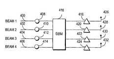
- FIG. 4shows an example of an arrangement for phasing transmission antennas.
- FIG. 4shows implementation of antenna beams by means of a digital system. If the transmission antenna beams to be phased are implemented with an analogue phase-shift network, the power amplifiers are before the analogue beam formation matrix. Signals 400 , 402 , 404 , 406 to each beam are pre-phased with phasing elements 408 , 410 , 412 , 414 , after which the signals are taken to a digital beam formation matrix 416 , which generates antenna beams in accordance with the example of FIGS. 2 a to 2 c .
- the signalsare taken to power amplifiers 418 , 420 , 422 , 424 , by means of which the power of the signals is amplified for the transmission.
- the amplified signalis taken to antenna elements 426 , 428 , 430 , 432 of the antenna array to be transmitted to the radio path.
- FIG. 5shows in more detail the structure of one transceiver 518 .
- An antenna array using directional antenna beamscomprises several separate elements 500 A, 500 B, for example eight different elements, the direction of the antenna beams being performed in the reception. There may be M pieces of antenna elements, whereby M is an integer greater than one.
- the transmissioncan utilize the same antenna elements as the reception, or there may be separate antenna elements 500 C, 500 D for the transmission, as shown in FIG. 5 . Both antenna groups can also be used simultaneously in both the transmission and the reception.
- the antenna elementsare arranged for instance in a linear or planar manner.
- the elementscan be arranged for example as a ULA (Uniform Linear Array), in which the elements are positioned on a straight line at uniform distances from each other.
- a ULAUniform Linear Array
- CAChemical Array
- the elementsare positioned at the same level, for example in the shape of the periphery of a circle in a horizontal manner.
- a given partfor instance 120 degrees or even the whole of the 360 degrees, of the periphery of the circle is covered.
- two- or even three-dimensional structurescan be constructed of the above-mentioned uniplanar antenna structures.
- a two-dimensional structureis formed for instance by positioning ULA structures side by side, whereby a matrix is formed of the elements.
- Each antenna elementhas separate receivers 501 A, 501 B, which are radio frequency parts 530 .
- the receiver 501comprises a filter, which prevents frequencies outside the desired frequency band.
- the receiver 501also comprises a low-noise amplifier. After that, the signal is converted to an intermediate frequency, or directly to a baseband frequency, the signal being sampled and quantified in an analogue/digital converter 502 A, 502 B.
- the multipath-propagated signals expressed in a complex formare then taken to a digital signal processor with its programs 532 .
- the antenna shape of the received signalis directed at digital phasing of the signal, whereby the antenna elements do not have to be mechanically directional.
- the direction of the subscriber terminal 100 , 102is expressed as a complex vector, which is formed of an elementary unit, usually expressed as a complex figure, corresponding to each antenna element.
- Each separate signalis multiplied by the elementary unit of the antenna element in weighting means 542 .
- the weighting means 542are for instance an above-described Butler matrix or, more commonly, an M ⁇ M beam formation matrix, in which M is the number of antenna elements in the antenna array.
- the phasing means 534the signal is pre-phased with a beam-specific phasing coefficient, which comprises a weighting coefficient or a phase or amplitude coefficient. After this, the signals can be combined in combining means 536 .
- the pre-phasing and phasing of a signalcan also be performed for a radio-frequency signal or for an intermediate-frequency signal possibly used.
- the weighting coefficient means 542are positioned in connection with radio-frequency parts 530 or between the radio-frequency parts and the analogue/digital converter 502 A, 502 B.
- a channel equalizer 504compensates interference, such as interference caused by multipath propagation.
- 504 and 536can also be one block, for example a RAKE receiver of the CDMA system.
- a demolutator 506takes a bit stream from the channel-equalized signal, which bit stream is transmitted to a demultiplexer 508 .
- the demultiplexer 508separates the bit stream from different time-slots to separate logic channels.
- a channel codec 516decodes the bit sream of different logic channels, i.e. decides whether the bit stream is signalling information to be transmitted to a control unit 514 or whether the bit stream is speech to be transmitted to the speech codec of the base station controller 106 .
- the channel codec 516also performs error correction.
- the control unit 514performs internal control tasks by controlling different units.
- the radio system usedis a wideband system
- a narrow-band signal on the transmission sideis spread to a wide band one and on the reception side the spread wideband signal is despread into a narrow-band one.
- a multiplexer 526indicates a time-slot for each burst in burst-form transmission.
- a modulator 524modulates the digital signals to a radio-frequency carrier wave.
- the signalis pre-phased with a beam-specific phasing coefficient, which comprises a phase coefficient or a phase and amplitude coefficient.
- a beam-specific phasing coefficientwhich comprises a phase coefficient or a phase and amplitude coefficient.
- the signalis converted from digital into analogue using a digital/analogue converter 522 A, 522 B.
- Each signal componentis transmitted to a transmitter 520 A, 520 B corresponding to each antenna element.
- the transmittercomprises a filter by means of which the bandwidth is reduced. Further, the transmitter controls the output power of the transmission with power amplifiers.
- the synthesizer 512arranges all required frequencies to different units.
- the clock in the synthesizercan be locally controlled, or it can be controlled in a centralized manner from another location, such as from the base station controller 106 .
- the synthesizercreates the required frequencies by means of a voltage-controlled oscillator, for instance.
- pre-phasing meanscan be implemented in a plurality of ways, for instance with software executed by a processor, or with a hardware implementation, such as with a logic constructed of separate components or with the ASIC (Application Specific Integrated Circuit) or with an analogue phasing network.
- ASICApplication Specific Integrated Circuit
- orthogonal beamsare described which are provided by means of a Butler matrix according to the prior art.
- the beamsdo not have to be orthogonal in the pre-phasing method described above.
- the beamscan be directed in a free manner, for example in such a way that the sector can be narrowed. Better isolation between the sectors, for instance, is achieved with narrower sectors, and thus it is also possible to generate the narrower beams in the edges of the sector. In the same way, the side beam level can be reduced.
- the methodcan be widened to a two-dimensional antenna array, whereby the beams can be formed and directed in both the horizontal (azimuth) and elevation direction.
Landscapes
- Variable-Direction Aerials And Aerial Arrays (AREA)
- Radio Transmission System (AREA)
Abstract
Description
where
- λ=wavelength of an antenna signal (carrier wave);
- i=number of antenna elements in the array;
- d=distance between different antenna elements;
- φ=angle at which the antenna beam is directed.
| TABLE 1 | ||||||
| phase | phase | phase | ||||
| Beam | antenna | |||||
| 1 | ||||||
| B1 | 0 | 3πλ/4 | 6πλ/4 | 9πλ/4 | ||
| B2 | 0 | πλ/4 | 2πλ/4 | 3πλ/4 | ||
| B3 | 0 | −πλ/4 | −2πλ/4 | −3πλ/4 | ||
| B4 | 0 | −3πλ/4 | −6πλ/4 | −9πλ/4 | ||
| TABLE 2 | ||
| phase difference Φ (4 | phase difference Φ (8 | |
| Beam | beams) | beams) |
| B1 | 0 | 5πλ/8 |
| B2 | −πλ/4 | 5πλ/8 |
| B3 | 0 | −7πλ/8 |
| B4 | 3πλ/4 | −3πλ/8 |
| B5 | 5πλ/8 | |
| B6 | −3πλ/8 | |
| B7 | −7πλ/8 | |
| B8 | 5πλ/8 | |
Claims (23)
Applications Claiming Priority (3)
| Application Number | Priority Date | Filing Date | Title |
|---|---|---|---|
| FI20002020 | 2000-09-13 | ||
| FI20002020AFI113590B (en) | 2000-09-13 | 2000-09-13 | Method for forming aligned antenna lobes and radio transmitters for the method |
| PCT/FI2001/000794WO2002023670A1 (en) | 2000-09-13 | 2001-09-12 | Method of generating directional antenna beams, and radio transmitter |
Related Parent Applications (1)
| Application Number | Title | Priority Date | Filing Date |
|---|---|---|---|
| PCT/FI2001/000794ContinuationWO2002023670A1 (en) | 2000-09-13 | 2001-09-12 | Method of generating directional antenna beams, and radio transmitter |
Publications (2)
| Publication Number | Publication Date |
|---|---|
| US20030224828A1 US20030224828A1 (en) | 2003-12-04 |
| US7123943B2true US7123943B2 (en) | 2006-10-17 |
Family
ID=8559076
Family Applications (1)
| Application Number | Title | Priority Date | Filing Date |
|---|---|---|---|
| US10/386,942Expired - Fee RelatedUS7123943B2 (en) | 2000-09-13 | 2003-03-13 | Method of generating directional antenna beams, and radio transmitter |
Country Status (6)
| Country | Link |
|---|---|
| US (1) | US7123943B2 (en) |
| EP (1) | EP1338059A1 (en) |
| CN (1) | CN1282389C (en) |
| AU (1) | AU2001287768A1 (en) |
| FI (1) | FI113590B (en) |
| WO (1) | WO2002023670A1 (en) |
Cited By (3)
| Publication number | Priority date | Publication date | Assignee | Title |
|---|---|---|---|---|
| US20050266799A1 (en)* | 2004-05-26 | 2005-12-01 | Fujitsu Ltd | Radio base station apparatus and radio communication method |
| US20110191090A1 (en)* | 2008-10-06 | 2011-08-04 | Elektrobit System Test Oy | Over-the-air test |
| US20120326928A1 (en)* | 2010-02-25 | 2012-12-27 | Telefonaktiebolaget L M Ericsson (Publ) | Communication system node comprising a transformation matrix |
Families Citing this family (9)
| Publication number | Priority date | Publication date | Assignee | Title |
|---|---|---|---|---|
| FI5706U1 (en) | 2002-11-21 | 2003-02-26 | Patria New Technologies Oy | JTAG test apparatus and testing system |
| US8073490B2 (en)* | 2003-12-19 | 2011-12-06 | Samsung Electronics Co., Ltd. | Mobile station direction finding based on observation of forward link |
| US7088289B1 (en)* | 2005-04-05 | 2006-08-08 | Nokia Corporation | Antenna adaptation method, communication terminal, device; module and computer program product |
| CN101336524B (en)* | 2006-02-02 | 2013-07-24 | 富士通株式会社 | Wireless transmission method, wireless transmitter and wireless receiver |
| US8675617B2 (en)* | 2006-06-02 | 2014-03-18 | Interdigital Technology Corporation | Methods for improving wireless communications when interference or signal loss is directional in nature |
| CN105515628B (en)* | 2015-12-22 | 2019-02-26 | 石家庄开发区泰顺电子通讯有限公司 | Using the short-wave band communication system and short wave communication method of active phased array principle |
| US20180294567A1 (en)* | 2017-04-06 | 2018-10-11 | The Charles Stark Draper Laboratory, Inc. | Patch antenna system with parasitic edge-aligned elements |
| US10505616B1 (en) | 2018-06-01 | 2019-12-10 | Samsung Electronics Co., Ltd. | Method and apparatus for machine learning based wide beam optimization in cellular network |
| CN119213727A (en)* | 2022-08-18 | 2024-12-27 | 华为技术有限公司 | An antenna system |
Citations (17)
| Publication number | Priority date | Publication date | Assignee | Title |
|---|---|---|---|---|
| US4032922A (en)* | 1976-01-09 | 1977-06-28 | The United States Of America As Represented By The Secretary Of The Navy | Multibeam adaptive array |
| US4410894A (en) | 1981-02-17 | 1983-10-18 | Bell Telephone Laboratories, Incorporated | Array phasing techniques for wide area coverage in a failure mode |
| US4638317A (en) | 1984-06-19 | 1987-01-20 | Westinghouse Electric Corp. | Orthogonal beam forming network |
| US5414433A (en)* | 1994-02-16 | 1995-05-09 | Raytheon Company | Phased array radar antenna with two-stage time delay units |
| US5649287A (en)* | 1995-03-29 | 1997-07-15 | Telefonaktiebolaget Lm Ericsson | Orthogonalizing methods for antenna pattern nullfilling |
| WO1998036471A1 (en) | 1997-02-13 | 1998-08-20 | Nokia Telecommunications Oy | Method and apparatus for directional radio communication |
| US5831977A (en)* | 1996-09-04 | 1998-11-03 | Ericsson Inc. | Subtractive CDMA system with simultaneous subtraction in code space and direction-of-arrival space |
| WO1998050981A1 (en) | 1997-05-07 | 1998-11-12 | Telefonaktiebolaget Lm Ericsson (Publ) | Radio antenna system |
| US5859610A (en)* | 1994-06-16 | 1999-01-12 | Alcatel N.V. | Method and a system for locating ground equipment transmitting via satellites |
| US5952968A (en)* | 1997-09-15 | 1999-09-14 | Rockwell International Corporation | Method and apparatus for reducing jamming by beam forming using navigational data |
| US5963165A (en)* | 1996-05-22 | 1999-10-05 | Manoj Bhatta Charyya | Transmit-receive telecommunication system with high efficiency multibeam equally loaded transmitters |
| US6009335A (en)* | 1997-09-26 | 1999-12-28 | Rockwell Science Center, Inc. | Method of calibrating and testing spatial nulling antenna |
| US6151513A (en)* | 1995-09-23 | 2000-11-21 | Robert Bosch Gmbh | Aerial for a central station of a point-to-multi-point radio link system |
| US20020196185A1 (en)* | 2000-11-01 | 2002-12-26 | Bloy Graham P. | Active high density multi-element directional antenna system |
| US6546259B1 (en)* | 2000-06-20 | 2003-04-08 | Lockheed Martin Corporation | Method and system for autonomous two-way radio frequency communication |
| US20030076258A1 (en)* | 2000-09-05 | 2003-04-24 | Hughes Electronics Corporation | Wavefront-projection beamformer |
| US6580701B1 (en)* | 1997-07-04 | 2003-06-17 | Nokia Corporation | Interpretation of a received signal |
Family Cites Families (2)
| Publication number | Priority date | Publication date | Assignee | Title |
|---|---|---|---|---|
| FR2672436B1 (en) | 1991-01-31 | 1993-09-10 | Europ Agence Spatiale | DEVICE FOR ELECTRONICALLY MONITORING THE RADIATION DIAGRAM OF AN ANTENNA WITH ONE OR MORE VARIABLE STEERING AND / OR WIDTH BEAMS. |
| FR2750258B1 (en) | 1996-06-24 | 1998-08-21 | Europ Agence Spatiale | RECONFIGURABLE ZONAL BEAM CONFORMATION SYSTEM FOR AN EMBEDDED ANTENNA ON AN ORBIT SATELLITE AND METHOD FOR OPTIMIZING RECONFIGURATION |
- 2000
- 2000-09-13FIFI20002020Apatent/FI113590B/ennot_activeIP Right Cessation
- 2001
- 2001-09-12EPEP01967380Apatent/EP1338059A1/ennot_activeWithdrawn
- 2001-09-12WOPCT/FI2001/000794patent/WO2002023670A1/enactiveApplication Filing
- 2001-09-12CNCNB018155812Apatent/CN1282389C/ennot_activeExpired - Fee Related
- 2001-09-12AUAU2001287768Apatent/AU2001287768A1/ennot_activeAbandoned
- 2003
- 2003-03-13USUS10/386,942patent/US7123943B2/ennot_activeExpired - Fee Related
Patent Citations (17)
| Publication number | Priority date | Publication date | Assignee | Title |
|---|---|---|---|---|
| US4032922A (en)* | 1976-01-09 | 1977-06-28 | The United States Of America As Represented By The Secretary Of The Navy | Multibeam adaptive array |
| US4410894A (en) | 1981-02-17 | 1983-10-18 | Bell Telephone Laboratories, Incorporated | Array phasing techniques for wide area coverage in a failure mode |
| US4638317A (en) | 1984-06-19 | 1987-01-20 | Westinghouse Electric Corp. | Orthogonal beam forming network |
| US5414433A (en)* | 1994-02-16 | 1995-05-09 | Raytheon Company | Phased array radar antenna with two-stage time delay units |
| US5859610A (en)* | 1994-06-16 | 1999-01-12 | Alcatel N.V. | Method and a system for locating ground equipment transmitting via satellites |
| US5649287A (en)* | 1995-03-29 | 1997-07-15 | Telefonaktiebolaget Lm Ericsson | Orthogonalizing methods for antenna pattern nullfilling |
| US6151513A (en)* | 1995-09-23 | 2000-11-21 | Robert Bosch Gmbh | Aerial for a central station of a point-to-multi-point radio link system |
| US5963165A (en)* | 1996-05-22 | 1999-10-05 | Manoj Bhatta Charyya | Transmit-receive telecommunication system with high efficiency multibeam equally loaded transmitters |
| US5831977A (en)* | 1996-09-04 | 1998-11-03 | Ericsson Inc. | Subtractive CDMA system with simultaneous subtraction in code space and direction-of-arrival space |
| WO1998036471A1 (en) | 1997-02-13 | 1998-08-20 | Nokia Telecommunications Oy | Method and apparatus for directional radio communication |
| WO1998050981A1 (en) | 1997-05-07 | 1998-11-12 | Telefonaktiebolaget Lm Ericsson (Publ) | Radio antenna system |
| US6580701B1 (en)* | 1997-07-04 | 2003-06-17 | Nokia Corporation | Interpretation of a received signal |
| US5952968A (en)* | 1997-09-15 | 1999-09-14 | Rockwell International Corporation | Method and apparatus for reducing jamming by beam forming using navigational data |
| US6009335A (en)* | 1997-09-26 | 1999-12-28 | Rockwell Science Center, Inc. | Method of calibrating and testing spatial nulling antenna |
| US6546259B1 (en)* | 2000-06-20 | 2003-04-08 | Lockheed Martin Corporation | Method and system for autonomous two-way radio frequency communication |
| US20030076258A1 (en)* | 2000-09-05 | 2003-04-24 | Hughes Electronics Corporation | Wavefront-projection beamformer |
| US20020196185A1 (en)* | 2000-11-01 | 2002-12-26 | Bloy Graham P. | Active high density multi-element directional antenna system |
Cited By (7)
| Publication number | Priority date | Publication date | Assignee | Title |
|---|---|---|---|---|
| US20050266799A1 (en)* | 2004-05-26 | 2005-12-01 | Fujitsu Ltd | Radio base station apparatus and radio communication method |
| US7801563B2 (en)* | 2004-05-26 | 2010-09-21 | Fujitsu Limited | Radio base station apparatus and radio communication method |
| US20110191090A1 (en)* | 2008-10-06 | 2011-08-04 | Elektrobit System Test Oy | Over-the-air test |
| US9786999B2 (en) | 2008-10-06 | 2017-10-10 | Keysight Technologies Singapore (Holdings) Pte. Ltd. | Over-the-air test |
| US11152717B2 (en)* | 2008-10-06 | 2021-10-19 | Keysight Technologies Singapore (Sales) Pte. Ltd. | Over-the-air test |
| US20120326928A1 (en)* | 2010-02-25 | 2012-12-27 | Telefonaktiebolaget L M Ericsson (Publ) | Communication system node comprising a transformation matrix |
| US9728850B2 (en)* | 2010-02-25 | 2017-08-08 | Telefonaktiebolaget Lm Ericsson (Publ) | Communication system node comprising a transformation matrix |
Also Published As
| Publication number | Publication date |
|---|---|
| WO2002023670A1 (en) | 2002-03-21 |
| FI20002020L (en) | 2002-03-14 |
| FI113590B (en) | 2004-05-14 |
| CN1282389C (en) | 2006-10-25 |
| AU2001287768A1 (en) | 2002-03-26 |
| EP1338059A1 (en) | 2003-08-27 |
| US20030224828A1 (en) | 2003-12-04 |
| FI20002020A0 (en) | 2000-09-13 |
| CN1455972A (en) | 2003-11-12 |
Similar Documents
| Publication | Publication Date | Title |
|---|---|---|
| US7203519B2 (en) | Implementation method of pilot signal | |
| US7312750B2 (en) | Adaptive beam-forming system using hierarchical weight banks for antenna array in wireless communication system | |
| US7113748B2 (en) | System and method for improving polarization matching on a cellular communication forward link | |
| US7373177B2 (en) | Data transmission method and arrangement | |
| US9160427B1 (en) | Transmit diversity with formed beams in a wireless communications system using a common pilot channel | |
| JP5432879B2 (en) | Method and apparatus for a multi-beam antenna system | |
| KR100817620B1 (en) | Method and apparatus for adapting antenna array using received predetermined signal | |
| US7203246B2 (en) | Method of estimating a channel, and a radio system | |
| EP0840961B1 (en) | Self-calibration apparatus and method for communication device | |
| US6463301B1 (en) | Base stations for use in cellular communications systems | |
| US7342912B1 (en) | Selection of user-specific transmission parameters for optimization of transmit performance in wireless communications using a common pilot channel | |
| WO1994009568A1 (en) | Adaptive co-channel interference reduction system for cellular telephone central base stations | |
| US7123943B2 (en) | Method of generating directional antenna beams, and radio transmitter | |
| EP1178562A1 (en) | Antenna array calibration | |
| US6865377B1 (en) | Combined open and closed loop beam forming in a multiple array radio communication system | |
| US7069052B2 (en) | Data transmission method in base station of radio system, base station of radio system, and antenna array of base station | |
| US20040048580A1 (en) | Base transceiver station | |
| Kühne et al. | Performance simulation of a 5G hybrid beamforming millimeter-wave system | |
| KR100383008B1 (en) | Base station system, and wireless communication method | |
| Gautam et al. | Beamforming investigation for wireless communication at 60 GHz | |
| JP3451231B2 (en) | Adaptive zone formation system | |
| JP2003338772A (en) | CDMA mobile communication base station device | |
| HK1100794B (en) | Method and apparatus for multi-beam antenna system |
Legal Events
| Date | Code | Title | Description |
|---|---|---|---|
| AS | Assignment | Owner name:NOKIA CORPORATION, FINLAND Free format text:ASSIGNMENT OF ASSIGNORS INTEREST;ASSIGNOR:YLITALO, JUHA;REEL/FRAME:014256/0939 Effective date:20030617 | |
| AS | Assignment | Owner name:NOKIA SIEMENS NETWORKS OY, FINLAND Free format text:ASSIGNMENT OF ASSIGNORS INTEREST;ASSIGNOR:NOKIA CORPORATION;REEL/FRAME:020550/0001 Effective date:20070913 Owner name:NOKIA SIEMENS NETWORKS OY,FINLAND Free format text:ASSIGNMENT OF ASSIGNORS INTEREST;ASSIGNOR:NOKIA CORPORATION;REEL/FRAME:020550/0001 Effective date:20070913 | |
| FPAY | Fee payment | Year of fee payment:4 | |
| FPAY | Fee payment | Year of fee payment:8 | |
| AS | Assignment | Owner name:NOKIA SOLUTIONS AND NETWORKS OY, FINLAND Free format text:CHANGE OF NAME;ASSIGNOR:NOKIA SIEMENS NETWORKS OY;REEL/FRAME:034294/0603 Effective date:20130819 | |
| AS | Assignment | Owner name:PROVENANCE ASSET GROUP LLC, CONNECTICUT Free format text:ASSIGNMENT OF ASSIGNORS INTEREST;ASSIGNORS:NOKIA TECHNOLOGIES OY;NOKIA SOLUTIONS AND NETWORKS BV;ALCATEL LUCENT SAS;REEL/FRAME:043877/0001 Effective date:20170912 Owner name:NOKIA USA INC., CALIFORNIA Free format text:SECURITY INTEREST;ASSIGNORS:PROVENANCE ASSET GROUP HOLDINGS, LLC;PROVENANCE ASSET GROUP LLC;REEL/FRAME:043879/0001 Effective date:20170913 Owner name:CORTLAND CAPITAL MARKET SERVICES, LLC, ILLINOIS Free format text:SECURITY INTEREST;ASSIGNORS:PROVENANCE ASSET GROUP HOLDINGS, LLC;PROVENANCE ASSET GROUP, LLC;REEL/FRAME:043967/0001 Effective date:20170913 | |
| FEPP | Fee payment procedure | Free format text:MAINTENANCE FEE REMINDER MAILED (ORIGINAL EVENT CODE: REM.) | |
| LAPS | Lapse for failure to pay maintenance fees | Free format text:PATENT EXPIRED FOR FAILURE TO PAY MAINTENANCE FEES (ORIGINAL EVENT CODE: EXP.); ENTITY STATUS OF PATENT OWNER: LARGE ENTITY | |
| STCH | Information on status: patent discontinuation | Free format text:PATENT EXPIRED DUE TO NONPAYMENT OF MAINTENANCE FEES UNDER 37 CFR 1.362 | |
| FP | Lapsed due to failure to pay maintenance fee | Effective date:20181017 | |
| AS | Assignment | Owner name:NOKIA US HOLDINGS INC., NEW JERSEY Free format text:ASSIGNMENT AND ASSUMPTION AGREEMENT;ASSIGNOR:NOKIA USA INC.;REEL/FRAME:048370/0682 Effective date:20181220 | |
| AS | Assignment | Owner name:PROVENANCE ASSET GROUP LLC, CONNECTICUT Free format text:RELEASE BY SECURED PARTY;ASSIGNOR:CORTLAND CAPITAL MARKETS SERVICES LLC;REEL/FRAME:058983/0104 Effective date:20211101 Owner name:PROVENANCE ASSET GROUP HOLDINGS LLC, CONNECTICUT Free format text:RELEASE BY SECURED PARTY;ASSIGNOR:CORTLAND CAPITAL MARKETS SERVICES LLC;REEL/FRAME:058983/0104 Effective date:20211101 Owner name:PROVENANCE ASSET GROUP LLC, CONNECTICUT Free format text:RELEASE BY SECURED PARTY;ASSIGNOR:NOKIA US HOLDINGS INC.;REEL/FRAME:058363/0723 Effective date:20211129 Owner name:PROVENANCE ASSET GROUP HOLDINGS LLC, CONNECTICUT Free format text:RELEASE BY SECURED PARTY;ASSIGNOR:NOKIA US HOLDINGS INC.;REEL/FRAME:058363/0723 Effective date:20211129 | |
| AS | Assignment | Owner name:RPX CORPORATION, CALIFORNIA Free format text:ASSIGNMENT OF ASSIGNORS INTEREST;ASSIGNOR:PROVENANCE ASSET GROUP LLC;REEL/FRAME:059352/0001 Effective date:20211129 |