US7123886B2 - Handheld mobile phone with a detachable battery pack - Google Patents
Handheld mobile phone with a detachable battery packDownload PDFInfo
- Publication number
- US7123886B2 US7123886B2US10/132,272US13227202AUS7123886B2US 7123886 B2US7123886 B2US 7123886B2US 13227202 AUS13227202 AUS 13227202AUS 7123886 B2US7123886 B2US 7123886B2
- Authority
- US
- United States
- Prior art keywords
- memory card
- mobile phone
- battery pack
- handheld mobile
- detachable battery
- Prior art date
- Legal status (The legal status is an assumption and is not a legal conclusion. Google has not performed a legal analysis and makes no representation as to the accuracy of the status listed.)
- Expired - Fee Related, expires
Links
- 230000009471actionEffects0.000description3
- 230000007246mechanismEffects0.000description3
- 230000000717retained effectEffects0.000description3
- 230000000916dilatatory effectEffects0.000description1
- 230000006870functionEffects0.000description1
- 230000004048modificationEffects0.000description1
- 238000012986modificationMethods0.000description1
Images


Classifications
- H—ELECTRICITY
- H04—ELECTRIC COMMUNICATION TECHNIQUE
- H04B—TRANSMISSION
- H04B1/00—Details of transmission systems, not covered by a single one of groups H04B3/00 - H04B13/00; Details of transmission systems not characterised by the medium used for transmission
- H04B1/38—Transceivers, i.e. devices in which transmitter and receiver form a structural unit and in which at least one part is used for functions of transmitting and receiving
- H04B1/3816—Mechanical arrangements for accommodating identification devices, e.g. cards or chips; with connectors for programming identification devices
- H—ELECTRICITY
- H04—ELECTRIC COMMUNICATION TECHNIQUE
- H04B—TRANSMISSION
- H04B1/00—Details of transmission systems, not covered by a single one of groups H04B3/00 - H04B13/00; Details of transmission systems not characterised by the medium used for transmission
- H04B1/38—Transceivers, i.e. devices in which transmitter and receiver form a structural unit and in which at least one part is used for functions of transmitting and receiving
- H04B1/3827—Portable transceivers
- H04B1/3883—Arrangements for mounting batteries or battery chargers
- H—ELECTRICITY
- H04—ELECTRIC COMMUNICATION TECHNIQUE
- H04M—TELEPHONIC COMMUNICATION
- H04M1/00—Substation equipment, e.g. for use by subscribers
- H04M1/02—Constructional features of telephone sets
- H04M1/0202—Portable telephone sets, e.g. cordless phones, mobile phones or bar type handsets
- H04M1/026—Details of the structure or mounting of specific components
- H04M1/0262—Details of the structure or mounting of specific components for a battery compartment
- Y—GENERAL TAGGING OF NEW TECHNOLOGICAL DEVELOPMENTS; GENERAL TAGGING OF CROSS-SECTIONAL TECHNOLOGIES SPANNING OVER SEVERAL SECTIONS OF THE IPC; TECHNICAL SUBJECTS COVERED BY FORMER USPC CROSS-REFERENCE ART COLLECTIONS [XRACs] AND DIGESTS
- Y02—TECHNOLOGIES OR APPLICATIONS FOR MITIGATION OR ADAPTATION AGAINST CLIMATE CHANGE
- Y02E—REDUCTION OF GREENHOUSE GAS [GHG] EMISSIONS, RELATED TO ENERGY GENERATION, TRANSMISSION OR DISTRIBUTION
- Y02E60/00—Enabling technologies; Technologies with a potential or indirect contribution to GHG emissions mitigation
- Y02E60/10—Energy storage using batteries
Definitions
- the present inventionrelates to a handheld mobile phone capable of utilizing an exchangeable memory card, and more specifically to a handheld mobile phone capable of utilizing an exchangeable memory card, which can be mounted on a detachable battery pack.
- Some of prior art handheld mobile phoneshave a memory card detachable to a body of the handheld mobile phone and the function of recording a conversation in the memory card and reproducing the conversation recorded in the memory card, so that it is possible to save a dilatory handwork for memorizing the summary of the conversation or for pressing a key pad for calling (For example, JP-A-2000-032169).
- the connectoris required to have a housing for pushing terminals of the memory card to the connector, with the result that it is difficult to thin the body of the handheld mobile phone.
- Another object of the present inventionis to provide a handheld mobile phone having a memory card, capable of efficiently utilizing the space on the printed circuit board.
- Still another object of the present inventionis to provide a handheld mobile phone having a memory card, capable of efficiently thinning the body of the handheld mobile phone.
- a handheld mobile phonehaving a detachable battery pack which can be removably mounted to a body of the handheld mobile phone, wherein the detachable battery pack has a memory card receiving part for removably receiving a body of a memory card, and the body of the handheld mobile phone has a plurality of external contacts which are brought into electrical contact with contact terminals of the memory card mounted to the detachable battery pack when the detachable battery pack is mounted to the body of the handheld mobile phone.
- the memory card receiving part of the detachable battery packis so configured to receive the memory card in such a condition that the contact terminals of the memory card are exposed to the body of the handheld mobile phone, and the plurality of external contacts provided in the body of the handheld mobile phone are formed of a plurality of springy contacts which are brought into resilient contact with the contact terminals of the memory card mounted to the detachable battery pack when the detachable battery pack is mounted to the body of the handheld mobile phone.
- the detachable battery packincludes a receiving port through which the memory card is inserted from an external, a guide means for guiding the memory card from the receiving port to the memory card receiving part, and a retaining means for detachably latching the memory card accommodated in the memory card receiving part.
- the receiving portis exposed when the detachable battery pack is mounted to the body of the handheld mobile phone.
- the detachable battery packincludes a spring provided at a deep end of the memory card receiving part, for exerting on the memory card a biasing force pushing the memory card toward the receiving port
- the memory card receiving parthas a stopper for preventing the memory card from being inserted to the memory card receiving part when the memory card is improperly inserted from the receiving port, and the memory card has a cut which is never contacted with the stopper when the memory card is properly inserted from the receiving port to the memory card receiving part.
- the detachable battery packhas the memory card receiving part removably receiving the body of the memory card
- the body of the handheld mobile phonehas the external contacts which are brought into contact with the contact terminals of the memory card mounted to the battery pack when the battery pack is fitted into the body of the handheld mobile phone.
- the external contactsare connected to an electronic circuit internally provided within the body of the handheld mobile phone.
- the body of the handheld mobile phonecan be effectively thinned and a space on the printed circuit board can be efficiently utilized.
- FIG. 1is a diagrammatic perspective view of an embodiment of the handheld mobile phone in accordance with the present invention in a condition that a battery pack is fitted into the body of a foldable handheld mobile phone in a folded condition;
- FIG. 2is a diagrammatic perspective view of the handheld mobile phone shown in FIG. 1 in a condition that the battery pack was removed from the body of the foldable handheld mobile phone in the folded condition;
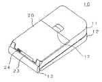
- FIG. 3is a diagrammatic perspective view of the battery pack which was detached from the body of the foldable handheld mobile phone shown in FIG. 1 and from which the memory card was removed;
- FIG. 4is a diagrammatic perspective view of the memory card, which can be fitted into the battery pack shown in FIG. 3 .
- the shown embodiment of the handheld mobile phone in accordance with the present inventionis a foldable handheld mobile phone (two-part folding mobile phone) 10 , which is shown in a folded condition in FIGS. 1 and 2 .
- FIG. 1in a condition that a battery pack is fitted into the body of a foldable handheld mobile phone in folded condition
- FIG. 2shows a condition that the battery pack was removed from the body of the foldable handheld mobile phone in the folded condition.
- the shown foldable handheld mobile phone 10comprises an operating part housing 11 and a display part housing 12 which are rotatably or swingably coupled together by means of a hinge mechanism 13 .
- the operating part housing 11includes a key pad (not shown) and a microphone (not shown) on an inner and front face (not shown) thereof
- the display part housing 12includes an ear speaker (not shown) and a display (not shown) on an inner and front face (not shown) thereof.
- an outer and rear face of the operating part housing 11has a battery pack receiving recess 14 extending from a central portion to a side adjacent to the hinge mechanism 13 and having a wide cut 14 A formed in a recess wall 14 B adjacent to the hinge mechanism 13 so that a battery pack 20 is detachably fitted into the receiving recess 14 in such a manner that a base end of the battery pack 20 is exposed at the wide cut 14 A.
- a spring-biased latch 17is provided at the central portion side of the battery pack receiving recess 14 to latch the battery pack 20 detachably fitted into the receiving recess 14 , for holding the battery pack 20 in an unremovable condition.
- an array of external springy contacts 15are formed and projected to electrically and resiliently contact with contact terminals 31 of a memory card 30 shown in FIG. 4 .
- the array of external springy contacts 15are electrically connected to an internal electronic circuit (not shown) provided within the body of the mobile phone 10 .
- power terminals 16are provided on the bottom surface of the battery pack receiving recess 14 to contact with power supplying terminals 21 of the battery pack 20 so as to receive an electric power from the battery pack 20 when the battery pack 20 is fitted into the battery pack receiving recess 14 of the operating part housing 11 .
- the power terminals 16are electrically connected to power supply terminals of the internal electronic circuit (not shown) provided within the body of the mobile phone 10 .
- the battery pack 20includes therein a secondary cell or cells (not shown) in a casing, which includes a pair of contact terminals 21 provided on a mounting surface thereof to be brought into contact with the power terminals 16 of the operating part housing 11 when the battery pack 20 is fitted into the battery pack receiving recess 14 of the operating part housing 11 .
- the mounting surface of the casing of the battery pack 20includes a memory card receiving recess 22 to slidably receive the memory card 30 from a receiving port 23 portioned at a side of the wide cut 14 A formed in the recess wall 14 B of the operating part housing 11 in the condition that the battery pack 20 is fitted into the battery pack receiving recess 14 of the operating part housing 11 .
- the battery pack 20also includes a pair of guiding grooves 26 formed at opposite sides of the memory card receiving recess 22 , so that the memory card 30 can be slidingly guided in the pair of guiding grooves 26 when the memory card 30 is inserted into or ejected from the memory card receiving recess 22 .
- the battery pack 20further includes a spring 25 provided at a deepest end of the memory card receiving recess 22 opposite to the receiving port 23 , for exerting a springy biasing force on the memory card 30 in a direction ejecting the memory card 30 toward the receiving port 23 when the memory card 30 is completely inserted in the memory card receiving recess 22 .
- the battery pack 20includes an inclined stopper surface 27 formed on one corner of the deepest end of the memory card receiving recess 22 so that when the memory card 30 having an cut 32 formed at one corner of a tip end side thereof is properly inserted into the memory card receiving recess 22 along the pair of guiding grooves 26 , the cut corner 32 of the memory card 30 is faced to the inclined stopper surface 27 with no contact with the inclined stopper surface 27 , and therefore, the memory card 30 can be inserted in the deepest position contacting and pushing the spring 25 , and on the other hand, when the memory card 30 is improperly inserted into the memory card receiving recess 22 , a non-cut corner 33 of the tip end side of the memory card 30 is abutted against the inclined stopper surface 27 with the result that the memory card 30 cannot be inserted until the deepest position.
- a memory card retaining slider 24is provided to be slidable along the mouth of the receiving port 23 between a latching position for latching the memory card 30 properly inserted into the memory card receiving recess 22 and therefore for preventing the memory card 30 from being ejected from the memory card receiving recess 22 by the ejecting biasing force of the spring 25 , and an ejecting position as shown in FIG. 3 for releasing the memory card 30 properly inserted into the memory card receiving recess 22 so that the memory card 30 is partially ejected from the memory card receiving recess 22 by action of the ejecting biasing force of the spring 25 .
- This memory card retaining slider 24can be spring-biased to be automatically slid to the latching position when the memory card 30 has been properly and completely inserted into the memory card receiving recess 22 .
- the memory card 30is an external memory, such as a multi-media card, a SD memory card, and a memory stick, removable to the battery pack 20 .
- the memory card 30includes an array of contact terminals 31 formed along the tip end side thereof to be brought into an electrical contact with the springy contacts 15 of the operating part housing 11 when the memory card 30 is properly and completely inserted and fitted into the memory card receiving recess 22 of the battery pack 20 fitted into the battery pack receiving recess 14 of the operating part housing 11 .
- the memory card 30has the cut 32 formed at the one corner of the tip end side thereof, so that the memory card 30 can be completely inserted into the deepest position when the memory card 30 is properly inserted into the memory card receiving recess 22 along the pair of guiding grooves 26 in such a manner that the cut corner 32 of the memory card 30 is faced to the inclined stopper surface 27 .
- the memory card 30In order to insert the memory card 30 into the handheld mobile phone 10 , the memory card 30 is inserted from the memory card receiving port 23 of the battery pack 20 in a condition that the contact terminals 31 is faced outward, and is slid along the pair of guiding grooves 26 .
- the slider 24When the memory card 30 is properly completely inserted into the memory card receiving recess 22 against the spring 25 , the slider 24 is slid from the ejecting position as shown in FIG. 3 to the latching position (slightly displaced from the ejecting position as shown in FIG.
- the memory card 30is retained in the battery pack 20 in an unremovable condition.
- the battery pack 20 having the memory card 30 retained thereinis fitted into the the battery pack receiving recess 14 of the foldable handheld mobile phone 10 in the folded condition, and held in the unremovable condition by the spring-biased latch 17 .
- the power supplying terminals 21 of the battery pack 20are brought into electrical contact with the power terminals 16 of the handheld mobile phone 10
- the contact terminals 31 of a memory card 30are simultaneously brought into electrical and resilient contact with the springy contacts 15 of the handheld mobile phone 10 .
- the memory card 30can be inserted and removed from the battery pack 20 fitted with the handheld mobile phone 10 .
- the memory card 30is released from the slider 24 and partially ejected from the memory card receiving port 23 by action of the spring 25 .
- the handheld mobile phoneis of the foldable type, but the present invention can be equally applied to a not-foldable handheld mobile phone if it is uses a detachable battery pack.
- the connector mounted on the printed circuit board provided in the body of the handheld mobile phoneis the springy contacts without any guide for fitting the memory card within the body of the handheld mobile phone, a space on the printed circuit board can be efficiently utilized, and the size of the body of the handheld mobile phone can be reduced.
Landscapes
- Engineering & Computer Science (AREA)
- Signal Processing (AREA)
- Computer Networks & Wireless Communication (AREA)
- Telephone Set Structure (AREA)
- Power Sources (AREA)
- Charge And Discharge Circuits For Batteries Or The Like (AREA)
- Battery Mounting, Suspending (AREA)
- Mobile Radio Communication Systems (AREA)
Abstract
Description
Claims (8)
Applications Claiming Priority (2)
| Application Number | Priority Date | Filing Date | Title |
|---|---|---|---|
| JP2001130681AJP4306143B2 (en) | 2001-04-27 | 2001-04-27 | Mobile phone |
| JP2001-130681 | 2001-04-27 |
Publications (2)
| Publication Number | Publication Date |
|---|---|
| US20020160728A1 US20020160728A1 (en) | 2002-10-31 |
| US7123886B2true US7123886B2 (en) | 2006-10-17 |
Family
ID=18979005
Family Applications (1)
| Application Number | Title | Priority Date | Filing Date |
|---|---|---|---|
| US10/132,272Expired - Fee RelatedUS7123886B2 (en) | 2001-04-27 | 2002-04-26 | Handheld mobile phone with a detachable battery pack |
Country Status (4)
| Country | Link |
|---|---|
| US (1) | US7123886B2 (en) |
| JP (1) | JP4306143B2 (en) |
| CN (1) | CN1213584C (en) |
| GB (1) | GB2379068B (en) |
Cited By (6)
| Publication number | Priority date | Publication date | Assignee | Title |
|---|---|---|---|---|
| USD539277S1 (en)* | 2005-02-04 | 2007-03-27 | Matsushita Electric Industrial Co., Ltd. | Panel for a mobile phone |
| US20070128913A1 (en)* | 2005-12-02 | 2007-06-07 | Shenzhen Futaihong Precision Industrial Co,.Ltd. | Surface contact card holder |
| US20090143112A1 (en)* | 2007-11-30 | 2009-06-04 | Compal Communications, Inc. | Battery and mobile communication apparatus including the same |
| US20090221184A1 (en)* | 2006-03-02 | 2009-09-03 | Molex Incorporated | Card Connector |
| US20090233655A1 (en)* | 2008-03-14 | 2009-09-17 | Shenzhen Futaihong Precision Industry Co., Ltd. | Portable electronic device |
| US20150326267A1 (en)* | 2012-12-18 | 2015-11-12 | Kyocera Corporation | Wireless communication terminal device |
Families Citing this family (15)
| Publication number | Priority date | Publication date | Assignee | Title |
|---|---|---|---|---|
| US20030217210A1 (en)* | 2002-05-15 | 2003-11-20 | Carau Frank P. | Memory card having an integral battery that powers an electronic device |
| CN100385710C (en)* | 2002-10-11 | 2008-04-30 | 松下电器产业株式会社 | portable electronic device |
| US20050036801A1 (en)* | 2003-08-15 | 2005-02-17 | Static Control Components | Casing for an electronic circuit |
| US20050050248A1 (en)* | 2003-08-29 | 2005-03-03 | Dennis York | Portable electronic instrument with field-replaceable battery/input/output module |
| US6875041B1 (en)* | 2003-09-15 | 2005-04-05 | Benq Corporation | Latch for electrical device combined with data card ejector |
| TWM261948U (en)* | 2004-08-17 | 2005-04-11 | Singim Internat Corp | Bluetooth communication earphone with detachable battery module |
| GB2423616A (en)* | 2005-02-28 | 2006-08-30 | Nec Technologies | Card device mounted on a mobile phone battery |
| KR100664210B1 (en)* | 2005-09-01 | 2007-01-03 | 엘지전자 주식회사 | Battery separator of mobile communication terminal |
| KR20110060144A (en)* | 2009-11-30 | 2011-06-08 | 삼성전자주식회사 | Collapsible handheld device |
| WO2011073916A1 (en) | 2009-12-16 | 2011-06-23 | Steve Wheeler | Disposable shield for a medical tool |
| FR2957202B1 (en)* | 2010-03-05 | 2012-03-30 | Sagem Defense Securite | BATTERY AND ASSEMBLY ELECTRICAL EQUIPMENT AND BATTERY FOR POWERING THE EQUIPMENT |
| HK1154177A2 (en)* | 2011-09-30 | 2012-04-13 | 萨爽 | Battery device for uninterrupted power supply and electronic device with such a battery device |
| CN104081574B (en)* | 2011-12-20 | 2017-06-30 | 诺基亚技术有限公司 | Devices and portable electronic devices for storing electrical energy |
| JP6111555B2 (en)* | 2012-07-06 | 2017-04-12 | セイコーエプソン株式会社 | Container mounting mechanism and recording apparatus |
| DE102014217347A1 (en)* | 2014-08-29 | 2016-03-03 | Sennheiser Electronic Gmbh & Co. Kg | Wireless pocket transmitter, accumulator unit for a wireless bodypack transmitter, wireless microphone, accumulator for a wireless microphone and charging unit for a bodypack transmitter and / or a microphone |
Citations (18)
| Publication number | Priority date | Publication date | Assignee | Title |
|---|---|---|---|---|
| EP0505931A2 (en) | 1991-03-28 | 1992-09-30 | HAGENUK GmbH | Telephone, particularly wireless-telephone |
| EP0635963A2 (en) | 1993-07-23 | 1995-01-25 | Nec Corporation | Portable telephone set for use with IC card |
| US5768370A (en)* | 1997-01-08 | 1998-06-16 | Nokia Mobile Phones, Ltd. | User changeable cosmetic phone interface |
| US5797089A (en)* | 1995-09-07 | 1998-08-18 | Telefonaktiebolaget Lm Ericsson (Publ) | Personal communications terminal having switches which independently energize a mobile telephone and a personal digital assistant |
| US5896574A (en)* | 1996-10-09 | 1999-04-20 | International Business Machines Corporation | Wireless modem with a supplemental power source |
| US5918189A (en)* | 1996-09-30 | 1999-06-29 | Nokia Mobile Phones, Ltd. | Exchangeable hardware module for radiotelephone |
| EP0967771A2 (en) | 1998-06-27 | 1999-12-29 | Samsung Electronics Co., Ltd. | Sim card terminal |
| GB2347568A (en) | 1997-12-29 | 2000-09-06 | Intel Corp | High speed ratioed CMOS logic structures for a pulsed input |
| CN1265548A (en) | 1999-03-02 | 2000-09-06 | 日本电气株式会社 | Honeycomb telephone cell with integrated circuit card |
| JP2001111664A (en) | 1999-10-01 | 2001-04-20 | Yamaichi Electronics Co Ltd | Mounting structure of IC card in electronic device and battery pack |
| GB2356275A (en) | 1999-11-15 | 2001-05-16 | China Hk Consultants Ltd | Mobile phone battery pack |
| US20020037748A1 (en)* | 2000-09-27 | 2002-03-28 | Kabushiki Kaisha Toshiba | Portable information device |
| US6400965B1 (en)* | 1999-07-13 | 2002-06-04 | Ericsson Inc. | Cellular phone handset SIM card reader and method for testing and updating a cellular phone handset memory |
| US6427078B1 (en)* | 1994-05-19 | 2002-07-30 | Nokia Mobile Phones Ltd. | Device for personal communications, data collection and data processing, and a circuit card |
| US6461193B1 (en)* | 1998-10-19 | 2002-10-08 | Nokia Mobile Phones Limited | Data card connector |
| US6490436B1 (en)* | 1998-08-06 | 2002-12-03 | Matsushita Electronic Industrial Co., Ltd. | Battery pack removing device |
| US6526287B1 (en)* | 2000-03-22 | 2003-02-25 | Gtran Korea Inc | Cellular phone capable of accommodating electronic device |
| US6731952B2 (en)* | 2000-07-27 | 2004-05-04 | Eastman Kodak Company | Mobile telephone system having a detachable camera / battery module |
Family Cites Families (2)
| Publication number | Priority date | Publication date | Assignee | Title |
|---|---|---|---|---|
| AU723805B3 (en)* | 2000-01-27 | 2000-09-07 | Ping Chang Lu | Mobile phone battery set with plural SIM card receiving chambers |
| DE20009217U1 (en)* | 2000-05-22 | 2000-08-24 | Lu, Ping Chang, Taipeh/T'ai-pei | Battery pack for cell phones |
- 2001
- 2001-04-27JPJP2001130681Apatent/JP4306143B2/ennot_activeExpired - Fee Related
- 2002
- 2002-04-26USUS10/132,272patent/US7123886B2/ennot_activeExpired - Fee Related
- 2002-04-27CNCNB021218595Apatent/CN1213584C/ennot_activeExpired - Fee Related
- 2002-04-29GBGB0209769Apatent/GB2379068B/ennot_activeExpired - Fee Related
Patent Citations (20)
| Publication number | Priority date | Publication date | Assignee | Title |
|---|---|---|---|---|
| EP0505931A2 (en) | 1991-03-28 | 1992-09-30 | HAGENUK GmbH | Telephone, particularly wireless-telephone |
| EP0635963A2 (en) | 1993-07-23 | 1995-01-25 | Nec Corporation | Portable telephone set for use with IC card |
| US6427078B1 (en)* | 1994-05-19 | 2002-07-30 | Nokia Mobile Phones Ltd. | Device for personal communications, data collection and data processing, and a circuit card |
| US5797089A (en)* | 1995-09-07 | 1998-08-18 | Telefonaktiebolaget Lm Ericsson (Publ) | Personal communications terminal having switches which independently energize a mobile telephone and a personal digital assistant |
| US5918189A (en)* | 1996-09-30 | 1999-06-29 | Nokia Mobile Phones, Ltd. | Exchangeable hardware module for radiotelephone |
| US5896574A (en)* | 1996-10-09 | 1999-04-20 | International Business Machines Corporation | Wireless modem with a supplemental power source |
| US5768370A (en)* | 1997-01-08 | 1998-06-16 | Nokia Mobile Phones, Ltd. | User changeable cosmetic phone interface |
| GB2347568A (en) | 1997-12-29 | 2000-09-06 | Intel Corp | High speed ratioed CMOS logic structures for a pulsed input |
| EP0967771A2 (en) | 1998-06-27 | 1999-12-29 | Samsung Electronics Co., Ltd. | Sim card terminal |
| US6490436B1 (en)* | 1998-08-06 | 2002-12-03 | Matsushita Electronic Industrial Co., Ltd. | Battery pack removing device |
| US6461193B1 (en)* | 1998-10-19 | 2002-10-08 | Nokia Mobile Phones Limited | Data card connector |
| US6244894B1 (en) | 1999-03-02 | 2001-06-12 | Nec Corporation | Cellular phone battery equipped with IC card |
| CN1265548A (en) | 1999-03-02 | 2000-09-06 | 日本电气株式会社 | Honeycomb telephone cell with integrated circuit card |
| US6400965B1 (en)* | 1999-07-13 | 2002-06-04 | Ericsson Inc. | Cellular phone handset SIM card reader and method for testing and updating a cellular phone handset memory |
| JP2001111664A (en) | 1999-10-01 | 2001-04-20 | Yamaichi Electronics Co Ltd | Mounting structure of IC card in electronic device and battery pack |
| GB2356275A (en) | 1999-11-15 | 2001-05-16 | China Hk Consultants Ltd | Mobile phone battery pack |
| US6526287B1 (en)* | 2000-03-22 | 2003-02-25 | Gtran Korea Inc | Cellular phone capable of accommodating electronic device |
| US6731952B2 (en)* | 2000-07-27 | 2004-05-04 | Eastman Kodak Company | Mobile telephone system having a detachable camera / battery module |
| US20020037748A1 (en)* | 2000-09-27 | 2002-03-28 | Kabushiki Kaisha Toshiba | Portable information device |
| EP1193889A2 (en) | 2000-09-27 | 2002-04-03 | Kabushiki Kaisha Toshiba | Portable information device |
Cited By (10)
| Publication number | Priority date | Publication date | Assignee | Title |
|---|---|---|---|---|
| USD539277S1 (en)* | 2005-02-04 | 2007-03-27 | Matsushita Electric Industrial Co., Ltd. | Panel for a mobile phone |
| US20070128913A1 (en)* | 2005-12-02 | 2007-06-07 | Shenzhen Futaihong Precision Industrial Co,.Ltd. | Surface contact card holder |
| US7407414B2 (en)* | 2005-12-02 | 2008-08-05 | Shenzhen Futaihong Precision Industry Co., Ltd. | Surface contact card holder |
| US20090221184A1 (en)* | 2006-03-02 | 2009-09-03 | Molex Incorporated | Card Connector |
| US7794281B2 (en)* | 2006-03-02 | 2010-09-14 | Molex Incorporated | Card connector |
| US20090143112A1 (en)* | 2007-11-30 | 2009-06-04 | Compal Communications, Inc. | Battery and mobile communication apparatus including the same |
| US20090233655A1 (en)* | 2008-03-14 | 2009-09-17 | Shenzhen Futaihong Precision Industry Co., Ltd. | Portable electronic device |
| US7917185B2 (en)* | 2008-03-14 | 2011-03-29 | Shenzhen Futaihong Precision Industry Co., Ltd. | Portable electronic device |
| US20150326267A1 (en)* | 2012-12-18 | 2015-11-12 | Kyocera Corporation | Wireless communication terminal device |
| US9331733B2 (en)* | 2012-12-18 | 2016-05-03 | Kyocera Corporation | Wireless communication terminal device |
Also Published As
| Publication number | Publication date |
|---|---|
| GB2379068A (en) | 2003-02-26 |
| JP4306143B2 (en) | 2009-07-29 |
| HK1051611A1 (en) | 2003-08-08 |
| US20020160728A1 (en) | 2002-10-31 |
| GB2379068B (en) | 2005-05-25 |
| GB0209769D0 (en) | 2002-06-05 |
| CN1384654A (en) | 2002-12-11 |
| CN1213584C (en) | 2005-08-03 |
| JP2002330209A (en) | 2002-11-15 |
Similar Documents
| Publication | Publication Date | Title |
|---|---|---|
| US7123886B2 (en) | Handheld mobile phone with a detachable battery pack | |
| JP3690337B2 (en) | Battery for mobile phone with IC card | |
| US5957718A (en) | Device for receiving a memory card | |
| CN2917195Y (en) | multi-function electronic card | |
| JP2000029583A (en) | Adapter for personal computer peripheral device | |
| CN201115153Y (en) | mobile storage device | |
| US6543696B2 (en) | Portable information terminal | |
| US7479945B2 (en) | Wireless mouse having receiver receptacle | |
| EP1406204A2 (en) | Card holder for cellular phone | |
| CN108615992A (en) | Card holder components and electronic devices | |
| JP5596430B2 (en) | Card connector | |
| US7463911B2 (en) | Communication device | |
| CN108540156A (en) | Deck component and electronic device | |
| US6527189B2 (en) | Card reader connector with removable extension bracket | |
| JP2002111832A (en) | Portable information devices | |
| JP3331324B2 (en) | AC adapter for mobile phone charging | |
| JP2002287853A (en) | Portable terminal casing free to attach/detach memory unit | |
| CN213636366U (en) | Electronic device | |
| CN212789743U (en) | Game card strip docking station | |
| JP3803970B2 (en) | Charger for mobile phone | |
| US7014494B1 (en) | Battery connecting apparatus with fast assembling mechanism | |
| JPH0689744A (en) | Communication device and charging device for it and rechargeable battery | |
| CN2924822Y (en) | Card connector of mobile device | |
| KR100560902B1 (en) | Built-in battery coupling device for mobile communication terminal | |
| CN206610946U (en) | A two-in-one electronic card connector |
Legal Events
| Date | Code | Title | Description |
|---|---|---|---|
| AS | Assignment | Owner name:NEC CORPORATION, JAPAN Free format text:ASSIGNMENT OF ASSIGNORS INTEREST;ASSIGNOR:MORITA, YUICHI;REEL/FRAME:013055/0225 Effective date:20020426 | |
| FEPP | Fee payment procedure | Free format text:PAYOR NUMBER ASSIGNED (ORIGINAL EVENT CODE: ASPN); ENTITY STATUS OF PATENT OWNER: LARGE ENTITY | |
| FPAY | Fee payment | Year of fee payment:4 | |
| AS | Assignment | Owner name:WARREN & LEWIS INVESTMENT CORPORATION, VIRGINIA Free format text:ASSIGNMENT OF ASSIGNORS INTEREST;ASSIGNOR:NEC CORPORATION;REEL/FRAME:029216/0855 Effective date:20120903 | |
| REMI | Maintenance fee reminder mailed | ||
| LAPS | Lapse for failure to pay maintenance fees | ||
| AS | Assignment | Owner name:NEC CORPORATION, JAPAN Free format text:NOTICE OF TERMINATION;ASSIGNOR:WARREN & LEWIS INVESTMENT CORPORATION;REEL/FRAME:034244/0623 Effective date:20141113 | |
| STCH | Information on status: patent discontinuation | Free format text:PATENT EXPIRED DUE TO NONPAYMENT OF MAINTENANCE FEES UNDER 37 CFR 1.362 | |
| FP | Lapsed due to failure to pay maintenance fee | Effective date:20141017 | |
| AS | Assignment | Owner name:NEC CORPORATION, JAPAN Free format text:NUNC PRO TUNC ASSIGNMENT;ASSIGNORS:WARREN & LEWIS INVESTMENT CORPORATION;COMMIX SYSTEMS, LCC;REEL/FRAME:037209/0592 Effective date:20151019 | |
| AS | Assignment | Owner name:NEC CORPORATION, JAPAN Free format text:CORRECTIVE ASSIGNMENT TO CORRECT THE SECOND CONVEYING PARTY NAME PREVIOUSLY RECORDED AT REEL: 037209 FRAME: 0592. ASSIGNOR(S) HEREBY CONFIRMS THE ASSIGNMENT;ASSIGNORS:WARREN & LEWIS INVESTMENT CORPORATION;COMMIX SYSTEMS, LLC;REEL/FRAME:037279/0685 Effective date:20151019 |