US7123801B2 - Optical fiber cable with fiber receiving jacket ducts - Google Patents
Optical fiber cable with fiber receiving jacket ductsDownload PDFInfo
- Publication number
- US7123801B2 US7123801B2US10/992,459US99245904AUS7123801B2US 7123801 B2US7123801 B2US 7123801B2US 99245904 AUS99245904 AUS 99245904AUS 7123801 B2US7123801 B2US 7123801B2
- Authority
- US
- United States
- Prior art keywords
- jacket
- optical fiber
- strength member
- set forth
- fiber cable
- Prior art date
- Legal status (The legal status is an assumption and is not a legal conclusion. Google has not performed a legal analysis and makes no representation as to the accuracy of the status listed.)
- Expired - Fee Related, expires
Links
Images


Classifications
- G—PHYSICS
- G02—OPTICS
- G02B—OPTICAL ELEMENTS, SYSTEMS OR APPARATUS
- G02B6/00—Light guides; Structural details of arrangements comprising light guides and other optical elements, e.g. couplings
- G02B6/44—Mechanical structures for providing tensile strength and external protection for fibres, e.g. optical transmission cables
- G02B6/4401—Optical cables
- G02B6/4429—Means specially adapted for strengthening or protecting the cables
- G02B6/443—Protective covering
- G02B6/4431—Protective covering with provision in the protective covering, e.g. weak line, for gaining access to one or more fibres, e.g. for branching or tapping
- G—PHYSICS
- G02—OPTICS
- G02B—OPTICAL ELEMENTS, SYSTEMS OR APPARATUS
- G02B6/00—Light guides; Structural details of arrangements comprising light guides and other optical elements, e.g. couplings
- G02B6/44—Mechanical structures for providing tensile strength and external protection for fibres, e.g. optical transmission cables
- G02B6/4401—Optical cables
- G02B6/4429—Means specially adapted for strengthening or protecting the cables
- G02B6/4434—Central member to take up tensile loads
Definitions
- the inventionrelates to optical fiber cables having a central strength member encircled by a circumferentially continuous jacket or sheath which has therein at least one longitudinally extending chamber or duct which receives an optical fiber or optical fibers, the jacket being manually separable from the strength member.
- Optical fiber cableshave been widely deployed mainly as trunk lines and rings around cities.
- the design of such cableswas based on long haul or urban loop requirements and optical fiber counts were high, i.e. 24 to 864 and higher fiber counts. Because long distance applications were most common, emphasis was based upon minimizing signal loss. Other factors considered in the designs were the ease of management of large numbers of fibers during access, splicing and storage. Generally, access to a single fiber was not involved because usually splices were made at the terminations of the cable or the splicing involved the branching off of several optical fibers.
- One common optical fiber cable designis known as stranded loose tube cable. See, for example, U.S. Pat. No. 5,390,273.
- a central strength memberaround which a plurality of plastic tubes, each loosely receiving a plurality of optical fibers, are wound either helically or in S-Z fashion.
- the tubes and strength memberare encircled by a jacket or sheath which can comprise one or more layers of plastic or of plastic and metal.
- Such cableprovides good protection for the fibers, and when the fiber count is high, organization of the fibers is facilitated since the fibers are distributed among several tubes, e.g. six tubes.
- the fiber countis low, e.g. two to twelve fibers, multiple tubes are not desirable, not only for cost reasons, but also because for a given cable size, the space within the cable is not efficiently used.
- a central loose tube cableis known as a central loose tube cable. See, for example, U.S. Pat. No. 5,509,097.
- a centrally disposed tubee.g. made of plastic, loosely receives a plurality of optical fibers, and to provide resistance to tensile and contraction forces, strength members are disposed radially outwardly of the tube and usually within a jacket or sheath.
- the strength memberscan be yarns, which are not effective for resisting contraction forces, or relatively rigid rods which resist both tensile and contraction forces.
- the central loose tube designprovides less protection for the optical fibers than the stranded loose tube design, but can be smaller in size and the fibers are easier to access.
- substantial handling of the cableis required to make the fibers available for splicing or connection to other devices, all of the fibers are exposed when the tube is opened which is not desirable if a splice connection to only a single optical fiber is desired, identification of groups is more difficult since the fibers are in one tube and the cable can be less flexible due to the location of the strength members.
- a slotted core cableAnother cable design which is less common in the United States is known as a slotted core cable. See, for example, U.S. Pat. No. 5,193,134.
- a corecomprising a central strength member encircled by a layer of plastic having a radial thickness sufficient to permit the formation of longitudinal slots or grooves of a size which will loosely receive a plurality of optical fibers in each slot or groove.
- the slotsopen outwardly of the core and are closed in the finished cable by a jacket or sheath to form ducts for the optical fibers.
- Such cableshave characteristics similar to the central loose tube cables, but they are difficult to manufacture due to the fact that the optical fibers are fed by fiber pay-offs into the preformed slots.
- the pay-offsmust follow accurately the slots in the core as it is advanced during the feeding of the fibers into the slots while maintaining precise tension control on the fibers. Such conditions can be especially difficult if the slots are S-Z slots, or alternating direction slots which, as is known in the art, are desirable for mid-span access to the fibers.
- the layer of plastic around the strength membermust have a thickness which will not only provide slots of a radial depth and circumferential width sufficient to loosely receive the fibers, but also provide a circumferentially continuous plastic portion inwardly of the slots to prevent separation of the sidewalls of the slots and to maintain the spacing of such sidewalls.
- the plastic layerhas a minimum radial thickness which is greater than the radial thickness required to provide slots for the fibers.
- Tight bufferedmeans an optical fiber having, in addition to the layers commonly applied during the manufacture of the fiber, a contacting layer or layers of protective material, such as a polymeric material. Such protective layer or layers increase the outer diameter of the fiber from a typical value of 0.25 mm to from about 0.6 mm to about 0.9 mm. Tight buffered fibers are well known in the art, and because of the tightly encircling layer or layers, the fibers can be handled without further protection, such as buffer tubes or a protective sleeve on an exposed length of fiber.
- the cableusually includes a plastic outer jacket.
- the jacketIn order to provide the necessary physical characteristics for the jacket, normally, it must have a radial thickness which is greater than the diameter of an optical fiber.
- FTTHfiber to the home
- an FTTH cableshould have the other characteristics of the larger, long distance cables such as ease of handling, ease of access to the fibers, ease of connection of the fibers to other devices, adequate protection of the fibers, flexibility and be adapted to withstand the temperatures of the outdoors. Also, access to a single optical fiber should be convenient without impairing the safety of other optical fibers in the cable. It is known from U.K. Patent Application GB 2,114,771A to provide longitudinally extending compartments in a jacket for loosely receiving an optical fiber, or a bundle of optical fibers, in each compartment.
- the cable disclosed thereinis not satisfactory as an FTTH cable not only because the jacket is bonded to the strength member or is integral with a layer of rubber or plastics encircling the strength member so that the jacket cannot be easily separated manually from the strength member, but also because the location of the fiber receiving compartments cannot be readily determined from externally of the cable.
- a central strength membercan provide the strength and flexibility requirements, but if provided with the plastic layer of a size needed for a stranded loose tube or slotted core cable, the diameter of the cable is unnecessarily large and excess plastic material is required.
- the element used as the core for the strength memberneed be only about 3–5 mm in diameter and any plastic layer, or “upjacketing”, around the element can be omitted if it does not contact the optical fibers, if it does not provide slots for receiving the optical fibers or if it does not provide a form for receiving buffer tubes. If the fibers are to contact the strength member (core element plus plastic layer), the plastic layer can be relatively thin as compared to the thickness of a plastic layer for a loose tube or slotted core cable.
- an FTTH cable having the desired characteristicscan be provided by encircling a central strength member with a plastic jacket having a circumferentially continuous outer portion and including slots in the jacket intermediate the outer portion and the strength member which form the major portion of ducts for receiving the optical fibers while also providing that the portion of the jacket between the slots and at the central strength member can be manually readily ruptured or separated from the central strength member.
- the optical fiber cable of the inventionis compact and flexible and provides good protection for the fiber or fibers.
- the optical signal transmission properties of the cable of the inventionare good, and the optical fiber or fibers can be quickly and easily accessed.
- the cable of the inventioncan be used both indoors and outdoors. The material costs are relatively low and the manufacturing process is relatively simple.
- the cable of the inventionhas a central strength member which, preferably, has a high tensile strength to resist tensile forces applied to the cable and which, preferably, has a high resistance to longitudinal compression forces to resist contraction of the cable with lowering temperatures.
- the strength membercan be a steel wire or epoxy impregnated glass fibers or rods, and optionally, the strength member comprises such a wire or rod covered by a layer of plastic, a layer of water blocking tape or a layer of such tape over such plastic layer. Such layer does not, or such layers do not, have to have a thickness sufficient to provide slots or grooves, (hereinafter “slots”) as in the slotted core cable.
- the central strength membermeans such a wire, rod or glass fibers either with or without one or more of such layers.
- the central strength memberis encircled by a tubular plastic jacket having longitudinal slots which open toward the strength member for receiving one or more optical fibers. The radial distance between the inner and outer surfaces of the jacket is greater than the radial dimensions of the slots and each of the slots is closed at the radially inward side by the strength member.
- the walls of the slots with the outer surface of the strength memberform longitudinal ducts in which the optical fiber, or fibers, is or are loosely or slidably received, i.e., the cross-sectional area of the ducts are selected relative to the total of the cross-sectional area of the fiber or fibers (with any coatings) in a duct so that the fibers will not be damaged by cable pulling forces up to 600 pounds or temperature changes which the cable will encounter in storage or in use.
- the cross-sectional area of a ductcan be 1% to 10% greater than the cross-sectional area of the fibers (with any coating) within the duct.
- the slotscan have various cross-sectional shapes, but preferably, at least the part of the slot wall remote from the strength member is arcuate. Each slot is spaced from a circumferentially adjacent slot so that there is material of the jacket separating the slots from each other.
- the cable diametercan be reduced, but in this event, preferably, the optical fibers are tight buffered fibers to avoid fiber damage.
- tight buffered fibersare used, the handling, splicing and connecting of the fibers to other devices also is eased because the fibers are protected when they are removed from the slots or ducts.
- the slots or ductscan extend helically around the strength member but preferably, the slots or ducts extend around the strength member in S-Z, or alternating lay, fashion. If the optical fibers are not of the tight buffered type, the size of the slots or ducts is greater than the cross-sectional dimension of the fibers therein so that the fibers are loose in the slots. If the optical fibers are of the tight buffered type, the size of the slots or ducts can be such that the fibers are loosely received therein or can be such that the walls of the slots or ducts have sliding engagement with the protection layer of the fibers to permit longitudinal movement of the fibers with respect to the jacket. Each slot or duct normally will receive at least one optical fiber, but not more than 12 optical fibers.
- slot or ductthere can be only one slot or duct, preferably, there is more than one slot or duct and not more than 12 slots or ducts. If there is more than one slot or duct, preferably, the slots or ducts are equally spaced circumferentially of the strength member.
- the portions of the jacket which are circumferentially intermediate the slots and which are at the strength memberare not connected to the strength member by bonding or by being integral with the strength member so that, if desired, e.g. to expose all of the optical fibers at an end of the cable, the jacket can readily be peeled away from the strength member after cutting the jacket longitudinally along diametrically opposite lines.
- such portionscan weakly adhere to the strength member permitting easy manual separation of the jacket from the strength member, and such portions at least frictionally engage the strength member to resist longitudinal movement of the jacket and circumferential movement of such portions of the jacket with respect to the strength member.
- the adhesion between such portions and the strength memberpreferably is such that the portions and the strength member can be manually and readily separated at the interface therebetween without rupture of the jacket or the material of the strength member adjacent to the interface. If the strength member outer surface is metal or uncoated epoxy impregnated glass fibers, such portions of the plastic jacket can adhere thereto, but the desired manual separation of the jacket and the strength member can be obtained.
- the desired releasability of the jacket from the strength membercan be obtained by using a plastic for the jacket which does not bond, or only weakly bonds, to the plastic at the outer surface of the strength member or the plastic at the outer surface of the strength member can be coated with a release agent known in the art and used to prevent a strong bond between plastics.
- the adhesion or bond between the portions of the jacket which are circumferentially intermediate the slots and which engage the strength member or the amount of friction between such portions and the strength membershould be sufficient not only to resist longitudinal movement of the jacket relative to the strength member with expansion and contraction of the cable with temperature changes, but also to prevent circumferential movement of such portions relative to the strength member when a longitudinal cut is made in the jacket radially of a slot for access to an optical fiber or fibers in a slot.
- the portions of the jacket adjacent to the slot being openedshould remain in contact with the strength member.
- said portions of the jacketcan have connections with the strength member which are relatively strong provided that the circumferential dimension of each portion at, or near, where each portion joins the strength member is such that it provides the longitudinal and circumferential resistance to movement relative to the strength member described hereinbefore, but permits relatively easy manual rupturing of the portions when the jacket is peeled away from the strength member in the direction radially of the strength member.
- each portion where it joins the strength member and when the jacket and an outer layer of the strength member are made of polyethylenecan be about 0.1 mm to about 0.5 mm, preferably about 0.1 mm to about 0.3 mm, to provide a line of weakening so that it will rupture easily at or near the strength member when the jacket is pulled manually and radially of the strength member.
- a dry water blocking or absorbing materialsuch as a known type of water swellable powder or compound or yarn.
- the layer of plastic of the strength member and/or the jacketcan include a moisture swellable compound and/or the optical fiber or fibers can be coated with a moisture swellable compound.
- the optical fiber or fibersare coated with a moisture swellable compound, the optical fiber or fibers are less likely to adhere to the jacket or the plastic layer of the strength member.
- the outer surface of the jacketbears indicia which will identify the location of the slots or ducts in the jacket.
- indiciamay be stripes of plastic of a color different from the color of the plastic of the jacket which follow the positions of the slots or ducts within the jacket.
- each stripecan have a color different from the colors of the other stripes.
- the indiciacan be grooves in the outer surface which follow the positions of the slots or ducts. Such grooves can be lines of weakening for removing the jacket and/or guides for a cutting tool for cutting the jacket.
- the cable structure of the invention described hereinbeforewill provide adequate protection for the optical fibers of an FTTH cable.
- the jacketcan be encircled by a type of sheath which will provide further protection with respect to crushing forces, rodents, etc.
- the sheathcan be a metal sheath which can be smooth or corrugated and which can provide an electrical ground conductor.
- the sheathcan be a mechanically reinforced dielectric material.
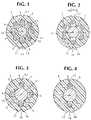
- FIGS. 1–4are cross-sectional views of cables of the invention taken perpendicularly to the axes of the cables;
- FIG. 5is a diagrammatic perspective view of the cable illustrated in FIG. 4 ;
- FIG. 6is an enlarged, fragmentary cross-section of a modified form of the cable illustrated in FIG. 2 ;
- FIG. 7is a greatly enlarged, fragmentary, cross-sectional view illustrating a jacket slot with a tight buffered optical fiber and water blocking yarns therein;
- FIG. 8illustrates in perspective the cable of FIG. 3 after the jacket has been cut at the grooves therein and the cable portions at each side of the cuts have been manually pulled away from the strength member to expose the optical fibers;
- FIGS. 9 and 10are enlarged, fragmentary, cross-sectional views of modifications of the embodiment shown in FIG. 1 in which the materials of the cable jacket and the up-jacket on the strength member are the same and join the cable jacket with the strength member up-jacket.
- FIGS. 1–4illustrate, in cross-section, embodiments of the cable of the invention comprising, respectively, eight, six, four and two optical fibers.
- the cablescan include a greater or lesser number of optical fibers, but normally, will not include more than twelve or less than two optical fibers.
- Each of the cables 1 – 4 illustrated in FIGS. 1–4has a tubular jacket 5 made of a plastic conventional in the art, such as polyvinylchloride or polyethylene. Since the cable of the invention can be used indoors as well as outdoors, preferably, the plastic is a plastic which will meet National Electric Code requirements for thickness, and flame propagation and which is low smoke producing. See, for example, cited U.S. Pat. No. 5,390,273.
- the diameters of the outer surface of the jackets 5are kept as small as possible consistent with the required protection of the optical fibers and the required size of the jacket slots hereinafter described.
- the diameter of the outer surface of the cable 1can be about 7.9 mm, and the diameter of the outer surfaces of the cables 2 – 4 can be about 6.9 mm.
- FIG. 1illustrates eight tight buffered optical fibers 6 of the type described hereinbefore in eight slots 7 in the jacket 5 which open inwardly toward a strength member 8 .
- Each of the tight buffered optical fibers 6can have, for example, a glass core encircled by one or more refracting layers which, in turn, are encircled by one or more protective layers of a protective material, such as a polymeric material.
- the outer diameter of each fiber 6can be on the order of about 0.6 mm to about 0.9 mm.
- the wall of the jacket 5extends radially from the strength member 8 to the outer surface of the jacket 5 , and plastic material of the jacket 5 forms the walls of each slot 7 and is disposed between the slots 7 and the outer surface of the jacket 5 .
- Portions 9 of the jacket 5engage the strength member 8 and connect the jacket 5 to the strength member 8 .
- the portions 9are at circumferentially opposite sides of each of the slots 7 .
- each slot 7has one tight buffered optical fiber 6 therein.
- each slot 7is selected in relation to the cross-sectional dimension of the optical fiber so that the fiber 6 can move longitudinally with respect to the jacket 5 .
- the slots 7can have a width w (see FIG. 2 ) of the order of 1.2 mm when the outer diameter of the optical fiber is on the order of about 0.6 mm to about 0.9 mm.
- the depth of each slot 7should also be greater than the diameter of the optical fibers and can also be on the order of 1.2 mm.
- the slots 7can contain a water blocking material, such as a water swellable powder 12 (see FIG. 6 ) or a thixotropic jelly known in the art.
- the fiber 6can be coated with a release agent of the type described in U.S. Pat. No. 6,137,936.
- the plastics used for the jacket 5 and the outer layer of the fibers 6can be selected from plastics which do not stick to each other.
- each of the slots 7can have more than one optical fiber therein, and if desired, the slots 7 can have optical fibers therein which are not tight buffered if the advantages of tight buffered optical fibers are not needed.
- the slots 7follow paths in the jacket 5 which are of alternating lay or S-Z lay as described and illustrated in said U.S. Pat. No. 5,390,273 for the buffer tubes 4 – 9 and as illustrated in FIG. 5 .
- the strength member 8 illustrated in FIG. 1comprises a core 10 and an encircling layer 11 of plastic, the latter being sometimes called an “up-jacket” and included, when necessary, to provide the desired spacing between the slots 7 when the core 10 need not have the diameter required for such spacing.
- the core 10is formed by a material of high tensile strength, e.g. a steel wire or rod or epoxy impregnated glass or aramid fibers.
- the core 10provides the required resistance to tensile forces, e.g. up to 600 pounds, encountered during handling, installation and suspension of the cable.
- the core 10is also able to withstand and resist compression and tension forces caused by temperature changes from ⁇ 50° C. to 85° C.
- the temperature coefficient of expansion and contraction of the core 10is less than such coefficient of the jacket 5 so as to reduce longitudinal expansion and contraction of the jacket 5 connected to the strength member 8 by the portions 9 .
- FIG. 1illustrates the cable 1 with a core 10 with an up-jacket layer 11 of plastic.
- the strength memberis a bare core 10 a of glass fibers which can be impregnated with an epoxy resin as is known in the art.
- Such a core 10 ahas high tensile strength and a low coefficient of expansion and contraction and is resistant to contraction forces.
- the material encircling the optical fibers 6 , the jacket 5 in the cable of the inventionshould have sufficient connection to the strength member 8 to prevent longitudinal and circumferential movement of such material (the jacket 5 ) with respect to forces applied to the cable by reason of handling of the cable, temperature changes and suspension of the cable.
- the major forcesnormally are the pulling forces during installation of a cable which cause shear stresses at the interface of the portions 9 and the strength member 8 or 10 a .
- shear stresseswill vary depending on the diameters of the cable components and on the installation methods and tools used. For example, if the optical fiber cable 3 illustrated in FIG.
- the adhesion between the portions 9 and the strength member 8 or 10 a for such a cablemust provide a resistance to movement of the portions 9 relative to the strength member 8 or 10 a which is greater than 0.97 N/mm 2 .
- such resistancemust be less than the yield or rupture strength of the material of the jacket 5 , i.e. should not exceed 90% of such strength and preferably, should not exceed 80% of such strength.
- the materials of the jacket 5 and of the strength member 8preferably are sized, treated and/or selected so that there is a connection between the portions 9 and the strength member 8 which, by adhesion and/or friction therebetween, prevents longitudinal movement between the jacket 5 and the strength member 8 or 10 a when the pulling force on the cable is up to 300 pounds but, nevertheless, permits separation of the jacket 5 from the strength member 8 with manual forces of not more than 100 pounds applied radially away from the strength member 8 or 10 a after the jacket 5 has been longitudinally cut along diametrically opposite lines.
- the manual force required to pull the jacket 5 away from the strength member 8 or 10 ais not more than about 20 pounds and does not exceed 75 pounds.
- the strength memberis made of metal or glass fibers and is bare, i.e. is a core 10 a without an encircling layer, and the jacket 5 is made of plastic
- the material of the jacket 5 and circumferential length of the portions 9 at the surface of the strength membercan be selected so that the desired resistance to longitudinal movement between the jacket 5 and the strength member 8 can be obtained by adhesion and/or the coefficient of friction between the jacket 5 material and the strength member material.
- the material of the jacket 5can be, for example, polyvinylchloride or polyethylene.
- the jacket portionscan be readily separated from the strength member by manual forces applied to the jacket radially of the cable axis.
- the desired resistance to such longitudinal movement and ease of separation of the jacket 5 from the strength member 8can be obtained by making the jacket 5 of a plastic which does not bond, or only weakly bonds, to the plastic of the up-jacket, or by coating the outer surface of the up-jacket 11 , or the inner surfaces of the portions 9 , with a release agent known in the art.
- the preferred release agentis the Miller Stephenson MS-143 DF, the release agent described in U.S. Pat. No. 6,137,936.
- Plastics which do not bond, or which only weakly bondinclude those which are immiscible and those which have different melt temperatures.
- Polar and non-polar plasticsare immiscible and, for example, the up-jacket 11 can be formed from a polar plastic and the jacket 5 can be formed from a non-polar plastic or vice versa.
- Combinations of such plastics which weakly adhereare polyvinylchloride (PVC) and polyethylene (PE), polypropylene (PP) and PVC, PP and polybutylene (PBT), PP and polyethylene terephthalate (PET), PE and PET and PE and PBT.
- the plastic with the higher melt temperaturewould be used for the up-jacket 11 and the plastic for the jacket 5 would have a lower melt temperature so that when it is applied it would not cause melting of the up-jacket material and significant mixing of the two plastics.
- PBTcould be used for the up-jacket 11 and PE or PP for the jacket 5 or PBT or PET as the up-jacket 11 and PVC as the jacket 5 .
- the strength member 8has an up-jacket 11 of plastic material which is the same as the plastic material of the jacket 5 , as shown in FIGS. 9 and 10 , the up-jacket 11 and jacket 5 can be co-extruded so that the portions 9 are integral with the up-jacket 11 .
- the circumferential lengths of the portions 9 , at the up-jacket portion 11should be selected so that the required resistance to longitudinal movement of the jacket portion 5 relative to the up-jacket portion 11 and the ease of separation of the jacket portion 5 from the up-jacket portion 11 by radially applied forces set forth hereinbefore are met.
- portions 9will rupture at the up-jacket portion 11 and will cause the jacket portion 5 to separate from the strength member 8 .
- the circumferential length of portions 9should also be selected so that when the pulling force on the cable is up to 300 pounds, the portions 9 will not separate from the up-jacket portion 11 .
- the force required to rupture the portions 9when the force is applied to the portions 9 in the direction parallel to the axis of the strength member 8 , is significantly greater than the force required to rupture the portions 9 when the force is applied to the portions 9 radially of the axis of the strength member 8 .
- the circumferential lengths of the portions 9 where they meet the up-jacket potion 11depend upon the plastic material used and the tensile force required to rupture such material. For example, if the jacket 5 and the up-jacket 11 are both made of polyethylene, the circumferential lengths of the portions 9 at the up-jacket portion 11 can be from about 0.1 mm to about 0.5 mm.
- the portions 9 in FIG. 9being of the smallest circumferential length, form a line of weakening, but if desired, the line of weakening can be radially outward of the up-jacket portion 11 and circumferentially adjacent the slot on duct 7 as illustrated in FIG. 10 .
- the portions 9can have a circumferential length such that they will not rupture with a force sufficient to rupture the jacket portion 5 at the lines of weakening 24 and 25 which are spaced radially outwardly from the portions 9 and which provide therebetween jacket material of a circumferential length less than the circumferential length of the portions 9 .
- two opposed lines of weakening 24 and 25are shown, it will be apparent that a single line of weakening 24 or 25 can be used.
- the cables of the inventionpreferably have one or more visible indicium at the outer surface of the jacket 5 .
- the outer surface of the jacket 5can have visible markings thereon or stripes of plastic different in color from the plastic of the remainder of the jacket 5 .
- the indiciaare physical modifications of the jacket 5 , not only to identify the positions of the slots 7 , but also to provide guides for tools for cutting the jacket 5 .
- the indiciaprovide diametrically opposite lines of weakening in the jacket 5 for providing exposure of all the optical fibers 6 at a cable end as described hereinafter.
- the jacket 5has two diametrically opposite, longitudinal, V-shaped grooves 13 and 14 which extend inwardly from the outer surface of the jacket 5 and which throughout their lengths radially overlie, a pair of diametrically opposite slots 7 and hence, the optical fibers therein.
- the bottom of each groove 13 and 14i.e. the portion of the groove which is nearest the axis 15 of the cables, lies on a line which extends radially from the axis 15 and intersects the cores of the optical fibers 6 in the slots 7 adjacent to the grooves 13 and 14 .
- grooves 13 and 14Although a greater number of similarly disposed grooves 13 and 14 could be used, e.g. a groove adjacent each slot 7 , two grooves 13 and 14 are normally sufficient. If it is desired to distinguish one of the grooves from the other of the grooves, the groove 14 can be visibly distinguished by one or more ridges or ribs 17 and 18 extending alongside the groove 14 and extending outwardly from the jacket 5 . Alternatively, or in addition, the grooves 13 and 14 can have different cross-sectional shapes, e.g. one can be V-shaped as shown and the other can be arcuate.
- water or moisture blocking materialcan be used in, or adjacent, the slots 7 for protecting the optical fibers 6 with respect to water and moisture.
- water blocking materialis well known in the art and includes water absorbing or water swellable powders, tapes and yarns, thixotropic gels and petroleum greases.
- FIG. 6is a fragmentary, cross-sectional view of a cable 2 a which is similar to the cable 2 , but which has water blocking materials therein.
- the core 10 a in FIG. 6can be the same as the core 10 a in FIG. 2 or can be twisted glass fibers or steel wires.
- the core 10 ais encircled by a plastic layer 11 which is encircled by a layer 19 of a known type of water swellable tape.
- the slots 7can contain a water blocking powder 12 of a known type, such powder 12 serving the dual function of providing moisture protection for the optical fibers 6 and of preventing sticking of the optical fibers 6 to the jacket 5 .
- FIG. 7is a greatly enlarged, fragmentary, cross-sectional view of a slot 7 with a tight buffered optical fiber 6 and water blocking yarns 20 therein.
- the yarns 20are of a known type which absorb moisture, and the yarns 20 can be either loosely received in the slot 7 or helically wrapped around the optical fiber 6 .
- the tight buffered optical fiber 6comprises a core 21 of glass, e.g. silica glass, doped or undoped, a layer or layers 22 which are normally applied by the manufacturer of the optical fiber and a buffering layer 23 of relatively soft plastic.
- the layer or layers 22comprises a cladding layer of glass having an index of refraction lower than the index of refraction of the core 21 .
- the buffering layer 23can include one or more layers of extruded plastic such as polyethylene, polypropylene, polyvinylchloride, nylon, ethylenevinylacetate or polyurethane.
- an optical fiber 6can be readily accessed intermediate the ends of a cable by cutting the jacket 5 axially along a line overlying the fiber 6 and radially from the outer surface of the jacket 5 to the slot 7 containing the fiber 6 to be accessed.
- the jacket 5can be axially cut along both grooves 13 and 14 and radially inwardly to the underlying slots 7 , and thereafter, since the bond of the portions 9 to the strength member core 10 a is manually frangible at the core 10 a , the portions of the jacket 5 at opposite sides of the grooves 13 and 14 can be manually and readily pulled apart to expose the end portions of all the optical fibers 6 in the cable 3 . In other words, with only two axial and radial cuts in the jacket 5 , the end portions of all the optical fibers 6 in the cable can be exposed.
- the structure of the cable of the inventionpermits a manufacturing process which is simpler than the process needed for manufacturing the stranded loose tube cable and the slotted core cable.
- the jacket and the fibersare simultaneously applied to the strength member, and in the case of S-Z stranding of the fibers around the strength member, reversal of the fiber pay-off reels is not required and the fibers are precisely aligned with the slots or ducts.
- the jacketbears indicia of the location of the slots or ducts, the indicia can be applied at the same time as the jacket is applied and the slots or ducts are formed, and the indicia will precisely follow the positions of the slots or ducts.
- the separate steps of manufacturing a slotted core before the fibers are inserted in the slots of a slotted core or manufacturing buffer tubes with fibers therein before the jacket is appliedare eliminated.
- an advantage of the process for the manufacture of the cable of the inventionis that the process can comprise only the following steps:
- the diecan also apply the identifying stripes to, or form the identifying grooves in, the jacket.
Landscapes
- Physics & Mathematics (AREA)
- General Physics & Mathematics (AREA)
- Optics & Photonics (AREA)
- Light Guides In General And Applications Therefor (AREA)
- Details Of Indoor Wiring (AREA)
- Mechanical Coupling Of Light Guides (AREA)
Abstract
Description
- (1) Manufacture of a central strength member preferably with a plastic up-jacket but, alternatively, without such up-jacket; and
- (2) Feeding the strength member and optical fibers through a die, which can be rotatable for S-Z stranding, which simultaneously extrudes the jacket material over the strength member, forms the slots or ducts and inserts the fibers in the slots or ducts. If the strength member is without an up-jacket, the strength member can have an up-jacket extruded thereover before or during the extrusion of the jacket material.
Claims (32)
Priority Applications (8)
| Application Number | Priority Date | Filing Date | Title |
|---|---|---|---|
| US10/992,459US7123801B2 (en) | 2004-11-18 | 2004-11-18 | Optical fiber cable with fiber receiving jacket ducts |
| BRPI0517760-0ABRPI0517760A (en) | 2004-11-18 | 2005-11-15 | fiber optic cable |
| CA2587364ACA2587364C (en) | 2004-11-18 | 2005-11-15 | Optical fiber cable with fiber receiving jacket ducts |
| PCT/US2005/041300WO2006055538A2 (en) | 2004-11-18 | 2005-11-15 | Optical fiber cable with fiber receiving jacket ducts |
| NZ555201ANZ555201A (en) | 2004-11-18 | 2005-11-15 | Optical fiber cable with fiber receiving jacket ducts |
| AU2005306625AAU2005306625B2 (en) | 2004-11-18 | 2005-11-15 | Optical fiber cable with fiber receiving jacket ducts |
| EP05851645AEP1812817A4 (en) | 2004-11-18 | 2005-11-15 | Optical fiber cable with fiber receiving jacket ducts |
| CNB2005800393090ACN100480761C (en) | 2004-11-18 | 2005-11-15 | Optical fiber cable with fiber receiving jacket ducts |
Applications Claiming Priority (1)
| Application Number | Priority Date | Filing Date | Title |
|---|---|---|---|
| US10/992,459US7123801B2 (en) | 2004-11-18 | 2004-11-18 | Optical fiber cable with fiber receiving jacket ducts |
Publications (2)
| Publication Number | Publication Date |
|---|---|
| US20060104579A1 US20060104579A1 (en) | 2006-05-18 |
| US7123801B2true US7123801B2 (en) | 2006-10-17 |
Family
ID=34956847
Family Applications (1)
| Application Number | Title | Priority Date | Filing Date |
|---|---|---|---|
| US10/992,459Expired - Fee RelatedUS7123801B2 (en) | 2004-11-18 | 2004-11-18 | Optical fiber cable with fiber receiving jacket ducts |
Country Status (8)
| Country | Link |
|---|---|
| US (1) | US7123801B2 (en) |
| EP (1) | EP1812817A4 (en) |
| CN (1) | CN100480761C (en) |
| AU (1) | AU2005306625B2 (en) |
| BR (1) | BRPI0517760A (en) |
| CA (1) | CA2587364C (en) |
| NZ (1) | NZ555201A (en) |
| WO (1) | WO2006055538A2 (en) |
Cited By (217)
| Publication number | Priority date | Publication date | Assignee | Title |
|---|---|---|---|---|
| US20070065075A1 (en)* | 2005-09-22 | 2007-03-22 | Alexander Berger | Segmented fiber optic sensor and method |
| US20070065070A1 (en)* | 2005-09-22 | 2007-03-22 | Alexander Berger | Segmented fiber optic sensor and method |
| US20090060428A1 (en)* | 2007-08-27 | 2009-03-05 | Julian Mullaney | Methods for Accessing a Fiber Within a Fiber Optic Cable to Splice Thereto and Tools for Use with the Same |
| US20090129734A1 (en)* | 2007-11-02 | 2009-05-21 | David Keller | Loose tube optical fiber cable design and method for making the same |
| US20100158456A1 (en)* | 2007-05-31 | 2010-06-24 | Willem Griffioen | Cable, And A Network And The Use Of Such A Cable |
| US20110229097A1 (en)* | 2010-03-19 | 2011-09-22 | Reginald Roberts | Optical usb cable with controlled fiber positioning |
| US8119916B2 (en) | 2009-03-02 | 2012-02-21 | Coleman Cable, Inc. | Flexible cable having a dual layer jacket |
| US20120063731A1 (en)* | 2010-09-10 | 2012-03-15 | Jonathan Gerald Fitz | Bundled optical fiber cable with grooved jacket |
| US20120224819A1 (en)* | 2004-11-22 | 2012-09-06 | Ellis Frampton E | Devices With Internal Flexibility Sipes, Including Siped Chambers For Footwear |
| USD669618S1 (en) | 2008-10-08 | 2012-10-23 | Nite Ize, Inc. | Flexible lighting device |
| USD669619S1 (en) | 2008-10-08 | 2012-10-23 | Nite Ize, Inc. | Flexible lighting device |
| US8362359B1 (en) | 2009-07-27 | 2013-01-29 | Superior Essex Communications Lp | Surface modified drop cable, method of making same, and drop cable assembly |
| USD675606S1 (en) | 2011-08-02 | 2013-02-05 | Nite Ize, Inc. | Cantilevered snap fit case |
| USD675605S1 (en) | 2011-08-02 | 2013-02-05 | Nite Ize, Inc. | Cantilevered snap fit case |
| US8387216B1 (en)* | 2008-10-08 | 2013-03-05 | Nite Ize, Inc. | Tie wrap for bundling objects |
| USD679701S1 (en) | 2011-08-02 | 2013-04-09 | Nite Ize, Inc. | Gripping attachment for a portable electronic device case |
| US20130121654A1 (en)* | 2011-11-10 | 2013-05-16 | Commscope, Inc. Of North Carolina | Miniaturized Optical Fiber Drop Cable |
| USD685189S1 (en) | 2011-08-02 | 2013-07-02 | Nite Ize, Inc. | Card holder attachment |
| US8582939B2 (en) | 2010-11-23 | 2013-11-12 | Corning Cable Systems Llc | Fiber optic cables with access features |
| US8582940B2 (en) | 2010-10-28 | 2013-11-12 | Corning Cable Systems Llc | Fiber optic cables with extruded access features and methods of making fiber optic cables |
| US8616422B2 (en) | 2011-08-02 | 2013-12-31 | Greg Adelman | Cantilevered snap fit case |
| US8620124B1 (en) | 2012-09-26 | 2013-12-31 | Corning Cable Systems Llc | Binder film for a fiber optic cable |
| US8670246B2 (en) | 2007-11-21 | 2014-03-11 | Frampton E. Ellis | Computers including an undiced semiconductor wafer with Faraday Cages and internal flexibility sipes |
| US8682124B2 (en) | 2011-10-13 | 2014-03-25 | Corning Cable Systems Llc | Access features of armored flat fiber optic cable |
| USD705210S1 (en) | 2011-08-02 | 2014-05-20 | Nite Ize, Inc. | Carrying case receiver |
| US8805144B1 (en) | 2013-09-24 | 2014-08-12 | Corning Optical Communications LLC | Stretchable fiber optic cable |
| US8806723B2 (en) | 2008-10-08 | 2014-08-19 | Nite Ize, Inc. | Tie wrap for bundling objects |
| USD714278S1 (en) | 2013-07-29 | 2014-09-30 | Nite Ize, Inc. | Mobile phone case |
| US8909014B2 (en) | 2012-04-27 | 2014-12-09 | Corning Cable Systems Llc | Fiber optic cable with access features and jacket-to-core coupling, and methods of making the same |
| US8913862B1 (en) | 2013-09-27 | 2014-12-16 | Corning Optical Communications LLC | Optical communication cable |
| US9073243B2 (en) | 2010-04-30 | 2015-07-07 | Corning Cable Systems Llc | Fiber optic cables with access features and methods of making fiber optic cables |
| US9075212B2 (en) | 2013-09-24 | 2015-07-07 | Corning Optical Communications LLC | Stretchable fiber optic cable |
| US9091830B2 (en) | 2012-09-26 | 2015-07-28 | Corning Cable Systems Llc | Binder film for a fiber optic cable |
| US9119127B1 (en) | 2012-12-05 | 2015-08-25 | At&T Intellectual Property I, Lp | Backhaul link for distributed antenna system |
| US9140867B1 (en) | 2013-08-09 | 2015-09-22 | Corning Optical Communications LLC | Armored optical fiber cable |
| US9154966B2 (en) | 2013-11-06 | 2015-10-06 | At&T Intellectual Property I, Lp | Surface-wave communications and methods thereof |
| US9176293B2 (en) | 2011-10-28 | 2015-11-03 | Corning Cable Systems Llc | Buffered fibers with access features |
| US9174781B2 (en) | 2008-10-08 | 2015-11-03 | Nite Ize, Inc. | Tie wrap for bundling objects |
| US9201208B2 (en) | 2011-10-27 | 2015-12-01 | Corning Cable Systems Llc | Cable having core, jacket and polymeric jacket access features located in the jacket |
| US9209902B2 (en) | 2013-12-10 | 2015-12-08 | At&T Intellectual Property I, L.P. | Quasi-optical coupler |
| USD745866S1 (en) | 2011-08-02 | 2015-12-22 | Nite Ize, Inc. | Cantilevered snap fit case |
| US9256043B2 (en) | 2012-02-03 | 2016-02-09 | Corning Cable Systems Llc | Strength member system for fiber optic cable |
| US9274302B2 (en) | 2011-10-13 | 2016-03-01 | Corning Cable Systems Llc | Fiber optic cables with extruded access features for access to a cable cavity |
| US9312919B1 (en) | 2014-10-21 | 2016-04-12 | At&T Intellectual Property I, Lp | Transmission device with impairment compensation and methods for use therewith |
| US9323022B2 (en) | 2012-10-08 | 2016-04-26 | Corning Cable Systems Llc | Methods of making and accessing cables having access features |
| US9461706B1 (en) | 2015-07-31 | 2016-10-04 | At&T Intellectual Property I, Lp | Method and apparatus for exchanging communication signals |
| US9490869B1 (en) | 2015-05-14 | 2016-11-08 | At&T Intellectual Property I, L.P. | Transmission medium having multiple cores and methods for use therewith |
| US9503189B2 (en) | 2014-10-10 | 2016-11-22 | At&T Intellectual Property I, L.P. | Method and apparatus for arranging communication sessions in a communication system |
| US9509415B1 (en) | 2015-06-25 | 2016-11-29 | At&T Intellectual Property I, L.P. | Methods and apparatus for inducing a fundamental wave mode on a transmission medium |
| US9520945B2 (en) | 2014-10-21 | 2016-12-13 | At&T Intellectual Property I, L.P. | Apparatus for providing communication services and methods thereof |
| US9525210B2 (en) | 2014-10-21 | 2016-12-20 | At&T Intellectual Property I, L.P. | Guided-wave transmission device with non-fundamental mode propagation and methods for use therewith |
| US9525524B2 (en) | 2013-05-31 | 2016-12-20 | At&T Intellectual Property I, L.P. | Remote distributed antenna system |
| USD774879S1 (en) | 2008-10-08 | 2016-12-27 | Nite Ize, Inc. | Tie wrap for bundling objects |
| US9531427B2 (en) | 2014-11-20 | 2016-12-27 | At&T Intellectual Property I, L.P. | Transmission device with mode division multiplexing and methods for use therewith |
| US9564947B2 (en) | 2014-10-21 | 2017-02-07 | At&T Intellectual Property I, L.P. | Guided-wave transmission device with diversity and methods for use therewith |
| US9577306B2 (en) | 2014-10-21 | 2017-02-21 | At&T Intellectual Property I, L.P. | Guided-wave transmission device and methods for use therewith |
| US9594226B2 (en) | 2013-10-18 | 2017-03-14 | Corning Optical Communications LLC | Optical fiber cable with reinforcement |
| US9608740B2 (en) | 2015-07-15 | 2017-03-28 | At&T Intellectual Property I, L.P. | Method and apparatus for launching a wave mode that mitigates interference |
| US9608692B2 (en) | 2015-06-11 | 2017-03-28 | At&T Intellectual Property I, L.P. | Repeater and methods for use therewith |
| US9615269B2 (en) | 2014-10-02 | 2017-04-04 | At&T Intellectual Property I, L.P. | Method and apparatus that provides fault tolerance in a communication network |
| US9628116B2 (en) | 2015-07-14 | 2017-04-18 | At&T Intellectual Property I, L.P. | Apparatus and methods for transmitting wireless signals |
| US9628854B2 (en) | 2014-09-29 | 2017-04-18 | At&T Intellectual Property I, L.P. | Method and apparatus for distributing content in a communication network |
| US9640850B2 (en) | 2015-06-25 | 2017-05-02 | At&T Intellectual Property I, L.P. | Methods and apparatus for inducing a non-fundamental wave mode on a transmission medium |
| US9653770B2 (en) | 2014-10-21 | 2017-05-16 | At&T Intellectual Property I, L.P. | Guided wave coupler, coupling module and methods for use therewith |
| US9654173B2 (en) | 2014-11-20 | 2017-05-16 | At&T Intellectual Property I, L.P. | Apparatus for powering a communication device and methods thereof |
| US9667317B2 (en) | 2015-06-15 | 2017-05-30 | At&T Intellectual Property I, L.P. | Method and apparatus for providing security using network traffic adjustments |
| US9680670B2 (en) | 2014-11-20 | 2017-06-13 | At&T Intellectual Property I, L.P. | Transmission device with channel equalization and control and methods for use therewith |
| US9685992B2 (en) | 2014-10-03 | 2017-06-20 | At&T Intellectual Property I, L.P. | Circuit panel network and methods thereof |
| US9692101B2 (en) | 2014-08-26 | 2017-06-27 | At&T Intellectual Property I, L.P. | Guided wave couplers for coupling electromagnetic waves between a waveguide surface and a surface of a wire |
| US9705561B2 (en) | 2015-04-24 | 2017-07-11 | At&T Intellectual Property I, L.P. | Directional coupling device and methods for use therewith |
| US9705571B2 (en) | 2015-09-16 | 2017-07-11 | At&T Intellectual Property I, L.P. | Method and apparatus for use with a radio distributed antenna system |
| US9722318B2 (en) | 2015-07-14 | 2017-08-01 | At&T Intellectual Property I, L.P. | Method and apparatus for coupling an antenna to a device |
| US9729197B2 (en) | 2015-10-01 | 2017-08-08 | At&T Intellectual Property I, L.P. | Method and apparatus for communicating network management traffic over a network |
| US9735833B2 (en) | 2015-07-31 | 2017-08-15 | At&T Intellectual Property I, L.P. | Method and apparatus for communications management in a neighborhood network |
| US9742462B2 (en) | 2014-12-04 | 2017-08-22 | At&T Intellectual Property I, L.P. | Transmission medium and communication interfaces and methods for use therewith |
| US9749013B2 (en) | 2015-03-17 | 2017-08-29 | At&T Intellectual Property I, L.P. | Method and apparatus for reducing attenuation of electromagnetic waves guided by a transmission medium |
| US9749053B2 (en) | 2015-07-23 | 2017-08-29 | At&T Intellectual Property I, L.P. | Node device, repeater and methods for use therewith |
| US9748626B2 (en) | 2015-05-14 | 2017-08-29 | At&T Intellectual Property I, L.P. | Plurality of cables having different cross-sectional shapes which are bundled together to form a transmission medium |
| US9755697B2 (en) | 2014-09-15 | 2017-09-05 | At&T Intellectual Property I, L.P. | Method and apparatus for sensing a condition in a transmission medium of electromagnetic waves |
| US9762289B2 (en) | 2014-10-14 | 2017-09-12 | At&T Intellectual Property I, L.P. | Method and apparatus for transmitting or receiving signals in a transportation system |
| US9769020B2 (en) | 2014-10-21 | 2017-09-19 | At&T Intellectual Property I, L.P. | Method and apparatus for responding to events affecting communications in a communication network |
| US9769128B2 (en) | 2015-09-28 | 2017-09-19 | At&T Intellectual Property I, L.P. | Method and apparatus for encryption of communications over a network |
| US9780834B2 (en) | 2014-10-21 | 2017-10-03 | At&T Intellectual Property I, L.P. | Method and apparatus for transmitting electromagnetic waves |
| US9793954B2 (en) | 2015-04-28 | 2017-10-17 | At&T Intellectual Property I, L.P. | Magnetic coupling device and methods for use therewith |
| US9793951B2 (en) | 2015-07-15 | 2017-10-17 | At&T Intellectual Property I, L.P. | Method and apparatus for launching a wave mode that mitigates interference |
| US9793955B2 (en) | 2015-04-24 | 2017-10-17 | At&T Intellectual Property I, Lp | Passive electrical coupling device and methods for use therewith |
| US9800327B2 (en) | 2014-11-20 | 2017-10-24 | At&T Intellectual Property I, L.P. | Apparatus for controlling operations of a communication device and methods thereof |
| US9820146B2 (en) | 2015-06-12 | 2017-11-14 | At&T Intellectual Property I, L.P. | Method and apparatus for authentication and identity management of communicating devices |
| US9838896B1 (en) | 2016-12-09 | 2017-12-05 | At&T Intellectual Property I, L.P. | Method and apparatus for assessing network coverage |
| US9836957B2 (en) | 2015-07-14 | 2017-12-05 | At&T Intellectual Property I, L.P. | Method and apparatus for communicating with premises equipment |
| US9847850B2 (en) | 2014-10-14 | 2017-12-19 | At&T Intellectual Property I, L.P. | Method and apparatus for adjusting a mode of communication in a communication network |
| US9847566B2 (en) | 2015-07-14 | 2017-12-19 | At&T Intellectual Property I, L.P. | Method and apparatus for adjusting a field of a signal to mitigate interference |
| US9853342B2 (en) | 2015-07-14 | 2017-12-26 | At&T Intellectual Property I, L.P. | Dielectric transmission medium connector and methods for use therewith |
| US9860075B1 (en) | 2016-08-26 | 2018-01-02 | At&T Intellectual Property I, L.P. | Method and communication node for broadband distribution |
| US9865911B2 (en) | 2015-06-25 | 2018-01-09 | At&T Intellectual Property I, L.P. | Waveguide system for slot radiating first electromagnetic waves that are combined into a non-fundamental wave mode second electromagnetic wave on a transmission medium |
| US9866309B2 (en) | 2015-06-03 | 2018-01-09 | At&T Intellectual Property I, Lp | Host node device and methods for use therewith |
| US9871283B2 (en) | 2015-07-23 | 2018-01-16 | At&T Intellectual Property I, Lp | Transmission medium having a dielectric core comprised of plural members connected by a ball and socket configuration |
| US9871282B2 (en) | 2015-05-14 | 2018-01-16 | At&T Intellectual Property I, L.P. | At least one transmission medium having a dielectric surface that is covered at least in part by a second dielectric |
| US9876264B2 (en) | 2015-10-02 | 2018-01-23 | At&T Intellectual Property I, Lp | Communication system, guided wave switch and methods for use therewith |
| US9876570B2 (en) | 2015-02-20 | 2018-01-23 | At&T Intellectual Property I, Lp | Guided-wave transmission device with non-fundamental mode propagation and methods for use therewith |
| US9876605B1 (en) | 2016-10-21 | 2018-01-23 | At&T Intellectual Property I, L.P. | Launcher and coupling system to support desired guided wave mode |
| US9882277B2 (en) | 2015-10-02 | 2018-01-30 | At&T Intellectual Property I, Lp | Communication device and antenna assembly with actuated gimbal mount |
| US9882257B2 (en) | 2015-07-14 | 2018-01-30 | At&T Intellectual Property I, L.P. | Method and apparatus for launching a wave mode that mitigates interference |
| US9893795B1 (en) | 2016-12-07 | 2018-02-13 | At&T Intellectual Property I, Lp | Method and repeater for broadband distribution |
| US9904535B2 (en) | 2015-09-14 | 2018-02-27 | At&T Intellectual Property I, L.P. | Method and apparatus for distributing software |
| US9906269B2 (en) | 2014-09-17 | 2018-02-27 | At&T Intellectual Property I, L.P. | Monitoring and mitigating conditions in a communication network |
| US9912419B1 (en) | 2016-08-24 | 2018-03-06 | At&T Intellectual Property I, L.P. | Method and apparatus for managing a fault in a distributed antenna system |
| US9912381B2 (en) | 2015-06-03 | 2018-03-06 | At&T Intellectual Property I, Lp | Network termination and methods for use therewith |
| US9912027B2 (en) | 2015-07-23 | 2018-03-06 | At&T Intellectual Property I, L.P. | Method and apparatus for exchanging communication signals |
| US9911020B1 (en) | 2016-12-08 | 2018-03-06 | At&T Intellectual Property I, L.P. | Method and apparatus for tracking via a radio frequency identification device |
| US9913139B2 (en) | 2015-06-09 | 2018-03-06 | At&T Intellectual Property I, L.P. | Signal fingerprinting for authentication of communicating devices |
| US9917341B2 (en) | 2015-05-27 | 2018-03-13 | At&T Intellectual Property I, L.P. | Apparatus and method for launching electromagnetic waves and for modifying radial dimensions of the propagating electromagnetic waves |
| US9927517B1 (en) | 2016-12-06 | 2018-03-27 | At&T Intellectual Property I, L.P. | Apparatus and methods for sensing rainfall |
| US9948354B2 (en) | 2015-04-28 | 2018-04-17 | At&T Intellectual Property I, L.P. | Magnetic coupling device with reflective plate and methods for use therewith |
| US9948333B2 (en) | 2015-07-23 | 2018-04-17 | At&T Intellectual Property I, L.P. | Method and apparatus for wireless communications to mitigate interference |
| US9954287B2 (en) | 2014-11-20 | 2018-04-24 | At&T Intellectual Property I, L.P. | Apparatus for converting wireless signals and electromagnetic waves and methods thereof |
| US9967173B2 (en) | 2015-07-31 | 2018-05-08 | At&T Intellectual Property I, L.P. | Method and apparatus for authentication and identity management of communicating devices |
| US9973940B1 (en) | 2017-02-27 | 2018-05-15 | At&T Intellectual Property I, L.P. | Apparatus and methods for dynamic impedance matching of a guided wave launcher |
| US9991580B2 (en) | 2016-10-21 | 2018-06-05 | At&T Intellectual Property I, L.P. | Launcher and coupling system for guided wave mode cancellation |
| US9997819B2 (en) | 2015-06-09 | 2018-06-12 | At&T Intellectual Property I, L.P. | Transmission medium and method for facilitating propagation of electromagnetic waves via a core |
| US9998870B1 (en) | 2016-12-08 | 2018-06-12 | At&T Intellectual Property I, L.P. | Method and apparatus for proximity sensing |
| US9999038B2 (en) | 2013-05-31 | 2018-06-12 | At&T Intellectual Property I, L.P. | Remote distributed antenna system |
| US10009065B2 (en) | 2012-12-05 | 2018-06-26 | At&T Intellectual Property I, L.P. | Backhaul link for distributed antenna system |
| US10009063B2 (en) | 2015-09-16 | 2018-06-26 | At&T Intellectual Property I, L.P. | Method and apparatus for use with a radio distributed antenna system having an out-of-band reference signal |
| US10009901B2 (en) | 2015-09-16 | 2018-06-26 | At&T Intellectual Property I, L.P. | Method, apparatus, and computer-readable storage medium for managing utilization of wireless resources between base stations |
| US10009067B2 (en) | 2014-12-04 | 2018-06-26 | At&T Intellectual Property I, L.P. | Method and apparatus for configuring a communication interface |
| US10020844B2 (en) | 2016-12-06 | 2018-07-10 | T&T Intellectual Property I, L.P. | Method and apparatus for broadcast communication via guided waves |
| US10020587B2 (en) | 2015-07-31 | 2018-07-10 | At&T Intellectual Property I, L.P. | Radial antenna and methods for use therewith |
| US10027397B2 (en) | 2016-12-07 | 2018-07-17 | At&T Intellectual Property I, L.P. | Distributed antenna system and methods for use therewith |
| US10033108B2 (en) | 2015-07-14 | 2018-07-24 | At&T Intellectual Property I, L.P. | Apparatus and methods for generating an electromagnetic wave having a wave mode that mitigates interference |
| US10033107B2 (en) | 2015-07-14 | 2018-07-24 | At&T Intellectual Property I, L.P. | Method and apparatus for coupling an antenna to a device |
| US10044409B2 (en) | 2015-07-14 | 2018-08-07 | At&T Intellectual Property I, L.P. | Transmission medium and methods for use therewith |
| US10051629B2 (en) | 2015-09-16 | 2018-08-14 | At&T Intellectual Property I, L.P. | Method and apparatus for use with a radio distributed antenna system having an in-band reference signal |
| US10051483B2 (en) | 2015-10-16 | 2018-08-14 | At&T Intellectual Property I, L.P. | Method and apparatus for directing wireless signals |
| US10069535B2 (en) | 2016-12-08 | 2018-09-04 | At&T Intellectual Property I, L.P. | Apparatus and methods for launching electromagnetic waves having a certain electric field structure |
| US10074890B2 (en) | 2015-10-02 | 2018-09-11 | At&T Intellectual Property I, L.P. | Communication device and antenna with integrated light assembly |
| US10079661B2 (en) | 2015-09-16 | 2018-09-18 | At&T Intellectual Property I, L.P. | Method and apparatus for use with a radio distributed antenna system having a clock reference |
| US10090606B2 (en) | 2015-07-15 | 2018-10-02 | At&T Intellectual Property I, L.P. | Antenna system with dielectric array and methods for use therewith |
| US10090594B2 (en) | 2016-11-23 | 2018-10-02 | At&T Intellectual Property I, L.P. | Antenna system having structural configurations for assembly |
| US10103422B2 (en) | 2016-12-08 | 2018-10-16 | At&T Intellectual Property I, L.P. | Method and apparatus for mounting network devices |
| US10103801B2 (en) | 2015-06-03 | 2018-10-16 | At&T Intellectual Property I, L.P. | Host node device and methods for use therewith |
| US10136434B2 (en) | 2015-09-16 | 2018-11-20 | At&T Intellectual Property I, L.P. | Method and apparatus for use with a radio distributed antenna system having an ultra-wideband control channel |
| US10135147B2 (en) | 2016-10-18 | 2018-11-20 | At&T Intellectual Property I, L.P. | Apparatus and methods for launching guided waves via an antenna |
| US10135146B2 (en) | 2016-10-18 | 2018-11-20 | At&T Intellectual Property I, L.P. | Apparatus and methods for launching guided waves via circuits |
| US10135145B2 (en) | 2016-12-06 | 2018-11-20 | At&T Intellectual Property I, L.P. | Apparatus and methods for generating an electromagnetic wave along a transmission medium |
| US10139820B2 (en) | 2016-12-07 | 2018-11-27 | At&T Intellectual Property I, L.P. | Method and apparatus for deploying equipment of a communication system |
| US10142086B2 (en) | 2015-06-11 | 2018-11-27 | At&T Intellectual Property I, L.P. | Repeater and methods for use therewith |
| US10144036B2 (en) | 2015-01-30 | 2018-12-04 | At&T Intellectual Property I, L.P. | Method and apparatus for mitigating interference affecting a propagation of electromagnetic waves guided by a transmission medium |
| US10148016B2 (en) | 2015-07-14 | 2018-12-04 | At&T Intellectual Property I, L.P. | Apparatus and methods for communicating utilizing an antenna array |
| US10154493B2 (en) | 2015-06-03 | 2018-12-11 | At&T Intellectual Property I, L.P. | Network termination and methods for use therewith |
| US10168695B2 (en) | 2016-12-07 | 2019-01-01 | At&T Intellectual Property I, L.P. | Method and apparatus for controlling an unmanned aircraft |
| US10170840B2 (en) | 2015-07-14 | 2019-01-01 | At&T Intellectual Property I, L.P. | Apparatus and methods for sending or receiving electromagnetic signals |
| US10178445B2 (en) | 2016-11-23 | 2019-01-08 | At&T Intellectual Property I, L.P. | Methods, devices, and systems for load balancing between a plurality of waveguides |
| US10205655B2 (en) | 2015-07-14 | 2019-02-12 | At&T Intellectual Property I, L.P. | Apparatus and methods for communicating utilizing an antenna array and multiple communication paths |
| US10224634B2 (en) | 2016-11-03 | 2019-03-05 | At&T Intellectual Property I, L.P. | Methods and apparatus for adjusting an operational characteristic of an antenna |
| US10225025B2 (en) | 2016-11-03 | 2019-03-05 | At&T Intellectual Property I, L.P. | Method and apparatus for detecting a fault in a communication system |
| US10243784B2 (en) | 2014-11-20 | 2019-03-26 | At&T Intellectual Property I, L.P. | System for generating topology information and methods thereof |
| US10243270B2 (en) | 2016-12-07 | 2019-03-26 | At&T Intellectual Property I, L.P. | Beam adaptive multi-feed dielectric antenna system and methods for use therewith |
| US10264586B2 (en) | 2016-12-09 | 2019-04-16 | At&T Mobility Ii Llc | Cloud-based packet controller and methods for use therewith |
| US10291311B2 (en) | 2016-09-09 | 2019-05-14 | At&T Intellectual Property I, L.P. | Method and apparatus for mitigating a fault in a distributed antenna system |
| US10291334B2 (en) | 2016-11-03 | 2019-05-14 | At&T Intellectual Property I, L.P. | System for detecting a fault in a communication system |
| US10298293B2 (en) | 2017-03-13 | 2019-05-21 | At&T Intellectual Property I, L.P. | Apparatus of communication utilizing wireless network devices |
| US10305190B2 (en) | 2016-12-01 | 2019-05-28 | At&T Intellectual Property I, L.P. | Reflecting dielectric antenna system and methods for use therewith |
| US10312567B2 (en) | 2016-10-26 | 2019-06-04 | At&T Intellectual Property I, L.P. | Launcher with planar strip antenna and methods for use therewith |
| US10320586B2 (en) | 2015-07-14 | 2019-06-11 | At&T Intellectual Property I, L.P. | Apparatus and methods for generating non-interfering electromagnetic waves on an insulated transmission medium |
| US10326689B2 (en) | 2016-12-08 | 2019-06-18 | At&T Intellectual Property I, L.P. | Method and system for providing alternative communication paths |
| US10326494B2 (en) | 2016-12-06 | 2019-06-18 | At&T Intellectual Property I, L.P. | Apparatus for measurement de-embedding and methods for use therewith |
| US10340573B2 (en) | 2016-10-26 | 2019-07-02 | At&T Intellectual Property I, L.P. | Launcher with cylindrical coupling device and methods for use therewith |
| US10340600B2 (en) | 2016-10-18 | 2019-07-02 | At&T Intellectual Property I, L.P. | Apparatus and methods for launching guided waves via plural waveguide systems |
| US10341142B2 (en) | 2015-07-14 | 2019-07-02 | At&T Intellectual Property I, L.P. | Apparatus and methods for generating non-interfering electromagnetic waves on an uninsulated conductor |
| US10340603B2 (en) | 2016-11-23 | 2019-07-02 | At&T Intellectual Property I, L.P. | Antenna system having shielded structural configurations for assembly |
| US10340983B2 (en) | 2016-12-09 | 2019-07-02 | At&T Intellectual Property I, L.P. | Method and apparatus for surveying remote sites via guided wave communications |
| US10340601B2 (en) | 2016-11-23 | 2019-07-02 | At&T Intellectual Property I, L.P. | Multi-antenna system and methods for use therewith |
| US10348391B2 (en) | 2015-06-03 | 2019-07-09 | At&T Intellectual Property I, L.P. | Client node device with frequency conversion and methods for use therewith |
| US10355367B2 (en) | 2015-10-16 | 2019-07-16 | At&T Intellectual Property I, L.P. | Antenna structure for exchanging wireless signals |
| US10361489B2 (en) | 2016-12-01 | 2019-07-23 | At&T Intellectual Property I, L.P. | Dielectric dish antenna system and methods for use therewith |
| US10359749B2 (en) | 2016-12-07 | 2019-07-23 | At&T Intellectual Property I, L.P. | Method and apparatus for utilities management via guided wave communication |
| US10374316B2 (en) | 2016-10-21 | 2019-08-06 | At&T Intellectual Property I, L.P. | System and dielectric antenna with non-uniform dielectric |
| US10382976B2 (en) | 2016-12-06 | 2019-08-13 | At&T Intellectual Property I, L.P. | Method and apparatus for managing wireless communications based on communication paths and network device positions |
| US10389029B2 (en) | 2016-12-07 | 2019-08-20 | At&T Intellectual Property I, L.P. | Multi-feed dielectric antenna system with core selection and methods for use therewith |
| US10389037B2 (en) | 2016-12-08 | 2019-08-20 | At&T Intellectual Property I, L.P. | Apparatus and methods for selecting sections of an antenna array and use therewith |
| US10396887B2 (en) | 2015-06-03 | 2019-08-27 | At&T Intellectual Property I, L.P. | Client node device and methods for use therewith |
| US10411356B2 (en) | 2016-12-08 | 2019-09-10 | At&T Intellectual Property I, L.P. | Apparatus and methods for selectively targeting communication devices with an antenna array |
| US10411920B2 (en) | 2014-11-20 | 2019-09-10 | At&T Intellectual Property I, L.P. | Methods and apparatus for inducing electromagnetic waves within pathways of a cable |
| US10439675B2 (en) | 2016-12-06 | 2019-10-08 | At&T Intellectual Property I, L.P. | Method and apparatus for repeating guided wave communication signals |
| US10446936B2 (en) | 2016-12-07 | 2019-10-15 | At&T Intellectual Property I, L.P. | Multi-feed dielectric antenna system and methods for use therewith |
| USD863945S1 (en) | 2008-10-08 | 2019-10-22 | Nite Ize, Inc. | Tie |
| USD863946S1 (en) | 2008-10-08 | 2019-10-22 | Nite Ize, Inc. | Tie |
| RU2707655C1 (en)* | 2016-08-04 | 2019-11-28 | Фудзикура Лтд. | Fiber-optic cable |
| US10498044B2 (en) | 2016-11-03 | 2019-12-03 | At&T Intellectual Property I, L.P. | Apparatus for configuring a surface of an antenna |
| US10505252B2 (en) | 2014-11-20 | 2019-12-10 | At&T Intellectual Property I, L.P. | Communication system having a coupler for guiding electromagnetic waves through interstitial areas formed by a plurality of stranded uninsulated conductors and method of use |
| US10505249B2 (en) | 2014-11-20 | 2019-12-10 | At&T Intellectual Property I, L.P. | Communication system having a cable with a plurality of stranded uninsulated conductors forming interstitial areas for guiding electromagnetic waves therein and method of use |
| US10505248B2 (en) | 2014-11-20 | 2019-12-10 | At&T Intellectual Property I, L.P. | Communication cable having a plurality of uninsulated conductors forming interstitial areas for propagating electromagnetic waves therein and method of use |
| US10505250B2 (en) | 2014-11-20 | 2019-12-10 | At&T Intellectual Property I, L.P. | Communication system having a cable with a plurality of stranded uninsulated conductors forming interstitial areas for propagating guided wave modes therein and methods of use |
| US10516555B2 (en) | 2014-11-20 | 2019-12-24 | At&T Intellectual Property I, L.P. | Methods and apparatus for creating interstitial areas in a cable |
| US10530505B2 (en) | 2016-12-08 | 2020-01-07 | At&T Intellectual Property I, L.P. | Apparatus and methods for launching electromagnetic waves along a transmission medium |
| US10535928B2 (en) | 2016-11-23 | 2020-01-14 | At&T Intellectual Property I, L.P. | Antenna system and methods for use therewith |
| US10547348B2 (en) | 2016-12-07 | 2020-01-28 | At&T Intellectual Property I, L.P. | Method and apparatus for switching transmission mediums in a communication system |
| US10554454B2 (en) | 2014-11-20 | 2020-02-04 | At&T Intellectual Property I, L.P. | Methods and apparatus for inducing electromagnetic waves in a cable |
| US10601494B2 (en) | 2016-12-08 | 2020-03-24 | At&T Intellectual Property I, L.P. | Dual-band communication device and method for use therewith |
| US10637149B2 (en) | 2016-12-06 | 2020-04-28 | At&T Intellectual Property I, L.P. | Injection molded dielectric antenna and methods for use therewith |
| US10650940B2 (en) | 2015-05-15 | 2020-05-12 | At&T Intellectual Property I, L.P. | Transmission medium having a conductive material and methods for use therewith |
| US10665942B2 (en) | 2015-10-16 | 2020-05-26 | At&T Intellectual Property I, L.P. | Method and apparatus for adjusting wireless communications |
| US10679767B2 (en) | 2015-05-15 | 2020-06-09 | At&T Intellectual Property I, L.P. | Transmission medium having a conductive material and methods for use therewith |
| US10694379B2 (en) | 2016-12-06 | 2020-06-23 | At&T Intellectual Property I, L.P. | Waveguide system with device-based authentication and methods for use therewith |
| US10727599B2 (en) | 2016-12-06 | 2020-07-28 | At&T Intellectual Property I, L.P. | Launcher with slot antenna and methods for use therewith |
| US10755542B2 (en) | 2016-12-06 | 2020-08-25 | At&T Intellectual Property I, L.P. | Method and apparatus for surveillance via guided wave communication |
| US10777873B2 (en) | 2016-12-08 | 2020-09-15 | At&T Intellectual Property I, L.P. | Method and apparatus for mounting network devices |
| US10784670B2 (en) | 2015-07-23 | 2020-09-22 | At&T Intellectual Property I, L.P. | Antenna support for aligning an antenna |
| US10811767B2 (en) | 2016-10-21 | 2020-10-20 | At&T Intellectual Property I, L.P. | System and dielectric antenna with convex dielectric radome |
| US10819035B2 (en) | 2016-12-06 | 2020-10-27 | At&T Intellectual Property I, L.P. | Launcher with helical antenna and methods for use therewith |
| US10916969B2 (en) | 2016-12-08 | 2021-02-09 | At&T Intellectual Property I, L.P. | Method and apparatus for providing power using an inductive coupling |
| US10938108B2 (en) | 2016-12-08 | 2021-03-02 | At&T Intellectual Property I, L.P. | Frequency selective multi-feed dielectric antenna system and methods for use therewith |
| US11025460B2 (en) | 2014-11-20 | 2021-06-01 | At&T Intellectual Property I, L.P. | Methods and apparatus for accessing interstitial areas of a cable |
| US11032819B2 (en) | 2016-09-15 | 2021-06-08 | At&T Intellectual Property I, L.P. | Method and apparatus for use with a radio distributed antenna system having a control channel reference signal |
| US11287589B2 (en) | 2012-09-26 | 2022-03-29 | Corning Optical Communications LLC | Binder film for a fiber optic cable |
| US12290134B2 (en) | 2004-11-22 | 2025-05-06 | Frampton E. Ellis | Footwear or orthotic sole with microprocessor control of a structural or support element with magnetorheological fluid |
Families Citing this family (30)
| Publication number | Priority date | Publication date | Assignee | Title |
|---|---|---|---|---|
| US20080004903A1 (en)* | 2006-06-29 | 2008-01-03 | Searete Llc, A Limited Liability Corporation Of The State Of Delaware | Enhanced communication link for patient diagnosis and treatment |
| US20080208635A1 (en)* | 2006-06-29 | 2008-08-28 | Searete Llc, | Data maintenance via patient monitoring technique |
| US20080000995A1 (en)* | 2006-06-29 | 2008-01-03 | Searete Llc, A Limited Liability Corporation Of The State Of Delaware | Enhanced communication link for patient diagnosis and treatment |
| US20080077447A1 (en)* | 2006-06-29 | 2008-03-27 | Searete Llc, A Limited Liability Corporation Of The State Of Delaware | Enhanced communication link for patient diagnosis and treatment |
| US20080059246A1 (en)* | 2006-06-29 | 2008-03-06 | Searete Llc, A Limited Liability Corporation Of State Of Delaware | Verification technique for patient diagnosis and treatment |
| DE102006031547A1 (en)* | 2006-07-07 | 2008-01-10 | CCS Technology, Inc., Wilmington | Optical cable and method of making an optical cable |
| BRPI0823076A2 (en)* | 2008-09-19 | 2015-06-16 | Prysmian Spa | Telecommunication cable, buffered microstructured optical fiber. |
| US12163394B2 (en) | 2009-04-17 | 2024-12-10 | Schlumberger Technology Corporation | Reduced torque wireline cable |
| US11978571B2 (en) | 2013-05-03 | 2024-05-07 | Christopher M. Rey | Method of coiling a superconducting cable with clocking feature |
| US11133120B2 (en)* | 2014-04-30 | 2021-09-28 | Christopher Mark Rey | Superconductor cable or superconductor cable-in-conduit-conductor with clocking feature |
| US9605779B2 (en)* | 2013-08-02 | 2017-03-28 | Oceaneering International, Inc. | Extruded encapsulated fillers to provide crush protection |
| CN103744153B (en)* | 2014-01-02 | 2015-09-09 | 长飞光纤光缆股份有限公司 | An emergency lighting optical cable and an emergency device using the optical cable |
| US9625670B2 (en)* | 2014-03-21 | 2017-04-18 | Verizon Patent And Licensing Inc. | Air jetted micro-cable with super low resistance and dramatically improved for air blockage |
| CN104375246A (en)* | 2014-11-05 | 2015-02-25 | 宁夏宏安信息技术有限公司 | Communication optical cable |
| CN105261417B (en)* | 2015-11-10 | 2016-09-07 | 山东泉兴银桥光电缆科技发展有限公司 | A kind of high-strength light cable |
| CN105225746B (en)* | 2015-11-10 | 2016-11-09 | 山东泉兴银桥光电缆科技发展有限公司 | A kind of composite optical cable |
| US10310209B2 (en)* | 2016-03-31 | 2019-06-04 | Ofs Fitel, Llc | Tight-buffered optical fiber having improved fiber access |
| CN109791264B (en)* | 2016-10-04 | 2021-06-15 | 住友电气工业株式会社 | Slotted rods and fiber optic cables |
| EP3629432A1 (en)* | 2018-09-25 | 2020-04-01 | Nokia Shanghai Bell Co., Ltd. | Apparatus, method and system for electrical interconnection |
| MX2021008412A (en)* | 2019-01-10 | 2021-10-13 | Ppc Broadband Inc | LINEAR MEMBERS WITH ANNULAR AND AXIAL SLOTS. |
| EP3745425B1 (en)* | 2019-05-31 | 2022-12-21 | Aptiv Technologies Limited | Communications cables for autonomous vehicles |
| GB2599553B (en) | 2019-06-28 | 2025-03-26 | Schlumberger Technology Bv | Stranded fiber-optic cable |
| CN114026658A (en) | 2019-06-28 | 2022-02-08 | 斯伦贝谢技术有限公司 | Mechanically Responsive Optical Fiber Wire Assemblies |
| EP3923053B1 (en)* | 2020-06-13 | 2025-02-12 | Sterlite Technologies Limited | Ribbed and grooved cable having embedded strength member with water blocking coating |
| CN112648541A (en)* | 2020-11-25 | 2021-04-13 | 宁波城市阳光环境建设工程有限公司 | BIM-based pipeline detection method and pipeline structure thereof |
| WO2022261390A1 (en) | 2021-06-10 | 2022-12-15 | Schlumberger Technology Corporation | Electro-optical wireline cables |
| CN114035291B (en)* | 2021-11-25 | 2023-11-24 | 长飞光纤光缆股份有限公司 | Optical fiber sleeve unit and impact-resistant optical cable |
| US11619787B1 (en) | 2021-12-28 | 2023-04-04 | Sterlite Technologies Limited | Embedded strength member for optical fiber cables and manufacturing method thereof |
| CN114185141B (en)* | 2022-02-15 | 2022-06-10 | 长飞光纤光缆股份有限公司 | Framework groove type optical cable framework processing method and device and framework groove type optical cable |
| CN115508963B (en)* | 2022-09-29 | 2025-04-01 | 长飞光纤光缆股份有限公司 | Optical unit with easy-to-open and strip loose sleeve, preparation method thereof and optical cable |
Citations (25)
| Publication number | Priority date | Publication date | Assignee | Title |
|---|---|---|---|---|
| GB2114771A (en)* | 1982-02-15 | 1983-08-24 | Bicc Plc | Optical cable manufacture |
| US4408828A (en) | 1979-11-22 | 1983-10-11 | Noane Georges Le | Optical fibre submarine cable |
| US4730894A (en) | 1986-03-27 | 1988-03-15 | American Telephone And Telegraph Company, At&T Bell Laboratories | Optical fiber cable having a prefabricated strength system and methods of making |
| EP0284900A2 (en) | 1987-03-31 | 1988-10-05 | AT&T Corp. | Optical fiber building cables |
| EP0297409A2 (en)* | 1987-06-30 | 1989-01-04 | PIRELLI CAVI S.p.A. | Optical fiber cable |
| US4899988A (en) | 1985-08-28 | 1990-02-13 | Madison Lightwave Systems, Inc. | Fiber optic cable placing equipment |
| US4902097A (en)* | 1986-06-17 | 1990-02-20 | Stc Plc | Optical fibre cables |
| US5180890A (en) | 1991-03-03 | 1993-01-19 | Independent Cable, Inc. | Communications transmission cable |
| US5193134A (en) | 1991-03-08 | 1993-03-09 | Pirelli Cavi S.P.A. | Grooved-core cable for use with ribbon optical fibres and process to make the same |
| US5210813A (en) | 1991-01-17 | 1993-05-11 | Siemens Aktiengesellschaft | Optical cable and method for manufacturing the optical cable |
| US5218659A (en)* | 1989-07-06 | 1993-06-08 | Siemens Aktiengesellschaft | Optical communications cable |
| US5222178A (en) | 1992-07-17 | 1993-06-22 | Hughes Aircraft Company | High density fiber optic cable packaging |
| US5388175A (en) | 1994-01-25 | 1995-02-07 | Siecor Corporation | Optical cable having powder embedded in plastic surfaces |
| US5390273A (en) | 1992-04-02 | 1995-02-14 | Pirelli Cable Corporation | Flame resistant optical fiber cable with optical fibers loosely enclosed in tubes |
| US5420955A (en) | 1994-06-22 | 1995-05-30 | Siecor Corporation | Optical cables having U-shaped carriers exhibiting enhanced crush performance |
| DE4401079A1 (en) | 1994-01-15 | 1995-07-20 | Nokia Kabel Gmbh | Optical fibre cable |
| US5440659A (en) | 1993-09-30 | 1995-08-08 | At&T Corp. | Method for fabricating a fiber optic cable having improved polarization mode dispersion (PMD) performance |
| FR2722029A1 (en) | 1994-07-01 | 1996-01-05 | Alcatel Cable | Composite electrical supply and optical fibre cable for telecommunications or domestic applications |
| US5509097A (en) | 1994-04-07 | 1996-04-16 | Pirelli Cable Corporation | Optical fiber core and cable with reinforced buffer tube loosely enclosing optical fibers |
| US5542019A (en) | 1992-03-03 | 1996-07-30 | Siemens Aktiengesellschaft | Optical cable and process for the manufacture thereof |
| US5668912A (en) | 1996-02-07 | 1997-09-16 | Alcatel Na Cable Systems, Inc. | Rectangular optical fiber cable |
| US5802231A (en) | 1996-03-12 | 1998-09-01 | Nippon Telegraph And Telephone Corporation | Flat optical fiber cable |
| US6137936A (en) | 1999-07-22 | 2000-10-24 | Pirelli Cables And Systems Llc | Optical fiber cable with single strength member in cable outer jacket |
| US6654525B2 (en)* | 2001-10-10 | 2003-11-25 | Alcatel | Central strength member with reduced radial stiffness |
| US20060140556A1 (en)* | 2002-08-10 | 2006-06-29 | Brown George H P | Signal transmitting cable |
Family Cites Families (1)
| Publication number | Priority date | Publication date | Assignee | Title |
|---|---|---|---|---|
| CN2466672Y (en)* | 2001-02-26 | 2001-12-19 | 江苏亨通光电股份有限公司 | Semi-tight sleeve optic fibre optic cable |
- 2004
- 2004-11-18USUS10/992,459patent/US7123801B2/ennot_activeExpired - Fee Related
- 2005
- 2005-11-15CACA2587364Apatent/CA2587364C/ennot_activeExpired - Fee Related
- 2005-11-15EPEP05851645Apatent/EP1812817A4/ennot_activeWithdrawn
- 2005-11-15BRBRPI0517760-0Apatent/BRPI0517760A/ennot_activeIP Right Cessation
- 2005-11-15NZNZ555201Apatent/NZ555201A/ennot_activeIP Right Cessation
- 2005-11-15WOPCT/US2005/041300patent/WO2006055538A2/enactiveApplication Filing
- 2005-11-15AUAU2005306625Apatent/AU2005306625B2/ennot_activeCeased
- 2005-11-15CNCNB2005800393090Apatent/CN100480761C/ennot_activeExpired - Fee Related
Patent Citations (26)
| Publication number | Priority date | Publication date | Assignee | Title |
|---|---|---|---|---|
| US4408828A (en) | 1979-11-22 | 1983-10-11 | Noane Georges Le | Optical fibre submarine cable |
| GB2114771A (en)* | 1982-02-15 | 1983-08-24 | Bicc Plc | Optical cable manufacture |
| US4899988A (en) | 1985-08-28 | 1990-02-13 | Madison Lightwave Systems, Inc. | Fiber optic cable placing equipment |
| US4730894A (en) | 1986-03-27 | 1988-03-15 | American Telephone And Telegraph Company, At&T Bell Laboratories | Optical fiber cable having a prefabricated strength system and methods of making |
| US4902097A (en)* | 1986-06-17 | 1990-02-20 | Stc Plc | Optical fibre cables |
| EP0284900A2 (en) | 1987-03-31 | 1988-10-05 | AT&T Corp. | Optical fiber building cables |
| EP0297409A2 (en)* | 1987-06-30 | 1989-01-04 | PIRELLI CAVI S.p.A. | Optical fiber cable |
| EP0297409A3 (en) | 1987-06-30 | 1990-12-12 | Pirelli Cavi Spa | Optical fiber cable |
| US5218659A (en)* | 1989-07-06 | 1993-06-08 | Siemens Aktiengesellschaft | Optical communications cable |
| US5210813A (en) | 1991-01-17 | 1993-05-11 | Siemens Aktiengesellschaft | Optical cable and method for manufacturing the optical cable |
| US5180890A (en) | 1991-03-03 | 1993-01-19 | Independent Cable, Inc. | Communications transmission cable |
| US5193134A (en) | 1991-03-08 | 1993-03-09 | Pirelli Cavi S.P.A. | Grooved-core cable for use with ribbon optical fibres and process to make the same |
| US5542019A (en) | 1992-03-03 | 1996-07-30 | Siemens Aktiengesellschaft | Optical cable and process for the manufacture thereof |
| US5390273A (en) | 1992-04-02 | 1995-02-14 | Pirelli Cable Corporation | Flame resistant optical fiber cable with optical fibers loosely enclosed in tubes |
| US5222178A (en) | 1992-07-17 | 1993-06-22 | Hughes Aircraft Company | High density fiber optic cable packaging |
| US5440659A (en) | 1993-09-30 | 1995-08-08 | At&T Corp. | Method for fabricating a fiber optic cable having improved polarization mode dispersion (PMD) performance |
| DE4401079A1 (en) | 1994-01-15 | 1995-07-20 | Nokia Kabel Gmbh | Optical fibre cable |
| US5388175A (en) | 1994-01-25 | 1995-02-07 | Siecor Corporation | Optical cable having powder embedded in plastic surfaces |
| US5509097A (en) | 1994-04-07 | 1996-04-16 | Pirelli Cable Corporation | Optical fiber core and cable with reinforced buffer tube loosely enclosing optical fibers |
| US5420955A (en) | 1994-06-22 | 1995-05-30 | Siecor Corporation | Optical cables having U-shaped carriers exhibiting enhanced crush performance |
| FR2722029A1 (en) | 1994-07-01 | 1996-01-05 | Alcatel Cable | Composite electrical supply and optical fibre cable for telecommunications or domestic applications |
| US5668912A (en) | 1996-02-07 | 1997-09-16 | Alcatel Na Cable Systems, Inc. | Rectangular optical fiber cable |
| US5802231A (en) | 1996-03-12 | 1998-09-01 | Nippon Telegraph And Telephone Corporation | Flat optical fiber cable |
| US6137936A (en) | 1999-07-22 | 2000-10-24 | Pirelli Cables And Systems Llc | Optical fiber cable with single strength member in cable outer jacket |
| US6654525B2 (en)* | 2001-10-10 | 2003-11-25 | Alcatel | Central strength member with reduced radial stiffness |
| US20060140556A1 (en)* | 2002-08-10 | 2006-06-29 | Brown George H P | Signal transmitting cable |
Cited By (345)
| Publication number | Priority date | Publication date | Assignee | Title |
|---|---|---|---|---|
| US8959804B2 (en) | 2004-11-22 | 2015-02-24 | Frampton E. Ellis | Footwear sole sections including bladders with internal flexibility sipes therebetween and an attachment between sipe surfaces |
| US8562678B2 (en) | 2004-11-22 | 2013-10-22 | Frampton E. Ellis | Surgically implantable electronic and/or electromechanical prosthetic device enclosed in an inner bladder surrounded by an outer bladder and having an internal sipe between bladders |
| US8567095B2 (en) | 2004-11-22 | 2013-10-29 | Frampton E. Ellis | Footwear or orthotic inserts with inner and outer bladders separated by an internal sipe including a media |
| US8561323B2 (en) | 2004-11-22 | 2013-10-22 | Frampton E. Ellis | Footwear devices with an outer bladder and a foamed plastic internal structure separated by an internal flexibility sipe |
| US11503876B2 (en) | 2004-11-22 | 2022-11-22 | Frampton E. Ellis | Footwear or orthotic sole with microprocessor control of a bladder with magnetorheological fluid |
| US9681696B2 (en) | 2004-11-22 | 2017-06-20 | Frampton E. Ellis | Helmet and/or a helmet liner including an electronic control system controlling the flow resistance of a magnetorheological liquid in compartments |
| US20120224819A1 (en)* | 2004-11-22 | 2012-09-06 | Ellis Frampton E | Devices With Internal Flexibility Sipes, Including Siped Chambers For Footwear |
| US10021938B2 (en) | 2004-11-22 | 2018-07-17 | Frampton E. Ellis | Furniture with internal flexibility sipes, including chairs and beds |
| US9339074B2 (en) | 2004-11-22 | 2016-05-17 | Frampton E. Ellis | Microprocessor control of bladders in footwear soles with internal flexibility sipes |
| US9107475B2 (en) | 2004-11-22 | 2015-08-18 | Frampton E. Ellis | Microprocessor control of bladders in footwear soles with internal flexibility sipes |
| US8873914B2 (en) | 2004-11-22 | 2014-10-28 | Frampton E. Ellis | Footwear sole sections including bladders with internal flexibility sipes therebetween and an attachment between sipe surfaces |
| US9271538B2 (en) | 2004-11-22 | 2016-03-01 | Frampton E. Ellis | Microprocessor control of magnetorheological liquid in footwear with bladders and internal flexibility sipes |
| US8732868B2 (en) | 2004-11-22 | 2014-05-27 | Frampton E. Ellis | Helmet and/or a helmet liner with at least one internal flexibility sipe with an attachment to control and absorb the impact of torsional or shear forces |
| US8494324B2 (en)* | 2004-11-22 | 2013-07-23 | Frampton E. Ellis | Wire cable for electronic devices, including a core surrounded by two layers configured to slide relative to each other |
| US11039658B2 (en) | 2004-11-22 | 2021-06-22 | Frampton E. Ellis | Structural elements or support elements with internal flexibility sipes |
| US12290134B2 (en) | 2004-11-22 | 2025-05-06 | Frampton E. Ellis | Footwear or orthotic sole with microprocessor control of a structural or support element with magnetorheological fluid |
| US8925117B2 (en) | 2004-11-22 | 2015-01-06 | Frampton E. Ellis | Clothing and apparel with internal flexibility sipes and at least one attachment between surfaces defining a sipe |
| US9642411B2 (en) | 2004-11-22 | 2017-05-09 | Frampton E. Ellis | Surgically implantable device enclosed in two bladders configured to slide relative to each other and including a faraday cage |
| US20070065075A1 (en)* | 2005-09-22 | 2007-03-22 | Alexander Berger | Segmented fiber optic sensor and method |
| US20070065070A1 (en)* | 2005-09-22 | 2007-03-22 | Alexander Berger | Segmented fiber optic sensor and method |
| US7583865B2 (en) | 2005-09-22 | 2009-09-01 | Optech Ventures, Llc | Segmented fiber optic sensor and method |
| US7551810B2 (en)* | 2005-09-22 | 2009-06-23 | Optech Ventures, Llc | Segmented fiber optic sensor and method |
| US20100158456A1 (en)* | 2007-05-31 | 2010-06-24 | Willem Griffioen | Cable, And A Network And The Use Of Such A Cable |
| US8374471B2 (en) | 2007-05-31 | 2013-02-12 | Draka Comteq B.V. | Cable, and a network and the use of such a cable |
| US7860364B2 (en) | 2007-08-27 | 2010-12-28 | Tyco Electronics Corporation | Methods for accessing a fiber within a fiber optic cable to splice thereto and tools for use with the same |
| US20090060428A1 (en)* | 2007-08-27 | 2009-03-05 | Julian Mullaney | Methods for Accessing a Fiber Within a Fiber Optic Cable to Splice Thereto and Tools for Use with the Same |
| US8306377B2 (en)* | 2007-11-02 | 2012-11-06 | Nexans | Loose tube optical fiber cable design and method for making the same |
| US20090129734A1 (en)* | 2007-11-02 | 2009-05-21 | David Keller | Loose tube optical fiber cable design and method for making the same |
| US8670246B2 (en) | 2007-11-21 | 2014-03-11 | Frampton E. Ellis | Computers including an undiced semiconductor wafer with Faraday Cages and internal flexibility sipes |
| US9568946B2 (en) | 2007-11-21 | 2017-02-14 | Frampton E. Ellis | Microchip with faraday cages and internal flexibility sipes |
| US8848368B2 (en) | 2007-11-21 | 2014-09-30 | Frampton E. Ellis | Computer with at least one faraday cage and internal flexibility sipes |
| USD669618S1 (en) | 2008-10-08 | 2012-10-23 | Nite Ize, Inc. | Flexible lighting device |
| US8806723B2 (en) | 2008-10-08 | 2014-08-19 | Nite Ize, Inc. | Tie wrap for bundling objects |
| US10549895B2 (en) | 2008-10-08 | 2020-02-04 | Nita Ize, Inc. | Tie wrap for bundling objects |
| US9174781B2 (en) | 2008-10-08 | 2015-11-03 | Nite Ize, Inc. | Tie wrap for bundling objects |
| USD669619S1 (en) | 2008-10-08 | 2012-10-23 | Nite Ize, Inc. | Flexible lighting device |
| USD774879S1 (en) | 2008-10-08 | 2016-12-27 | Nite Ize, Inc. | Tie wrap for bundling objects |
| US8776322B2 (en) | 2008-10-08 | 2014-07-15 | Nite Ize, Inc. | Tie wrap for bundling objects |
| USD863946S1 (en) | 2008-10-08 | 2019-10-22 | Nite Ize, Inc. | Tie |
| US8387216B1 (en)* | 2008-10-08 | 2013-03-05 | Nite Ize, Inc. | Tie wrap for bundling objects |
| USD863945S1 (en) | 2008-10-08 | 2019-10-22 | Nite Ize, Inc. | Tie |
| US8119916B2 (en) | 2009-03-02 | 2012-02-21 | Coleman Cable, Inc. | Flexible cable having a dual layer jacket |
| US8362359B1 (en) | 2009-07-27 | 2013-01-29 | Superior Essex Communications Lp | Surface modified drop cable, method of making same, and drop cable assembly |
| US20110229097A1 (en)* | 2010-03-19 | 2011-09-22 | Reginald Roberts | Optical usb cable with controlled fiber positioning |
| US8885999B2 (en)* | 2010-03-19 | 2014-11-11 | Corning Cable Systems Llc | Optical USB cable with controlled fiber positioning |
| US9423583B2 (en) | 2010-03-19 | 2016-08-23 | Corning Optical Communications LLC | Optical USB cable with controlled fiber positioning |
| US9658422B2 (en) | 2010-04-30 | 2017-05-23 | Corning Optical Communications LLC | Fiber optic cables with access features and methods of making fiber optic cables |
| US9073243B2 (en) | 2010-04-30 | 2015-07-07 | Corning Cable Systems Llc | Fiber optic cables with access features and methods of making fiber optic cables |
| US20120063731A1 (en)* | 2010-09-10 | 2012-03-15 | Jonathan Gerald Fitz | Bundled optical fiber cable with grooved jacket |
| US8565564B2 (en)* | 2010-09-10 | 2013-10-22 | Prysmian Communications Cables And Systems Usa, Llc | Bundled optical fiber cable with grooved jacket |
| US10078195B2 (en) | 2010-10-28 | 2018-09-18 | Corning Optical Communications LLC | Fiber optic cables with extruded access features and methods of making fiber optic cables |
| US9720201B2 (en) | 2010-10-28 | 2017-08-01 | Corning Optical Communications LLC | Fiber optic cables with extruded access features and methods of making fiber optic cables |
| US9250411B2 (en) | 2010-10-28 | 2016-02-02 | Ccs Technology, Inc. | Fiber optic cables with extruded access features and methods of making fiber optic cables |
| US10302891B2 (en) | 2010-10-28 | 2019-05-28 | Corning Optical Communications LLC | Fiber optic cables with extruded access features and methods of making fiber optic cables |
| US8909011B2 (en) | 2010-10-28 | 2014-12-09 | Corning Cable Systems Llc | Fiber optic cables with extruded access features and methods of making fiber optic cables |
| US10613288B2 (en) | 2010-10-28 | 2020-04-07 | Corning Optical Communications LLC | Fiber optic cables with extruded access features and methods of making fiber optic cables |
| US8582940B2 (en) | 2010-10-28 | 2013-11-12 | Corning Cable Systems Llc | Fiber optic cables with extruded access features and methods of making fiber optic cables |
| US8737787B2 (en) | 2010-11-23 | 2014-05-27 | Corning Cable Systems Llc | Fiber optic cables with access features |
| US8582939B2 (en) | 2010-11-23 | 2013-11-12 | Corning Cable Systems Llc | Fiber optic cables with access features |
| US8995809B2 (en) | 2010-11-23 | 2015-03-31 | Corning Optical Communications LLC | Fiber optic cables with access features |
| USD679701S1 (en) | 2011-08-02 | 2013-04-09 | Nite Ize, Inc. | Gripping attachment for a portable electronic device case |
| USD675605S1 (en) | 2011-08-02 | 2013-02-05 | Nite Ize, Inc. | Cantilevered snap fit case |
| USD685189S1 (en) | 2011-08-02 | 2013-07-02 | Nite Ize, Inc. | Card holder attachment |
| USD705210S1 (en) | 2011-08-02 | 2014-05-20 | Nite Ize, Inc. | Carrying case receiver |
| USD745866S1 (en) | 2011-08-02 | 2015-12-22 | Nite Ize, Inc. | Cantilevered snap fit case |
| US8616422B2 (en) | 2011-08-02 | 2013-12-31 | Greg Adelman | Cantilevered snap fit case |
| USD675606S1 (en) | 2011-08-02 | 2013-02-05 | Nite Ize, Inc. | Cantilevered snap fit case |
| US9244244B2 (en) | 2011-10-13 | 2016-01-26 | Corning Optical Communications LLC | Method of manufacturing a fiber optic cable |
| US8682124B2 (en) | 2011-10-13 | 2014-03-25 | Corning Cable Systems Llc | Access features of armored flat fiber optic cable |
| US9274302B2 (en) | 2011-10-13 | 2016-03-01 | Corning Cable Systems Llc | Fiber optic cables with extruded access features for access to a cable cavity |
| US9664872B2 (en) | 2011-10-13 | 2017-05-30 | Corning Optical Communications LLC | Fiber optic cables with extruded access features for access to a cable cavity |
| US9720202B2 (en) | 2011-10-13 | 2017-08-01 | Corning Optical Communications LLC | Methods of making and accessing cables having access features |
| US10228529B2 (en) | 2011-10-27 | 2019-03-12 | Corning Optical Communications LLC | Cable having core, jacket and polymeric jacket access features located in the jacket |
| US9201208B2 (en) | 2011-10-27 | 2015-12-01 | Corning Cable Systems Llc | Cable having core, jacket and polymeric jacket access features located in the jacket |
| US9703065B2 (en) | 2011-10-27 | 2017-07-11 | Corning Optical Communications LLC | Cable having core, jacket and polymeric jacket access features located in the jacket |
| US9176293B2 (en) | 2011-10-28 | 2015-11-03 | Corning Cable Systems Llc | Buffered fibers with access features |
| US9778434B2 (en) | 2011-10-28 | 2017-10-03 | Corning Optical Communications LLC | Buffered fibers with access features |
| US8942526B2 (en)* | 2011-11-10 | 2015-01-27 | Commscope, Inc. Of North Carolina | Miniaturized optical fiber drop cable |
| US20130121654A1 (en)* | 2011-11-10 | 2013-05-16 | Commscope, Inc. Of North Carolina | Miniaturized Optical Fiber Drop Cable |
| US9256043B2 (en) | 2012-02-03 | 2016-02-09 | Corning Cable Systems Llc | Strength member system for fiber optic cable |
| US8909014B2 (en) | 2012-04-27 | 2014-12-09 | Corning Cable Systems Llc | Fiber optic cable with access features and jacket-to-core coupling, and methods of making the same |
| US9733443B2 (en) | 2012-09-26 | 2017-08-15 | Corning Optical Communications LLC | Binder film for a fiber optic cable |
| US12287522B2 (en) | 2012-09-26 | 2025-04-29 | Corning Optical Communications LLC | Binder film for a fiber optic cable |
| US11860430B2 (en) | 2012-09-26 | 2024-01-02 | Corning Optical Communications LLC | Binder film for a fiber optic cable |
| US8620124B1 (en) | 2012-09-26 | 2013-12-31 | Corning Cable Systems Llc | Binder film for a fiber optic cable |
| US9435972B2 (en) | 2012-09-26 | 2016-09-06 | Corning Optical Communications LLC | Binder film for a fiber optic cable |
| US8798417B2 (en) | 2012-09-26 | 2014-08-05 | Corning Cable Systems Llc | Binder film for a fiber optic cable |
| US9097875B1 (en) | 2012-09-26 | 2015-08-04 | Corning Optical Communications LLC | Binder film for a fiber optic cable |
| US11287589B2 (en) | 2012-09-26 | 2022-03-29 | Corning Optical Communications LLC | Binder film for a fiber optic cable |
| US9091830B2 (en) | 2012-09-26 | 2015-07-28 | Corning Cable Systems Llc | Binder film for a fiber optic cable |
| US9323022B2 (en) | 2012-10-08 | 2016-04-26 | Corning Cable Systems Llc | Methods of making and accessing cables having access features |
| US9699785B2 (en) | 2012-12-05 | 2017-07-04 | At&T Intellectual Property I, L.P. | Backhaul link for distributed antenna system |
| US10194437B2 (en) | 2012-12-05 | 2019-01-29 | At&T Intellectual Property I, L.P. | Backhaul link for distributed antenna system |
| US10009065B2 (en) | 2012-12-05 | 2018-06-26 | At&T Intellectual Property I, L.P. | Backhaul link for distributed antenna system |
| US9119127B1 (en) | 2012-12-05 | 2015-08-25 | At&T Intellectual Property I, Lp | Backhaul link for distributed antenna system |
| US9788326B2 (en) | 2012-12-05 | 2017-10-10 | At&T Intellectual Property I, L.P. | Backhaul link for distributed antenna system |
| US10051630B2 (en) | 2013-05-31 | 2018-08-14 | At&T Intellectual Property I, L.P. | Remote distributed antenna system |
| US9930668B2 (en) | 2013-05-31 | 2018-03-27 | At&T Intellectual Property I, L.P. | Remote distributed antenna system |
| US9999038B2 (en) | 2013-05-31 | 2018-06-12 | At&T Intellectual Property I, L.P. | Remote distributed antenna system |
| US9525524B2 (en) | 2013-05-31 | 2016-12-20 | At&T Intellectual Property I, L.P. | Remote distributed antenna system |
| US10091787B2 (en) | 2013-05-31 | 2018-10-02 | At&T Intellectual Property I, L.P. | Remote distributed antenna system |
| USD714278S1 (en) | 2013-07-29 | 2014-09-30 | Nite Ize, Inc. | Mobile phone case |
| US9791652B2 (en) | 2013-08-09 | 2017-10-17 | Corning Optical Communications LLC | Armored optical fiber cable |
| US9482839B2 (en) | 2013-08-09 | 2016-11-01 | Corning Cable Systems Llc | Optical fiber cable with anti-split feature |
| US10254494B2 (en) | 2013-08-09 | 2019-04-09 | Corning Optical Communications LLC | Armored optical fiber cable |
| US10578820B2 (en) | 2013-08-09 | 2020-03-03 | Corning Optical Communications LLC | Armored optical fiber cable |
| US9140867B1 (en) | 2013-08-09 | 2015-09-22 | Corning Optical Communications LLC | Armored optical fiber cable |
| US9075212B2 (en) | 2013-09-24 | 2015-07-07 | Corning Optical Communications LLC | Stretchable fiber optic cable |
| US8805144B1 (en) | 2013-09-24 | 2014-08-12 | Corning Optical Communications LLC | Stretchable fiber optic cable |
| US11880078B2 (en) | 2013-09-27 | 2024-01-23 | Corning Optical Communications LLC | Optical communication cable |
| US11409064B2 (en) | 2013-09-27 | 2022-08-09 | Corning Optical Communications LLC | Optical communication cable |
| US10914907B2 (en) | 2013-09-27 | 2021-02-09 | Corning Optical Communications LLC | Optical communication cable |
| US8913862B1 (en) | 2013-09-27 | 2014-12-16 | Corning Optical Communications LLC | Optical communication cable |
| US20240184070A1 (en)* | 2013-09-27 | 2024-06-06 | Corning Optical Communications LLC | Optical communication cable |
| US10539756B2 (en) | 2013-09-27 | 2020-01-21 | Corning Optical Communications LLC | Optical communication cable |
| US12210201B2 (en) | 2013-10-18 | 2025-01-28 | Corning Optical Communications LLC | Optical fiber cable with reinforcement |
| US9594226B2 (en) | 2013-10-18 | 2017-03-14 | Corning Optical Communications LLC | Optical fiber cable with reinforcement |
| US11353669B2 (en) | 2013-10-18 | 2022-06-07 | Corning Optical Communications LLC | Optical fiber cable with reinforcement |
| US11822139B2 (en) | 2013-10-18 | 2023-11-21 | Corning Optical Communications LLC | Optical fiber cable with reinforcement |
| US9927588B2 (en) | 2013-10-18 | 2018-03-27 | Corning Optical Communications LLC | Optical fiber cable with reinforcement |
| US9154966B2 (en) | 2013-11-06 | 2015-10-06 | At&T Intellectual Property I, Lp | Surface-wave communications and methods thereof |
| US9467870B2 (en) | 2013-11-06 | 2016-10-11 | At&T Intellectual Property I, L.P. | Surface-wave communications and methods thereof |
| US9661505B2 (en) | 2013-11-06 | 2017-05-23 | At&T Intellectual Property I, L.P. | Surface-wave communications and methods thereof |
| US9674711B2 (en) | 2013-11-06 | 2017-06-06 | At&T Intellectual Property I, L.P. | Surface-wave communications and methods thereof |
| US9794003B2 (en) | 2013-12-10 | 2017-10-17 | At&T Intellectual Property I, L.P. | Quasi-optical coupler |
| US9479266B2 (en) | 2013-12-10 | 2016-10-25 | At&T Intellectual Property I, L.P. | Quasi-optical coupler |
| US9876584B2 (en) | 2013-12-10 | 2018-01-23 | At&T Intellectual Property I, L.P. | Quasi-optical coupler |
| US9209902B2 (en) | 2013-12-10 | 2015-12-08 | At&T Intellectual Property I, L.P. | Quasi-optical coupler |
| US9692101B2 (en) | 2014-08-26 | 2017-06-27 | At&T Intellectual Property I, L.P. | Guided wave couplers for coupling electromagnetic waves between a waveguide surface and a surface of a wire |
| US10096881B2 (en) | 2014-08-26 | 2018-10-09 | At&T Intellectual Property I, L.P. | Guided wave couplers for coupling electromagnetic waves to an outer surface of a transmission medium |
| US9768833B2 (en) | 2014-09-15 | 2017-09-19 | At&T Intellectual Property I, L.P. | Method and apparatus for sensing a condition in a transmission medium of electromagnetic waves |
| US9755697B2 (en) | 2014-09-15 | 2017-09-05 | At&T Intellectual Property I, L.P. | Method and apparatus for sensing a condition in a transmission medium of electromagnetic waves |
| US9906269B2 (en) | 2014-09-17 | 2018-02-27 | At&T Intellectual Property I, L.P. | Monitoring and mitigating conditions in a communication network |
| US10063280B2 (en) | 2014-09-17 | 2018-08-28 | At&T Intellectual Property I, L.P. | Monitoring and mitigating conditions in a communication network |
| US9628854B2 (en) | 2014-09-29 | 2017-04-18 | At&T Intellectual Property I, L.P. | Method and apparatus for distributing content in a communication network |
| US9615269B2 (en) | 2014-10-02 | 2017-04-04 | At&T Intellectual Property I, L.P. | Method and apparatus that provides fault tolerance in a communication network |
| US9973416B2 (en) | 2014-10-02 | 2018-05-15 | At&T Intellectual Property I, L.P. | Method and apparatus that provides fault tolerance in a communication network |
| US9998932B2 (en) | 2014-10-02 | 2018-06-12 | At&T Intellectual Property I, L.P. | Method and apparatus that provides fault tolerance in a communication network |
| US9685992B2 (en) | 2014-10-03 | 2017-06-20 | At&T Intellectual Property I, L.P. | Circuit panel network and methods thereof |
| US9866276B2 (en) | 2014-10-10 | 2018-01-09 | At&T Intellectual Property I, L.P. | Method and apparatus for arranging communication sessions in a communication system |
| US9503189B2 (en) | 2014-10-10 | 2016-11-22 | At&T Intellectual Property I, L.P. | Method and apparatus for arranging communication sessions in a communication system |
| US9973299B2 (en) | 2014-10-14 | 2018-05-15 | At&T Intellectual Property I, L.P. | Method and apparatus for adjusting a mode of communication in a communication network |
| US9762289B2 (en) | 2014-10-14 | 2017-09-12 | At&T Intellectual Property I, L.P. | Method and apparatus for transmitting or receiving signals in a transportation system |
| US9847850B2 (en) | 2014-10-14 | 2017-12-19 | At&T Intellectual Property I, L.P. | Method and apparatus for adjusting a mode of communication in a communication network |
| US9571209B2 (en) | 2014-10-21 | 2017-02-14 | At&T Intellectual Property I, L.P. | Transmission device with impairment compensation and methods for use therewith |
| US9520945B2 (en) | 2014-10-21 | 2016-12-13 | At&T Intellectual Property I, L.P. | Apparatus for providing communication services and methods thereof |
| US9596001B2 (en) | 2014-10-21 | 2017-03-14 | At&T Intellectual Property I, L.P. | Apparatus for providing communication services and methods thereof |
| US9525210B2 (en) | 2014-10-21 | 2016-12-20 | At&T Intellectual Property I, L.P. | Guided-wave transmission device with non-fundamental mode propagation and methods for use therewith |
| US9912033B2 (en) | 2014-10-21 | 2018-03-06 | At&T Intellectual Property I, Lp | Guided wave coupler, coupling module and methods for use therewith |
| US9948355B2 (en) | 2014-10-21 | 2018-04-17 | At&T Intellectual Property I, L.P. | Apparatus for providing communication services and methods thereof |
| US9312919B1 (en) | 2014-10-21 | 2016-04-12 | At&T Intellectual Property I, Lp | Transmission device with impairment compensation and methods for use therewith |
| US9627768B2 (en) | 2014-10-21 | 2017-04-18 | At&T Intellectual Property I, L.P. | Guided-wave transmission device with non-fundamental mode propagation and methods for use therewith |
| US9564947B2 (en) | 2014-10-21 | 2017-02-07 | At&T Intellectual Property I, L.P. | Guided-wave transmission device with diversity and methods for use therewith |
| US9705610B2 (en) | 2014-10-21 | 2017-07-11 | At&T Intellectual Property I, L.P. | Transmission device with impairment compensation and methods for use therewith |
| US9769020B2 (en) | 2014-10-21 | 2017-09-19 | At&T Intellectual Property I, L.P. | Method and apparatus for responding to events affecting communications in a communication network |
| US9577307B2 (en) | 2014-10-21 | 2017-02-21 | At&T Intellectual Property I, L.P. | Guided-wave transmission device and methods for use therewith |
| US9876587B2 (en) | 2014-10-21 | 2018-01-23 | At&T Intellectual Property I, L.P. | Transmission device with impairment compensation and methods for use therewith |
| US9954286B2 (en) | 2014-10-21 | 2018-04-24 | At&T Intellectual Property I, L.P. | Guided-wave transmission device with non-fundamental mode propagation and methods for use therewith |
| US9780834B2 (en) | 2014-10-21 | 2017-10-03 | At&T Intellectual Property I, L.P. | Method and apparatus for transmitting electromagnetic waves |
| US9653770B2 (en) | 2014-10-21 | 2017-05-16 | At&T Intellectual Property I, L.P. | Guided wave coupler, coupling module and methods for use therewith |
| US9960808B2 (en) | 2014-10-21 | 2018-05-01 | At&T Intellectual Property I, L.P. | Guided-wave transmission device and methods for use therewith |
| US9871558B2 (en) | 2014-10-21 | 2018-01-16 | At&T Intellectual Property I, L.P. | Guided-wave transmission device and methods for use therewith |
| US9577306B2 (en) | 2014-10-21 | 2017-02-21 | At&T Intellectual Property I, L.P. | Guided-wave transmission device and methods for use therewith |
| US9654173B2 (en) | 2014-11-20 | 2017-05-16 | At&T Intellectual Property I, L.P. | Apparatus for powering a communication device and methods thereof |
| US10505252B2 (en) | 2014-11-20 | 2019-12-10 | At&T Intellectual Property I, L.P. | Communication system having a coupler for guiding electromagnetic waves through interstitial areas formed by a plurality of stranded uninsulated conductors and method of use |
| US9954287B2 (en) | 2014-11-20 | 2018-04-24 | At&T Intellectual Property I, L.P. | Apparatus for converting wireless signals and electromagnetic waves and methods thereof |
| US9742521B2 (en) | 2014-11-20 | 2017-08-22 | At&T Intellectual Property I, L.P. | Transmission device with mode division multiplexing and methods for use therewith |
| US9712350B2 (en) | 2014-11-20 | 2017-07-18 | At&T Intellectual Property I, L.P. | Transmission device with channel equalization and control and methods for use therewith |
| US10652054B2 (en) | 2014-11-20 | 2020-05-12 | At&T Intellectual Property I, L.P. | Methods and apparatus for inducing electromagnetic waves within pathways of a cable |
| US11025460B2 (en) | 2014-11-20 | 2021-06-01 | At&T Intellectual Property I, L.P. | Methods and apparatus for accessing interstitial areas of a cable |
| US10505248B2 (en) | 2014-11-20 | 2019-12-10 | At&T Intellectual Property I, L.P. | Communication cable having a plurality of uninsulated conductors forming interstitial areas for propagating electromagnetic waves therein and method of use |
| US9544006B2 (en) | 2014-11-20 | 2017-01-10 | At&T Intellectual Property I, L.P. | Transmission device with mode division multiplexing and methods for use therewith |
| US10411920B2 (en) | 2014-11-20 | 2019-09-10 | At&T Intellectual Property I, L.P. | Methods and apparatus for inducing electromagnetic waves within pathways of a cable |
| US10554454B2 (en) | 2014-11-20 | 2020-02-04 | At&T Intellectual Property I, L.P. | Methods and apparatus for inducing electromagnetic waves in a cable |
| US9680670B2 (en) | 2014-11-20 | 2017-06-13 | At&T Intellectual Property I, L.P. | Transmission device with channel equalization and control and methods for use therewith |
| US9749083B2 (en) | 2014-11-20 | 2017-08-29 | At&T Intellectual Property I, L.P. | Transmission device with mode division multiplexing and methods for use therewith |
| US9531427B2 (en) | 2014-11-20 | 2016-12-27 | At&T Intellectual Property I, L.P. | Transmission device with mode division multiplexing and methods for use therewith |
| US10505249B2 (en) | 2014-11-20 | 2019-12-10 | At&T Intellectual Property I, L.P. | Communication system having a cable with a plurality of stranded uninsulated conductors forming interstitial areas for guiding electromagnetic waves therein and method of use |
| US10516555B2 (en) | 2014-11-20 | 2019-12-24 | At&T Intellectual Property I, L.P. | Methods and apparatus for creating interstitial areas in a cable |
| US10505250B2 (en) | 2014-11-20 | 2019-12-10 | At&T Intellectual Property I, L.P. | Communication system having a cable with a plurality of stranded uninsulated conductors forming interstitial areas for propagating guided wave modes therein and methods of use |
| US10243784B2 (en) | 2014-11-20 | 2019-03-26 | At&T Intellectual Property I, L.P. | System for generating topology information and methods thereof |
| US9800327B2 (en) | 2014-11-20 | 2017-10-24 | At&T Intellectual Property I, L.P. | Apparatus for controlling operations of a communication device and methods thereof |
| US10404321B2 (en) | 2014-12-04 | 2019-09-03 | At&T Intellectual Property I, L.P. | Transmission medium and communication interfaces and methods for use therewith |
| US10560144B2 (en) | 2014-12-04 | 2020-02-11 | At&T Intellectual Property I, L.P. | Transmission medium and communication interfaces and methods for use therewith |
| US9742462B2 (en) | 2014-12-04 | 2017-08-22 | At&T Intellectual Property I, L.P. | Transmission medium and communication interfaces and methods for use therewith |
| US10917136B2 (en) | 2014-12-04 | 2021-02-09 | At&T Intellectual Property I, L.P. | Method and apparatus for configuring a communication interface |
| US10009067B2 (en) | 2014-12-04 | 2018-06-26 | At&T Intellectual Property I, L.P. | Method and apparatus for configuring a communication interface |
| US10560152B2 (en) | 2014-12-04 | 2020-02-11 | At&T Intellectual Property I, L.P. | Method and apparatus for configuring a communication interface |
| US10516443B2 (en) | 2014-12-04 | 2019-12-24 | At&T Intellectual Property I, L.P. | Method and apparatus for configuring a communication interface |
| US10965340B2 (en) | 2014-12-04 | 2021-03-30 | At&T Intellectual Property I, L.P. | Transmission medium and communication interfaces and methods for use therewith |
| US10144036B2 (en) | 2015-01-30 | 2018-12-04 | At&T Intellectual Property I, L.P. | Method and apparatus for mitigating interference affecting a propagation of electromagnetic waves guided by a transmission medium |
| US9876571B2 (en) | 2015-02-20 | 2018-01-23 | At&T Intellectual Property I, Lp | Guided-wave transmission device with non-fundamental mode propagation and methods for use therewith |
| US9876570B2 (en) | 2015-02-20 | 2018-01-23 | At&T Intellectual Property I, Lp | Guided-wave transmission device with non-fundamental mode propagation and methods for use therewith |
| US9749013B2 (en) | 2015-03-17 | 2017-08-29 | At&T Intellectual Property I, L.P. | Method and apparatus for reducing attenuation of electromagnetic waves guided by a transmission medium |
| US9793955B2 (en) | 2015-04-24 | 2017-10-17 | At&T Intellectual Property I, Lp | Passive electrical coupling device and methods for use therewith |
| US9831912B2 (en) | 2015-04-24 | 2017-11-28 | At&T Intellectual Property I, Lp | Directional coupling device and methods for use therewith |
| US10224981B2 (en) | 2015-04-24 | 2019-03-05 | At&T Intellectual Property I, Lp | Passive electrical coupling device and methods for use therewith |
| US9705561B2 (en) | 2015-04-24 | 2017-07-11 | At&T Intellectual Property I, L.P. | Directional coupling device and methods for use therewith |
| US9793954B2 (en) | 2015-04-28 | 2017-10-17 | At&T Intellectual Property I, L.P. | Magnetic coupling device and methods for use therewith |
| US9948354B2 (en) | 2015-04-28 | 2018-04-17 | At&T Intellectual Property I, L.P. | Magnetic coupling device with reflective plate and methods for use therewith |
| US9871282B2 (en) | 2015-05-14 | 2018-01-16 | At&T Intellectual Property I, L.P. | At least one transmission medium having a dielectric surface that is covered at least in part by a second dielectric |
| US9748626B2 (en) | 2015-05-14 | 2017-08-29 | At&T Intellectual Property I, L.P. | Plurality of cables having different cross-sectional shapes which are bundled together to form a transmission medium |
| US9490869B1 (en) | 2015-05-14 | 2016-11-08 | At&T Intellectual Property I, L.P. | Transmission medium having multiple cores and methods for use therewith |
| US9887447B2 (en) | 2015-05-14 | 2018-02-06 | At&T Intellectual Property I, L.P. | Transmission medium having multiple cores and methods for use therewith |
| US10650940B2 (en) | 2015-05-15 | 2020-05-12 | At&T Intellectual Property I, L.P. | Transmission medium having a conductive material and methods for use therewith |
| US10679767B2 (en) | 2015-05-15 | 2020-06-09 | At&T Intellectual Property I, L.P. | Transmission medium having a conductive material and methods for use therewith |
| US9917341B2 (en) | 2015-05-27 | 2018-03-13 | At&T Intellectual Property I, L.P. | Apparatus and method for launching electromagnetic waves and for modifying radial dimensions of the propagating electromagnetic waves |
| US10812174B2 (en) | 2015-06-03 | 2020-10-20 | At&T Intellectual Property I, L.P. | Client node device and methods for use therewith |
| US10396887B2 (en) | 2015-06-03 | 2019-08-27 | At&T Intellectual Property I, L.P. | Client node device and methods for use therewith |
| US9967002B2 (en) | 2015-06-03 | 2018-05-08 | At&T Intellectual I, Lp | Network termination and methods for use therewith |
| US9866309B2 (en) | 2015-06-03 | 2018-01-09 | At&T Intellectual Property I, Lp | Host node device and methods for use therewith |
| US10103801B2 (en) | 2015-06-03 | 2018-10-16 | At&T Intellectual Property I, L.P. | Host node device and methods for use therewith |
| US10797781B2 (en) | 2015-06-03 | 2020-10-06 | At&T Intellectual Property I, L.P. | Client node device and methods for use therewith |
| US9935703B2 (en) | 2015-06-03 | 2018-04-03 | At&T Intellectual Property I, L.P. | Host node device and methods for use therewith |
| US10050697B2 (en) | 2015-06-03 | 2018-08-14 | At&T Intellectual Property I, L.P. | Host node device and methods for use therewith |
| US9912381B2 (en) | 2015-06-03 | 2018-03-06 | At&T Intellectual Property I, Lp | Network termination and methods for use therewith |
| US10348391B2 (en) | 2015-06-03 | 2019-07-09 | At&T Intellectual Property I, L.P. | Client node device with frequency conversion and methods for use therewith |
| US10154493B2 (en) | 2015-06-03 | 2018-12-11 | At&T Intellectual Property I, L.P. | Network termination and methods for use therewith |
| US9912382B2 (en) | 2015-06-03 | 2018-03-06 | At&T Intellectual Property I, Lp | Network termination and methods for use therewith |
| US9997819B2 (en) | 2015-06-09 | 2018-06-12 | At&T Intellectual Property I, L.P. | Transmission medium and method for facilitating propagation of electromagnetic waves via a core |
| US9913139B2 (en) | 2015-06-09 | 2018-03-06 | At&T Intellectual Property I, L.P. | Signal fingerprinting for authentication of communicating devices |
| US10027398B2 (en) | 2015-06-11 | 2018-07-17 | At&T Intellectual Property I, Lp | Repeater and methods for use therewith |
| US10142010B2 (en) | 2015-06-11 | 2018-11-27 | At&T Intellectual Property I, L.P. | Repeater and methods for use therewith |
| US10142086B2 (en) | 2015-06-11 | 2018-11-27 | At&T Intellectual Property I, L.P. | Repeater and methods for use therewith |
| US9608692B2 (en) | 2015-06-11 | 2017-03-28 | At&T Intellectual Property I, L.P. | Repeater and methods for use therewith |
| US9820146B2 (en) | 2015-06-12 | 2017-11-14 | At&T Intellectual Property I, L.P. | Method and apparatus for authentication and identity management of communicating devices |
| US9667317B2 (en) | 2015-06-15 | 2017-05-30 | At&T Intellectual Property I, L.P. | Method and apparatus for providing security using network traffic adjustments |
| US9882657B2 (en) | 2015-06-25 | 2018-01-30 | At&T Intellectual Property I, L.P. | Methods and apparatus for inducing a fundamental wave mode on a transmission medium |
| US9509415B1 (en) | 2015-06-25 | 2016-11-29 | At&T Intellectual Property I, L.P. | Methods and apparatus for inducing a fundamental wave mode on a transmission medium |
| US9640850B2 (en) | 2015-06-25 | 2017-05-02 | At&T Intellectual Property I, L.P. | Methods and apparatus for inducing a non-fundamental wave mode on a transmission medium |
| US9787412B2 (en) | 2015-06-25 | 2017-10-10 | At&T Intellectual Property I, L.P. | Methods and apparatus for inducing a fundamental wave mode on a transmission medium |
| US10090601B2 (en) | 2015-06-25 | 2018-10-02 | At&T Intellectual Property I, L.P. | Waveguide system and methods for inducing a non-fundamental wave mode on a transmission medium |
| US9865911B2 (en) | 2015-06-25 | 2018-01-09 | At&T Intellectual Property I, L.P. | Waveguide system for slot radiating first electromagnetic waves that are combined into a non-fundamental wave mode second electromagnetic wave on a transmission medium |
| US10069185B2 (en) | 2015-06-25 | 2018-09-04 | At&T Intellectual Property I, L.P. | Methods and apparatus for inducing a non-fundamental wave mode on a transmission medium |
| US9929755B2 (en) | 2015-07-14 | 2018-03-27 | At&T Intellectual Property I, L.P. | Method and apparatus for coupling an antenna to a device |
| US10170840B2 (en) | 2015-07-14 | 2019-01-01 | At&T Intellectual Property I, L.P. | Apparatus and methods for sending or receiving electromagnetic signals |
| US9947982B2 (en) | 2015-07-14 | 2018-04-17 | At&T Intellectual Property I, Lp | Dielectric transmission medium connector and methods for use therewith |
| US9847566B2 (en) | 2015-07-14 | 2017-12-19 | At&T Intellectual Property I, L.P. | Method and apparatus for adjusting a field of a signal to mitigate interference |
| US9836957B2 (en) | 2015-07-14 | 2017-12-05 | At&T Intellectual Property I, L.P. | Method and apparatus for communicating with premises equipment |
| US9722318B2 (en) | 2015-07-14 | 2017-08-01 | At&T Intellectual Property I, L.P. | Method and apparatus for coupling an antenna to a device |
| US9628116B2 (en) | 2015-07-14 | 2017-04-18 | At&T Intellectual Property I, L.P. | Apparatus and methods for transmitting wireless signals |
| US9853342B2 (en) | 2015-07-14 | 2017-12-26 | At&T Intellectual Property I, L.P. | Dielectric transmission medium connector and methods for use therewith |
| US10320586B2 (en) | 2015-07-14 | 2019-06-11 | At&T Intellectual Property I, L.P. | Apparatus and methods for generating non-interfering electromagnetic waves on an insulated transmission medium |
| US9882257B2 (en) | 2015-07-14 | 2018-01-30 | At&T Intellectual Property I, L.P. | Method and apparatus for launching a wave mode that mitigates interference |
| US10148016B2 (en) | 2015-07-14 | 2018-12-04 | At&T Intellectual Property I, L.P. | Apparatus and methods for communicating utilizing an antenna array |
| US10044409B2 (en) | 2015-07-14 | 2018-08-07 | At&T Intellectual Property I, L.P. | Transmission medium and methods for use therewith |
| US10205655B2 (en) | 2015-07-14 | 2019-02-12 | At&T Intellectual Property I, L.P. | Apparatus and methods for communicating utilizing an antenna array and multiple communication paths |
| US10033108B2 (en) | 2015-07-14 | 2018-07-24 | At&T Intellectual Property I, L.P. | Apparatus and methods for generating an electromagnetic wave having a wave mode that mitigates interference |
| US10341142B2 (en) | 2015-07-14 | 2019-07-02 | At&T Intellectual Property I, L.P. | Apparatus and methods for generating non-interfering electromagnetic waves on an uninsulated conductor |
| US10033107B2 (en) | 2015-07-14 | 2018-07-24 | At&T Intellectual Property I, L.P. | Method and apparatus for coupling an antenna to a device |
| US10090606B2 (en) | 2015-07-15 | 2018-10-02 | At&T Intellectual Property I, L.P. | Antenna system with dielectric array and methods for use therewith |
| US9793951B2 (en) | 2015-07-15 | 2017-10-17 | At&T Intellectual Property I, L.P. | Method and apparatus for launching a wave mode that mitigates interference |
| US9608740B2 (en) | 2015-07-15 | 2017-03-28 | At&T Intellectual Property I, L.P. | Method and apparatus for launching a wave mode that mitigates interference |
| US10784670B2 (en) | 2015-07-23 | 2020-09-22 | At&T Intellectual Property I, L.P. | Antenna support for aligning an antenna |
| US9871283B2 (en) | 2015-07-23 | 2018-01-16 | At&T Intellectual Property I, Lp | Transmission medium having a dielectric core comprised of plural members connected by a ball and socket configuration |
| US10074886B2 (en) | 2015-07-23 | 2018-09-11 | At&T Intellectual Property I, L.P. | Dielectric transmission medium comprising a plurality of rigid dielectric members coupled together in a ball and socket configuration |
| US9806818B2 (en) | 2015-07-23 | 2017-10-31 | At&T Intellectual Property I, Lp | Node device, repeater and methods for use therewith |
| US9749053B2 (en) | 2015-07-23 | 2017-08-29 | At&T Intellectual Property I, L.P. | Node device, repeater and methods for use therewith |
| US9912027B2 (en) | 2015-07-23 | 2018-03-06 | At&T Intellectual Property I, L.P. | Method and apparatus for exchanging communication signals |
| US9948333B2 (en) | 2015-07-23 | 2018-04-17 | At&T Intellectual Property I, L.P. | Method and apparatus for wireless communications to mitigate interference |
| US9967173B2 (en) | 2015-07-31 | 2018-05-08 | At&T Intellectual Property I, L.P. | Method and apparatus for authentication and identity management of communicating devices |
| US9461706B1 (en) | 2015-07-31 | 2016-10-04 | At&T Intellectual Property I, Lp | Method and apparatus for exchanging communication signals |
| US9735833B2 (en) | 2015-07-31 | 2017-08-15 | At&T Intellectual Property I, L.P. | Method and apparatus for communications management in a neighborhood network |
| US10020587B2 (en) | 2015-07-31 | 2018-07-10 | At&T Intellectual Property I, L.P. | Radial antenna and methods for use therewith |
| US9838078B2 (en) | 2015-07-31 | 2017-12-05 | At&T Intellectual Property I, L.P. | Method and apparatus for exchanging communication signals |
| US9904535B2 (en) | 2015-09-14 | 2018-02-27 | At&T Intellectual Property I, L.P. | Method and apparatus for distributing software |
| US10079661B2 (en) | 2015-09-16 | 2018-09-18 | At&T Intellectual Property I, L.P. | Method and apparatus for use with a radio distributed antenna system having a clock reference |
| US10349418B2 (en) | 2015-09-16 | 2019-07-09 | At&T Intellectual Property I, L.P. | Method and apparatus for managing utilization of wireless resources via use of a reference signal to reduce distortion |
| US10009901B2 (en) | 2015-09-16 | 2018-06-26 | At&T Intellectual Property I, L.P. | Method, apparatus, and computer-readable storage medium for managing utilization of wireless resources between base stations |
| US9705571B2 (en) | 2015-09-16 | 2017-07-11 | At&T Intellectual Property I, L.P. | Method and apparatus for use with a radio distributed antenna system |
| US10009063B2 (en) | 2015-09-16 | 2018-06-26 | At&T Intellectual Property I, L.P. | Method and apparatus for use with a radio distributed antenna system having an out-of-band reference signal |
| US10136434B2 (en) | 2015-09-16 | 2018-11-20 | At&T Intellectual Property I, L.P. | Method and apparatus for use with a radio distributed antenna system having an ultra-wideband control channel |
| US10225842B2 (en) | 2015-09-16 | 2019-03-05 | At&T Intellectual Property I, L.P. | Method, device and storage medium for communications using a modulated signal and a reference signal |
| US10051629B2 (en) | 2015-09-16 | 2018-08-14 | At&T Intellectual Property I, L.P. | Method and apparatus for use with a radio distributed antenna system having an in-band reference signal |
| US9769128B2 (en) | 2015-09-28 | 2017-09-19 | At&T Intellectual Property I, L.P. | Method and apparatus for encryption of communications over a network |
| US9729197B2 (en) | 2015-10-01 | 2017-08-08 | At&T Intellectual Property I, L.P. | Method and apparatus for communicating network management traffic over a network |
| US10074890B2 (en) | 2015-10-02 | 2018-09-11 | At&T Intellectual Property I, L.P. | Communication device and antenna with integrated light assembly |
| US9876264B2 (en) | 2015-10-02 | 2018-01-23 | At&T Intellectual Property I, Lp | Communication system, guided wave switch and methods for use therewith |
| US9882277B2 (en) | 2015-10-02 | 2018-01-30 | At&T Intellectual Property I, Lp | Communication device and antenna assembly with actuated gimbal mount |
| US10665942B2 (en) | 2015-10-16 | 2020-05-26 | At&T Intellectual Property I, L.P. | Method and apparatus for adjusting wireless communications |
| US10355367B2 (en) | 2015-10-16 | 2019-07-16 | At&T Intellectual Property I, L.P. | Antenna structure for exchanging wireless signals |
| US10051483B2 (en) | 2015-10-16 | 2018-08-14 | At&T Intellectual Property I, L.P. | Method and apparatus for directing wireless signals |
| RU2707655C1 (en)* | 2016-08-04 | 2019-11-28 | Фудзикура Лтд. | Fiber-optic cable |
| US11002928B2 (en) | 2016-08-04 | 2021-05-11 | Fujikura Ltd. | Optical fiber cable |
| US9912419B1 (en) | 2016-08-24 | 2018-03-06 | At&T Intellectual Property I, L.P. | Method and apparatus for managing a fault in a distributed antenna system |
| US9860075B1 (en) | 2016-08-26 | 2018-01-02 | At&T Intellectual Property I, L.P. | Method and communication node for broadband distribution |
| US10291311B2 (en) | 2016-09-09 | 2019-05-14 | At&T Intellectual Property I, L.P. | Method and apparatus for mitigating a fault in a distributed antenna system |
| US11032819B2 (en) | 2016-09-15 | 2021-06-08 | At&T Intellectual Property I, L.P. | Method and apparatus for use with a radio distributed antenna system having a control channel reference signal |
| US10340600B2 (en) | 2016-10-18 | 2019-07-02 | At&T Intellectual Property I, L.P. | Apparatus and methods for launching guided waves via plural waveguide systems |
| US10135147B2 (en) | 2016-10-18 | 2018-11-20 | At&T Intellectual Property I, L.P. | Apparatus and methods for launching guided waves via an antenna |
| US10135146B2 (en) | 2016-10-18 | 2018-11-20 | At&T Intellectual Property I, L.P. | Apparatus and methods for launching guided waves via circuits |
| US9876605B1 (en) | 2016-10-21 | 2018-01-23 | At&T Intellectual Property I, L.P. | Launcher and coupling system to support desired guided wave mode |
| US10374316B2 (en) | 2016-10-21 | 2019-08-06 | At&T Intellectual Property I, L.P. | System and dielectric antenna with non-uniform dielectric |
| US9991580B2 (en) | 2016-10-21 | 2018-06-05 | At&T Intellectual Property I, L.P. | Launcher and coupling system for guided wave mode cancellation |
| US10811767B2 (en) | 2016-10-21 | 2020-10-20 | At&T Intellectual Property I, L.P. | System and dielectric antenna with convex dielectric radome |
| US10312567B2 (en) | 2016-10-26 | 2019-06-04 | At&T Intellectual Property I, L.P. | Launcher with planar strip antenna and methods for use therewith |
| US10340573B2 (en) | 2016-10-26 | 2019-07-02 | At&T Intellectual Property I, L.P. | Launcher with cylindrical coupling device and methods for use therewith |
| US10224634B2 (en) | 2016-11-03 | 2019-03-05 | At&T Intellectual Property I, L.P. | Methods and apparatus for adjusting an operational characteristic of an antenna |
| US10498044B2 (en) | 2016-11-03 | 2019-12-03 | At&T Intellectual Property I, L.P. | Apparatus for configuring a surface of an antenna |
| US10291334B2 (en) | 2016-11-03 | 2019-05-14 | At&T Intellectual Property I, L.P. | System for detecting a fault in a communication system |
| US10225025B2 (en) | 2016-11-03 | 2019-03-05 | At&T Intellectual Property I, L.P. | Method and apparatus for detecting a fault in a communication system |
| US10178445B2 (en) | 2016-11-23 | 2019-01-08 | At&T Intellectual Property I, L.P. | Methods, devices, and systems for load balancing between a plurality of waveguides |
| US10340603B2 (en) | 2016-11-23 | 2019-07-02 | At&T Intellectual Property I, L.P. | Antenna system having shielded structural configurations for assembly |
| US10535928B2 (en) | 2016-11-23 | 2020-01-14 | At&T Intellectual Property I, L.P. | Antenna system and methods for use therewith |
| US10340601B2 (en) | 2016-11-23 | 2019-07-02 | At&T Intellectual Property I, L.P. | Multi-antenna system and methods for use therewith |
| US10090594B2 (en) | 2016-11-23 | 2018-10-02 | At&T Intellectual Property I, L.P. | Antenna system having structural configurations for assembly |
| US10305190B2 (en) | 2016-12-01 | 2019-05-28 | At&T Intellectual Property I, L.P. | Reflecting dielectric antenna system and methods for use therewith |
| US10361489B2 (en) | 2016-12-01 | 2019-07-23 | At&T Intellectual Property I, L.P. | Dielectric dish antenna system and methods for use therewith |
| US10020844B2 (en) | 2016-12-06 | 2018-07-10 | T&T Intellectual Property I, L.P. | Method and apparatus for broadcast communication via guided waves |
| US10727599B2 (en) | 2016-12-06 | 2020-07-28 | At&T Intellectual Property I, L.P. | Launcher with slot antenna and methods for use therewith |
| US10382976B2 (en) | 2016-12-06 | 2019-08-13 | At&T Intellectual Property I, L.P. | Method and apparatus for managing wireless communications based on communication paths and network device positions |
| US10637149B2 (en) | 2016-12-06 | 2020-04-28 | At&T Intellectual Property I, L.P. | Injection molded dielectric antenna and methods for use therewith |
| US10326494B2 (en) | 2016-12-06 | 2019-06-18 | At&T Intellectual Property I, L.P. | Apparatus for measurement de-embedding and methods for use therewith |
| US10135145B2 (en) | 2016-12-06 | 2018-11-20 | At&T Intellectual Property I, L.P. | Apparatus and methods for generating an electromagnetic wave along a transmission medium |
| US10819035B2 (en) | 2016-12-06 | 2020-10-27 | At&T Intellectual Property I, L.P. | Launcher with helical antenna and methods for use therewith |
| US9927517B1 (en) | 2016-12-06 | 2018-03-27 | At&T Intellectual Property I, L.P. | Apparatus and methods for sensing rainfall |
| US10694379B2 (en) | 2016-12-06 | 2020-06-23 | At&T Intellectual Property I, L.P. | Waveguide system with device-based authentication and methods for use therewith |
| US10439675B2 (en) | 2016-12-06 | 2019-10-08 | At&T Intellectual Property I, L.P. | Method and apparatus for repeating guided wave communication signals |
| US10755542B2 (en) | 2016-12-06 | 2020-08-25 | At&T Intellectual Property I, L.P. | Method and apparatus for surveillance via guided wave communication |
| US10168695B2 (en) | 2016-12-07 | 2019-01-01 | At&T Intellectual Property I, L.P. | Method and apparatus for controlling an unmanned aircraft |
| US10446936B2 (en) | 2016-12-07 | 2019-10-15 | At&T Intellectual Property I, L.P. | Multi-feed dielectric antenna system and methods for use therewith |
| US10389029B2 (en) | 2016-12-07 | 2019-08-20 | At&T Intellectual Property I, L.P. | Multi-feed dielectric antenna system with core selection and methods for use therewith |
| US10027397B2 (en) | 2016-12-07 | 2018-07-17 | At&T Intellectual Property I, L.P. | Distributed antenna system and methods for use therewith |
| US10243270B2 (en) | 2016-12-07 | 2019-03-26 | At&T Intellectual Property I, L.P. | Beam adaptive multi-feed dielectric antenna system and methods for use therewith |
| US10139820B2 (en) | 2016-12-07 | 2018-11-27 | At&T Intellectual Property I, L.P. | Method and apparatus for deploying equipment of a communication system |
| US10547348B2 (en) | 2016-12-07 | 2020-01-28 | At&T Intellectual Property I, L.P. | Method and apparatus for switching transmission mediums in a communication system |
| US10359749B2 (en) | 2016-12-07 | 2019-07-23 | At&T Intellectual Property I, L.P. | Method and apparatus for utilities management via guided wave communication |
| US9893795B1 (en) | 2016-12-07 | 2018-02-13 | At&T Intellectual Property I, Lp | Method and repeater for broadband distribution |
| US10916969B2 (en) | 2016-12-08 | 2021-02-09 | At&T Intellectual Property I, L.P. | Method and apparatus for providing power using an inductive coupling |
| US10777873B2 (en) | 2016-12-08 | 2020-09-15 | At&T Intellectual Property I, L.P. | Method and apparatus for mounting network devices |
| US10938108B2 (en) | 2016-12-08 | 2021-03-02 | At&T Intellectual Property I, L.P. | Frequency selective multi-feed dielectric antenna system and methods for use therewith |
| US10601494B2 (en) | 2016-12-08 | 2020-03-24 | At&T Intellectual Property I, L.P. | Dual-band communication device and method for use therewith |
| US9998870B1 (en) | 2016-12-08 | 2018-06-12 | At&T Intellectual Property I, L.P. | Method and apparatus for proximity sensing |
| US10389037B2 (en) | 2016-12-08 | 2019-08-20 | At&T Intellectual Property I, L.P. | Apparatus and methods for selecting sections of an antenna array and use therewith |
| US10103422B2 (en) | 2016-12-08 | 2018-10-16 | At&T Intellectual Property I, L.P. | Method and apparatus for mounting network devices |
| US10326689B2 (en) | 2016-12-08 | 2019-06-18 | At&T Intellectual Property I, L.P. | Method and system for providing alternative communication paths |
| US10069535B2 (en) | 2016-12-08 | 2018-09-04 | At&T Intellectual Property I, L.P. | Apparatus and methods for launching electromagnetic waves having a certain electric field structure |
| US10530505B2 (en) | 2016-12-08 | 2020-01-07 | At&T Intellectual Property I, L.P. | Apparatus and methods for launching electromagnetic waves along a transmission medium |
| US10411356B2 (en) | 2016-12-08 | 2019-09-10 | At&T Intellectual Property I, L.P. | Apparatus and methods for selectively targeting communication devices with an antenna array |
| US9911020B1 (en) | 2016-12-08 | 2018-03-06 | At&T Intellectual Property I, L.P. | Method and apparatus for tracking via a radio frequency identification device |
| US10340983B2 (en) | 2016-12-09 | 2019-07-02 | At&T Intellectual Property I, L.P. | Method and apparatus for surveying remote sites via guided wave communications |
| US10264586B2 (en) | 2016-12-09 | 2019-04-16 | At&T Mobility Ii Llc | Cloud-based packet controller and methods for use therewith |
| US9838896B1 (en) | 2016-12-09 | 2017-12-05 | At&T Intellectual Property I, L.P. | Method and apparatus for assessing network coverage |
| US9973940B1 (en) | 2017-02-27 | 2018-05-15 | At&T Intellectual Property I, L.P. | Apparatus and methods for dynamic impedance matching of a guided wave launcher |
| US10298293B2 (en) | 2017-03-13 | 2019-05-21 | At&T Intellectual Property I, L.P. | Apparatus of communication utilizing wireless network devices |
Also Published As
| Publication number | Publication date |
|---|---|
| AU2005306625A1 (en) | 2006-05-26 |
| CA2587364C (en) | 2011-07-26 |
| BRPI0517760A (en) | 2008-10-21 |
| CA2587364A1 (en) | 2006-05-26 |
| EP1812817A2 (en) | 2007-08-01 |
| EP1812817A4 (en) | 2009-01-14 |
| WO2006055538A2 (en) | 2006-05-26 |
| NZ555201A (en) | 2009-07-31 |
| AU2005306625B2 (en) | 2010-01-07 |
| CN101065697A (en) | 2007-10-31 |
| US20060104579A1 (en) | 2006-05-18 |
| CN100480761C (en) | 2009-04-22 |
| WO2006055538A3 (en) | 2006-12-07 |
Similar Documents
| Publication | Publication Date | Title |
|---|---|---|
| US7123801B2 (en) | Optical fiber cable with fiber receiving jacket ducts | |
| AU2018236787B2 (en) | Armored optical fiber cable | |
| CN111033342B (en) | High Fiber Density Ribbon Cable | |
| CN103777291B (en) | Optical fiber cable | |
| US6181857B1 (en) | Method for accessing optical fibers contained in a sheath | |
| US8565564B2 (en) | Bundled optical fiber cable with grooved jacket | |
| EP1224496B1 (en) | Fiber optic drop cable | |
| US8059929B2 (en) | Tools and methods for manufacturing fiber optic distribution cables | |
| US20140241680A1 (en) | Fiber optic distribution cables and structures therefor | |
| CA2324089C (en) | High fiber count, compact, loose tube optical fiber cable employing ribbon units and flexible buffer tubes | |
| WO2001084206A2 (en) | Fiber optic cable | |
| US6411761B1 (en) | Optical fiber cable | |
| JP2013156308A (en) | Optical cable |
Legal Events
| Date | Code | Title | Description |
|---|---|---|---|
| AS | Assignment | Owner name:PIRELLI COMMUNICATION CABLES AND SYSTEMS USA, LLC, Free format text:ASSIGNMENT OF ASSIGNORS INTEREST;ASSIGNOR:FITZ, JONATHAN;REEL/FRAME:016019/0784 Effective date:20041115 | |
| AS | Assignment | Owner name:PRYSMIAN COMMUNICATIONS CABLES AND SYSTEMS USA, LL Free format text:CHANGE OF NAME;ASSIGNOR:PIRELLI COMMUNICATIONS CABLES AND SYSTEMS USA, LLC;REEL/FRAME:018199/0212 Effective date:20050921 | |
| AS | Assignment | Owner name:PRYSMIAN COMMUNICATIONS CABLES AND SYSTEMS USA, LL Free format text:CHANGE OF NAME;ASSIGNOR:PIRELLI COMMUNICATIONS CABLES AND SYSTEMS USA, LLC;REEL/FRAME:018802/0369 Effective date:20050921 | |
| FPAY | Fee payment | Year of fee payment:4 | |
| FPAY | Fee payment | Year of fee payment:8 | |
| FEPP | Fee payment procedure | Free format text:MAINTENANCE FEE REMINDER MAILED (ORIGINAL EVENT CODE: REM.) | |
| LAPS | Lapse for failure to pay maintenance fees | Free format text:PATENT EXPIRED FOR FAILURE TO PAY MAINTENANCE FEES (ORIGINAL EVENT CODE: EXP.); ENTITY STATUS OF PATENT OWNER: LARGE ENTITY | |
| STCH | Information on status: patent discontinuation | Free format text:PATENT EXPIRED DUE TO NONPAYMENT OF MAINTENANCE FEES UNDER 37 CFR 1.362 | |
| FP | Lapsed due to failure to pay maintenance fee | Effective date:20181017 |