US7123292B1 - Mosaicing images with an offset lens - Google Patents
Mosaicing images with an offset lensDownload PDFInfo
- Publication number
- US7123292B1 US7123292B1US09/408,873US40887399AUS7123292B1US 7123292 B1US7123292 B1US 7123292B1US 40887399 AUS40887399 AUS 40887399AUS 7123292 B1US7123292 B1US 7123292B1
- Authority
- US
- United States
- Prior art keywords
- camera
- lens
- area
- view
- cameras
- Prior art date
- Legal status (The legal status is an assumption and is not a legal conclusion. Google has not performed a legal analysis and makes no representation as to the accuracy of the status listed.)
- Expired - Fee Related
Links
- 239000002131composite materialSubstances0.000claimsabstractdescription21
- 230000003287optical effectEffects0.000claimsdescription31
- 238000000034methodMethods0.000claimsdescription21
- 238000012545processingMethods0.000claimsdescription12
- 238000013519translationMethods0.000description28
- 230000007246mechanismEffects0.000description24
- 230000033001locomotionEffects0.000description8
- 238000012015optical character recognitionMethods0.000description8
- 230000008901benefitEffects0.000description7
- 230000004075alterationEffects0.000description4
- 230000004048modificationEffects0.000description4
- 238000012986modificationMethods0.000description4
- 238000013459approachMethods0.000description3
- 230000001419dependent effectEffects0.000description3
- 238000005516engineering processMethods0.000description2
- 230000006870functionEffects0.000description2
- 230000005540biological transmissionEffects0.000description1
- 238000004891communicationMethods0.000description1
- 230000000295complement effectEffects0.000description1
- 238000001514detection methodMethods0.000description1
- 238000011161developmentMethods0.000description1
- 230000018109developmental processEffects0.000description1
- 238000010586diagramMethods0.000description1
- 230000009977dual effectEffects0.000description1
- 238000003384imaging methodMethods0.000description1
- 230000003993interactionEffects0.000description1
- 230000002452interceptive effectEffects0.000description1
- 239000000463materialSubstances0.000description1
- 229910044991metal oxideInorganic materials0.000description1
- 150000004706metal oxidesChemical class0.000description1
- 230000002085persistent effectEffects0.000description1
- 238000009420retrofittingMethods0.000description1
- 239000004065semiconductorSubstances0.000description1
- 230000009466transformationEffects0.000description1
- 238000000844transformationMethods0.000description1
- 230000001131transforming effectEffects0.000description1
Images


Classifications
- G—PHYSICS
- G03—PHOTOGRAPHY; CINEMATOGRAPHY; ANALOGOUS TECHNIQUES USING WAVES OTHER THAN OPTICAL WAVES; ELECTROGRAPHY; HOLOGRAPHY
- G03B—APPARATUS OR ARRANGEMENTS FOR TAKING PHOTOGRAPHS OR FOR PROJECTING OR VIEWING THEM; APPARATUS OR ARRANGEMENTS EMPLOYING ANALOGOUS TECHNIQUES USING WAVES OTHER THAN OPTICAL WAVES; ACCESSORIES THEREFOR
- G03B5/00—Adjustment of optical system relative to image or object surface other than for focusing
- G03B5/02—Lateral adjustment of lens
- G—PHYSICS
- G03—PHOTOGRAPHY; CINEMATOGRAPHY; ANALOGOUS TECHNIQUES USING WAVES OTHER THAN OPTICAL WAVES; ELECTROGRAPHY; HOLOGRAPHY
- G03B—APPARATUS OR ARRANGEMENTS FOR TAKING PHOTOGRAPHS OR FOR PROJECTING OR VIEWING THEM; APPARATUS OR ARRANGEMENTS EMPLOYING ANALOGOUS TECHNIQUES USING WAVES OTHER THAN OPTICAL WAVES; ACCESSORIES THEREFOR
- G03B17/00—Details of cameras or camera bodies; Accessories therefor
- G03B17/02—Bodies
- G—PHYSICS
- G03—PHOTOGRAPHY; CINEMATOGRAPHY; ANALOGOUS TECHNIQUES USING WAVES OTHER THAN OPTICAL WAVES; ELECTROGRAPHY; HOLOGRAPHY
- G03B—APPARATUS OR ARRANGEMENTS FOR TAKING PHOTOGRAPHS OR FOR PROJECTING OR VIEWING THEM; APPARATUS OR ARRANGEMENTS EMPLOYING ANALOGOUS TECHNIQUES USING WAVES OTHER THAN OPTICAL WAVES; ACCESSORIES THEREFOR
- G03B35/00—Stereoscopic photography
- G03B35/02—Stereoscopic photography by sequential recording
- G03B35/04—Stereoscopic photography by sequential recording with movement of beam-selecting members in a system defining two or more viewpoints
- G—PHYSICS
- G03—PHOTOGRAPHY; CINEMATOGRAPHY; ANALOGOUS TECHNIQUES USING WAVES OTHER THAN OPTICAL WAVES; ELECTROGRAPHY; HOLOGRAPHY
- G03B—APPARATUS OR ARRANGEMENTS FOR TAKING PHOTOGRAPHS OR FOR PROJECTING OR VIEWING THEM; APPARATUS OR ARRANGEMENTS EMPLOYING ANALOGOUS TECHNIQUES USING WAVES OTHER THAN OPTICAL WAVES; ACCESSORIES THEREFOR
- G03B37/00—Panoramic or wide-screen photography; Photographing extended surfaces, e.g. for surveying; Photographing internal surfaces, e.g. of pipe
- G03B37/02—Panoramic or wide-screen photography; Photographing extended surfaces, e.g. for surveying; Photographing internal surfaces, e.g. of pipe with scanning movement of lens or cameras
- G—PHYSICS
- G03—PHOTOGRAPHY; CINEMATOGRAPHY; ANALOGOUS TECHNIQUES USING WAVES OTHER THAN OPTICAL WAVES; ELECTROGRAPHY; HOLOGRAPHY
- G03B—APPARATUS OR ARRANGEMENTS FOR TAKING PHOTOGRAPHS OR FOR PROJECTING OR VIEWING THEM; APPARATUS OR ARRANGEMENTS EMPLOYING ANALOGOUS TECHNIQUES USING WAVES OTHER THAN OPTICAL WAVES; ACCESSORIES THEREFOR
- G03B37/00—Panoramic or wide-screen photography; Photographing extended surfaces, e.g. for surveying; Photographing internal surfaces, e.g. of pipe
- G03B37/04—Panoramic or wide-screen photography; Photographing extended surfaces, e.g. for surveying; Photographing internal surfaces, e.g. of pipe with cameras or projectors providing touching or overlapping fields of view
- H—ELECTRICITY
- H04—ELECTRIC COMMUNICATION TECHNIQUE
- H04N—PICTORIAL COMMUNICATION, e.g. TELEVISION
- H04N1/00—Scanning, transmission or reproduction of documents or the like, e.g. facsimile transmission; Details thereof
- H04N1/04—Scanning arrangements, i.e. arrangements for the displacement of active reading or reproducing elements relative to the original or reproducing medium, or vice versa
- H04N1/19—Scanning arrangements, i.e. arrangements for the displacement of active reading or reproducing elements relative to the original or reproducing medium, or vice versa using multi-element arrays
- H04N1/195—Scanning arrangements, i.e. arrangements for the displacement of active reading or reproducing elements relative to the original or reproducing medium, or vice versa using multi-element arrays the array comprising a two-dimensional array or a combination of two-dimensional arrays
- H04N1/19594—Scanning arrangements, i.e. arrangements for the displacement of active reading or reproducing elements relative to the original or reproducing medium, or vice versa using multi-element arrays the array comprising a two-dimensional array or a combination of two-dimensional arrays using a television camera or a still video camera
- H—ELECTRICITY
- H04—ELECTRIC COMMUNICATION TECHNIQUE
- H04N—PICTORIAL COMMUNICATION, e.g. TELEVISION
- H04N23/00—Cameras or camera modules comprising electronic image sensors; Control thereof
- H04N23/58—Means for changing the camera field of view without moving the camera body, e.g. nutating or panning of optics or image sensors
- H—ELECTRICITY
- H04—ELECTRIC COMMUNICATION TECHNIQUE
- H04N—PICTORIAL COMMUNICATION, e.g. TELEVISION
- H04N23/00—Cameras or camera modules comprising electronic image sensors; Control thereof
- H04N23/60—Control of cameras or camera modules
- H—ELECTRICITY
- H04—ELECTRIC COMMUNICATION TECHNIQUE
- H04N—PICTORIAL COMMUNICATION, e.g. TELEVISION
- H04N23/00—Cameras or camera modules comprising electronic image sensors; Control thereof
- H04N23/60—Control of cameras or camera modules
- H04N23/698—Control of cameras or camera modules for achieving an enlarged field of view, e.g. panoramic image capture
- H—ELECTRICITY
- H04—ELECTRIC COMMUNICATION TECHNIQUE
- H04N—PICTORIAL COMMUNICATION, e.g. TELEVISION
- H04N2201/00—Indexing scheme relating to scanning, transmission or reproduction of documents or the like, and to details thereof
- H04N2201/04—Scanning arrangements
- H04N2201/0402—Arrangements not specific to a particular one of the scanning methods covered by groups H04N1/04 - H04N1/207
- H04N2201/0414—Scanning an image in a series of overlapping zones
- H—ELECTRICITY
- H04—ELECTRIC COMMUNICATION TECHNIQUE
- H04N—PICTORIAL COMMUNICATION, e.g. TELEVISION
- H04N2201/00—Indexing scheme relating to scanning, transmission or reproduction of documents or the like, and to details thereof
- H04N2201/04—Scanning arrangements
- H04N2201/0402—Arrangements not specific to a particular one of the scanning methods covered by groups H04N1/04 - H04N1/207
- H04N2201/0436—Scanning a picture-bearing surface lying face up on a support
Definitions
- the present inventionrelates to an image acquisition system, and more specifically to an apparatus and method of scanning using one or more cameras.
- Over-the-desk scanninggenerally refers to capturing images of hardcopy documents positioned on a desktop with a camera positioned above the desktop. These captured images are digitized for further processing and then displayed on a computer monitor.
- An example of such an over-the-desk scanning systemis disclosed by Wellner in U.S. Pat. No. 5,511,148 entitled “Interactive Copying System.”
- Over-the-desk scanninghas many advantages over traditional scanning methods using devices such as flat-bed scanners, sheet-feed scanners and hand-held scanners that use contact scanning to reproduce high resolution images of documents.
- contact scanningis limited to the scanning of flat objects, such as documents, and is often considered cumbersome to use because the document must be moved from its place of reading or the scanner must be moved relative to the document for scanning.
- a second advantageis that the non-contact nature of the over-the-desk scanning allows the capture of three-dimensional (3D) objects in addition to capturing two-dimensional (2D) objects.
- human gestures, as well as physical mediamay be captured by the over the desk scanning.
- a pointing fingermay be used to annotate a hardcopy document captured by the camera.
- super-resolutioncombines information from several low resolution images to create a higher resolution image of a source document.
- Each low-resolution imageis shifted a small amount (i.e., of the order of a pixel).
- Such small scale shiftingrequires a precise small-scale translation device, or alternatively, a method to infer random movements using only the images themselves, with sub-pixel precision.
- super-resolutionis considered computationally expensive and difficult to implement.
- this techniquedoes not fully overcome the problem of camera blur.
- mosaicingA second approach often referred to as “mosaicing”, “tiling” or “stitching” patches together several smaller low-resolution images to create a larger image having a higher resolution image.
- mosaicing techniquesare easier to implement than super-resolution techniques and also yields an increased resolution that is roughly proportional to the square root of the number of images in the mosaic.
- the smaller low-resolution imagesmay be obtained in a number of ways.
- the cameramay be moved relative to the large imaging area.
- the cameramay be moved by the user or automatically moved by a translation device.
- a translation deviceUnfortunately, if the camera is panned and/or tilted, perspective distortions often need to be corrected.
- mosaicingmay be performed by moving the object to be imaged (e.g., document) with respect to the camera.
- This type of mosaicingis only feasible when the object can be easily moved.
- this methodrequires non-intuitive and inconvenient interaction with the user, who must move his document so that all parts of it may be seen by the camera.
- a third type of mosaicingcan be achieved by moving the image sensor of the camera in a plane parallel to the image plane. This generally involves extensive modification or retro-fitting of an existing consumer-level camera or a customized camera in order to mount the image sensor on a two-axis translation device. The inability to use commercially available consumer-level video cameras is likely to increase the cost of an over-the-desk scanning system.
- the camera systemincludes an image sensor and a lens.
- the image sensorincludes a relatively planar surface for detecting light rays originating from an area having a plurality of views.
- the areamay include one or more 2D and/or 3D objects.
- the lensis positioned at a plurality of predetermined offset positions within a lens plane.
- the lens planeis located substantially orthogonal to an optical axis of the lens.
- the image sensordetects light rays originating from one of the plurality of views when the lens is positioned at one of the predetermined offset positions.
- the image acquisition systemincludes a camera system coupled to an image processing system.
- the camera systemrecords a plurality of camera images by shifting a camera lens in a plane substantially orthogonal to the optical axis of the camera lens.
- Each camera image recordedrepresents one of a plurality of views within an area.
- the areamay include one or more 2D and/or 3D objects.
- the image processing systemcombines the plurality of camera images to produce a composite image of the area having a higher resolution than one or more of the camera images.
- An image acquisition system having a plurality of camerasis also described.
- the plurality of camerasrecords multiple views of an area.
- the areamay include one or more 2D and/or 3D objects.
- Each camerarecords one or more views to produce the camera images of the views.
- One or more of the camerasincludes an offset lens to produce an oblique field of view.
- a method of scanning with a camera systemis described.
- a first view of an area having one or more objectsis captured while a lens is positioned at a first position within a plane substantially orthogonal to an optical axis of the lens.
- a next view of the areais captured while the lens is positioned at a next position within the plane until all views are recorded. All recorded views are combined to produce a composite image having a higher resolution than one or more of the recorded views.
- a method of scanning with a camera system having a plurality of camerasis also described.
- a plurality of views of an area having one or more objectsis recorded with a plurality of cameras.
- Each camerahas its lens positioned within a plane substantially orthogonal to the optical axis of its camera.
- One or more camerasincludes an offset lens. All recorded views are combined to produce a composite image having a higher resolution than one or more of the recorded views.
- a first view of an area having one or more objectsis recorded while the lens is positioned at an offset position within a plane substantially orthogonal to an optical axis of the lens while the camera is at a first position.
- a next view of the areais recorded while the lens is positioned at the offset position within the plane after the camera is rotated to a next position until all views of the area are recorded. All recorded views are combined to produce a composite image having a higher resolution than the resolution of one or more of the recorded views.
- FIG. 1illustrates a camera system according to one embodiment of the present invention
- FIG. 2illustrates an image acquisition system according to one embodiment of the present invention
- FIGS. 3A–Billustrate various views of an area of interest visible to a video camera
- FIG. 3Cillustrates four overlapping regions of an area of interest
- FIGS. 4A–Billustrate perspective views of a video camera system according to one embodiment of the present invention positioned to record various views of an area of interest;
- FIG. 5illustrates a cross-sectional view of a video camera system with a light shield according to one embodiment of the present invention
- FIGS. 6A–Billustrate various views of an area of interest recorded visible to a line-scan camera
- FIGS. 7A–Billustrate perspective views of a line-scan camera system according to one embodiment of the present invention positioned to record various views of an area of interest;
- FIG. 8illustrates a cross-sectional view of a line-scan camera system with a light shield according to one embodiment of the present invention
- FIG. 9illustrates a one-dimensional translation mechanism according to one embodiment of the present invention.
- FIG. 10illustrates multiple cameras arranged to view a large image area of interest according to one embodiment of the present invention
- FIG. 11illustrates a single camera system in a first position according to one embodiment of the present invention.
- FIG. 12illustrates the single camera system in a second position according to one embodiment of the present invention.
- a cameracan be used to record multiple low resolution images of an object by shifting a camera lens in a plane which is substantially orthogonal to an optical axis of the camera lens and/or substantially parallel to an image sensor of the camera. Each camera image recorded represents a portion of the object.
- a composite high resolution image of the object suitable for OCRcan be obtained by patching together the camera images by using various well known mosaicing, tiling, and/or stitching algorithms.
- Optical character recognition (OCR)may be performed on the composite high resolution image to translate the bitmap image captured by the camera into computer text with a reliable or acceptable OCR error rate.
- FIG. 1illustrates a block diagram of a Camera 100 according to one embodiment of the present invention.
- the camera 100may be a still or video camera for capturing 2D images or a line-scan camera for capturing scan lines with a 1D sensor. Additionally, Camera 100 may represent photographic film cameras, point sensors, or scanning devices (i.e., one or two axis mirrors with point sensor).
- Light Rays represented by an arrow 105pass through Optics 101 to form an image on an Image Sensor 102 .
- Light rays 105represent the light rays originating from an object of interest, which may include two and/or three dimensional objects.
- the Optics 101forms an image on Image Sensor 102 . If the area over which an undistorted detectable image is formed by Optics 101 is larger than the area of Image Sensor area 102 , then the image region detected by Image Sensor 102 can be shifted (i.e., offset from the optical axis of Optics 101 ) by moving Optics 101 in a plane which is substantially orthogonal to an optical axis of Optics 101 and/or substantially parallel to Image Sensor 102 . Depending upon the size of Optics 101 and Image Sensor 102 , the image of the object of interest can be much larger than the size of Image Sensor 102 . By moving Optics 101 in this manner, different parts of the image formed by Optics 101 can be made to overlap with Image Sensor 102 , yielding a total field of view much wider than that supported by the area of Image Sensor 102 .
- Optics 101is a 35 mm SLR objective lens.
- Optics 101represents a camera lens, which includes a single lens or a combination of lenses.
- lenswill be used to refer to a camera lens.
- the surface of Image Sensor 102 receiving the light raysis substantially orthogonal to the line joining the centers of curvature of the lens surfaces. This line is known as the optical axis.
- the Optics 101 and Image Sensor 102may or may not be positioned in substantially parallel planes. When the planes are parallel, they are formed by the same two axes and separated by a distance. For convenience, these two axes may be referred to as the x-axis and the y-axis; however, it should be noted that the present invention is not limited to the x and y axes.
- the Image Sensor 102converts the light rays it detects into electrical signals for image processing by an Image Reconstruction Electronics 103 and/or an image processing system such as General Purpose Computer 210 shown in FIG. 2 .
- the image formed on Image Sensor 102is dependent upon the field of view covered by Optics 101 .
- Optics 101is positioned directly below Image Sensor 102 (e.g., an optical axis of Optics 101 is normal to Image Sensor 102 and passes through a centroid of Image Sensor 102 ), also referred to as the “center position,” then Camera 100 has a direct field of view.
- Camera 100has a shifted field of view.
- the amount that Lens 101 is offset from the center positionis dependent upon the distance the lens is above area to be viewed and the focal lengths of the lens and the distance between the lens and the image sensor.
- Image Sensor 102is a charge coupled device (CCD) in the form of an array (“array sensor”) or alternatively, in the form of line (“linear sensor”).
- CCDcharge coupled device
- array sensorarray
- linear sensorline
- technologies other than CCDsuch as a complementary metal-oxide semiconductor (“CMOS”) technologies may be used for Image Sensor 102 .
- CMOScomplementary metal-oxide semiconductor
- Image Sensor 102may represent various types of light sensitive sensors including, but not limited to, photographic film, various types of photodetectors, array of photodiodes or array of any type of point detector, single point detectors, video tubes or scanning devices.
- Image Reconstruction Electronics 103generally digitizes the camera signals and reformats the data into signals and timing that are consistent with transmission and display requirements.
- Camera Housing 104fully encloses Image Reconstruction Electronics 103 and partially encloses Image Sensor 102 .
- the sensors of Image Sensor 102are exposed from Camera Housing 104 in order to detect light rays directed from Optics 101 .
- a Translation Mechanism 106is used to shift Optics 101 along one or two axes such as the x-axis and/or the y-axis in order to capture multiple views of an image area of interest.
- the movement of Translation Mechanism 106is electronically controlled.
- Translation Mechanismmay be a two axis translation stage with computer controlled linear actuators.
- FIG. 9illustrates one example of a type of Translation Mechanism 106 that may be used for a one axis optics translation.
- Translation Mechanism 106By using Translation Mechanism 106 to move Optics 101 in a plane orthogonal to the optical axis and/or parallel to Image Sensor 102 , images of different parts of an area of interest can be obtained in a controlled fashion.
- the Translation Mechanism 106can be controlled by a computer to allow precise positioning in a single axis or two axes. The resulting camera images recorded at different lens positions can then be efficiently stitched to form a mosaic image of a much larger size.
- Translating the lens formed by Optics 101 in a plane orthogonal to the optical axis and/or parallel to Image Sensor 102is very nearly equivalent to a motion of an image sensor with a fixed lens.
- This type of pure translational shiftdoes not introduce optical aberrations in addition to the aberration present in the normal function of the lens.
- optical aberrationstend to be present at the borders of these images.
- Camera 100is a standard off-the-shelf consumer-level video camera such as a SONY DFW-V300, having slight modifications to enable Optics 101 to move relative to Image Sensor 102 .
- Consumer-level video camerasgenerally refer to commercially available video cameras having a resolution (i.e., pixel count in the horizontal and vertical directions) between the range of 640 ⁇ 480 and 1280 ⁇ 960 sold to the general public at a modest price.
- a standard video cameracan be modified to include a lens moving mechanism (i.e., Translation Mechanism 106 ) and the necessary circuitry and/or software to control the lens movement. Additionally, Camera 100 may even include circuitry and/or software to stitch the camera images to form a mosaic.
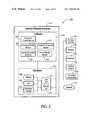
- FIG. 2illustrates an Image Acquisition System 200 according to one embodiment of the present invention suitable for mosaicing camera images.
- Image Acquisition System 200includes a General Purpose Computer 210 for performing image processing.
- the Hardware Components 202include a Processor (i.e., CPU) 206 , Memory 208 (ROM, RAM, etc.), Persistent Storage 210 (e.g., CD-ROM, hard drive, floppy drive, tape drive, etc.), User I/O 212 , and Network I/O 214 .
- a Processori.e., CPU
- Memory 208ROM, RAM, etc.
- Persistent Storage 210e.g., CD-ROM, hard drive, floppy drive, tape drive, etc.
- User I/O 212User I/O 212
- Network I/O 214Network I/O 214 .
- the User I/O 212can include a Keyboard 136 , a Pointing Device 138 (e.g., pointing stick, mouse, etc.), a Display 132 , a Camera System 137 representing one or more video cameras, and a Translation Mechanism 106 .
- the Network I/O 214is a communications gateway to a Network 215 such as, a LAN, WAN, or the Internet.
- the Software Modules 204 of General Purpose Computer 210includes an Operating System 216 and various Application programs such as a Frame Merger Module 218 , a Document Editing Module 220 , and an Image Enhancement Module 222 .
- the Operating System 216permits Processor 206 to control the various hardware devices such as Camera System 137 and Display 132 .
- a Frame Merger Module 218is adapted to stitch together multiple views of an image area of interest recorded by Camera System 137 for viewing on Display 132 . Subsequently, if desired, the composite image generated by Frame Merger Module 218 can be enhanced or edited by invoking an Image Enhancement Module 222 or a Document Editing Module 220 , respectively.
- Translation Mechanism 106is controlled by a Translation Control Module 224 . Alternatively, Translation Mechanism 106 may be controlled by hardware such as control circuitry (not shown).
- General Purpose Computer 210can be defined by any one of a plurality of configurations.
- Processor 206may in alternative embodiments, be defined by a collection of microprocessors configured for multiprocessing.
- the functions provided by Software Modules 204may be distributed across multiple computers acting together as a single processing unit.
- one or more aspects of the various Software Modules 204may be implemented in hardware, rather than software.
- the image processing by General Purpose Computer 210may be implemented in other data processing devices.
- mosaicing image with an offset lensmay be implemented in hardware and/or software in a portable device, such as a document camera (i.e., a camera system capable of performing image processing).
- FIGS. 3A , 3 B, 4 A and 4 Billustrate one embodiment of the present invention that is implemented with a video camera having an array sensor.
- FIGS. 3A and 3Billustrate the relative size and position of various views within an Area of Interest 300 visible to a camera.
- Each of the views 310 and 320represent a portion of Area of Interest 300 (also referred to as a tile or mosaic), which can be recorded within a frame.
- the Area of Interest 300may include various types of 2D objects such as a document page, a portion of a document page, or any other media including text and/or graphics, located on a desktop, whiteboards, or other surface and/or various types of 3D objects such as a human hand.
- FIG. 3Aillustrates a view (shown as view 1 ) of the upper left hand region of Area of Interest 300 and FIG. 3B illustrates a view (shown as view 2 ) of the lower right hand region of Area of Interest 300 .
- Area of Interest 300is much larger than an image recorded by the camera (also referred to as a “camera image”).
- a camera imagealso referred to as a “camera image”.
- several overlapping smaller views of the Area of Interest 300must be recorded by the camera. This can be accomplished by positioning the camera lens at a plurality of predetermined offset positions. At each predetermined offset position, the camera records an image of one of the views. The region of overlap between the smaller camera images allow them to be patched together to form a composite image in accordance with various known tiling, mosaicing, and/or stitching algorithms.
- the advantage of stitching together several smaller images to form a composite imageis that the resolution of Area of Interest 300 can be improved for more accurate document image decoding by OCR, improved legibility or improved quality of pictures on a page.
- a driving mechanism for translating the lensis optional.
- a multiple camera systemmay be used.
- each camerais positioned and configured to view a portion (e.g., quadrant) of the area of interest.
- the lensmay be offset from the image sensor in one or more of the cameras, the lens may not need to be translated because it remains at that fixed offset.
- FIG. 10which illustrates an example of a multiple camera system according to one embodiment of the present invention will be discussed in more detail below.
- FIGS. 4A and 4Billustrate a perspective view of a Video Camera 400 which illustrates how a translation mechanism (not shown) may position Lens 410 with respect to Array Sensor 420 to capture multiple views of Area of Interest 300 .
- the Lens 410is positioned at a first offset position in FIG. 4A and a second offset position in FIG. 4B .
- Array Sensor 420is an integral part of camera 400 whereas Lens 410 is detachable from Camera 400 .
- Lens 410is positionable within a plane, which is orthogonal to the optical axis of Lens 410 .
- Array Sensor 420 and Lens 410are also positioned in parallel planes formed by two axes, which are separated by a distance along the a third axis.
- Array Sensor 420is located in a first x-y plane and Lens 410 is located in a second x-y plane (also referred to as a lens plane) such that Lens 410 and Array Sensor 420 are separated by a distance D along the z-axis.
- Lens 410 and Array 420are separated by a distance of 20 mm.
- Array Sensor 420 and Lens 410may not be positioned in parallel planes.
- FIG. 4Aillustrates the position of Lens 410 within an x-y plane when capturing a view of the upper left region of Area of Interest 300 .
- FIG. 4Billustrates the position of Lens 410 within a x-y plane when capturing a view of the bottom right region of Area of Interest 300 .
- Arrows 450 and 460illustrate the direction in which Lens 410 may be shifted, which corresponds to movement along the x-axis and y-axis, respectively.
- a first view (e.g., view 310 ) of Area 300is recorded by positioning Lens 410 at a first position within a plane substantially orthogonal to an optical axis of Lens 410 .
- a second view (e.g., view 320 ) of Area 300is recorded by positioning Lens 410 at a second position within the plane substantially orthogonal to the optical axis of Lens 410 .
- a next view of Area 300is recorded by positioning Lens 410 at a next position within the plane substantially orthogonal to the optical axis of Lens 410 until all views are recorded. All recorded views are combined to produce a composite image of Area 300 , which has a higher resolution than the image of the individual views.
- a line-scan cameramay be used to capture an image of an object.
- a line-scan cameraincludes a linear sensor such as a line-scan CCD.
- Available linear sensorshave a high resolution in one dimension, but can be used to acquire a two-dimensional image if the lens is moved perpendicular to the linear sensor. Using exposures taken in succession, a two-dimensional image of the object is assembled.
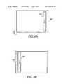
- FIGS. 6A and 6Billustrate various views captured by a linear sensor with respect to an Area of Interest 600 according to one embodiment of the present invention.
- FIG. 6Aillustrates a view (view 1 ) taken from the left side of Area of Interest 600 (while lens 710 is positioned at a first offset position) and
- FIG. 6Billustrates a view (view 2 ) taken from the right side of Area of Interest 600 (while lens 710 is positioned at a second offset position).
- FIGS. 7A and 7Billustrate perspective views of a line-scan camera system 700 according to one embodiment of the present invention positioned to record various views of an area of interest. More specifically, FIGS. 7A and 7B illustrate the positioning of Lens 710 with respect to Linear Sensor 720 to capture views 610 and 620 , respectively. Arrow 750 illustrates the direction in which Lens 710 is moved (i.e., along the y-axis), which is perpendicular to the Linear Sensor 720 . Continuous movement of Lens 710 is controlled by a single-axis translation mechanism such as mechanism 900 shown in FIG. 9 . For an alternative embodiment of the present invention, a dual axis translation mechanism may be used to move Lens 710 along two axes.
- a first view (e.g., view 610 ) of Area 600is recorded by positioning Lens 710 at a first position within a plane substantially orthogonal to an optical axis of Lens 710 .
- a second view (e.g., view 620 ) of Area 600is recorded by positioning Lens 710 at a second position within the plane substantially orthogonal to the optical axis of Lens 710 .
- a next view of Area 600is recorded by positioning Lens 710 at a next position within the plane substantially orthogonal to the optical axis of Lens 710 until all views are recorded. All recorded views are combined to produce a composite image of Area 600 , which has a higher resolution than the image of the individual views.
- FIGS. 4A and 4Billustrate the manner in which Array Sensor 420 is enclosed by a Housing 470 of a video camera and FIGS. 7A and 7B illustrate the manner in which Linear Sensor 720 is enclosed by a Housing 770 of a line-scan camera.
- the expandability of the light shieldallows the lens to be moved to any offset position within a given area so that camera images of varying degree of overlap can be obtained.
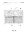
- a light shieldsuch as a bellow made of a expandable material, is attached between the camera housing and optics as shown in FIGS. 5A and 5B and FIGS. 8A and 8B .
- the light shieldprevents stray light from striking the image sensors such as Array Sensor 420 and Linear Sensor 720 .
- FIG. 5illustrates Array Sensor 420 , which is partially enclosed by housing 470 . Attached to the outer perimeter of Lens 410 is one end of a Bellows 510 . The other end of Bellows 510 is attached to Housing 470 exterior to Array Sensor 420 .
- FIG. 5illustrates the position of Lens 410 and Bellows 510 at a first position and indicates where an object point 520 is detected by Array Sensor 420 .
- FIG. 5also illustrates the position of Lens 420 and Bellows 510 at a second position and indicates where an object point 530 is detected by Array Sensor 420 . Note that object point 530 is located slightly to the left of object point 520 .
- Arrow 540indicates the direction in which Lens 410 moves within a plane parallel to Image Sensor 420 .
- FIG. 8illustrate Linear Sensor 720 , which is partially enclosed by housing 770 . Attached to the outer perimeter of Lens 710 is one end of a Bellows 810 . The other end of Bellows 810 is attached to Housing 770 exterior to Linear Sensor 720 .
- FIG. 8illustrates the position of Lens 710 and Bellows 810 at a first position and indicates where an object point 820 is detected by Linear Sensor 720 .
- FIG. 8illustrates the position of Lens 720 and Bellows 810 at a second position and indicates where an object point 830 is detected by Linear Sensor 720 . Note that object point 830 is located slightly to the left of object point 820 .
- Arrow 840indicates the direction in which Lens 710 moves within a plane parallel to Image Sensor 720 .
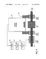
- Translation Mechanism 900 shown in FIG. 9illustrates one embodiment of a one-dimensional translation device used to move lens 910 along a single axis, such as the y-axis.
- Translation Mechanism 900includes a Motor 920 coupled to a Lead Screw 930 and Linear Bearings 940 . Linear Bearings 940 are used to constrain the motion of Lead Screw 930 along some line, such as the y-axis.
- Translation Mechanism 900also includes a Motor 920 coupled to a Motor Driver Circuit 960 .
- the Motor Driver Circuit 960is coupled to Computer 980 (such as General Purpose Computer 210 ) via Serial or Parallel Interface 970 .
- Computer 980receives output data from the camera housed in Camera Housing 950 .
- Translation Mechanism 900is able to move a 35 mm SLR lens along one axis using a linear actuator. The motion is controlled via a computer and allows positioning to less than 0.5 mm.
- a translation mechanism for two axescan be implemented by modifying Translation Mechanism 900 to translate in two directions.
- fixed lens shiftscan be achieved by mounting the lens on a wheel with its axis parallel to, but not shifted relative to an optical axis of the lens.
- several lensescan be mounted in a filter wheel type arrangement so that each lens has a slight predetermined offset.
- FIG. 10illustrates a cross-sectional view of a Multiple Camera System 1000 positioned to view an Image Area of Interest 1020 according to one embodiment of the present invention.
- Camera System 1000includes four Cameras 1001 , 1002 , 1003 , and 1004 for recording camera images.
- the camera images recorded by Cameras 1001 – 1004are combined by mosaicing to obtain a composite image having a higher resolution.
- multiple camerasmay be used to record multiple camera images simultaneously.
- Each of the Cameras 1001 – 1004 in Camera System 1000is positioned and configured to view a portion of Image Area of Interest 1020 , which is located on Surface 1010 .
- Cameras 1001 – 1004are housed together within a Housing 1040 , which is supported by a Mount 1030 attached to Surface 1010 .
- Housing 1040generally is attached to a desk-lamp like arm placed on the user's table or clamped to the side of the table, or fits under a bookshelf or is attached to a wall behind a desk.
- Camera 1001is positioned to view area 1021
- Camera 1002is positioned to view Area 1022
- Camera 1003is positioned to view Area 1023
- Camera 1004is positioned to view Area 1024 .
- Image Area of Interest 1020is a newspaper column
- each of the Cameras 1001 – 1004can capture regions of roughly a half-page size.
- Overlapping Regions 1050 , 1055 , and 1060represent portions of Areas 1021 – 1024 that overlap with an adjacent Area 1021 – 1024 .
- FIG. 10illustrates that the camera lens may be shifted or laterally displaced to view the appropriate region.
- the lensis shifted in a plane parallel to the plane of the image sensor.
- each of Lens 1011 – 1014is a pair of achromatic lenses for minimizing both chromatic and spherical aberrations. More specifically, Lens 1011 is shifted to the left and Lens 1014 is shifted to the right, while Lens 1012 and 1013 are not shifted.
- Cameras 1001 and 1004view Areas 1021 and 1024 , respectively, at oblique angles while Cameras 1002 and 1003 view Areas 1022 and 1023 , respectively, directly above their field of view.
- the various camera Lens 1011 – 1014are shifted by an offset.
- the offsetis dependent upon the distance the lens is above area to be viewed, the distance of the lens from the sensor and the focal lengths of the lens.
- one or more of the cameras in a multiple camera systemmay have fixed lens offsets.
- one or more of the cameras in the multiple camera systemmay have lens which may be shifted to a number of different offsets. If the lens can be shifted, then the lens will require a translation mechanism for shifting the lens and a movable light shield.
- a plurality of views(e.g., 1021 , 1022 , 1023 , and 1024 ) are recorded with a plurality of cameras (e.g., 1001 , 1002 , 1003 , and 1004 ).
- One or more of the camerashas an offset lens positioned within a plane substantially orthogonal to an optical axis of its lens. All recorded views are combined to produce a composite image of Area 1020 .
- the composite imagehas a resolution higher than the images of the individual views.
- FIGS. 11 and 12illustrate an alternative embodiment of a single Camera System 1100 .
- Lens 1120remains at a fixed offset while obtaining camera images for mosaicing. Rather than changing the lens offset, Camera 1120 is rotated (e.g., 180 degrees) as shown by Arrow 1140 .
- Camera 1101is supported by a Mount 1130 , which is attached to a Surface 1110 .
- the Image Area of Interest 1102is positioned on Surface 1110 .
- FIG. 11illustrates Camera 1101 configured to view an Area 1105 of Area of Interest 1102 .
- FIG. 12illustrates Camera 1101 configured to view an Area 1106 of Image Area of Interest 1102 .
- Camera 1101has been rotated approximately 180 degrees from its position shown in FIG. 11 .
- Areas 1105 and 1106is viewed by Camera 1101 at oblique angles.
- a first view(e.g., view 1105 ) is recorded while the lens is positioned at an offset position within a plane substantially orthogonal to an optical axis of the lens while the camera is at a first camera position.
- the Camera 1101is rotated (e.g., 180 degrees) to a second camera position.
- a second view(e.g., 1106 ) is recorded while the lens is positioned at the same offset position within the same plane at the second camera position.
- the Camera 1101is rotated again until all views are recorded. All recorded views are combined to produce a composite image of Area 1102 , which has a resolution higher than images of the views.
Landscapes
- Engineering & Computer Science (AREA)
- Multimedia (AREA)
- Signal Processing (AREA)
- Physics & Mathematics (AREA)
- General Physics & Mathematics (AREA)
- Studio Devices (AREA)
Abstract
Description
Claims (12)
Priority Applications (1)
| Application Number | Priority Date | Filing Date | Title |
|---|---|---|---|
| US09/408,873US7123292B1 (en) | 1999-09-29 | 1999-09-29 | Mosaicing images with an offset lens |
Applications Claiming Priority (1)
| Application Number | Priority Date | Filing Date | Title |
|---|---|---|---|
| US09/408,873US7123292B1 (en) | 1999-09-29 | 1999-09-29 | Mosaicing images with an offset lens |
Publications (1)
| Publication Number | Publication Date |
|---|---|
| US7123292B1true US7123292B1 (en) | 2006-10-17 |
Family
ID=37085947
Family Applications (1)
| Application Number | Title | Priority Date | Filing Date |
|---|---|---|---|
| US09/408,873Expired - Fee RelatedUS7123292B1 (en) | 1999-09-29 | 1999-09-29 | Mosaicing images with an offset lens |
Country Status (1)
| Country | Link |
|---|---|
| US (1) | US7123292B1 (en) |
Cited By (147)
| Publication number | Priority date | Publication date | Assignee | Title |
|---|---|---|---|---|
| US20020041282A1 (en)* | 2000-08-08 | 2002-04-11 | Ricoh Company, Ltd. | Shape measurement system |
| US20060023074A1 (en)* | 2004-07-28 | 2006-02-02 | Microsoft Corporation | Omni-directional camera with calibration and up look angle improvements |
| US20060268360A1 (en)* | 2005-05-12 | 2006-11-30 | Jones Peter W J | Methods of creating a virtual window |
| US20070132857A1 (en)* | 2005-12-12 | 2007-06-14 | Grip Stip M | Multi-mega pixel resolution with small sensor |
| US20070165129A1 (en)* | 2003-09-04 | 2007-07-19 | Lyndon Hill | Method of and apparatus for selecting a stereoscopic pair of images |
| US20070172229A1 (en)* | 2006-01-20 | 2007-07-26 | Sony Ericsson Mobile Communications Ab | Camera for electronic device |
| US20070230748A1 (en)* | 2006-03-30 | 2007-10-04 | Benjamin Perkins Foss | System for capturing and presenting text while maintaining material context during optical character recognition |
| US20070230786A1 (en)* | 2006-03-30 | 2007-10-04 | Benjamin Perkins Foss | System for capturing and presenting text using video image capture for optical character recognition |
| US20070280534A1 (en)* | 2006-06-05 | 2007-12-06 | Benjamin Perkins Foss | Method for capturing and presenting test using video image capture for optical character recognition |
| US20070285554A1 (en)* | 2005-10-31 | 2007-12-13 | Dor Givon | Apparatus method and system for imaging |
| US20070291281A1 (en)* | 2006-06-15 | 2007-12-20 | Konica Minolta Sensing, Inc. | Three-dimensional shape measuring system |
| US20080260210A1 (en)* | 2007-04-23 | 2008-10-23 | Lea Kobeli | Text capture and presentation device |
| USRE40628E1 (en)* | 1999-11-15 | 2009-01-27 | Shih-Huang Chen | Apparatus for reducing exposing time of an image processing system |
| US20090128636A1 (en)* | 2007-11-19 | 2009-05-21 | Sony Corporation | Image pickup apparatus |
| US20090172513A1 (en)* | 2007-12-31 | 2009-07-02 | Gretchen Anderson | Reading device with shortcut read function |
| US20090169061A1 (en)* | 2007-12-27 | 2009-07-02 | Gretchen Anderson | Reading device with hierarchal navigation |
| US20090309853A1 (en)* | 2008-06-13 | 2009-12-17 | Polyvision Corporation | Electronic whiteboard system and assembly with optical detection elements |
| US20100295868A1 (en)* | 2009-05-20 | 2010-11-25 | Dacuda Ag | Image processing for handheld scanner |
| US20100296129A1 (en)* | 2009-05-20 | 2010-11-25 | Dacuda Ag | Automatic sizing of images acquired by a handheld scanner |
| US20100296140A1 (en)* | 2009-05-20 | 2010-11-25 | Dacuda Ag | Handheld scanner with high image quality |
| US20110069148A1 (en)* | 2009-09-22 | 2011-03-24 | Tenebraex Corporation | Systems and methods for correcting images in a multi-sensor system |
| US20110069180A1 (en)* | 2009-09-23 | 2011-03-24 | Microsoft Corporation | Camera-based scanning |
| US20110129124A1 (en)* | 2004-07-30 | 2011-06-02 | Dor Givon | Method circuit and system for human to machine interfacing by hand gestures |
| US20110163948A1 (en)* | 2008-09-04 | 2011-07-07 | Dor Givon | Method system and software for providing image sensor based human machine interfacing |
| US20110228115A1 (en)* | 2010-03-16 | 2011-09-22 | Microsoft Corporation | Large Format Digital Camera |
| US20110234497A1 (en)* | 2010-03-25 | 2011-09-29 | Dacuda Ag | Computer peripheral for scanning |
| US20110234807A1 (en)* | 2007-11-16 | 2011-09-29 | Tenebraex Corporation | Digital security camera |
| US20110234815A1 (en)* | 2010-03-25 | 2011-09-29 | Dacuda Ag | Synchronization of navigation and image information for handheld scanner |
| US20120044328A1 (en)* | 2010-08-17 | 2012-02-23 | Apple Inc. | Image capture using luminance and chrominance sensors |
| US8350946B2 (en) | 2005-01-31 | 2013-01-08 | The Invention Science Fund I, Llc | Viewfinder for shared image device |
| US8441696B2 (en) | 2009-05-20 | 2013-05-14 | Dacuda Ag | Continuous scanning with a handheld scanner |
| US8498100B1 (en) | 2012-03-02 | 2013-07-30 | Microsoft Corporation | Flexible hinge and removable attachment |
| US8538132B2 (en) | 2010-09-24 | 2013-09-17 | Apple Inc. | Component concentricity |
| US8548258B2 (en) | 2008-10-24 | 2013-10-01 | Extreme Reality Ltd. | Method system and associated modules and software components for providing image sensor based human machine interfacing |
| US8606383B2 (en) | 2005-01-31 | 2013-12-10 | The Invention Science Fund I, Llc | Audio sharing |
| US8610726B2 (en) | 2008-09-26 | 2013-12-17 | Apple Inc. | Computer systems and methods with projected display |
| US20130335789A1 (en)* | 2012-06-13 | 2013-12-19 | Pfu Limited | Overhead image reading apparatus |
| US8654030B1 (en) | 2012-10-16 | 2014-02-18 | Microsoft Corporation | Antenna placement |
| US8681100B2 (en) | 2004-07-30 | 2014-03-25 | Extreme Realty Ltd. | Apparatus system and method for human-machine-interface |
| US8699819B1 (en)* | 2012-05-10 | 2014-04-15 | Google Inc. | Mosaicing documents for translation using video streams |
| US8719603B2 (en) | 2012-03-02 | 2014-05-06 | Microsoft Corporation | Accessory device authentication |
| US8730372B2 (en) | 2011-09-23 | 2014-05-20 | Apple Inc. | Partially lit sensor |
| US8733423B1 (en) | 2012-10-17 | 2014-05-27 | Microsoft Corporation | Metal alloy injection molding protrusions |
| US8749529B2 (en) | 2012-03-01 | 2014-06-10 | Microsoft Corporation | Sensor-in-pixel display system with near infrared filter |
| US8761596B2 (en) | 2008-09-26 | 2014-06-24 | Apple Inc. | Dichroic aperture for electronic imaging device |
| US8786767B2 (en) | 2012-11-02 | 2014-07-22 | Microsoft Corporation | Rapid synchronized lighting and shuttering |
| US8873227B2 (en) | 2012-03-02 | 2014-10-28 | Microsoft Corporation | Flexible hinge support layer |
| US8878779B2 (en) | 2009-09-21 | 2014-11-04 | Extreme Reality Ltd. | Methods circuits device systems and associated computer executable code for facilitating interfacing with a computing platform display screen |
| US8902320B2 (en)* | 2005-01-31 | 2014-12-02 | The Invention Science Fund I, Llc | Shared image device synchronization or designation |
| US8928654B2 (en) | 2004-07-30 | 2015-01-06 | Extreme Reality Ltd. | Methods, systems, devices and associated processing logic for generating stereoscopic images and video |
| US8947353B2 (en) | 2012-06-12 | 2015-02-03 | Microsoft Corporation | Photosensor array gesture detection |
| US8949477B2 (en) | 2012-05-14 | 2015-02-03 | Microsoft Technology Licensing, Llc | Accessory device architecture |
| US8952892B2 (en) | 2012-11-01 | 2015-02-10 | Microsoft Corporation | Input location correction tables for input panels |
| US8964379B2 (en) | 2012-08-20 | 2015-02-24 | Microsoft Corporation | Switchable magnetic lock |
| US20150092072A1 (en)* | 2013-09-29 | 2015-04-02 | Lenovo (Beijing) Co., Ltd. | Data Acquiring Method And Electronic Device Thereof |
| US9001215B2 (en) | 2005-06-02 | 2015-04-07 | The Invention Science Fund I, Llc | Estimating shared image device operational capabilities or resources |
| US9019615B2 (en) | 2012-06-12 | 2015-04-28 | Microsoft Technology Licensing, Llc | Wide field-of-view virtual image projector |
| US9027631B2 (en) | 2012-10-17 | 2015-05-12 | Microsoft Technology Licensing, Llc | Metal alloy injection molding overflows |
| US9046962B2 (en) | 2005-10-31 | 2015-06-02 | Extreme Reality Ltd. | Methods, systems, apparatuses, circuits and associated computer executable code for detecting motion, position and/or orientation of objects within a defined spatial region |
| US9052414B2 (en) | 2012-02-07 | 2015-06-09 | Microsoft Technology Licensing, Llc | Virtual image device |
| US9064654B2 (en) | 2012-03-02 | 2015-06-23 | Microsoft Technology Licensing, Llc | Method of manufacturing an input device |
| US9075566B2 (en) | 2012-03-02 | 2015-07-07 | Microsoft Technoogy Licensing, LLC | Flexible hinge spine |
| US9073123B2 (en) | 2012-06-13 | 2015-07-07 | Microsoft Technology Licensing, Llc | Housing vents |
| US9082456B2 (en) | 2005-01-31 | 2015-07-14 | The Invention Science Fund I Llc | Shared image device designation |
| US9094540B2 (en) | 2012-12-13 | 2015-07-28 | Microsoft Technology Licensing, Llc | Displacing image on imager in multi-lens cameras |
| US9124729B2 (en) | 2005-01-31 | 2015-09-01 | The Invention Science Fund I, Llc | Shared image device synchronization or designation |
| US9152173B2 (en) | 2012-10-09 | 2015-10-06 | Microsoft Technology Licensing, Llc | Transparent display device |
| US20150296177A1 (en)* | 2012-11-26 | 2015-10-15 | Intouch Technologies, Inc. | Enhanced video interaction for a user interface of a telepresence network |
| US20150302246A1 (en)* | 2014-04-22 | 2015-10-22 | Lenovo (Singapore) Pte. Ltd. | Forming scanned composite document with optical character recognition function |
| US9176538B2 (en) | 2013-02-05 | 2015-11-03 | Microsoft Technology Licensing, Llc | Input device configurations |
| US9177220B2 (en) | 2004-07-30 | 2015-11-03 | Extreme Reality Ltd. | System and method for 3D space-dimension based image processing |
| US9201185B2 (en) | 2011-02-04 | 2015-12-01 | Microsoft Technology Licensing, Llc | Directional backlighting for display panels |
| US9218126B2 (en) | 2009-09-21 | 2015-12-22 | Extreme Reality Ltd. | Methods circuits apparatus and systems for human machine interfacing with an electronic appliance |
| US9256089B2 (en) | 2012-06-15 | 2016-02-09 | Microsoft Technology Licensing, Llc | Object-detecting backlight unit |
| US9307133B1 (en) | 2015-02-11 | 2016-04-05 | Pho Imaging Limited | System and method of imaging for increasing image resolution |
| US9304549B2 (en) | 2013-03-28 | 2016-04-05 | Microsoft Technology Licensing, Llc | Hinge mechanism for rotatable component attachment |
| US9317072B2 (en) | 2014-01-28 | 2016-04-19 | Microsoft Technology Licensing, Llc | Hinge mechanism with preset positions |
| US20160112645A1 (en)* | 2013-05-03 | 2016-04-21 | Kofax, Inc. | Systems and methods for improving video captured using mobile devices |
| US9354748B2 (en) | 2012-02-13 | 2016-05-31 | Microsoft Technology Licensing, Llc | Optical stylus interaction |
| US9355345B2 (en) | 2012-07-23 | 2016-05-31 | Microsoft Technology Licensing, Llc | Transparent tags with encoded data |
| US9356061B2 (en) | 2013-08-05 | 2016-05-31 | Apple Inc. | Image sensor with buried light shield and vertical gate |
| US9360893B2 (en) | 2012-03-02 | 2016-06-07 | Microsoft Technology Licensing, Llc | Input device writing surface |
| US9426905B2 (en) | 2012-03-02 | 2016-08-23 | Microsoft Technology Licensing, Llc | Connection device for computing devices |
| CN105928494A (en)* | 2016-07-04 | 2016-09-07 | 成都电科创品机器人科技有限公司 | Stereoscopic vision scanning and positioning device, scanning method and positioning method |
| US9448631B2 (en) | 2013-12-31 | 2016-09-20 | Microsoft Technology Licensing, Llc | Input device haptics and pressure sensing |
| US9447620B2 (en) | 2014-09-30 | 2016-09-20 | Microsoft Technology Licensing, Llc | Hinge mechanism with multiple preset positions |
| US9459160B2 (en) | 2012-06-13 | 2016-10-04 | Microsoft Technology Licensing, Llc | Input device sensor configuration |
| US9489717B2 (en) | 2005-01-31 | 2016-11-08 | Invention Science Fund I, Llc | Shared image device |
| US9513748B2 (en) | 2012-12-13 | 2016-12-06 | Microsoft Technology Licensing, Llc | Combined display panel circuit |
| US9525222B2 (en) | 2014-04-11 | 2016-12-20 | Apple Inc. | Reducing or eliminating board-to-board connectors |
| US9552777B2 (en) | 2013-05-10 | 2017-01-24 | Microsoft Technology Licensing, Llc | Phase control backlight |
| US9638835B2 (en) | 2013-03-05 | 2017-05-02 | Microsoft Technology Licensing, Llc | Asymmetric aberration correcting lens |
| US9661770B2 (en) | 2012-10-17 | 2017-05-23 | Microsoft Technology Licensing, Llc | Graphic formation via material ablation |
| US9666967B2 (en) | 2014-07-28 | 2017-05-30 | Apple Inc. | Printed circuit board connector for non-planar configurations |
| US9684382B2 (en) | 2012-06-13 | 2017-06-20 | Microsoft Technology Licensing, Llc | Input device configuration having capacitive and pressure sensors |
| US9706089B2 (en) | 2012-03-02 | 2017-07-11 | Microsoft Technology Licensing, Llc | Shifted lens camera for mobile computing devices |
| US9747499B2 (en)* | 2015-03-03 | 2017-08-29 | Fuji Xerox Co., Ltd. | Systems and methods for detection and high-quality capture of documents on a cluttered tabletop with an automatically controlled camera |
| US9747504B2 (en) | 2013-11-15 | 2017-08-29 | Kofax, Inc. | Systems and methods for generating composite images of long documents using mobile video data |
| US9752361B2 (en) | 2015-06-18 | 2017-09-05 | Microsoft Technology Licensing, Llc | Multistage hinge |
| US9760788B2 (en) | 2014-10-30 | 2017-09-12 | Kofax, Inc. | Mobile document detection and orientation based on reference object characteristics |
| US9759854B2 (en) | 2014-02-17 | 2017-09-12 | Microsoft Technology Licensing, Llc | Input device outer layer and backlighting |
| US20170262159A1 (en)* | 2016-03-11 | 2017-09-14 | Fuji Xerox Co., Ltd. | Capturing documents from screens for archival, search, annotation, and sharing |
| US9767379B2 (en) | 2009-02-10 | 2017-09-19 | Kofax, Inc. | Systems, methods and computer program products for determining document validity |
| US9767354B2 (en) | 2009-02-10 | 2017-09-19 | Kofax, Inc. | Global geographic information retrieval, validation, and normalization |
| US9769354B2 (en) | 2005-03-24 | 2017-09-19 | Kofax, Inc. | Systems and methods of processing scanned data |
| US9779296B1 (en) | 2016-04-01 | 2017-10-03 | Kofax, Inc. | Content-based detection and three dimensional geometric reconstruction of objects in image and video data |
| US9785149B2 (en) | 2011-01-28 | 2017-10-10 | Intouch Technologies, Inc. | Time-dependent navigation of telepresence robots |
| US9819490B2 (en) | 2005-05-04 | 2017-11-14 | Invention Science Fund I, Llc | Regional proximity for shared image device(s) |
| US9864415B2 (en) | 2015-06-30 | 2018-01-09 | Microsoft Technology Licensing, Llc | Multistage friction hinge |
| US9870066B2 (en) | 2012-03-02 | 2018-01-16 | Microsoft Technology Licensing, Llc | Method of manufacturing an input device |
| US9910341B2 (en) | 2005-01-31 | 2018-03-06 | The Invention Science Fund I, Llc | Shared image device designation |
| US9946954B2 (en) | 2013-09-27 | 2018-04-17 | Kofax, Inc. | Determining distance between an object and a capture device based on captured image data |
| US9996741B2 (en) | 2013-03-13 | 2018-06-12 | Kofax, Inc. | Systems and methods for classifying objects in digital images captured using mobile devices |
| US10003762B2 (en) | 2005-04-26 | 2018-06-19 | Invention Science Fund I, Llc | Shared image devices |
| US10031556B2 (en) | 2012-06-08 | 2018-07-24 | Microsoft Technology Licensing, Llc | User experience adaptation |
| US10037057B2 (en) | 2016-09-22 | 2018-07-31 | Microsoft Technology Licensing, Llc | Friction hinge |
| US10051724B1 (en) | 2014-01-31 | 2018-08-14 | Apple Inc. | Structural ground reference for an electronic component of a computing device |
| US10061896B2 (en) | 2012-05-22 | 2018-08-28 | Intouch Technologies, Inc. | Graphical user interfaces including touchpad driving interfaces for telemedicine devices |
| US10061385B2 (en) | 2016-01-22 | 2018-08-28 | Microsoft Technology Licensing, Llc | Haptic feedback for a touch input device |
| US10120420B2 (en) | 2014-03-21 | 2018-11-06 | Microsoft Technology Licensing, Llc | Lockable display and techniques enabling use of lockable displays |
| CN108833746A (en)* | 2018-05-29 | 2018-11-16 | Oppo(重庆)智能科技有限公司 | Camera components and electronic equipment |
| US10142568B2 (en)* | 2017-02-13 | 2018-11-27 | Semiconductor Components Industries, Llc | Methods and apparatus for vignette and out-of-focus correction |
| US10142522B2 (en) | 2013-12-03 | 2018-11-27 | Ml Netherlands C.V. | User feedback for real-time checking and improving quality of scanned image |
| US10146803B2 (en) | 2013-04-23 | 2018-12-04 | Kofax, Inc | Smart mobile application development platform |
| US10146795B2 (en) | 2012-01-12 | 2018-12-04 | Kofax, Inc. | Systems and methods for mobile image capture and processing |
| US10156889B2 (en) | 2014-09-15 | 2018-12-18 | Microsoft Technology Licensing, Llc | Inductive peripheral retention device |
| US10222889B2 (en) | 2015-06-03 | 2019-03-05 | Microsoft Technology Licensing, Llc | Force inputs and cursor control |
| US10242285B2 (en) | 2015-07-20 | 2019-03-26 | Kofax, Inc. | Iterative recognition-guided thresholding and data extraction |
| US10298898B2 (en) | 2013-08-31 | 2019-05-21 | Ml Netherlands C.V. | User feedback for real-time checking and improving quality of scanned image |
| US10310370B2 (en) | 2016-12-29 | 2019-06-04 | Vivotek Inc. | Image capturing device with high image sensing coverage rate and related image capturing method |
| US10317575B2 (en) | 2016-05-04 | 2019-06-11 | Global Weather Corporation | Method and apparatus for forecasting weather |
| US10324733B2 (en) | 2014-07-30 | 2019-06-18 | Microsoft Technology Licensing, Llc | Shutdown notifications |
| US10328576B2 (en) | 2012-05-22 | 2019-06-25 | Intouch Technologies, Inc. | Social behavior rules for a medical telepresence robot |
| US10344797B2 (en) | 2016-04-05 | 2019-07-09 | Microsoft Technology Licensing, Llc | Hinge with multiple preset positions |
| US10410321B2 (en) | 2014-01-07 | 2019-09-10 | MN Netherlands C.V. | Dynamic updating of a composite image |
| US10416799B2 (en) | 2015-06-03 | 2019-09-17 | Microsoft Technology Licensing, Llc | Force sensing and inadvertent input control of an input device |
| US10467465B2 (en) | 2015-07-20 | 2019-11-05 | Kofax, Inc. | Range and/or polarity-based thresholding for improved data extraction |
| US10484561B2 (en) | 2014-05-12 | 2019-11-19 | Ml Netherlands C.V. | Method and apparatus for scanning and printing a 3D object |
| US10578499B2 (en) | 2013-02-17 | 2020-03-03 | Microsoft Technology Licensing, Llc | Piezo-actuated virtual buttons for touch surfaces |
| US10657600B2 (en) | 2012-01-12 | 2020-05-19 | Kofax, Inc. | Systems and methods for mobile image capture and processing |
| US10708491B2 (en) | 2014-01-07 | 2020-07-07 | Ml Netherlands C.V. | Adaptive camera control for reducing motion blur during real-time image capture |
| US10803350B2 (en) | 2017-11-30 | 2020-10-13 | Kofax, Inc. | Object detection and image cropping using a multi-detector approach |
| US10945664B1 (en) | 2015-09-30 | 2021-03-16 | Apple, Inc. | Protective case with coupling gasket for a wearable electronic device |
| EP3731731A4 (en)* | 2017-12-28 | 2021-09-22 | Broadspot Imaging Corporation | OPTICAL IMAGING DEVICE WITH MULTIPLE EXTERNAL CHANNELS AND ROTATING DEVICE |
| USRE48963E1 (en) | 2012-03-02 | 2022-03-08 | Microsoft Technology Licensing, Llc | Connection device for computing devices |
| WO2023225105A1 (en)* | 2022-05-17 | 2023-11-23 | EyeQ Technologies, Inc. | Three-dimensional ocular endoscope device and methods of use |
| US12100181B2 (en) | 2020-05-11 | 2024-09-24 | Magic Leap, Inc. | Computationally efficient method for computing a composite representation of a 3D environment |
Citations (22)
| Publication number | Priority date | Publication date | Assignee | Title |
|---|---|---|---|---|
| US4751570A (en)* | 1984-12-07 | 1988-06-14 | Max Robinson | Generation of apparently three-dimensional images |
| US5339188A (en)* | 1992-09-16 | 1994-08-16 | Hughes Aircraft Company | Step stare scanning apparatus and method |
| US5453784A (en)* | 1993-02-10 | 1995-09-26 | Krishnan; Arun | Imaging apparatus and method for determining range and determining focus information |
| US5511148A (en) | 1993-04-30 | 1996-04-23 | Xerox Corporation | Interactive copying system |
| US5528290A (en)* | 1994-09-09 | 1996-06-18 | Xerox Corporation | Device for transcribing images on a board using a camera based board scanner |
| US5557327A (en)* | 1994-02-23 | 1996-09-17 | Konica Corporation | Image input apparatus with two-dimensional pixel shift |
| US5561460A (en)* | 1993-06-02 | 1996-10-01 | Hamamatsu Photonics K.K. | Solid-state image pick up device having a rotating plate for shifting position of the image on a sensor array |
| US5656078A (en)* | 1995-11-14 | 1997-08-12 | Memc Electronic Materials, Inc. | Non-distorting video camera for use with a system for controlling growth of a silicon crystal |
| US5686960A (en)* | 1992-01-14 | 1997-11-11 | Michael Sussman | Image input device having optical deflection elements for capturing multiple sub-images |
| US5705806A (en) | 1994-03-14 | 1998-01-06 | Minolta Co., Ltd. | Image reading apparatus |
| US5774179A (en)* | 1994-12-28 | 1998-06-30 | Minister Of National Defence | Method and system for fast microscanning |
| US5978143A (en)* | 1997-09-19 | 1999-11-02 | Carl-Zeiss-Stiftung | Stereoscopic recording and display system |
| US6005682A (en) | 1995-06-07 | 1999-12-21 | Xerox Corporation | Resolution enhancement by multiple scanning with a low-resolution, two-dimensional sensor array |
| US6067112A (en)* | 1996-07-12 | 2000-05-23 | Xerox Corporation | Interactive desktop display system for automatically adjusting pan and zoom functions in response to user adjustment of a feedback image |
| US6072529A (en)* | 1996-09-16 | 2000-06-06 | Eastman Kodak Company | Electronic camera for the realization of the imaging properties of a studio bellow camera |
| US6104840A (en)* | 1996-11-08 | 2000-08-15 | Ricoh Company, Ltd. | Method and system for generating a composite image from partially overlapping adjacent images taken along a plurality of axes |
| US6137535A (en)* | 1996-11-04 | 2000-10-24 | Eastman Kodak Company | Compact digital camera with segmented fields of view |
| US6256058B1 (en)* | 1996-06-06 | 2001-07-03 | Compaq Computer Corporation | Method for simultaneously compositing a panoramic image and determining camera focal length |
| US6493469B1 (en)* | 1999-06-28 | 2002-12-10 | Xerox Corporation | Dual video camera system for scanning hardcopy documents |
| US6583811B2 (en)* | 1996-10-25 | 2003-06-24 | Fuji Photo Film Co., Ltd. | Photographic system for recording data and reproducing images using correlation data between frames |
| US6657667B1 (en)* | 1997-11-25 | 2003-12-02 | Flashpoint Technology, Inc. | Method and apparatus for capturing a multidimensional array of overlapping images for composite image generation |
| US6686956B1 (en)* | 1999-08-31 | 2004-02-03 | International Business Machines Corporation | Increased resolution digital capture device |
- 1999
- 1999-09-29USUS09/408,873patent/US7123292B1/ennot_activeExpired - Fee Related
Patent Citations (22)
| Publication number | Priority date | Publication date | Assignee | Title |
|---|---|---|---|---|
| US4751570A (en)* | 1984-12-07 | 1988-06-14 | Max Robinson | Generation of apparently three-dimensional images |
| US5686960A (en)* | 1992-01-14 | 1997-11-11 | Michael Sussman | Image input device having optical deflection elements for capturing multiple sub-images |
| US5339188A (en)* | 1992-09-16 | 1994-08-16 | Hughes Aircraft Company | Step stare scanning apparatus and method |
| US5453784A (en)* | 1993-02-10 | 1995-09-26 | Krishnan; Arun | Imaging apparatus and method for determining range and determining focus information |
| US5511148A (en) | 1993-04-30 | 1996-04-23 | Xerox Corporation | Interactive copying system |
| US5561460A (en)* | 1993-06-02 | 1996-10-01 | Hamamatsu Photonics K.K. | Solid-state image pick up device having a rotating plate for shifting position of the image on a sensor array |
| US5557327A (en)* | 1994-02-23 | 1996-09-17 | Konica Corporation | Image input apparatus with two-dimensional pixel shift |
| US5705806A (en) | 1994-03-14 | 1998-01-06 | Minolta Co., Ltd. | Image reading apparatus |
| US5528290A (en)* | 1994-09-09 | 1996-06-18 | Xerox Corporation | Device for transcribing images on a board using a camera based board scanner |
| US5774179A (en)* | 1994-12-28 | 1998-06-30 | Minister Of National Defence | Method and system for fast microscanning |
| US6005682A (en) | 1995-06-07 | 1999-12-21 | Xerox Corporation | Resolution enhancement by multiple scanning with a low-resolution, two-dimensional sensor array |
| US5656078A (en)* | 1995-11-14 | 1997-08-12 | Memc Electronic Materials, Inc. | Non-distorting video camera for use with a system for controlling growth of a silicon crystal |
| US6256058B1 (en)* | 1996-06-06 | 2001-07-03 | Compaq Computer Corporation | Method for simultaneously compositing a panoramic image and determining camera focal length |
| US6067112A (en)* | 1996-07-12 | 2000-05-23 | Xerox Corporation | Interactive desktop display system for automatically adjusting pan and zoom functions in response to user adjustment of a feedback image |
| US6072529A (en)* | 1996-09-16 | 2000-06-06 | Eastman Kodak Company | Electronic camera for the realization of the imaging properties of a studio bellow camera |
| US6583811B2 (en)* | 1996-10-25 | 2003-06-24 | Fuji Photo Film Co., Ltd. | Photographic system for recording data and reproducing images using correlation data between frames |
| US6137535A (en)* | 1996-11-04 | 2000-10-24 | Eastman Kodak Company | Compact digital camera with segmented fields of view |
| US6104840A (en)* | 1996-11-08 | 2000-08-15 | Ricoh Company, Ltd. | Method and system for generating a composite image from partially overlapping adjacent images taken along a plurality of axes |
| US5978143A (en)* | 1997-09-19 | 1999-11-02 | Carl-Zeiss-Stiftung | Stereoscopic recording and display system |
| US6657667B1 (en)* | 1997-11-25 | 2003-12-02 | Flashpoint Technology, Inc. | Method and apparatus for capturing a multidimensional array of overlapping images for composite image generation |
| US6493469B1 (en)* | 1999-06-28 | 2002-12-10 | Xerox Corporation | Dual video camera system for scanning hardcopy documents |
| US6686956B1 (en)* | 1999-08-31 | 2004-02-03 | International Business Machines Corporation | Increased resolution digital capture device |
Non-Patent Citations (4)
| Title |
|---|
| Canon Camera Lens Product Description published on Internet @ http://www.usa.canon.com/camcambin/cameras/lenses.html. |
| Canon EF Mount Block diagram of TS-E24mm F3.5L published on Internet @ http://www.canon.co.jp/camera-museum/lens/ef/ts<SUB>-</SUB>e24<SUB>-</SUB>35k.html. |
| Canon EF Mount TS-E 24mm f/3.5L published on Internet @ http://www.canon.co.jp/camera-museum/lens/ef/ts<SUB>-</SUB>e24<SUB>-</SUB>35.html. |
| Zappala, T., Gee, A., and Taylor, M., "Document mosaicing," Proceedings of British Machine Vision Conference, BMVC-97, Essex, England, Sep. 1997, Ed. A. F. Clark, pp. 600-609. |
Cited By (274)
| Publication number | Priority date | Publication date | Assignee | Title |
|---|---|---|---|---|
| USRE40628E1 (en)* | 1999-11-15 | 2009-01-27 | Shih-Huang Chen | Apparatus for reducing exposing time of an image processing system |
| US20020041282A1 (en)* | 2000-08-08 | 2002-04-11 | Ricoh Company, Ltd. | Shape measurement system |
| US7310154B2 (en)* | 2000-08-08 | 2007-12-18 | Ricoh Company, Ltd. | Shape measurement system |
| US20070165129A1 (en)* | 2003-09-04 | 2007-07-19 | Lyndon Hill | Method of and apparatus for selecting a stereoscopic pair of images |
| US8026950B2 (en)* | 2003-09-04 | 2011-09-27 | Sharp Kabushiki Kaisha | Method of and apparatus for selecting a stereoscopic pair of images |
| US20060023074A1 (en)* | 2004-07-28 | 2006-02-02 | Microsoft Corporation | Omni-directional camera with calibration and up look angle improvements |
| US7495694B2 (en)* | 2004-07-28 | 2009-02-24 | Microsoft Corp. | Omni-directional camera with calibration and up look angle improvements |
| US8681100B2 (en) | 2004-07-30 | 2014-03-25 | Extreme Realty Ltd. | Apparatus system and method for human-machine-interface |
| US9177220B2 (en) | 2004-07-30 | 2015-11-03 | Extreme Reality Ltd. | System and method for 3D space-dimension based image processing |
| US20110129124A1 (en)* | 2004-07-30 | 2011-06-02 | Dor Givon | Method circuit and system for human to machine interfacing by hand gestures |
| US8872899B2 (en) | 2004-07-30 | 2014-10-28 | Extreme Reality Ltd. | Method circuit and system for human to machine interfacing by hand gestures |
| US8928654B2 (en) | 2004-07-30 | 2015-01-06 | Extreme Reality Ltd. | Methods, systems, devices and associated processing logic for generating stereoscopic images and video |
| US8350946B2 (en) | 2005-01-31 | 2013-01-08 | The Invention Science Fund I, Llc | Viewfinder for shared image device |
| US8902320B2 (en)* | 2005-01-31 | 2014-12-02 | The Invention Science Fund I, Llc | Shared image device synchronization or designation |
| US8606383B2 (en) | 2005-01-31 | 2013-12-10 | The Invention Science Fund I, Llc | Audio sharing |
| US9910341B2 (en) | 2005-01-31 | 2018-03-06 | The Invention Science Fund I, Llc | Shared image device designation |
| US9489717B2 (en) | 2005-01-31 | 2016-11-08 | Invention Science Fund I, Llc | Shared image device |
| US9124729B2 (en) | 2005-01-31 | 2015-09-01 | The Invention Science Fund I, Llc | Shared image device synchronization or designation |
| US9082456B2 (en) | 2005-01-31 | 2015-07-14 | The Invention Science Fund I Llc | Shared image device designation |
| US9769354B2 (en) | 2005-03-24 | 2017-09-19 | Kofax, Inc. | Systems and methods of processing scanned data |
| US10003762B2 (en) | 2005-04-26 | 2018-06-19 | Invention Science Fund I, Llc | Shared image devices |
| US9819490B2 (en) | 2005-05-04 | 2017-11-14 | Invention Science Fund I, Llc | Regional proximity for shared image device(s) |
| US20060268360A1 (en)* | 2005-05-12 | 2006-11-30 | Jones Peter W J | Methods of creating a virtual window |
| US9001215B2 (en) | 2005-06-02 | 2015-04-07 | The Invention Science Fund I, Llc | Estimating shared image device operational capabilities or resources |
| US9131220B2 (en) | 2005-10-31 | 2015-09-08 | Extreme Reality Ltd. | Apparatus method and system for imaging |
| US9046962B2 (en) | 2005-10-31 | 2015-06-02 | Extreme Reality Ltd. | Methods, systems, apparatuses, circuits and associated computer executable code for detecting motion, position and/or orientation of objects within a defined spatial region |
| US8878896B2 (en) | 2005-10-31 | 2014-11-04 | Extreme Reality Ltd. | Apparatus method and system for imaging |
| US20110080496A1 (en)* | 2005-10-31 | 2011-04-07 | Dor Givon | Apparatus Method and System for Imaging |
| US8462199B2 (en) | 2005-10-31 | 2013-06-11 | Extreme Reality Ltd. | Apparatus method and system for imaging |
| US20100194862A1 (en)* | 2005-10-31 | 2010-08-05 | Xtrextreme Reality | Apparatus Method and System for Imaging |
| US20070285554A1 (en)* | 2005-10-31 | 2007-12-13 | Dor Givon | Apparatus method and system for imaging |
| US20070132857A1 (en)* | 2005-12-12 | 2007-06-14 | Grip Stip M | Multi-mega pixel resolution with small sensor |
| US8072502B2 (en)* | 2005-12-12 | 2011-12-06 | Sony Ericsson Mobile Communications Ab | Multi-mega pixel resolution with small sensor |
| US20070172229A1 (en)* | 2006-01-20 | 2007-07-26 | Sony Ericsson Mobile Communications Ab | Camera for electronic device |
| US7822338B2 (en)* | 2006-01-20 | 2010-10-26 | Sony Ericsson Mobile Communications Ab | Camera for electronic device |
| US20070230786A1 (en)* | 2006-03-30 | 2007-10-04 | Benjamin Perkins Foss | System for capturing and presenting text using video image capture for optical character recognition |
| US8208729B2 (en)* | 2006-03-30 | 2012-06-26 | Loquitur, Inc. | Capturing and presenting text using video image capture for optical character recognition |
| US7792363B2 (en)* | 2006-03-30 | 2010-09-07 | Benjamin Perkins Foss | Use of level detection while capturing and presenting text with optical character recognition |
| US20070230748A1 (en)* | 2006-03-30 | 2007-10-04 | Benjamin Perkins Foss | System for capturing and presenting text while maintaining material context during optical character recognition |
| US20070280534A1 (en)* | 2006-06-05 | 2007-12-06 | Benjamin Perkins Foss | Method for capturing and presenting test using video image capture for optical character recognition |
| US20070291281A1 (en)* | 2006-06-15 | 2007-12-20 | Konica Minolta Sensing, Inc. | Three-dimensional shape measuring system |
| US7715020B2 (en)* | 2006-06-15 | 2010-05-11 | Konica Minolta Sensing, Inc. | Three-dimensional shape measuring system |
| US20080260210A1 (en)* | 2007-04-23 | 2008-10-23 | Lea Kobeli | Text capture and presentation device |
| US8594387B2 (en)* | 2007-04-23 | 2013-11-26 | Intel-Ge Care Innovations Llc | Text capture and presentation device |
| US8791984B2 (en) | 2007-11-16 | 2014-07-29 | Scallop Imaging, Llc | Digital security camera |
| US20110234807A1 (en)* | 2007-11-16 | 2011-09-29 | Tenebraex Corporation | Digital security camera |
| US8068138B2 (en)* | 2007-11-19 | 2011-11-29 | Sony Corporation | Image pickup apparatus for reducing fixed pattern noise |
| US20090128636A1 (en)* | 2007-11-19 | 2009-05-21 | Sony Corporation | Image pickup apparatus |
| US8233671B2 (en) | 2007-12-27 | 2012-07-31 | Intel-Ge Care Innovations Llc | Reading device with hierarchal navigation |
| US20090169061A1 (en)* | 2007-12-27 | 2009-07-02 | Gretchen Anderson | Reading device with hierarchal navigation |
| US8185398B2 (en) | 2007-12-31 | 2012-05-22 | Intel-Ge Care Innovations Llc | Reading device with shortcut read function |
| US8452601B2 (en) | 2007-12-31 | 2013-05-28 | Intel-Ge Care Innovations Llc | Reading device with shortcut read function |
| US20090172513A1 (en)* | 2007-12-31 | 2009-07-02 | Gretchen Anderson | Reading device with shortcut read function |
| US20090309853A1 (en)* | 2008-06-13 | 2009-12-17 | Polyvision Corporation | Electronic whiteboard system and assembly with optical detection elements |
| US20110163948A1 (en)* | 2008-09-04 | 2011-07-07 | Dor Givon | Method system and software for providing image sensor based human machine interfacing |
| US8761596B2 (en) | 2008-09-26 | 2014-06-24 | Apple Inc. | Dichroic aperture for electronic imaging device |
| US8610726B2 (en) | 2008-09-26 | 2013-12-17 | Apple Inc. | Computer systems and methods with projected display |
| US8548258B2 (en) | 2008-10-24 | 2013-10-01 | Extreme Reality Ltd. | Method system and associated modules and software components for providing image sensor based human machine interfacing |
| US9767354B2 (en) | 2009-02-10 | 2017-09-19 | Kofax, Inc. | Global geographic information retrieval, validation, and normalization |
| US9767379B2 (en) | 2009-02-10 | 2017-09-19 | Kofax, Inc. | Systems, methods and computer program products for determining document validity |
| US20100296129A1 (en)* | 2009-05-20 | 2010-11-25 | Dacuda Ag | Automatic sizing of images acquired by a handheld scanner |
| US8441695B2 (en) | 2009-05-20 | 2013-05-14 | Dacuda Ag | Handheld scanner with high image quality |
| US10225428B2 (en) | 2009-05-20 | 2019-03-05 | Ml Netherlands C.V. | Image processing for handheld scanner |
| US20100295868A1 (en)* | 2009-05-20 | 2010-11-25 | Dacuda Ag | Image processing for handheld scanner |
| US20100296140A1 (en)* | 2009-05-20 | 2010-11-25 | Dacuda Ag | Handheld scanner with high image quality |
| US20100296131A1 (en)* | 2009-05-20 | 2010-11-25 | Dacuda Ag | Real-time display of images acquired by a handheld scanner |
| US8441696B2 (en) | 2009-05-20 | 2013-05-14 | Dacuda Ag | Continuous scanning with a handheld scanner |
| US8723885B2 (en) | 2009-05-20 | 2014-05-13 | Dacuda Ag | Real-time display of images acquired by a handheld scanner |
| US9300834B2 (en) | 2009-05-20 | 2016-03-29 | Dacuda Ag | Image processing for handheld scanner |
| US8582182B2 (en) | 2009-05-20 | 2013-11-12 | Dacuda Ag | Automatic sizing of images acquired by a handheld scanner |
| US8878779B2 (en) | 2009-09-21 | 2014-11-04 | Extreme Reality Ltd. | Methods circuits device systems and associated computer executable code for facilitating interfacing with a computing platform display screen |
| US9218126B2 (en) | 2009-09-21 | 2015-12-22 | Extreme Reality Ltd. | Methods circuits apparatus and systems for human machine interfacing with an electronic appliance |
| WO2011037964A1 (en)* | 2009-09-22 | 2011-03-31 | Tenebraex Corporation | Systems and methods for correcting images in a multi-sensor system |
| US20110069148A1 (en)* | 2009-09-22 | 2011-03-24 | Tenebraex Corporation | Systems and methods for correcting images in a multi-sensor system |
| US8704896B2 (en) | 2009-09-23 | 2014-04-22 | Microsoft Corporation | Camera-based scanning |
| US20110069180A1 (en)* | 2009-09-23 | 2011-03-24 | Microsoft Corporation | Camera-based scanning |
| US8345106B2 (en) | 2009-09-23 | 2013-01-01 | Microsoft Corporation | Camera-based scanning |
| US20110228115A1 (en)* | 2010-03-16 | 2011-09-22 | Microsoft Corporation | Large Format Digital Camera |
| US20110234815A1 (en)* | 2010-03-25 | 2011-09-29 | Dacuda Ag | Synchronization of navigation and image information for handheld scanner |
| US8497840B2 (en) | 2010-03-25 | 2013-07-30 | Dacuda Ag | Computer peripheral for scanning |
| US8339467B2 (en) | 2010-03-25 | 2012-12-25 | Dacuda Ag | Synchronization of navigation and image information for handheld scanner |
| US20110234497A1 (en)* | 2010-03-25 | 2011-09-29 | Dacuda Ag | Computer peripheral for scanning |
| US8497897B2 (en)* | 2010-08-17 | 2013-07-30 | Apple Inc. | Image capture using luminance and chrominance sensors |
| US20120044328A1 (en)* | 2010-08-17 | 2012-02-23 | Apple Inc. | Image capture using luminance and chrominance sensors |
| US8538132B2 (en) | 2010-09-24 | 2013-09-17 | Apple Inc. | Component concentricity |
| US10591921B2 (en) | 2011-01-28 | 2020-03-17 | Intouch Technologies, Inc. | Time-dependent navigation of telepresence robots |
| US11468983B2 (en) | 2011-01-28 | 2022-10-11 | Teladoc Health, Inc. | Time-dependent navigation of telepresence robots |
| US9785149B2 (en) | 2011-01-28 | 2017-10-10 | Intouch Technologies, Inc. | Time-dependent navigation of telepresence robots |
| US9201185B2 (en) | 2011-02-04 | 2015-12-01 | Microsoft Technology Licensing, Llc | Directional backlighting for display panels |
| US8730372B2 (en) | 2011-09-23 | 2014-05-20 | Apple Inc. | Partially lit sensor |
| US10664919B2 (en) | 2012-01-12 | 2020-05-26 | Kofax, Inc. | Systems and methods for mobile image capture and processing |
| US10657600B2 (en) | 2012-01-12 | 2020-05-19 | Kofax, Inc. | Systems and methods for mobile image capture and processing |
| US10146795B2 (en) | 2012-01-12 | 2018-12-04 | Kofax, Inc. | Systems and methods for mobile image capture and processing |
| US9052414B2 (en) | 2012-02-07 | 2015-06-09 | Microsoft Technology Licensing, Llc | Virtual image device |
| US9354748B2 (en) | 2012-02-13 | 2016-05-31 | Microsoft Technology Licensing, Llc | Optical stylus interaction |
| US8749529B2 (en) | 2012-03-01 | 2014-06-10 | Microsoft Corporation | Sensor-in-pixel display system with near infrared filter |
| US8646999B2 (en) | 2012-03-02 | 2014-02-11 | Microsoft Corporation | Pressure sensitive key normalization |
| US8719603B2 (en) | 2012-03-02 | 2014-05-06 | Microsoft Corporation | Accessory device authentication |
| US8498100B1 (en) | 2012-03-02 | 2013-07-30 | Microsoft Corporation | Flexible hinge and removable attachment |
| US8947864B2 (en) | 2012-03-02 | 2015-02-03 | Microsoft Corporation | Flexible hinge and removable attachment |
| USRE48963E1 (en) | 2012-03-02 | 2022-03-08 | Microsoft Technology Licensing, Llc | Connection device for computing devices |
| US10963087B2 (en) | 2012-03-02 | 2021-03-30 | Microsoft Technology Licensing, Llc | Pressure sensitive keys |
| US8543227B1 (en) | 2012-03-02 | 2013-09-24 | Microsoft Corporation | Sensor fusion algorithm |
| US8548608B2 (en) | 2012-03-02 | 2013-10-01 | Microsoft Corporation | Sensor fusion algorithm |
| US8564944B2 (en) | 2012-03-02 | 2013-10-22 | Microsoft Corporation | Flux fountain |
| US8903517B2 (en) | 2012-03-02 | 2014-12-02 | Microsoft Corporation | Computer device and an apparatus having sensors configured for measuring spatial information indicative of a position of the computing devices |
| US8570725B2 (en) | 2012-03-02 | 2013-10-29 | Microsoft Corporation | Flexible hinge and removable attachment |
| US8610015B2 (en) | 2012-03-02 | 2013-12-17 | Microsoft Corporation | Input device securing techniques |
| US10013030B2 (en) | 2012-03-02 | 2018-07-03 | Microsoft Technology Licensing, Llc | Multiple position input device cover |
| US9047207B2 (en) | 2012-03-02 | 2015-06-02 | Microsoft Technology Licensing, Llc | Mobile device power state |
| US9946307B2 (en) | 2012-03-02 | 2018-04-17 | Microsoft Technology Licensing, Llc | Classifying the intent of user input |
| US8896993B2 (en) | 2012-03-02 | 2014-11-25 | Microsoft Corporation | Input device layers and nesting |
| US9064654B2 (en) | 2012-03-02 | 2015-06-23 | Microsoft Technology Licensing, Llc | Method of manufacturing an input device |
| US9075566B2 (en) | 2012-03-02 | 2015-07-07 | Microsoft Technoogy Licensing, LLC | Flexible hinge spine |
| US8614666B2 (en) | 2012-03-02 | 2013-12-24 | Microsoft Corporation | Sensing user input at display area edge |
| US8873227B2 (en) | 2012-03-02 | 2014-10-28 | Microsoft Corporation | Flexible hinge support layer |
| US9904327B2 (en) | 2012-03-02 | 2018-02-27 | Microsoft Technology Licensing, Llc | Flexible hinge and removable attachment |
| US9870066B2 (en) | 2012-03-02 | 2018-01-16 | Microsoft Technology Licensing, Llc | Method of manufacturing an input device |
| US9098117B2 (en) | 2012-03-02 | 2015-08-04 | Microsoft Technology Licensing, Llc | Classifying the intent of user input |
| US9111703B2 (en) | 2012-03-02 | 2015-08-18 | Microsoft Technology Licensing, Llc | Sensor stack venting |
| US9116550B2 (en) | 2012-03-02 | 2015-08-25 | Microsoft Technology Licensing, Llc | Device kickstand |
| US8854799B2 (en) | 2012-03-02 | 2014-10-07 | Microsoft Corporation | Flux fountain |
| US8850241B2 (en) | 2012-03-02 | 2014-09-30 | Microsoft Corporation | Multi-stage power adapter configured to provide low power upon initial connection of the power adapter to the host device and high power thereafter upon notification from the host device to the power adapter |
| US9134808B2 (en) | 2012-03-02 | 2015-09-15 | Microsoft Technology Licensing, Llc | Device kickstand |
| US9134807B2 (en) | 2012-03-02 | 2015-09-15 | Microsoft Technology Licensing, Llc | Pressure sensitive key normalization |
| US9146620B2 (en) | 2012-03-02 | 2015-09-29 | Microsoft Technology Licensing, Llc | Input device assembly |
| US9852855B2 (en) | 2012-03-02 | 2017-12-26 | Microsoft Technology Licensing, Llc | Pressure sensitive key normalization |
| US9158384B2 (en) | 2012-03-02 | 2015-10-13 | Microsoft Technology Licensing, Llc | Flexible hinge protrusion attachment |
| US9158383B2 (en) | 2012-03-02 | 2015-10-13 | Microsoft Technology Licensing, Llc | Force concentrator |
| US9793073B2 (en) | 2012-03-02 | 2017-10-17 | Microsoft Technology Licensing, Llc | Backlighting a fabric enclosure of a flexible cover |
| US8699215B2 (en) | 2012-03-02 | 2014-04-15 | Microsoft Corporation | Flexible hinge spine |
| US9766663B2 (en) | 2012-03-02 | 2017-09-19 | Microsoft Technology Licensing, Llc | Hinge for component attachment |
| US9176901B2 (en) | 2012-03-02 | 2015-11-03 | Microsoft Technology Licensing, Llc | Flux fountain |
| US9176900B2 (en) | 2012-03-02 | 2015-11-03 | Microsoft Technology Licensing, Llc | Flexible hinge and removable attachment |
| US8830668B2 (en) | 2012-03-02 | 2014-09-09 | Microsoft Corporation | Flexible hinge and removable attachment |
| US8791382B2 (en) | 2012-03-02 | 2014-07-29 | Microsoft Corporation | Input device securing techniques |
| US8935774B2 (en) | 2012-03-02 | 2015-01-13 | Microsoft Corporation | Accessory device authentication |
| US8724302B2 (en) | 2012-03-02 | 2014-05-13 | Microsoft Corporation | Flexible hinge support layer |
| US9268373B2 (en) | 2012-03-02 | 2016-02-23 | Microsoft Technology Licensing, Llc | Flexible hinge spine |
| US9275809B2 (en) | 2012-03-02 | 2016-03-01 | Microsoft Technology Licensing, Llc | Device camera angle |
| US8780540B2 (en) | 2012-03-02 | 2014-07-15 | Microsoft Corporation | Flexible hinge and removable attachment |
| US9298236B2 (en) | 2012-03-02 | 2016-03-29 | Microsoft Technology Licensing, Llc | Multi-stage power adapter configured to provide a first power level upon initial connection of the power adapter to the host device and a second power level thereafter upon notification from the host device to the power adapter |
| US9304948B2 (en) | 2012-03-02 | 2016-04-05 | Microsoft Technology Licensing, Llc | Sensing user input at display area edge |
| US9710093B2 (en) | 2012-03-02 | 2017-07-18 | Microsoft Technology Licensing, Llc | Pressure sensitive key normalization |
| US9706089B2 (en) | 2012-03-02 | 2017-07-11 | Microsoft Technology Licensing, Llc | Shifted lens camera for mobile computing devices |
| US9304949B2 (en) | 2012-03-02 | 2016-04-05 | Microsoft Technology Licensing, Llc | Sensing user input at display area edge |
| US9678542B2 (en) | 2012-03-02 | 2017-06-13 | Microsoft Technology Licensing, Llc | Multiple position input device cover |
| US9619071B2 (en) | 2012-03-02 | 2017-04-11 | Microsoft Technology Licensing, Llc | Computing device and an apparatus having sensors configured for measuring spatial information indicative of a position of the computing devices |
| US9618977B2 (en) | 2012-03-02 | 2017-04-11 | Microsoft Technology Licensing, Llc | Input device securing techniques |
| US9465412B2 (en) | 2012-03-02 | 2016-10-11 | Microsoft Technology Licensing, Llc | Input device layers and nesting |
| US8780541B2 (en) | 2012-03-02 | 2014-07-15 | Microsoft Corporation | Flexible hinge and removable attachment |
| US9460029B2 (en) | 2012-03-02 | 2016-10-04 | Microsoft Technology Licensing, Llc | Pressure sensitive keys |
| US9426905B2 (en) | 2012-03-02 | 2016-08-23 | Microsoft Technology Licensing, Llc | Connection device for computing devices |
| US9360893B2 (en) | 2012-03-02 | 2016-06-07 | Microsoft Technology Licensing, Llc | Input device writing surface |
| US9411751B2 (en) | 2012-03-02 | 2016-08-09 | Microsoft Technology Licensing, Llc | Key formation |
| US8897598B1 (en) | 2012-05-10 | 2014-11-25 | Google Inc. | Mosaicing documents for translation using video streams |
| US8699819B1 (en)* | 2012-05-10 | 2014-04-15 | Google Inc. | Mosaicing documents for translation using video streams |
| US9959241B2 (en) | 2012-05-14 | 2018-05-01 | Microsoft Technology Licensing, Llc | System and method for accessory device architecture that passes via intermediate processor a descriptor when processing in a low power state |
| US9348605B2 (en) | 2012-05-14 | 2016-05-24 | Microsoft Technology Licensing, Llc | System and method for accessory device architecture that passes human interface device (HID) data via intermediate processor |
| US8949477B2 (en) | 2012-05-14 | 2015-02-03 | Microsoft Technology Licensing, Llc | Accessory device architecture |
| US9098304B2 (en) | 2012-05-14 | 2015-08-04 | Microsoft Technology Licensing, Llc | Device enumeration support method for computing devices that does not natively support device enumeration |
| US10328576B2 (en) | 2012-05-22 | 2019-06-25 | Intouch Technologies, Inc. | Social behavior rules for a medical telepresence robot |
| US10892052B2 (en) | 2012-05-22 | 2021-01-12 | Intouch Technologies, Inc. | Graphical user interfaces including touchpad driving interfaces for telemedicine devices |
| US11453126B2 (en) | 2012-05-22 | 2022-09-27 | Teladoc Health, Inc. | Clinical workflows utilizing autonomous and semi-autonomous telemedicine devices |
| US10061896B2 (en) | 2012-05-22 | 2018-08-28 | Intouch Technologies, Inc. | Graphical user interfaces including touchpad driving interfaces for telemedicine devices |
| US11628571B2 (en) | 2012-05-22 | 2023-04-18 | Teladoc Health, Inc. | Social behavior rules for a medical telepresence robot |
| US10780582B2 (en) | 2012-05-22 | 2020-09-22 | Intouch Technologies, Inc. | Social behavior rules for a medical telepresence robot |
| US11515049B2 (en) | 2012-05-22 | 2022-11-29 | Teladoc Health, Inc. | Graphical user interfaces including touchpad driving interfaces for telemedicine devices |
| US10658083B2 (en) | 2012-05-22 | 2020-05-19 | Intouch Technologies, Inc. | Graphical user interfaces including touchpad driving interfaces for telemedicine devices |
| US10031556B2 (en) | 2012-06-08 | 2018-07-24 | Microsoft Technology Licensing, Llc | User experience adaptation |
| US9019615B2 (en) | 2012-06-12 | 2015-04-28 | Microsoft Technology Licensing, Llc | Wide field-of-view virtual image projector |
| US10107994B2 (en) | 2012-06-12 | 2018-10-23 | Microsoft Technology Licensing, Llc | Wide field-of-view virtual image projector |
| US8947353B2 (en) | 2012-06-12 | 2015-02-03 | Microsoft Corporation | Photosensor array gesture detection |
| US9350893B2 (en)* | 2012-06-13 | 2016-05-24 | Pfu Limited | Overhead image reading apparatus |
| US9952106B2 (en) | 2012-06-13 | 2018-04-24 | Microsoft Technology Licensing, Llc | Input device sensor configuration |
| US9073123B2 (en) | 2012-06-13 | 2015-07-07 | Microsoft Technology Licensing, Llc | Housing vents |
| US10228770B2 (en) | 2012-06-13 | 2019-03-12 | Microsoft Technology Licensing, Llc | Input device configuration having capacitive and pressure sensors |
| US9459160B2 (en) | 2012-06-13 | 2016-10-04 | Microsoft Technology Licensing, Llc | Input device sensor configuration |
| US9684382B2 (en) | 2012-06-13 | 2017-06-20 | Microsoft Technology Licensing, Llc | Input device configuration having capacitive and pressure sensors |
| US20130335789A1 (en)* | 2012-06-13 | 2013-12-19 | Pfu Limited | Overhead image reading apparatus |
| US9256089B2 (en) | 2012-06-15 | 2016-02-09 | Microsoft Technology Licensing, Llc | Object-detecting backlight unit |
| US9355345B2 (en) | 2012-07-23 | 2016-05-31 | Microsoft Technology Licensing, Llc | Transparent tags with encoded data |
| US9824808B2 (en) | 2012-08-20 | 2017-11-21 | Microsoft Technology Licensing, Llc | Switchable magnetic lock |
| US8964379B2 (en) | 2012-08-20 | 2015-02-24 | Microsoft Corporation | Switchable magnetic lock |
| US9152173B2 (en) | 2012-10-09 | 2015-10-06 | Microsoft Technology Licensing, Llc | Transparent display device |
| US8654030B1 (en) | 2012-10-16 | 2014-02-18 | Microsoft Corporation | Antenna placement |
| US9432070B2 (en) | 2012-10-16 | 2016-08-30 | Microsoft Technology Licensing, Llc | Antenna placement |
| US9661770B2 (en) | 2012-10-17 | 2017-05-23 | Microsoft Technology Licensing, Llc | Graphic formation via material ablation |
| US8991473B2 (en) | 2012-10-17 | 2015-03-31 | Microsoft Technology Holding, LLC | Metal alloy injection molding protrusions |
| US8733423B1 (en) | 2012-10-17 | 2014-05-27 | Microsoft Corporation | Metal alloy injection molding protrusions |
| US9027631B2 (en) | 2012-10-17 | 2015-05-12 | Microsoft Technology Licensing, Llc | Metal alloy injection molding overflows |
| US8952892B2 (en) | 2012-11-01 | 2015-02-10 | Microsoft Corporation | Input location correction tables for input panels |
| US9544504B2 (en) | 2012-11-02 | 2017-01-10 | Microsoft Technology Licensing, Llc | Rapid synchronized lighting and shuttering |
| US8786767B2 (en) | 2012-11-02 | 2014-07-22 | Microsoft Corporation | Rapid synchronized lighting and shuttering |
| US9571789B2 (en)* | 2012-11-26 | 2017-02-14 | Intouch Technologies, Inc. | Enhanced video interaction for a user interface of a telepresence network |
| US20150296177A1 (en)* | 2012-11-26 | 2015-10-15 | Intouch Technologies, Inc. | Enhanced video interaction for a user interface of a telepresence network |
| US10334205B2 (en) | 2012-11-26 | 2019-06-25 | Intouch Technologies, Inc. | Enhanced video interaction for a user interface of a telepresence network |
| US10924708B2 (en) | 2012-11-26 | 2021-02-16 | Teladoc Health, Inc. | Enhanced video interaction for a user interface of a telepresence network |
| US11910128B2 (en) | 2012-11-26 | 2024-02-20 | Teladoc Health, Inc. | Enhanced video interaction for a user interface of a telepresence network |
| US9513748B2 (en) | 2012-12-13 | 2016-12-06 | Microsoft Technology Licensing, Llc | Combined display panel circuit |
| US9094540B2 (en) | 2012-12-13 | 2015-07-28 | Microsoft Technology Licensing, Llc | Displacing image on imager in multi-lens cameras |
| US9176538B2 (en) | 2013-02-05 | 2015-11-03 | Microsoft Technology Licensing, Llc | Input device configurations |
| US10578499B2 (en) | 2013-02-17 | 2020-03-03 | Microsoft Technology Licensing, Llc | Piezo-actuated virtual buttons for touch surfaces |
| US9638835B2 (en) | 2013-03-05 | 2017-05-02 | Microsoft Technology Licensing, Llc | Asymmetric aberration correcting lens |
| US10127441B2 (en) | 2013-03-13 | 2018-11-13 | Kofax, Inc. | Systems and methods for classifying objects in digital images captured using mobile devices |
| US9996741B2 (en) | 2013-03-13 | 2018-06-12 | Kofax, Inc. | Systems and methods for classifying objects in digital images captured using mobile devices |
| US9304549B2 (en) | 2013-03-28 | 2016-04-05 | Microsoft Technology Licensing, Llc | Hinge mechanism for rotatable component attachment |
| US10146803B2 (en) | 2013-04-23 | 2018-12-04 | Kofax, Inc | Smart mobile application development platform |
| US9584729B2 (en)* | 2013-05-03 | 2017-02-28 | Kofax, Inc. | Systems and methods for improving video captured using mobile devices |
| US20160112645A1 (en)* | 2013-05-03 | 2016-04-21 | Kofax, Inc. | Systems and methods for improving video captured using mobile devices |
| US9552777B2 (en) | 2013-05-10 | 2017-01-24 | Microsoft Technology Licensing, Llc | Phase control backlight |
| US9356061B2 (en) | 2013-08-05 | 2016-05-31 | Apple Inc. | Image sensor with buried light shield and vertical gate |
| US9842875B2 (en) | 2013-08-05 | 2017-12-12 | Apple Inc. | Image sensor with buried light shield and vertical gate |
| US11563926B2 (en) | 2013-08-31 | 2023-01-24 | Magic Leap, Inc. | User feedback for real-time checking and improving quality of scanned image |
| US10298898B2 (en) | 2013-08-31 | 2019-05-21 | Ml Netherlands C.V. | User feedback for real-time checking and improving quality of scanned image |
| US10841551B2 (en) | 2013-08-31 | 2020-11-17 | Ml Netherlands C.V. | User feedback for real-time checking and improving quality of scanned image |
| US9946954B2 (en) | 2013-09-27 | 2018-04-17 | Kofax, Inc. | Determining distance between an object and a capture device based on captured image data |
| US9832377B2 (en)* | 2013-09-29 | 2017-11-28 | Lenovo (Beijing) Co., Ltd. | Data acquiring method and electronic device thereof |
| CN104519241A (en)* | 2013-09-29 | 2015-04-15 | 联想(北京)有限公司 | Data acquisition method and electronic equipment |
| US20150092072A1 (en)* | 2013-09-29 | 2015-04-02 | Lenovo (Beijing) Co., Ltd. | Data Acquiring Method And Electronic Device Thereof |
| US9747504B2 (en) | 2013-11-15 | 2017-08-29 | Kofax, Inc. | Systems and methods for generating composite images of long documents using mobile video data |
| US11798130B2 (en) | 2013-12-03 | 2023-10-24 | Magic Leap, Inc. | User feedback for real-time checking and improving quality of scanned image |
| US10142522B2 (en) | 2013-12-03 | 2018-11-27 | Ml Netherlands C.V. | User feedback for real-time checking and improving quality of scanned image |
| US11115565B2 (en) | 2013-12-03 | 2021-09-07 | Ml Netherlands C.V. | User feedback for real-time checking and improving quality of scanned image |
| US10455128B2 (en) | 2013-12-03 | 2019-10-22 | Ml Netherlands C.V. | User feedback for real-time checking and improving quality of scanned image |
| US10375279B2 (en) | 2013-12-03 | 2019-08-06 | Ml Netherlands C.V. | User feedback for real-time checking and improving quality of scanned image |
| US9448631B2 (en) | 2013-12-31 | 2016-09-20 | Microsoft Technology Licensing, Llc | Input device haptics and pressure sensing |
| US10359848B2 (en) | 2013-12-31 | 2019-07-23 | Microsoft Technology Licensing, Llc | Input device haptics and pressure sensing |
| US11315217B2 (en) | 2014-01-07 | 2022-04-26 | Ml Netherlands C.V. | Dynamic updating of a composite image |
| US10708491B2 (en) | 2014-01-07 | 2020-07-07 | Ml Netherlands C.V. | Adaptive camera control for reducing motion blur during real-time image capture |
| US10410321B2 (en) | 2014-01-07 | 2019-09-10 | MN Netherlands C.V. | Dynamic updating of a composite image |
| US11516383B2 (en) | 2014-01-07 | 2022-11-29 | Magic Leap, Inc. | Adaptive camera control for reducing motion blur during real-time image capture |
| US9317072B2 (en) | 2014-01-28 | 2016-04-19 | Microsoft Technology Licensing, Llc | Hinge mechanism with preset positions |
| US10051724B1 (en) | 2014-01-31 | 2018-08-14 | Apple Inc. | Structural ground reference for an electronic component of a computing device |
| US9759854B2 (en) | 2014-02-17 | 2017-09-12 | Microsoft Technology Licensing, Llc | Input device outer layer and backlighting |
| US10120420B2 (en) | 2014-03-21 | 2018-11-06 | Microsoft Technology Licensing, Llc | Lockable display and techniques enabling use of lockable displays |
| US9525222B2 (en) | 2014-04-11 | 2016-12-20 | Apple Inc. | Reducing or eliminating board-to-board connectors |
| US20150302246A1 (en)* | 2014-04-22 | 2015-10-22 | Lenovo (Singapore) Pte. Ltd. | Forming scanned composite document with optical character recognition function |
| US9881223B2 (en)* | 2014-04-22 | 2018-01-30 | Lenovo (Singapore) Pte. Ltd. | Forming scanned composite document with optical character recognition function |
| US10484561B2 (en) | 2014-05-12 | 2019-11-19 | Ml Netherlands C.V. | Method and apparatus for scanning and printing a 3D object |
| US11245806B2 (en) | 2014-05-12 | 2022-02-08 | Ml Netherlands C.V. | Method and apparatus for scanning and printing a 3D object |
| US12309333B2 (en) | 2014-05-12 | 2025-05-20 | Magic Leap, Inc. | Method and apparatus for scanning and printing a 3D object |
| US9666967B2 (en) | 2014-07-28 | 2017-05-30 | Apple Inc. | Printed circuit board connector for non-planar configurations |
| US10324733B2 (en) | 2014-07-30 | 2019-06-18 | Microsoft Technology Licensing, Llc | Shutdown notifications |
| US10156889B2 (en) | 2014-09-15 | 2018-12-18 | Microsoft Technology Licensing, Llc | Inductive peripheral retention device |
| US9964998B2 (en) | 2014-09-30 | 2018-05-08 | Microsoft Technology Licensing, Llc | Hinge mechanism with multiple preset positions |
| US9447620B2 (en) | 2014-09-30 | 2016-09-20 | Microsoft Technology Licensing, Llc | Hinge mechanism with multiple preset positions |
| US9760788B2 (en) | 2014-10-30 | 2017-09-12 | Kofax, Inc. | Mobile document detection and orientation based on reference object characteristics |
| US9307133B1 (en) | 2015-02-11 | 2016-04-05 | Pho Imaging Limited | System and method of imaging for increasing image resolution |
| US9747499B2 (en)* | 2015-03-03 | 2017-08-29 | Fuji Xerox Co., Ltd. | Systems and methods for detection and high-quality capture of documents on a cluttered tabletop with an automatically controlled camera |
| US10222889B2 (en) | 2015-06-03 | 2019-03-05 | Microsoft Technology Licensing, Llc | Force inputs and cursor control |
| US10416799B2 (en) | 2015-06-03 | 2019-09-17 | Microsoft Technology Licensing, Llc | Force sensing and inadvertent input control of an input device |
| US9752361B2 (en) | 2015-06-18 | 2017-09-05 | Microsoft Technology Licensing, Llc | Multistage hinge |
| US10606322B2 (en) | 2015-06-30 | 2020-03-31 | Microsoft Technology Licensing, Llc | Multistage friction hinge |
| US9864415B2 (en) | 2015-06-30 | 2018-01-09 | Microsoft Technology Licensing, Llc | Multistage friction hinge |
| US10242285B2 (en) | 2015-07-20 | 2019-03-26 | Kofax, Inc. | Iterative recognition-guided thresholding and data extraction |
| US10467465B2 (en) | 2015-07-20 | 2019-11-05 | Kofax, Inc. | Range and/or polarity-based thresholding for improved data extraction |
| US10945664B1 (en) | 2015-09-30 | 2021-03-16 | Apple, Inc. | Protective case with coupling gasket for a wearable electronic device |
| US10061385B2 (en) | 2016-01-22 | 2018-08-28 | Microsoft Technology Licensing, Llc | Haptic feedback for a touch input device |
| US10809895B2 (en)* | 2016-03-11 | 2020-10-20 | Fuji Xerox Co., Ltd. | Capturing documents from screens for archival, search, annotation, and sharing |
| US20170262159A1 (en)* | 2016-03-11 | 2017-09-14 | Fuji Xerox Co., Ltd. | Capturing documents from screens for archival, search, annotation, and sharing |
| US9779296B1 (en) | 2016-04-01 | 2017-10-03 | Kofax, Inc. | Content-based detection and three dimensional geometric reconstruction of objects in image and video data |
| US10344797B2 (en) | 2016-04-05 | 2019-07-09 | Microsoft Technology Licensing, Llc | Hinge with multiple preset positions |
| US10317575B2 (en) | 2016-05-04 | 2019-06-11 | Global Weather Corporation | Method and apparatus for forecasting weather |
| CN105928494A (en)* | 2016-07-04 | 2016-09-07 | 成都电科创品机器人科技有限公司 | Stereoscopic vision scanning and positioning device, scanning method and positioning method |
| US10037057B2 (en) | 2016-09-22 | 2018-07-31 | Microsoft Technology Licensing, Llc | Friction hinge |
| US10310370B2 (en) | 2016-12-29 | 2019-06-04 | Vivotek Inc. | Image capturing device with high image sensing coverage rate and related image capturing method |
| US10142568B2 (en)* | 2017-02-13 | 2018-11-27 | Semiconductor Components Industries, Llc | Methods and apparatus for vignette and out-of-focus correction |
| US10803350B2 (en) | 2017-11-30 | 2020-10-13 | Kofax, Inc. | Object detection and image cropping using a multi-detector approach |
| US11062176B2 (en) | 2017-11-30 | 2021-07-13 | Kofax, Inc. | Object detection and image cropping using a multi-detector approach |
| EP3731731A4 (en)* | 2017-12-28 | 2021-09-22 | Broadspot Imaging Corporation | OPTICAL IMAGING DEVICE WITH MULTIPLE EXTERNAL CHANNELS AND ROTATING DEVICE |
| CN108833746A (en)* | 2018-05-29 | 2018-11-16 | Oppo(重庆)智能科技有限公司 | Camera components and electronic equipment |
| US12100181B2 (en) | 2020-05-11 | 2024-09-24 | Magic Leap, Inc. | Computationally efficient method for computing a composite representation of a 3D environment |
| WO2023225105A1 (en)* | 2022-05-17 | 2023-11-23 | EyeQ Technologies, Inc. | Three-dimensional ocular endoscope device and methods of use |
Similar Documents
| Publication | Publication Date | Title |
|---|---|---|
| US7123292B1 (en) | Mosaicing images with an offset lens | |
| US6512539B1 (en) | Document periscope | |
| US6567126B1 (en) | Planar focus correction | |
| EP0974811B1 (en) | Digital cameras | |
| CN102906763A (en) | Document Imaging System with Capture Scanner and PC-based Processing Software | |
| JP4297630B2 (en) | Electronic imaging device | |
| US7072081B2 (en) | Compact portable 2D/ 3D image capture system | |
| WO2005010495A3 (en) | System and method for generating digital images of a microscope slide | |
| US5227896A (en) | Image reader for producing and synthesizing segmented image data | |
| CN1183873A (en) | Image scanning device and method | |
| JP2002111979A (en) | Method of scanning picture using look-down type linear array scanner and system thereof | |
| US6345129B1 (en) | Wide-field scanning tv | |
| US5909521A (en) | Multi-shot still image reader | |
| JPH10136237A (en) | Image pickup device | |
| JP3109580B2 (en) | IMAGE INPUT DEVICE AND COMPUTER-READABLE RECORDING MEDIUM RECORDING IMAGE PROCESSING PROGRAM FOR IMAGE INPUT DEVICE | |
| JP3191659B2 (en) | Image input device | |
| JP2004274254A (en) | Image input apparatus | |
| JP4043091B2 (en) | Image input method, image input device, electronic camera | |
| JP3601272B2 (en) | Imaging device | |
| CN1726430A (en) | Device for recording and device for reproducing three-dimensional items of image information of an object | |
| JPH11127375A (en) | Panoramic imaging device | |
| JP2006179031A (en) | Image input apparatus | |
| JP2004072240A (en) | Imaging apparatus, and tracking system and scanner using the same | |
| JP3856926B2 (en) | Imaging apparatus and image reading apparatus | |
| US6282331B1 (en) | Apparatus of alignment for scanner and a method of the same |
Legal Events
| Date | Code | Title | Description |
|---|---|---|---|
| AS | Assignment | Owner name:XEROX CORPORATION, CONNECTICUT Free format text:ASSIGNMENT OF ASSIGNORS INTEREST;ASSIGNORS:SEEGER, MAURITIUS;DANCE, CHRISTOPHER R.;TAYLOR, STUART A.;AND OTHERS;REEL/FRAME:010417/0047 Effective date:19991111 | |
| AS | Assignment | Owner name:BANK ONE, NA, AS ADMINISTRATIVE AGENT, ILLINOIS Free format text:SECURITY AGREEMENT;ASSIGNOR:XEROX CORPORATION;REEL/FRAME:013111/0001 Effective date:20020621 Owner name:BANK ONE, NA, AS ADMINISTRATIVE AGENT,ILLINOIS Free format text:SECURITY AGREEMENT;ASSIGNOR:XEROX CORPORATION;REEL/FRAME:013111/0001 Effective date:20020621 | |
| AS | Assignment | Owner name:JPMORGAN CHASE BANK, AS COLLATERAL AGENT, TEXAS Free format text:SECURITY AGREEMENT;ASSIGNOR:XEROX CORPORATION;REEL/FRAME:015134/0476 Effective date:20030625 Owner name:JPMORGAN CHASE BANK, AS COLLATERAL AGENT,TEXAS Free format text:SECURITY AGREEMENT;ASSIGNOR:XEROX CORPORATION;REEL/FRAME:015134/0476 Effective date:20030625 | |
| FPAY | Fee payment | Year of fee payment:4 | |
| FPAY | Fee payment | Year of fee payment:8 | |
| AS | Assignment | Owner name:XEROX CORPORATION, NEW YORK Free format text:RELEASE BY SECURED PARTY;ASSIGNOR:BANK ONE, NA;REEL/FRAME:034923/0918 Effective date:20030625 Owner name:XEROX CORPORATION, NEW YORK Free format text:RELEASE BY SECURED PARTY;ASSIGNOR:JPMORGAN CHASE BANK, N.A.;REEL/FRAME:034923/0953 Effective date:20061204 | |
| FEPP | Fee payment procedure | Free format text:MAINTENANCE FEE REMINDER MAILED (ORIGINAL EVENT CODE: REM.) | |
| LAPS | Lapse for failure to pay maintenance fees | Free format text:PATENT EXPIRED FOR FAILURE TO PAY MAINTENANCE FEES (ORIGINAL EVENT CODE: EXP.); ENTITY STATUS OF PATENT OWNER: LARGE ENTITY | |
| STCH | Information on status: patent discontinuation | Free format text:PATENT EXPIRED DUE TO NONPAYMENT OF MAINTENANCE FEES UNDER 37 CFR 1.362 | |
| FP | Lapsed due to failure to pay maintenance fee | Effective date:20181017 | |
| AS | Assignment | Owner name:XEROX CORPORATION, CONNECTICUT Free format text:RELEASE BY SECURED PARTY;ASSIGNOR:JPMORGAN CHASE BANK, N.A. AS SUCCESSOR-IN-INTEREST ADMINISTRATIVE AGENT AND COLLATERAL AGENT TO BANK ONE, N.A.;REEL/FRAME:061388/0388 Effective date:20220822 Owner name:XEROX CORPORATION, CONNECTICUT Free format text:RELEASE BY SECURED PARTY;ASSIGNOR:JPMORGAN CHASE BANK, N.A. AS SUCCESSOR-IN-INTEREST ADMINISTRATIVE AGENT AND COLLATERAL AGENT TO JPMORGAN CHASE BANK;REEL/FRAME:066728/0193 Effective date:20220822 |