US7123288B2 - Electronic endoscope eliminating influence of light distribution in optical zooming - Google Patents
Electronic endoscope eliminating influence of light distribution in optical zoomingDownload PDFInfo
- Publication number
- US7123288B2 US7123288B2US10/259,282US25928202AUS7123288B2US 7123288 B2US7123288 B2US 7123288B2US 25928202 AUS25928202 AUS 25928202AUS 7123288 B2US7123288 B2US 7123288B2
- Authority
- US
- United States
- Prior art keywords
- image
- signal
- movable lens
- light distribution
- coefficient
- Prior art date
- Legal status (The legal status is an assumption and is not a legal conclusion. Google has not performed a legal analysis and makes no representation as to the accuracy of the status listed.)
- Expired - Fee Related, expires
Links
- 230000003287optical effectEffects0.000titleclaimsabstractdescription27
- 238000005286illuminationMethods0.000claimsabstractdescription44
- 230000007246mechanismEffects0.000claimsabstractdescription29
- 238000012935AveragingMethods0.000claimsabstractdescription7
- 230000015572biosynthetic processEffects0.000claimsdescription13
- 238000012937correctionMethods0.000claimsdescription8
- 230000009467reductionEffects0.000claimsdescription7
- 230000008859changeEffects0.000claimsdescription2
- 238000012545processingMethods0.000description35
- 238000006243chemical reactionMethods0.000description11
- 239000011159matrix materialSubstances0.000description10
- 210000004369bloodAnatomy0.000description9
- 239000008280bloodSubstances0.000description9
- 210000004877mucosaAnatomy0.000description9
- 230000003595spectral effectEffects0.000description8
- 101000860173Myxococcus xanthus C-factorProteins0.000description6
- 230000000875corresponding effectEffects0.000description4
- 238000010586diagramMethods0.000description4
- 230000003321amplificationEffects0.000description3
- 230000008901benefitEffects0.000description3
- 230000001276controlling effectEffects0.000description3
- 238000003199nucleic acid amplification methodMethods0.000description3
- 238000012546transferMethods0.000description3
- 238000002834transmittanceMethods0.000description3
- 230000002596correlated effectEffects0.000description2
- 230000006870functionEffects0.000description2
- 210000001156gastric mucosaAnatomy0.000description2
- 238000001727in vivoMethods0.000description2
- 238000000034methodMethods0.000description2
- 230000008569processEffects0.000description2
- 238000005070samplingMethods0.000description2
- 210000001519tissueAnatomy0.000description2
- 238000000149argon plasma sinteringMethods0.000description1
- 210000004204blood vesselAnatomy0.000description1
- 230000006872improvementEffects0.000description1
Images


Classifications
- G—PHYSICS
- G02—OPTICS
- G02B—OPTICAL ELEMENTS, SYSTEMS OR APPARATUS
- G02B23/00—Telescopes, e.g. binoculars; Periscopes; Instruments for viewing the inside of hollow bodies; Viewfinders; Optical aiming or sighting devices
- G02B23/24—Instruments or systems for viewing the inside of hollow bodies, e.g. fibrescopes
- G02B23/2407—Optical details
- G02B23/2423—Optical details of the distal end
- G02B23/243—Objectives for endoscopes
- G02B23/2438—Zoom objectives
- A—HUMAN NECESSITIES
- A61—MEDICAL OR VETERINARY SCIENCE; HYGIENE
- A61B—DIAGNOSIS; SURGERY; IDENTIFICATION
- A61B1/00—Instruments for performing medical examinations of the interior of cavities or tubes of the body by visual or photographical inspection, e.g. endoscopes; Illuminating arrangements therefor
- A61B1/00002—Operational features of endoscopes
- A61B1/00004—Operational features of endoscopes characterised by electronic signal processing
- A61B1/00009—Operational features of endoscopes characterised by electronic signal processing of image signals during a use of endoscope
- A—HUMAN NECESSITIES
- A61—MEDICAL OR VETERINARY SCIENCE; HYGIENE
- A61B—DIAGNOSIS; SURGERY; IDENTIFICATION
- A61B1/00—Instruments for performing medical examinations of the interior of cavities or tubes of the body by visual or photographical inspection, e.g. endoscopes; Illuminating arrangements therefor
- A61B1/04—Instruments for performing medical examinations of the interior of cavities or tubes of the body by visual or photographical inspection, e.g. endoscopes; Illuminating arrangements therefor combined with photographic or television appliances
- A61B1/05—Instruments for performing medical examinations of the interior of cavities or tubes of the body by visual or photographical inspection, e.g. endoscopes; Illuminating arrangements therefor combined with photographic or television appliances characterised by the image sensor, e.g. camera, being in the distal end portion
- A—HUMAN NECESSITIES
- A61—MEDICAL OR VETERINARY SCIENCE; HYGIENE
- A61B—DIAGNOSIS; SURGERY; IDENTIFICATION
- A61B1/00—Instruments for performing medical examinations of the interior of cavities or tubes of the body by visual or photographical inspection, e.g. endoscopes; Illuminating arrangements therefor
- A61B1/06—Instruments for performing medical examinations of the interior of cavities or tubes of the body by visual or photographical inspection, e.g. endoscopes; Illuminating arrangements therefor with illuminating arrangements
- A61B1/0638—Instruments for performing medical examinations of the interior of cavities or tubes of the body by visual or photographical inspection, e.g. endoscopes; Illuminating arrangements therefor with illuminating arrangements providing two or more wavelengths
- A—HUMAN NECESSITIES
- A61—MEDICAL OR VETERINARY SCIENCE; HYGIENE
- A61B—DIAGNOSIS; SURGERY; IDENTIFICATION
- A61B5/00—Measuring for diagnostic purposes; Identification of persons
- A61B5/0059—Measuring for diagnostic purposes; Identification of persons using light, e.g. diagnosis by transillumination, diascopy, fluorescence
Definitions
- the present inventionrelates to an electronic endoscope having an optical zoom mechanism, and more particularly, to image processing by an electronic endoscope in which a movable lens is driven to bring a tip of a scope close to an object to be observed, and to take an enlarged image.
- An electronic endoscopetakes an image, by an image pickup device such as a CCD (Charge Coupled Device), of an object to be observed, captured via an objective optical system by applying illumination light, and displays the image of the object to be observed on a monitor or the like.
- an image pickup devicesuch as a CCD (Charge Coupled Device)
- CCDCharge Coupled Device
- a movable lensvariableifocal type
- the movable lensis moved back and forth by a zoom mechanism to optically enlarge the image of the object to be observed.
- the enlarged imageis processed and displayed on the monitor or the like, thus allowing satisfactory observation of details of a site to be observed.
- FIG. 15shows a state in which a tip of a scope is brought close to the object to be observed, and as shown in this drawing, there are provided, at a tip of a scope 2 for taking an image of an object to be observed 1 , illumination windows (lenses) 4 a , 4 b for applying light guided by a light guide 3 , and an observation window (lens) 6 of an objective optical system 5 .
- lights S 1 , S 2 from the illumination windows 4 a , 4 boverlap and are applied to the object to be observed 1 , but when the tip 2 is set at a close up distance Da shown in FIG. 15 , the lights S 1 , S 2 from the illumination windows 4 a , 4 b do not overlap, and an area z to which no light is directly applied (a dotted area) appears in the object to be observed 1 as shown in FIG. 16 .
- intensity of the lightbecomes lower from a center of a light spot toward a periphery, and also in the area z, light amount becomes smaller at a position farther from the illumination positions, causing light distribution on the object to be observed.
- a focusing distancechanges depending on power, thus intensity of the illumination light on the object to be observed 1 changes, and the light distribution also changes.
- the close up photography using the zoom mechanismunlike normal photography, there is a problem that the light distribution has a large influence, and an image with even brightness is hard to obtain.
- both lights S 1 , S 2scatter inside the object to be observed 1 (for example, in a mucosa layer) in the area z of the object to be observed 1 , to which no light is directly applied in FIG. 16 .
- an image with rednessis formed in taking an image of an object to be observed in vivo by the electronic endoscope.
- the present inventionhas been achieved in view of the above described problems, and has an object to provide an electronic endoscope having an optical zoom mechanism capable of providing an image with even brightness by eliminating an influence of light distribution, and improving an image with redness at an area to which no light is directly applied in photography of an enlarged image.
- an electronic endoscopeincludes: a zoom mechanism, with a movable lens incorporated into an objective optical system, for optically enlarging an image by driving the movable lens; an image signal formation circuit for forming a predetermined image signal based on a signal output from an image pickup device via the objective optical system; and a light distribution correction circuit for multiplying the image signal by a coefficient set in view of the light distribution depending on focusing distances by the movable lens in order to eliminate uneven brightness of an image resulting from the light distribution of varying illumination light in operation of the zoom mechanism.
- an enlarged imagecan be obtained by moving the movable lens, for example, forward.
- a focusing position at this timeis recognized by a microcomputer as a drive lens position of the movable lens, and signals of each color, that is, R, G, B signals (or a brightness signal and a color difference signal) are multiplied by a coefficient for eliminating the light distribution set at each lens position. This eliminates unevenness of the illumination light resulting from the varying light distribution depending on enlargement ratios.
- a red component cut filterplaced in a supply line of the illumination light applied to the object to be observed, for cutting a long wavelength side in a red band of the illumination light, and a coefficient in view of light amount change (and light distribution at that time) by the red component cut filter may be multiplied in the light distribution correction circuit.
- the red component cut filtercuts the long wavelength side of red light to improve the image with redness (with a tinge of red) of the object to be observed in vivo, and to display mucosa, blood vessels, and other tissue in distinction from one another.
- An electronic endoscopeincludes: a zoom mechanism, with a movable lens incorporated into an objective optical system, for optically enlarging an image by driving the movable lens; a signal formation circuit for forming a brightness signal and a color signal based on signals output from an image pickup device via the objective optical system; a coefficient calculation circuit for averaging the brightness signal for a predetermined number of pixels output from the signal formation circuit, comparing averages for the predetermined number of pixels for each horizontal line, and calculating a coefficient for eliminating uneven brightness of an image resulting from light distribution of illumination light; and a multiplier for multiplying the color signal output from the signal formation circuit by the coefficient from the coefficient calculation circuit. Also in the second aspect of the invention, there may be provided a red component cut filter, placed in a supply line of the illumination light applied to the object to be observed, for cutting a long wavelength side in a red band of the illumination light.
- the averages for the predetermined number of pixels on the horizontal linecan be obtained, and the coefficient for the averages to be constant (even) on the horizontal line is calculated for the predetermined number of pixels.
- Signals of each colorthat is, R, G, B signals (or a brightness signal and a color difference signal) are multiplied by the coefficient, thus eliminating unevenness of illumination light resulting from varying light distribution depending on enlargement ratios.
- An electronic endoscopeincludes: a zoom mechanism, with a movable lens incorporated into an objective optical system, for optically enlarging an image by driving the movable lens; a color signal formation circuit for forming a predetermined color signal based on a signal output from an image pickup device via the objective optical system; and a red color reduction circuit for adjusting a predetermined color signal gain formed in the color signal formation circuit and reducing a red color level in an image, when the movable lens is driven to a close up photography area by the zoom mechanism.
- the movable lenswhen the movable lens is driven, for example, to a Near end, for example, a level of a red (R) color signal obtained via the image pickup device and the color signal formation circuit is reduced in the red color reduction circuit.
- Rred
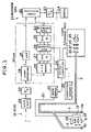
- FIG. 1is a block diagram of a main configuration of an electronic endoscope according to a first embodiment of the invention
- FIG. 2shows a characteristic of a spectral transmittance of a red component cut filter used in the embodiment
- FIG. 3shows focusing distances in operation of a zoom mechanism according to the embodiment
- FIGS. 4(A) , 4 (B), 4 (C), and 4 (D)show coefficients stored in a coefficient pattern memory according to the first embodiment, and applied to the distances in FIG. 3 ;
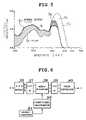
- FIG. 5shows spectral reflectance characteristics of normal gastric mucosa and blood when using a red component cut filter in the embodiment
- FIG. 6is a block diagram of a configuration according to a second embodiment
- FIG. 7shows a light illumination state (lower side) and a light distribution curve (upper side) when focusing at a distance D 1 in the second embodiment
- FIG. 8is a block diagram of a main configuration according to a third embodiment.
- FIG. 9shows a light illumination state on an image pickup surface of an image pickup device and the number of pixels that forms a unit for coefficient calculation according to a third embodiment
- FIG. 10(A)shows averages for 32 pixels on a central line Lc in FIG. 9 ;
- FIG. 10(B)shows coefficients for 32 on a central line Lc in FIG. 9 ;
- FIG. 11is a block diagram of a main configuration according to a fourth embodiment.
- FIG. 12shows a position in which a movable lens of an optical zoom mechanism according to the fourth embodiment is driven
- FIG. 13is a flowchart of operation at switch on of a microcomputer according to the fourth embodiment.
- FIG. 14is a flowchart of operation in zoom switch operation of the microcomputer according to the fourth embodiment.
- FIG. 15shows a light illumination state when a tip of a scope is brought close to an object to be observed
- FIG. 16shows a display state of the object to be observed in FIG. 15 .
- FIG. 1shows a configuration of an electronic endoscope according to a first embodiment.
- the electronic endoscopeis of a simultaneous type, and includes a scope 10 , a processor unit 11 , a light source unit 12 , and a monitor 14 .
- the endoscope in FIG. 1includes, at a tip of the scope 10 , illumination windows 4 a , 4 b and an observation window 6 , and a light guide 3 guided from the light source unit 12 connects to the illumination windows 4 a , 4 b.
- the observation window 6constitutes an objective optical system
- the objective optical systemincludes a movable lens 16
- the movable lens 16is held by and connected to a moving mechanism 18 .
- a motor driving unit 22connects via a rotating linear transfer member 20
- the motor driving unit 22is controlled by a microcomputer 24 .
- the microcomputer 24rotates a motor of the motor driving unit 22 , and transfers the rotation to the moving mechanism 18 via the linear transfer member 20
- the moving mechanism 18converts the rotating motion to linear motion to move the movable lens 16 back and forth.
- the movable lens 16is driven and controlled to each position (for example, 256 control positions) from a Far end to a Near end, thus performing optical zooming.
- a CCD 26that is an image pickup device is provided, and the CCD 26 captures an image of an object to be observed through color filters (for example, Mg (magenta), G (green), Cy (cyan), and Ye (yellow)) for each pixel.
- color filtersfor example, Mg (magenta), G (green), Cy (cyan), and Ye (yellow)
- light from the light source unit 12is applied from a tip of the scope 10 via the light guide 3 to the object to be observed, thus an image of the object to be observed is captured by the CCD 26 .
- a CDS (correlated double sampling)/AGC (automatic gain control) circuit 28is provided, and this CDS/AGC 28 performs correlated double sampling and predetermined amplification processing of an output signal from the CCD 26 .
- a DSP (digital signal processor) 30is provided via an A/D (analog/digital) converter 29 .
- a pattern memory 32is provided that stores coefficient pattern (table) data corresponding to a drive lens position (focusing distance) of the movable lens 16 , and the coefficient pattern is fed to the DSP 30 by control by the microcomputer 24 that recognizes a lens position of the movable lens 16 .
- the DSP 30includes a signal processing circuit 34 for performing various kinds of processing such as white balance, or gamma correction, and forming a Y (brightness) signal and color difference (C) signals of R (red) ⁇ Y and B (blue) ⁇ Y, and a low-pass filter (LPF) 35 for passing low frequency of the Y signal.
- the Y signal and the color difference signals of R ⁇ Y and B ⁇ Yare formed by color conversion calculation from signals obtained through color filters of Mg, G, Cy, Ye of the CCD 26 .
- an RGB matrix circuit 36for converting the color difference signals into R (red), G (green), and B(blue) signals
- a first memory 37for storing the R, G, B signals output from the RGB matrix circuit 36
- a multiplier 38for multiplying each of the R, G, B signals by the coefficient read from the coefficient pattern memory 32
- a second memory 39for storing output from the multiplier 38
- a color conversion circuit 40for returning the R, G, B signals output from the second memory 39 to the color difference signals of R ⁇ Y and B ⁇ Y.
- the Y, C signalsare color converted to obtain the R, G, B signals, and the coefficient corresponding to the drive position of the movable lens 16 determined by the microcomputer 24 is read from the pattern memory 32 to multiply each of the R, G, B signals by the coefficient for each pixel.
- the processor unit 11includes a signal processing circuit 42 for inputting the Y signal and the color difference C signal output from the DSP 30 , and a D/A converter 43 , and in the signal processing circuit 42 , various kinds of signal processing for output to the monitor 14 are performed.
- the light source unit 12includes a lamp 45 , a red component cut filter 46 , a light amount aperture 47 , and a condenser 48 , and light output from the condenser 48 is fed to the light guide 3 .
- FIG. 2shows a spectral transmittance characteristic of the red component cut filter 46 , and the filter 46 has a characteristic that a spectral transmittance becomes half at 630 nm ( ⁇ 10 nm) and zero at 670 nm. As shown in FIG. 2 , the red component cut filter 46 cuts more than half of wavelength components of 630 nm and higher in output light from the lamp 45 .
- the first embodimentis configured as described above, and operation thereof will be described below.
- operating the zoom switch provided at the operating portion of the scope 10 or the likecauses the movable lens 16 to move back and forth, thus providing an optically enlarged image.
- the movable lens 16is moved from the Far position toward the Near position, the focusing position is shifted to a close up side, and a distance between the tip of the scope and the object to be observed becomes extremely short.
- the signal processing circuit 34performs various kinds of image processing of a video signal to form the Y (brightness) signal and the C (color difference) signal of R ⁇ Y and B ⁇ Y, and the Y signal is fed to the signal processing circuit 42 via the LPF 35 .
- the C signalis converted to the R, G, B signals in the RGB matrix 36 and stored in the first memory 37 , and the multiplier 38 multiplies the R, G, B signals read from the first memory 37 by the coefficient.
- the multiplier 38multiplies the R, G, B signals read from the first memory 37 by the coefficient.
- coefficientsare set to 1.25 at a central position, 1.18 at edges of illumination areas of lights S 1 , S 2 , 1.10 at right and left ends on a central horizontal line Lb, and coefficients are set to 1.28 at a central position, 1.18 at edges of the illumination areas of the lights S 1 , S 2 , 1.12 at right and left ends on upper and lower horizontal lines La, Lc.
- Other coefficientsare set as shown in FIGS. 4(B) to 4(D) , and for example, all coefficients are 1 at the distance D n and longer distances (no coefficient calculation is performed).
- the multiplier 38multiplies the R, G, B signals by such coefficients.
- the output from the multiplier 38is once stored in the second memory 39 , and returned to the C signal in the color conversion circuit 40 , and fed to the signal processing circuit 42 .
- performing other kinds of processing and an output processingcauses the image of the object to be observed to be displayed on the monitor 14 via the D/A converter 43 . This eliminates unevenness of light illumination resulting from varying light distribution depending on focusing distances (power) in the image enlarged by the zoom mechanism. The focusing distances (or enlargement ratios) are displayed on the monitor 14 .
- FIG. 5shows spectral reflectances of mucosa and blood when the red component cut filter 46 is placed in the light source unit 12 , and in this embodiment, the red component cut filter 46 satisfactorily eliminates the image with redness.
- a spectral reflectance curve of normal gastric mucosais denoted by C 1 (solid line)
- a spectral reflectance curve of bloodis denoted by C 2 (dotted line)
- the spectral reflectance curve C 2 of the bloodsignificantly increases at wavelengths of 600 nm and higher.
- An area S 1 surrounded by the curves C 1 and C 2 of wavelengths from 400 nm to near 600 nmshows a component that contributes to contrast between the mucosa, the blood, and other tissue
- an area S 2 surrounded by the curves C 1 and C 2 of wavelengths from near 600 nm and highershows a component that causes light scattering in a lower layer of the mucosa, and reduces the contrast between the mucosa and the blood.
- providing the red component cut filter 46causes a wavelength band from near 670 nm and higher to be removed, thus reducing a size of the area S 2 to a size of the area S 3 .
- Thisoffers advantages of reducing a red component in the image and removing a wavelength component that causes reduction in contrast between the mucosa and the blood, and displaying them in good contrast.
- the red component cut filter 46is used, the light amount becomes insufficient and the light distribution characteristic changes, but the insufficiency of the light amount (and light distribution characteristic) is eliminated by coefficient multiplication to improve both the uneven brightness and the redness of the image.
- FIG. 6shows a configuration of a second embodiment, and in this embodiment, a coefficient for even brightness does not depend on pattern memory, but is calculated in each case.
- a coefficient calculation circuit 50for feeding a coefficient to a multiplier 38 , and a microcomputer 51 for controlling the coefficient calculation circuit 50 , and the coefficient calculation circuit 50 calculates a coefficient curve (an inversion curve of a light distribution curve) corresponding to a lens position (focusing distance) of a movable lens 18 .
- FIG. 7shows a light distribution curve and a light illumination state when focusing at a distance D 1 in FIG. 3
- the light distribution curvecan be obtained by applying an interval d between central positions O 1 , O 2 in illumination areas of lights S 1 , S 2 determined by the focusing distance, and a radius r of the light illumination area, to an arithmetic equation.
- values of d, r corresponding to the position of the movable lens 16 and the arithmetic equationare stored in a memory, and when focus is achieved at the distance D 1 , values of an interval d 1 and r 1 are used to obtain a curve Kf on a central horizontal line Lf, and a curve Ke on an upper horizontal line Le in the coefficient calculation circuit 50 .
- Inversion signals (coefficient curves) of the curves Ke, Kfare fed to R, G, B signals by a multiplier 38 , thus eliminating unevenness of light illumination resulting from varying light distribution depending on enlargement ratios.
- the light illumination state in FIG. 7occurs when the movable lens 16 is at a Near end side, and brightness of the image at this time is uneven.
- the illumination areas of the lights S 1 , S 2 and a central portion of a Z area to which no light is directly appliedare compared, and when the difference is more than half of a predetermined signal level value in the image, the coefficient calculation is performed, and when the difference is less than half thereof, the coefficient calculation is not performed.
- the coefficient calculationmay be performed manually by a switch separately provided.
- the R, G, B signals formed in the RGB matrix circuit 36is multiplied by the coefficient, but an influence of the light distribution can be similarly improved also by multiplying a Y signal and color difference signals (R ⁇ Y and B ⁇ Y) output from the signal processing circuit 34 by the coefficient.
- the image signalis multiplied by the coefficient set according to the focusing distance by the movable lens and in view of the light distribution of the illumination light, to eliminate the uneven brightness of the image resulting from the varying light distribution in operation of the zoom mechanism, thus providing the image with even brightness without any influence of the light distribution in enlargement photography.
- Using the red component cut filterallows satisfactory improvement in the image with redness in the area to which no light is applied. This further removes the wavelength component that causes reduction in contrast between the mucosa and the blood, and displays them in good contrast to provide an enlarged image that is easy to observe.
- FIG. 8shows a main configuration of an electronic endoscope (scope) according to a third embodiment, and the configuration is similar to the configuration of the first embodiment except for a DSP (digital signal processor) 130 and a microcomputer 124 for controlling the DSP 130 .
- the DSP 130 for inputting a video signal from an A/D converter 29includes a signal processing circuit 132 for performing various kinds of processing such as white balance, or gamma correction, and in the signal processing circuit 132 , a Y (brightness) signal and color difference (C) signals of R (red) ⁇ Y and B (blue) ⁇ Y are formed by color conversion calculation from signals obtained through color filters of Mg, G, Cy, Ye of a CCD 26 .
- a line memory 133for storing the Y signal output from the signal processing circuit 132 for each horizontal line, an averaging circuit 134 for successively determining averages, for example, for 32 pixels (a different number of pixels is acceptable), of a horizontal line signal read from the line memory 133 , a line memory 135 for successively storing the averages calculated by the averaging circuit 134 , and a coefficient calculation unit 136 for comparing average data of the line memory 135 and calculating coefficients for matching levels of the averages with a predetermined level.
- FIG. 9shows averaged pixels in the CCD 26 .
- a screen area of, for example, 768 pixels and 494 linesis set, and on the horizontal line of 768 pixels, averages of the Y signal for 32 pixels are calculated by the averaging circuit 134 . Therefore, averages of 24 blocks are obtained, and coefficients for the 24 averages to be constant (even) are determined by the coefficient calculation unit 136 .
- FIG. 10(A)shows the averages for 32 pixels on the horizontal line in FIG. 9 .
- a value of the averagebecomes lower at a position closer to the center, and the average distribution corresponds to the light distribution.
- Coefficients for matching the averages with a maximum e 1are determined in the coefficient calculation unit 136 , and coefficients as shown in FIG. 10(B) are obtained for 32 pixels. In the coefficient calculation, coefficients for matching the averages with an average e 2 rather than the maximum e 1 may be determined.
- an RGB matrix circuit 138for converting the color difference signal output from the signal processing circuit 132 into R (red), G (green), and B(blue) signals, a multiplier 139 for multiplying the R, G, B signals output from the RGB matrix circuit 138 by the coefficients output from the coefficient calculation unit 136 , and a color conversion circuit 140 for returning the R, G, B signals output from the multiplier 139 to the color difference signals of R ⁇ Y, and B ⁇ Y.
- the multiplier 139multiplies each of the R, G, B signals by the coefficients obtained from the Y signal for 32 pixels on the horizontal line, thus eliminating the influence of the light distribution.
- the brightness (Y) signal output from the signal processing circuit 132 and the color difference (C) signal output from the color conversion circuit 140are fed to a signal processing circuit 42 of a process or unit 11 .
- a red component cut filter 46 having a characteristic in FIG. 2may be provided as described above.
- the third embodimentis configured as described above, and operation thereof will be described below.
- a zoom switchcauses a movable lens 16 to move from a Far position toward a Near position, a focusing position is shifted to a close up side, a tip of a scope is brought close to an object to be observed, and the light distribution of illumination light applied to the object to be observed changes depending on focusing distances.
- the signal processing circuit 132performs various kinds of image processing of the video signal to form the Y (brightness) signal and the C (color difference) signal of R ⁇ Y and B ⁇ Y.
- the Y signalis stored in the line memory 133 for each horizontal line, and in the next averaging circuit 134 , Y signal data of the horizontal line is averaged for 32 pixels with reference to FIG. 9 .
- 24 averages for 24 blocks (768 pixels)are stored in the line memory 135 , and the averages are compared in the next coefficient calculation unit 136 , and for example, the coefficients for matching the averages with the maximum e 1 in FIG. 10(A) are calculated.
- This coefficient calculationis performed when a difference between the averages for each block is more than a certain value (threshold value), and for example, the coefficients as shown in FIG. 10(B) are calculated.
- the coefficientsare fed to the multiplier 139 .
- FIG. 9shows a state in which illumination lights S 1 , S 2 do not overlap in close up photography and no light is applied to a central portion, and on the central line Lc in FIG. 9 , the light distribution is as shown in FIG. 10(A) .
- the coefficients for matching each average with the maximum e 1become 1.00, 1.00, 1.10, 1.10, 1.15, 1.20, 1.25 . . . for 32 pixels, and the R, G, B signals are multiplied by these coefficients as shown in the figure. This eliminates an influence of variation of the illumination light resulting from the light distribution in FIG. 10(A) .
- the R, G, B signals output from the multiplier 139are returned to the C signal in the color conversion circuit 140 , and fed to a signal processing circuit 142 in FIG. 1 .
- the image of the object to be observedis displayed on the monitor 14 , and unevenness of light illumination resulting from varying light distribution depending on focusing distances (power) is eliminated in the image enlarged by the zoom mechanism.
- the calculation and the multiplication of the coefficientsis not performed when the movable lens 16 is at the Far end in the zoom mechanism, but is started at a lens position when the movable lens 16 is driven from the Far end toward the Near end, or a predetermined lens position (for example, an intermediate lens position). Specifically, an influence of the light distribution of the illumination light on brightness of the image in close up photography in zoom operation is eliminated.
- providing the red component cut filter 46causes a wavelength band from near 670 nm and higher to be removed, thus reducing a size of the area S 2 to a size of the area S 3 with reference to FIG. 5 .
- the red component cut filter 46is used, the light amount becomes insufficient and the light distribution characteristic changes, but the insufficiency of the light amount (and light distribution characteristic) is eliminated by the coefficient multiplication to improve both the uneven brightness and the redness of the image.
- the R, G, B signals formed in the RGB matrix circuit 138are multiplied by the coefficients, but the influence of the light distribution can be similarly improved by multiplying the color difference signals (R ⁇ Y and B ⁇ Y) output from the signal processing circuit 132 by the coefficients.
- the brightness signals for a predetermined number of pixelsare averaged, and the averages are compared for each horizontal line, the coefficients for the averages to be even are calculated, and the color signal is multiplied by the coefficients for the predetermined number of pixels, thus eliminating the influence of varying light distribution in enlargement photography to provide an image of uniform brightness.
- FIG. 11shows a main configuration of an electronic endoscope (scope) according to a fourth embodiment, and the configuration is similar to the configuration of the first embodiment except for the configuration in this drawing.
- a scope 10includes a color data memory 234 for storing gain data for amplifying a standard color signal and gain data for reducing an R (red) signal level in operation to a close up photography area (in this embodiment, in extreme close up photography (in Near end driving)), or the like, and a microcomputer 236 for collectively controlling the entire parts.
- a DSP 230 for inputting a video signal from an A/D converter 29includes a signal processing circuit 238 for performing various kinds of processing such as white balance, or gamma correction, and forming a Y (brightness) signal and color difference (C) signals of R (red) ⁇ Y and B (blue) ⁇ Y, and a low-pass filter (LPF) 239 for passing low frequency of the Y signal.
- the Y signal and the color difference signals of R ⁇ Y and B ⁇ Yare formed by color conversion calculation from signals obtained through color filters of Mg, G, Cy, Ye of a CCD 26 .
- an RGB matrix circuit 240for converting the color difference (C) signals into R (red), G (green), and B(blue) signals, an amplifier 241 for reducing a level of the R signal only based on an R gain in extreme close up photography stored in the color data memory 234 , and a color conversion circuit 242 for returning the R, G, B signals to the color difference signals of R ⁇ Y, and B ⁇ Y.
- the Y and C signalsare color converted to obtain the R signal, and when the microcomputer 236 determines that a movable lens 16 is at a Near end (CN) in FIG. 12 , the R signal is amplified by the R gain in the extreme close up photography, and for example, the signal level is reduced to 1 ⁇ 2.
- the brightness (Y) signal and the color difference (C) signals output from the DSP 230are fed to a signal processing circuit 42 in a processor unit 11 .
- FIG. 13shows operation by the microcomputer 236 at switch on, and when the power switch of the processor unit 11 is turned on, operation setting is initialized.
- Step S 11the movable lens 16 is driven to a Far position by zoom portion initializing, and in next Step S 12 , standard color data is set.
- Step S 12standard color data is set.
- an output signal from the CCD 26is fed via a CDS/AGC 28 and an A/D converter 29 to a DSP 130 as digital signals.
- the signal processing circuit 238performs various kinds of image processing of a video signal to form the Y (brightness) signal and the C (color difference) signals of R ⁇ Y and B ⁇ Y, and the Y signal is fed to the processor unit 11 via the LPF 239 .
- the C signalis fed to the process or unit 11 via the RGB matrix 240 , the amplifier 241 , and the color conversion circuit 242 , but the R, G, B signals are amplified by the amplifier 141 based on standard color data other than in the extreme close up photography.
- operating a zoom switch placed at an operating portion or the likecauses the movable lens 16 to move toward the Near end Cn in FIG. 12 , thus providing an enlarged image focusing on the object to be observed to which the tip of the scope is brought close.
- FIG. 14shows operation of the microcomputer 236 relating to the operation of the zoom switch.
- the zoom switchWhen the zoom switch is operated (turned on), it is determined whether the movable lens 16 is at the Near end in Step S 21 , and when Y (YES), color data in the extreme close up photography is set in Step S 23 .
- an amplification ratio of the R signalFor the color data in the extreme close up photography, an amplification ratio of the R signal only is 1 ⁇ 2 of, for example, the standard color data.
- an image with half the R signal level as compared with other photographyis formed. This eliminates a red tone of the image shown in FIG. 15 , and improves the image with redness.
- Step S 21 in FIG. 14when N (NO), that is, when the movable lens 16 is not at the Near end (Cn), it is determined that the color data in the extreme close up photography is now set in Step S 23 , and when Y, the standard color data is set in Step S 24 .
- NNO
- the color data in the extreme close up photographyis switched to the standard color data to perform standard image processing.
- the R signal level of the R, G, B signalsis reduced in the extreme close up photography, but similar advantages can be obtained by reducing the R ⁇ Y signal level of the color difference signal.
- the red levelis reduced when the movable lens 16 is driven to the Near end (Cn), but a reduction start position of the red level may extend to a position of Cp (close up photography are) before the Near end Cn in FIG. 12 .
- the R, G, B signalscan be directly formed rather than conversion from the color difference signals in the DSP 130 , and in such a case, the amplification of the R signal by the R gain may be performed.
- the image with rednesscan be improved that occurs in enlarged image photography in which the tip of the scope is brought extremely close to the object to be observed, thus providing a close up enlarged image that is easy to observe.
Landscapes
- Health & Medical Sciences (AREA)
- Life Sciences & Earth Sciences (AREA)
- Surgery (AREA)
- Physics & Mathematics (AREA)
- Engineering & Computer Science (AREA)
- Biophysics (AREA)
- Veterinary Medicine (AREA)
- Optics & Photonics (AREA)
- Pathology (AREA)
- Public Health (AREA)
- General Health & Medical Sciences (AREA)
- Biomedical Technology (AREA)
- Heart & Thoracic Surgery (AREA)
- Medical Informatics (AREA)
- Molecular Biology (AREA)
- Animal Behavior & Ethology (AREA)
- Radiology & Medical Imaging (AREA)
- Nuclear Medicine, Radiotherapy & Molecular Imaging (AREA)
- Signal Processing (AREA)
- Astronomy & Astrophysics (AREA)
- General Physics & Mathematics (AREA)
- Instruments For Viewing The Inside Of Hollow Bodies (AREA)
- Endoscopes (AREA)
Abstract
Description
Claims (8)
Applications Claiming Priority (6)
| Application Number | Priority Date | Filing Date | Title |
|---|---|---|---|
| JP2001299226AJP4012384B2 (en) | 2001-09-28 | 2001-09-28 | Electronic endoscope apparatus with optical zoom mechanism |
| JP2001-299227 | 2001-09-28 | ||
| JP2001299227AJP3962564B2 (en) | 2001-09-28 | 2001-09-28 | Electronic endoscope apparatus with optical zoom mechanism |
| JP2001-301804 | 2001-09-28 | ||
| JP2001301804AJP2003102676A (en) | 2001-09-28 | 2001-09-28 | Electronic endoscope apparatus having optical variable power function |
| JP2001-299226 | 2001-09-28 |
Publications (2)
| Publication Number | Publication Date |
|---|---|
| US20030063398A1 US20030063398A1 (en) | 2003-04-03 |
| US7123288B2true US7123288B2 (en) | 2006-10-17 |
Family
ID=27347600
Family Applications (1)
| Application Number | Title | Priority Date | Filing Date |
|---|---|---|---|
| US10/259,282Expired - Fee RelatedUS7123288B2 (en) | 2001-09-28 | 2002-09-27 | Electronic endoscope eliminating influence of light distribution in optical zooming |
Country Status (1)
| Country | Link |
|---|---|
| US (1) | US7123288B2 (en) |
Cited By (35)
| Publication number | Priority date | Publication date | Assignee | Title |
|---|---|---|---|---|
| US20080062261A1 (en)* | 2004-06-17 | 2008-03-13 | Masaru Sudo | Endoscope apparatus |
| US20090109284A1 (en)* | 2007-10-29 | 2009-04-30 | Hoya Corporation | Electronic endoscope signal-processing device and electronic endoscope system |
| US9101268B2 (en) | 2009-06-18 | 2015-08-11 | Endochoice Innovation Center Ltd. | Multi-camera endoscope |
| US9101266B2 (en) | 2011-02-07 | 2015-08-11 | Endochoice Innovation Center Ltd. | Multi-element cover for a multi-camera endoscope |
| US9101287B2 (en) | 2011-03-07 | 2015-08-11 | Endochoice Innovation Center Ltd. | Multi camera endoscope assembly having multiple working channels |
| US9314147B2 (en) | 2011-12-13 | 2016-04-19 | Endochoice Innovation Center Ltd. | Rotatable connector for an endoscope |
| US9320419B2 (en) | 2010-12-09 | 2016-04-26 | Endochoice Innovation Center Ltd. | Fluid channeling component of a multi-camera endoscope |
| US9402533B2 (en) | 2011-03-07 | 2016-08-02 | Endochoice Innovation Center Ltd. | Endoscope circuit board assembly |
| US9492063B2 (en) | 2009-06-18 | 2016-11-15 | Endochoice Innovation Center Ltd. | Multi-viewing element endoscope |
| US9554692B2 (en) | 2009-06-18 | 2017-01-31 | EndoChoice Innovation Ctr. Ltd. | Multi-camera endoscope |
| US9560953B2 (en) | 2010-09-20 | 2017-02-07 | Endochoice, Inc. | Operational interface in a multi-viewing element endoscope |
| US9560954B2 (en) | 2012-07-24 | 2017-02-07 | Endochoice, Inc. | Connector for use with endoscope |
| US9642513B2 (en) | 2009-06-18 | 2017-05-09 | Endochoice Inc. | Compact multi-viewing element endoscope system |
| US9655502B2 (en) | 2011-12-13 | 2017-05-23 | EndoChoice Innovation Center, Ltd. | Removable tip endoscope |
| US9706903B2 (en) | 2009-06-18 | 2017-07-18 | Endochoice, Inc. | Multiple viewing elements endoscope system with modular imaging units |
| US9713417B2 (en) | 2009-06-18 | 2017-07-25 | Endochoice, Inc. | Image capture assembly for use in a multi-viewing elements endoscope |
| US9713415B2 (en) | 2011-03-07 | 2017-07-25 | Endochoice Innovation Center Ltd. | Multi camera endoscope having a side service channel |
| US9814374B2 (en) | 2010-12-09 | 2017-11-14 | Endochoice Innovation Center Ltd. | Flexible electronic circuit board for a multi-camera endoscope |
| US9872609B2 (en) | 2009-06-18 | 2018-01-23 | Endochoice Innovation Center Ltd. | Multi-camera endoscope |
| US9901244B2 (en) | 2009-06-18 | 2018-02-27 | Endochoice, Inc. | Circuit board assembly of a multiple viewing elements endoscope |
| US9986899B2 (en) | 2013-03-28 | 2018-06-05 | Endochoice, Inc. | Manifold for a multiple viewing elements endoscope |
| US9993142B2 (en) | 2013-03-28 | 2018-06-12 | Endochoice, Inc. | Fluid distribution device for a multiple viewing elements endoscope |
| US10080486B2 (en) | 2010-09-20 | 2018-09-25 | Endochoice Innovation Center Ltd. | Multi-camera endoscope having fluid channels |
| US10165929B2 (en) | 2009-06-18 | 2019-01-01 | Endochoice, Inc. | Compact multi-viewing element endoscope system |
| US10203493B2 (en) | 2010-10-28 | 2019-02-12 | Endochoice Innovation Center Ltd. | Optical systems for multi-sensor endoscopes |
| US10499794B2 (en) | 2013-05-09 | 2019-12-10 | Endochoice, Inc. | Operational interface in a multi-viewing element endoscope |
| US11278190B2 (en) | 2009-06-18 | 2022-03-22 | Endochoice, Inc. | Multi-viewing element endoscope |
| US11547275B2 (en) | 2009-06-18 | 2023-01-10 | Endochoice, Inc. | Compact multi-viewing element endoscope system |
| US11559186B2 (en) | 2015-08-13 | 2023-01-24 | Hoya Corporation | Evaluation value calculation device and electronic endoscope system |
| US11571108B2 (en) | 2015-08-13 | 2023-02-07 | Hoya Corporation | Evaluation value calculation device and electronic endoscope system |
| US11864734B2 (en) | 2009-06-18 | 2024-01-09 | Endochoice, Inc. | Multi-camera endoscope |
| US11889986B2 (en) | 2010-12-09 | 2024-02-06 | Endochoice, Inc. | Flexible electronic circuit board for a multi-camera endoscope |
| US12137873B2 (en) | 2009-06-18 | 2024-11-12 | Endochoice, Inc. | Compact multi-viewing element endoscope system |
| US12204087B2 (en) | 2010-10-28 | 2025-01-21 | Endochoice, Inc. | Optical systems for multi-sensor endoscopes |
| US12220105B2 (en) | 2010-06-16 | 2025-02-11 | Endochoice, Inc. | Circuit board assembly of a multiple viewing elements endoscope |
Families Citing this family (44)
| Publication number | Priority date | Publication date | Assignee | Title |
|---|---|---|---|---|
| EP1637064A4 (en)* | 2003-06-24 | 2010-07-28 | Olympus Corp | Encapsulated endoscope and encapsulated endoscope system |
| TW581668B (en)* | 2003-10-15 | 2004-04-01 | Der-Yang Tien | Endoscopic device |
| US7420151B2 (en)* | 2005-10-17 | 2008-09-02 | Novadaq Technologies Inc. | Device for short wavelength visible reflectance endoscopy using broadband illumination |
| US20070161854A1 (en)* | 2005-10-26 | 2007-07-12 | Moshe Alamaro | System and method for endoscopic measurement and mapping of internal organs, tumors and other objects |
| US8498695B2 (en) | 2006-12-22 | 2013-07-30 | Novadaq Technologies Inc. | Imaging system with a single color image sensor for simultaneous fluorescence and color video endoscopy |
| US9474440B2 (en) | 2009-06-18 | 2016-10-25 | Endochoice, Inc. | Endoscope tip position visual indicator and heat management system |
| US10524645B2 (en) | 2009-06-18 | 2020-01-07 | Endochoice, Inc. | Method and system for eliminating image motion blur in a multiple viewing elements endoscope |
| US10130246B2 (en) | 2009-06-18 | 2018-11-20 | Endochoice, Inc. | Systems and methods for regulating temperature and illumination intensity at the distal tip of an endoscope |
| US9706908B2 (en) | 2010-10-28 | 2017-07-18 | Endochoice, Inc. | Image capture and video processing systems and methods for multiple viewing element endoscopes |
| US10663714B2 (en) | 2010-10-28 | 2020-05-26 | Endochoice, Inc. | Optical system for an endoscope |
| EP2661211B1 (en)* | 2011-01-05 | 2022-03-30 | Bar-Ilan University | Imaging system and method using multicore fiber |
| US10517464B2 (en) | 2011-02-07 | 2019-12-31 | Endochoice, Inc. | Multi-element cover for a multi-camera endoscope |
| US12207796B2 (en) | 2013-03-28 | 2025-01-28 | Endochoice Inc. | Multi-jet controller for an endoscope |
| US9636003B2 (en) | 2013-06-28 | 2017-05-02 | Endochoice, Inc. | Multi-jet distributor for an endoscope |
| US10595714B2 (en) | 2013-03-28 | 2020-03-24 | Endochoice, Inc. | Multi-jet controller for an endoscope |
| WO2014182723A1 (en) | 2013-05-07 | 2014-11-13 | Endochoice, Inc. | White balance enclosed for use with a multi-viewing elements endoscope |
| US9949623B2 (en) | 2013-05-17 | 2018-04-24 | Endochoice, Inc. | Endoscope control unit with braking system |
| US10064541B2 (en) | 2013-08-12 | 2018-09-04 | Endochoice, Inc. | Endoscope connector cover detection and warning system |
| US9943218B2 (en) | 2013-10-01 | 2018-04-17 | Endochoice, Inc. | Endoscope having a supply cable attached thereto |
| US9968242B2 (en) | 2013-12-18 | 2018-05-15 | Endochoice, Inc. | Suction control unit for an endoscope having two working channels |
| WO2015112747A2 (en) | 2014-01-22 | 2015-07-30 | Endochoice, Inc. | Image capture and video processing systems and methods for multiple viewing element endoscopes |
| JP2015184623A (en)* | 2014-03-26 | 2015-10-22 | ソニー株式会社 | Image display device, color filter, and image signal processor |
| US11234581B2 (en) | 2014-05-02 | 2022-02-01 | Endochoice, Inc. | Elevator for directing medical tool |
| EP3689219B1 (en) | 2014-07-21 | 2023-08-30 | EndoChoice, Inc. | Multi-focal, multi-camera endoscope systems |
| US10542877B2 (en) | 2014-08-29 | 2020-01-28 | Endochoice, Inc. | Systems and methods for varying stiffness of an endoscopic insertion tube |
| EP3235241B1 (en)* | 2014-12-18 | 2023-09-06 | EndoChoice, Inc. | System for processing video images generated by a multiple viewing elements endoscope |
| WO2016112034A2 (en) | 2015-01-05 | 2016-07-14 | Endochoice, Inc. | Tubed manifold of a multiple viewing elements endoscope |
| US10376181B2 (en) | 2015-02-17 | 2019-08-13 | Endochoice, Inc. | System for detecting the location of an endoscopic device during a medical procedure |
| US10078207B2 (en) | 2015-03-18 | 2018-09-18 | Endochoice, Inc. | Systems and methods for image magnification using relative movement between an image sensor and a lens assembly |
| US10401611B2 (en) | 2015-04-27 | 2019-09-03 | Endochoice, Inc. | Endoscope with integrated measurement of distance to objects of interest |
| US10516865B2 (en) | 2015-05-17 | 2019-12-24 | Endochoice, Inc. | Endoscopic image enhancement using contrast limited adaptive histogram equalization (CLAHE) implemented in a processor |
| US20170119474A1 (en) | 2015-10-28 | 2017-05-04 | Endochoice, Inc. | Device and Method for Tracking the Position of an Endoscope within a Patient's Body |
| AU2016351730B2 (en) | 2015-11-13 | 2019-07-11 | Novadaq Technologies Inc. | Systems and methods for illumination and imaging of a target |
| EP4579310A3 (en) | 2015-11-24 | 2025-09-10 | Endochoice, Inc. | Disposable air/water and suction valves for an endoscope |
| WO2017127929A1 (en) | 2016-01-26 | 2017-08-03 | Novadaq Technologies Inc. | Configurable platform |
| JP2019507628A (en) | 2016-02-24 | 2019-03-22 | エンドチョイス インコーポレイテッドEndochoice, Inc. | Circuit board assembly for multiple view element endoscopes using CMOS sensors |
| US10292570B2 (en) | 2016-03-14 | 2019-05-21 | Endochoice, Inc. | System and method for guiding and tracking a region of interest using an endoscope |
| USD916294S1 (en) | 2016-04-28 | 2021-04-13 | Stryker European Operations Limited | Illumination and imaging device |
| EP3469420A4 (en) | 2016-06-14 | 2020-02-12 | Novadaq Technologies ULC | METHODS AND SYSTEMS FOR ADAPTIVE IMAGING FOR THE AMPLIFICATION OF A WEAK LIGHT SIGNAL IN A MEDICAL VISUALIZATION |
| EP3429478B1 (en) | 2016-06-21 | 2021-04-21 | Endochoice, Inc. | Endoscope system with multiple connection interfaces to interface with different video data signal sources |
| EP3580609B1 (en) | 2017-02-10 | 2023-05-24 | Stryker European Operations Limited | Open-field handheld fluorescence imaging systems and methods |
| JP2019201887A (en) | 2018-05-23 | 2019-11-28 | オリンパス株式会社 | Endoscope image processing device and endoscope system |
| EP3620098B1 (en)* | 2018-09-07 | 2021-11-03 | Ambu A/S | Enhancing the visibility of blood vessels in colour images |
| WO2020059098A1 (en)* | 2018-09-20 | 2020-03-26 | オリンパス株式会社 | Image processor |
Citations (6)
| Publication number | Priority date | Publication date | Assignee | Title |
|---|---|---|---|---|
| JPH01223932A (en) | 1988-03-03 | 1989-09-07 | Toshiba Corp | endoscope equipment |
| US4953937A (en)* | 1988-05-17 | 1990-09-04 | Olympus Optical Co., Ltd. | Illumination optical system |
| US5339159A (en)* | 1991-10-02 | 1994-08-16 | Olympus Optical Co., Ltd. | Color misregistration detector and color misregistration easing system |
| US5582576A (en)* | 1992-10-28 | 1996-12-10 | Oktas General Partnership | Electronic endoscope with zoom lens system |
| JP2000037345A (en) | 1998-05-18 | 2000-02-08 | Fuji Photo Optical Co Ltd | Endoscope observation system |
| US20020147383A1 (en)* | 2001-04-04 | 2002-10-10 | Richard Wolf Gmbh | Device for the picture-providing diagnosis of tissue |
- 2002
- 2002-09-27USUS10/259,282patent/US7123288B2/ennot_activeExpired - Fee Related
Patent Citations (6)
| Publication number | Priority date | Publication date | Assignee | Title |
|---|---|---|---|---|
| JPH01223932A (en) | 1988-03-03 | 1989-09-07 | Toshiba Corp | endoscope equipment |
| US4953937A (en)* | 1988-05-17 | 1990-09-04 | Olympus Optical Co., Ltd. | Illumination optical system |
| US5339159A (en)* | 1991-10-02 | 1994-08-16 | Olympus Optical Co., Ltd. | Color misregistration detector and color misregistration easing system |
| US5582576A (en)* | 1992-10-28 | 1996-12-10 | Oktas General Partnership | Electronic endoscope with zoom lens system |
| JP2000037345A (en) | 1998-05-18 | 2000-02-08 | Fuji Photo Optical Co Ltd | Endoscope observation system |
| US20020147383A1 (en)* | 2001-04-04 | 2002-10-10 | Richard Wolf Gmbh | Device for the picture-providing diagnosis of tissue |
Cited By (67)
| Publication number | Priority date | Publication date | Assignee | Title |
|---|---|---|---|---|
| US20080062261A1 (en)* | 2004-06-17 | 2008-03-13 | Masaru Sudo | Endoscope apparatus |
| US7734160B2 (en)* | 2004-06-17 | 2010-06-08 | Olympus Corporation | Endoscope apparatus |
| US20090109284A1 (en)* | 2007-10-29 | 2009-04-30 | Hoya Corporation | Electronic endoscope signal-processing device and electronic endoscope system |
| US8274558B2 (en)* | 2007-10-29 | 2012-09-25 | Hoya Corporation | Electronic endoscope signal-processing device and electronic endoscope system |
| US11534056B2 (en) | 2009-06-18 | 2022-12-27 | Endochoice, Inc. | Multi-camera endoscope |
| US9713417B2 (en) | 2009-06-18 | 2017-07-25 | Endochoice, Inc. | Image capture assembly for use in a multi-viewing elements endoscope |
| US12303106B2 (en) | 2009-06-18 | 2025-05-20 | Endochoice, Inc. | Multi-camera endoscope |
| US10638922B2 (en) | 2009-06-18 | 2020-05-05 | Endochoice, Inc. | Multi-camera endoscope |
| US12137873B2 (en) | 2009-06-18 | 2024-11-12 | Endochoice, Inc. | Compact multi-viewing element endoscope system |
| US11986155B2 (en) | 2009-06-18 | 2024-05-21 | Endochoice, Inc. | Multi-viewing element endoscope |
| US11864734B2 (en) | 2009-06-18 | 2024-01-09 | Endochoice, Inc. | Multi-camera endoscope |
| US9492063B2 (en) | 2009-06-18 | 2016-11-15 | Endochoice Innovation Center Ltd. | Multi-viewing element endoscope |
| US9554692B2 (en) | 2009-06-18 | 2017-01-31 | EndoChoice Innovation Ctr. Ltd. | Multi-camera endoscope |
| US10165929B2 (en) | 2009-06-18 | 2019-01-01 | Endochoice, Inc. | Compact multi-viewing element endoscope system |
| US11547275B2 (en) | 2009-06-18 | 2023-01-10 | Endochoice, Inc. | Compact multi-viewing element endoscope system |
| US9642513B2 (en) | 2009-06-18 | 2017-05-09 | Endochoice Inc. | Compact multi-viewing element endoscope system |
| US9101268B2 (en) | 2009-06-18 | 2015-08-11 | Endochoice Innovation Center Ltd. | Multi-camera endoscope |
| US9706903B2 (en) | 2009-06-18 | 2017-07-18 | Endochoice, Inc. | Multiple viewing elements endoscope system with modular imaging units |
| US9706905B2 (en) | 2009-06-18 | 2017-07-18 | Endochoice Innovation Center Ltd. | Multi-camera endoscope |
| US12336686B2 (en) | 2009-06-18 | 2025-06-24 | Endochoice, Inc. | Multi-viewing element endoscope |
| US11278190B2 (en) | 2009-06-18 | 2022-03-22 | Endochoice, Inc. | Multi-viewing element endoscope |
| US10912445B2 (en) | 2009-06-18 | 2021-02-09 | Endochoice, Inc. | Compact multi-viewing element endoscope system |
| US10905320B2 (en) | 2009-06-18 | 2021-02-02 | Endochoice, Inc. | Multi-camera endoscope |
| US9872609B2 (en) | 2009-06-18 | 2018-01-23 | Endochoice Innovation Center Ltd. | Multi-camera endoscope |
| US9901244B2 (en) | 2009-06-18 | 2018-02-27 | Endochoice, Inc. | Circuit board assembly of a multiple viewing elements endoscope |
| US10791910B2 (en) | 2009-06-18 | 2020-10-06 | Endochoice, Inc. | Multiple viewing elements endoscope system with modular imaging units |
| US10092167B2 (en) | 2009-06-18 | 2018-10-09 | Endochoice, Inc. | Multiple viewing elements endoscope system with modular imaging units |
| US10791909B2 (en) | 2009-06-18 | 2020-10-06 | Endochoice, Inc. | Image capture assembly for use in a multi-viewing elements endoscope |
| US10765305B2 (en) | 2009-06-18 | 2020-09-08 | Endochoice, Inc. | Circuit board assembly of a multiple viewing elements endoscope |
| US12220105B2 (en) | 2010-06-16 | 2025-02-11 | Endochoice, Inc. | Circuit board assembly of a multiple viewing elements endoscope |
| US10080486B2 (en) | 2010-09-20 | 2018-09-25 | Endochoice Innovation Center Ltd. | Multi-camera endoscope having fluid channels |
| US9986892B2 (en) | 2010-09-20 | 2018-06-05 | Endochoice, Inc. | Operational interface in a multi-viewing element endoscope |
| US9560953B2 (en) | 2010-09-20 | 2017-02-07 | Endochoice, Inc. | Operational interface in a multi-viewing element endoscope |
| US10203493B2 (en) | 2010-10-28 | 2019-02-12 | Endochoice Innovation Center Ltd. | Optical systems for multi-sensor endoscopes |
| US12204087B2 (en) | 2010-10-28 | 2025-01-21 | Endochoice, Inc. | Optical systems for multi-sensor endoscopes |
| US11543646B2 (en) | 2010-10-28 | 2023-01-03 | Endochoice, Inc. | Optical systems for multi-sensor endoscopes |
| US11889986B2 (en) | 2010-12-09 | 2024-02-06 | Endochoice, Inc. | Flexible electronic circuit board for a multi-camera endoscope |
| US11497388B2 (en) | 2010-12-09 | 2022-11-15 | Endochoice, Inc. | Flexible electronic circuit board for a multi-camera endoscope |
| US10182707B2 (en) | 2010-12-09 | 2019-01-22 | Endochoice Innovation Center Ltd. | Fluid channeling component of a multi-camera endoscope |
| US9320419B2 (en) | 2010-12-09 | 2016-04-26 | Endochoice Innovation Center Ltd. | Fluid channeling component of a multi-camera endoscope |
| US10898063B2 (en) | 2010-12-09 | 2021-01-26 | Endochoice, Inc. | Flexible electronic circuit board for a multi camera endoscope |
| US9814374B2 (en) | 2010-12-09 | 2017-11-14 | Endochoice Innovation Center Ltd. | Flexible electronic circuit board for a multi-camera endoscope |
| US9101266B2 (en) | 2011-02-07 | 2015-08-11 | Endochoice Innovation Center Ltd. | Multi-element cover for a multi-camera endoscope |
| US10070774B2 (en) | 2011-02-07 | 2018-09-11 | Endochoice Innovation Center Ltd. | Multi-element cover for a multi-camera endoscope |
| US9351629B2 (en) | 2011-02-07 | 2016-05-31 | Endochoice Innovation Center Ltd. | Multi-element cover for a multi-camera endoscope |
| US9854959B2 (en) | 2011-03-07 | 2018-01-02 | Endochoice Innovation Center Ltd. | Multi camera endoscope assembly having multiple working channels |
| US11026566B2 (en) | 2011-03-07 | 2021-06-08 | Endochoice, Inc. | Multi camera endoscope assembly having multiple working channels |
| US9713415B2 (en) | 2011-03-07 | 2017-07-25 | Endochoice Innovation Center Ltd. | Multi camera endoscope having a side service channel |
| US9402533B2 (en) | 2011-03-07 | 2016-08-02 | Endochoice Innovation Center Ltd. | Endoscope circuit board assembly |
| US9101287B2 (en) | 2011-03-07 | 2015-08-11 | Endochoice Innovation Center Ltd. | Multi camera endoscope assembly having multiple working channels |
| US10292578B2 (en) | 2011-03-07 | 2019-05-21 | Endochoice Innovation Center Ltd. | Multi camera endoscope assembly having multiple working channels |
| US9655502B2 (en) | 2011-12-13 | 2017-05-23 | EndoChoice Innovation Center, Ltd. | Removable tip endoscope |
| US10470649B2 (en) | 2011-12-13 | 2019-11-12 | Endochoice, Inc. | Removable tip endoscope |
| US12290241B2 (en) | 2011-12-13 | 2025-05-06 | Endochoice, Inc. | Removable tip endoscope |
| US9314147B2 (en) | 2011-12-13 | 2016-04-19 | Endochoice Innovation Center Ltd. | Rotatable connector for an endoscope |
| US11291357B2 (en) | 2011-12-13 | 2022-04-05 | Endochoice, Inc. | Removable tip endoscope |
| US9560954B2 (en) | 2012-07-24 | 2017-02-07 | Endochoice, Inc. | Connector for use with endoscope |
| US11925323B2 (en) | 2013-03-28 | 2024-03-12 | Endochoice, Inc. | Fluid distribution device for a multiple viewing elements endoscope |
| US10925471B2 (en) | 2013-03-28 | 2021-02-23 | Endochoice, Inc. | Fluid distribution device for a multiple viewing elements endoscope |
| US10905315B2 (en) | 2013-03-28 | 2021-02-02 | Endochoice, Inc. | Manifold for a multiple viewing elements endoscope |
| US9986899B2 (en) | 2013-03-28 | 2018-06-05 | Endochoice, Inc. | Manifold for a multiple viewing elements endoscope |
| US9993142B2 (en) | 2013-03-28 | 2018-06-12 | Endochoice, Inc. | Fluid distribution device for a multiple viewing elements endoscope |
| US11793393B2 (en) | 2013-03-28 | 2023-10-24 | Endochoice, Inc. | Manifold for a multiple viewing elements endoscope |
| US12232699B2 (en) | 2013-03-28 | 2025-02-25 | Endochoice, Inc. | Manifold for a multiple viewing elements endoscope |
| US10499794B2 (en) | 2013-05-09 | 2019-12-10 | Endochoice, Inc. | Operational interface in a multi-viewing element endoscope |
| US11571108B2 (en) | 2015-08-13 | 2023-02-07 | Hoya Corporation | Evaluation value calculation device and electronic endoscope system |
| US11559186B2 (en) | 2015-08-13 | 2023-01-24 | Hoya Corporation | Evaluation value calculation device and electronic endoscope system |
Also Published As
| Publication number | Publication date |
|---|---|
| US20030063398A1 (en) | 2003-04-03 |
Similar Documents
| Publication | Publication Date | Title |
|---|---|---|
| US7123288B2 (en) | Electronic endoscope eliminating influence of light distribution in optical zooming | |
| US8237783B2 (en) | Image processing device for endoscope and endoscope apparatus | |
| US8279275B2 (en) | Signal processing device for biological observation apparatus | |
| CN101336088B (en) | endoscopic device | |
| US8979741B2 (en) | Endoscopic apparatus | |
| JP4409523B2 (en) | Biological observation device | |
| CN102740760B (en) | Endoscope device | |
| US11044416B2 (en) | Endoscope system, processor device, and endoscope system operation method | |
| US20050117028A1 (en) | Image pick-up apparatus and endoscope apparatus | |
| CN101420901A (en) | Biological observation system | |
| CN101677755A (en) | Image generation device | |
| US20160295085A1 (en) | Endoscope system, processing apparatus and endoscope operating method | |
| JP3752272B2 (en) | Electronic endoscope device | |
| US6932762B2 (en) | Endoscope having red component cut filter | |
| JP4716673B2 (en) | Fluorescence endoscope device | |
| WO2019093356A1 (en) | Endoscope system and operation method therefor | |
| JP2005033282A (en) | Imaging device | |
| JP3962564B2 (en) | Electronic endoscope apparatus with optical zoom mechanism | |
| JP4012384B2 (en) | Electronic endoscope apparatus with optical zoom mechanism | |
| JPH06285050A (en) | Endoscope system | |
| JP5856943B2 (en) | Imaging system | |
| JP2713837B2 (en) | Electronic endoscope device | |
| JP2001251613A (en) | Endoscope system | |
| JP4014726B2 (en) | Electronic endoscope apparatus and light source apparatus for electronic endoscope | |
| JP2003102676A (en) | Electronic endoscope apparatus having optical variable power function |
Legal Events
| Date | Code | Title | Description |
|---|---|---|---|
| AS | Assignment | Owner name:FUJI PHOTO OPTICAL CO., LTD., JAPAN Free format text:ASSIGNMENT OF ASSIGNORS INTEREST;ASSIGNORS:ABE, KAZUNORI;HIGUCHI, MITSURU;AYAME, DAISUKE;AND OTHERS;REEL/FRAME:013436/0214 Effective date:20020925 | |
| AS | Assignment | Owner name:FUJINON CORPORATION, JAPAN Free format text:CHANGE OF NAME;ASSIGNOR:FUJI PHOTO OPTICAL CO., LTD.;REEL/FRAME:016549/0899 Effective date:20041001 Owner name:FUJINON CORPORATION,JAPAN Free format text:CHANGE OF NAME;ASSIGNOR:FUJI PHOTO OPTICAL CO., LTD.;REEL/FRAME:016549/0899 Effective date:20041001 | |
| FEPP | Fee payment procedure | Free format text:PAYER NUMBER DE-ASSIGNED (ORIGINAL EVENT CODE: RMPN); ENTITY STATUS OF PATENT OWNER: LARGE ENTITY Free format text:PAYOR NUMBER ASSIGNED (ORIGINAL EVENT CODE: ASPN); ENTITY STATUS OF PATENT OWNER: LARGE ENTITY | |
| FPAY | Fee payment | Year of fee payment:4 | |
| FPAY | Fee payment | Year of fee payment:8 | |
| FEPP | Fee payment procedure | Free format text:MAINTENANCE FEE REMINDER MAILED (ORIGINAL EVENT CODE: REM.) | |
| LAPS | Lapse for failure to pay maintenance fees | Free format text:PATENT EXPIRED FOR FAILURE TO PAY MAINTENANCE FEES (ORIGINAL EVENT CODE: EXP.); ENTITY STATUS OF PATENT OWNER: LARGE ENTITY | |
| STCH | Information on status: patent discontinuation | Free format text:PATENT EXPIRED DUE TO NONPAYMENT OF MAINTENANCE FEES UNDER 37 CFR 1.362 | |
| FP | Lapsed due to failure to pay maintenance fee | Effective date:20181017 |