US7123204B2 - Energy source communication employing slot antenna - Google Patents
Energy source communication employing slot antennaDownload PDFInfo
- Publication number
- US7123204B2 US7123204B2US10/422,609US42260903AUS7123204B2US 7123204 B2US7123204 B2US 7123204B2US 42260903 AUS42260903 AUS 42260903AUS 7123204 B2US7123204 B2US 7123204B2
- Authority
- US
- United States
- Prior art keywords
- wireless communication
- communication device
- slot
- energy source
- battery
- Prior art date
- Legal status (The legal status is an assumption and is not a legal conclusion. Google has not performed a legal analysis and makes no representation as to the accuracy of the status listed.)
- Expired - Lifetime
Links
Images


Classifications
- H—ELECTRICITY
- H01—ELECTRIC ELEMENTS
- H01Q—ANTENNAS, i.e. RADIO AERIALS
- H01Q1/00—Details of, or arrangements associated with, antennas
- H01Q1/12—Supports; Mounting means
- H01Q1/22—Supports; Mounting means by structural association with other equipment or articles
- H01Q1/2208—Supports; Mounting means by structural association with other equipment or articles associated with components used in interrogation type services, i.e. in systems for information exchange between an interrogator/reader and a tag/transponder, e.g. in Radio Frequency Identification [RFID] systems
- H01Q1/2225—Supports; Mounting means by structural association with other equipment or articles associated with components used in interrogation type services, i.e. in systems for information exchange between an interrogator/reader and a tag/transponder, e.g. in Radio Frequency Identification [RFID] systems used in active tags, i.e. provided with its own power source or in passive tags, i.e. deriving power from RF signal
- G—PHYSICS
- G06—COMPUTING OR CALCULATING; COUNTING
- G06K—GRAPHICAL DATA READING; PRESENTATION OF DATA; RECORD CARRIERS; HANDLING RECORD CARRIERS
- G06K19/00—Record carriers for use with machines and with at least a part designed to carry digital markings
- G06K19/06—Record carriers for use with machines and with at least a part designed to carry digital markings characterised by the kind of the digital marking, e.g. shape, nature, code
- G06K19/067—Record carriers with conductive marks, printed circuits or semiconductor circuit elements, e.g. credit or identity cards also with resonating or responding marks without active components
- G06K19/07—Record carriers with conductive marks, printed circuits or semiconductor circuit elements, e.g. credit or identity cards also with resonating or responding marks without active components with integrated circuit chips
- G06K19/077—Constructional details, e.g. mounting of circuits in the carrier
- G06K19/07749—Constructional details, e.g. mounting of circuits in the carrier the record carrier being capable of non-contact communication, e.g. constructional details of the antenna of a non-contact smart card
- H—ELECTRICITY
- H01—ELECTRIC ELEMENTS
- H01Q—ANTENNAS, i.e. RADIO AERIALS
- H01Q1/00—Details of, or arrangements associated with, antennas
- H01Q1/12—Supports; Mounting means
- H01Q1/22—Supports; Mounting means by structural association with other equipment or articles
- H—ELECTRICITY
- H01—ELECTRIC ELEMENTS
- H01Q—ANTENNAS, i.e. RADIO AERIALS
- H01Q1/00—Details of, or arrangements associated with, antennas
- H01Q1/12—Supports; Mounting means
- H01Q1/22—Supports; Mounting means by structural association with other equipment or articles
- H01Q1/24—Supports; Mounting means by structural association with other equipment or articles with receiving set
- H01Q1/241—Supports; Mounting means by structural association with other equipment or articles with receiving set used in mobile communications, e.g. GSM
- H01Q1/242—Supports; Mounting means by structural association with other equipment or articles with receiving set used in mobile communications, e.g. GSM specially adapted for hand-held use
- H—ELECTRICITY
- H01—ELECTRIC ELEMENTS
- H01Q—ANTENNAS, i.e. RADIO AERIALS
- H01Q1/00—Details of, or arrangements associated with, antennas
- H01Q1/44—Details of, or arrangements associated with, antennas using equipment having another main function to serve additionally as an antenna, e.g. means for giving an antenna an aesthetic aspect
- H—ELECTRICITY
- H01—ELECTRIC ELEMENTS
- H01Q—ANTENNAS, i.e. RADIO AERIALS
- H01Q13/00—Waveguide horns or mouths; Slot antennas; Leaky-waveguide antennas; Equivalent structures causing radiation along the transmission path of a guided wave
- H01Q13/10—Resonant slot antennas
- H—ELECTRICITY
- H01—ELECTRIC ELEMENTS
- H01Q—ANTENNAS, i.e. RADIO AERIALS
- H01Q13/00—Waveguide horns or mouths; Slot antennas; Leaky-waveguide antennas; Equivalent structures causing radiation along the transmission path of a guided wave
- H01Q13/10—Resonant slot antennas
- H01Q13/106—Microstrip slot antennas
- H—ELECTRICITY
- H01—ELECTRIC ELEMENTS
- H01Q—ANTENNAS, i.e. RADIO AERIALS
- H01Q13/00—Waveguide horns or mouths; Slot antennas; Leaky-waveguide antennas; Equivalent structures causing radiation along the transmission path of a guided wave
- H01Q13/10—Resonant slot antennas
- H01Q13/18—Resonant slot antennas the slot being backed by, or formed in boundary wall of, a resonant cavity ; Open cavity antennas
Definitions
- the present inventionis an energy source communication device and method that allows wireless communication of information using the energy source as a slot antenna.
- PDApersonal digital assistant
- PDAsare small computing devices that are most often powered by batteries and can store electronic information, such as contacts, emails, to-do lists, memos, notes, etc.
- Many electronic devicesare equipped to communicate wirelessly with other electronic devices to transfer information. These devices are equipped with infrared communication ports.
- Some PDAsrequire line of sight communications that is subject to interference from surrounding light sources, but others use omni-directional radio-frequency communication.
- Radio-frequency communicationrequires transmission and reception circuitry. Often, this circuitry is provided in the form of a radio-frequency identification device (RFID) and antenna. RFIDs are becoming smaller in size with advances in technology and are therefore able to be placed in smaller electronic devices. Many electronic devices provide enough space to include a RFID, but do not provide sufficient space for an accompanying antenna. Depending on the RFID operating frequency, antenna size varies and can be much greater in size than the RFID. Even if an electronic device provides enough space to include an antenna, designers of such electronic devices are still faced with design issues surrounding placement of the antenna.
- RFIDradio-frequency identification device
- the present inventionrelates to a wireless communication device that is coupled to a slot on an energy source to provide a slot antenna for wireless communication.
- wireless communicationincludes identification information, manufacturing information, tracking information, and the like.
- the wireless communication deviceis attached to a coin-cell battery.
- the wireless communication deviceis coupled to a slot formed by a separator between the positive and negative terminal of the battery to form a slot antenna.
- the wireless communication deviceis also attached to the positive and negative terminals of the battery using feed lines to provide power to the wireless communication device.
- the wireless communication deviceis attached to a coin-cell battery that is essentially the same as the preceding embodiment.
- the wireless communication deviceonly uses a single feed line to attach the wireless communication device to the positive terminal for power.
- the negative power input to the wireless communication deviceis directly attached to the negative terminal of the battery in lieu of using an additional feed line.
- the wireless communication deviceis coupled to the slot of a battery at two different points to form a slot antenna.
- the coupling of the wireless communication device at more than one feed pointalters the radiation pattern of the slot antenna.
- the wireless communication deviceuses a feed point to couple the wireless communication device to a slot on a battery to provide a slot antenna.
- the feed pointalso acts as a feed line to couple the wireless communication device to the positive terminal of the battery for power.
- the wireless communication deviceis attached to a cylindrical-shaped battery.
- the wireless communication deviceis coupled to a slot formed by a separator between the positive and negative terminal of the battery to form a slot antenna.
- the wireless communication devicedoes not attach to the battery terminals for power.
- the wireless communication deviceis placed across the slot of a battery to provide a slot antenna.
- Two feed pointsare used to couple the wireless communication device to the battery for power.
- One feed pointis coupled to the positive terminal of the battery, and the other feed point is coupled to the negative terminal of the battery.
- the wireless communication deviceis coupled across the slot of the battery as in the preceding paragraph.
- one feed pointis coupled to the slot at a different point to change the effective length of slot for impedance matching and improved antenna performance.
- the wireless communication deviceis attached to a cylindrical-shaped battery.
- the wireless communication deviceis coupled to a slot formed by a separator between the positive and negative terminal of the battery to form a slot antenna.
- the wireless communication deviceis also attached to the battery terminals to power the wireless communication device.
- the wireless communication deviceis attached underneath the sleeve of a battery.
- the sleeveis placed over the top of the body of the battery and the attached wireless communication device to encapsulate the wireless communication device to the body.
- the wireless communication deviceis coupled to a slot in the battery to form a slot antenna. Placement of the wireless communication device underneath the sleeve of the battery may be done during manufacture of the battery.
- an energy sourcemay be comprised of a body having a first and second terminal separated by a separator forming a slot between the first and second terminals, and a wireless communication device coupled to the slot, wherein the slot forms a slot antenna for wireless communication.
- a batterymay be comprised of a body having a positive terminal and a negative terminal separated by a separator forming a slot between the first and second terminals, a wireless communication device attached to the body, and at least one feed point coupled to the wireless communication device and the slot to form a slot antenna.
- a batterymay be comprised of a means for creating a voltage potential, a separating means for creating a separation between the means for creating a voltage potential to provide a slot, an attachment means for attaching a wireless communication device to the battery; and a coupling means for coupling the wireless communication device to the slot to form a slot antenna.
- a wireless communication device attached to an energy sourcemay comprise a control system coupled to the energy source, and communication electronics coupled to the control system and coupled to a slot in the energy source to provide a slot antenna.
- a wireless communication energy source systemmay comprise an energy source, comprising a body having a first and second terminal separated by a separator forming a slot between the first and second terminals, a wireless communication device attached to the energy source and coupled to the slot to form a slot antenna, and an interrogator adapted to communicate information wirelessly with the wireless communication device.
- a method of providing a slot antenna for a wireless communication devicemay comprise the steps of providing an energy source having a slot created by a separator in the energy source, and coupling the wireless communication device to the slot to form a slot antenna.
- a method of attaching a wireless communication device to a body on a batterymay comprise the steps of placing a wireless communication device on the body of the battery, and covering the outside of the body with a sleeve to encapsulate the wireless communication device to the body.
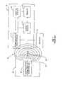
- FIG. 1is a schematic diagram of a wireless communication device in the prior art
- FIG. 2is a schematic diagram of a wireless communication device attached to a coin-cell battery for power and coupled to a slot on the battery to form a slot antenna;
- FIG. 3is a schematic diagram of a wireless communication device attached and grounded to a coin-cell battery for power and coupled to a slot on the battery to form a slot antenna;
- FIG. 4is a schematic diagram of a wireless communication device having a combined feed line and feed point to couple the wireless communication device to a slot and to a battery terminal for power;
- FIG. 5is a schematic diagram of a wireless communication device attached to a coin-cell battery for power and coupled to a slot in the battery at multiple points to form a slot antenna;
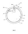
- FIG. 6is a schematic diagram of a wireless communication device placed across a slot formed by a battery seal to form a slot antenna
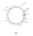
- FIG. 7is a schematic diagram of a wireless communication device placed across a slot formed by a battery seal to form a slot antenna with one feed point additionally extending to cross the slot at a second point;
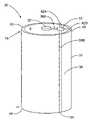
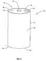
- FIG. 8is a schematic diagram of a wireless communication device attached to a cylindrical-shaped battery and coupled to a slot on the battery to form a slot antenna;
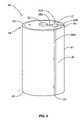
- FIG. 9is a schematic diagram of a wireless communication device attached to a cylindrical-shaped battery for power and coupled to a slot on the battery at multiple points to form a slot antenna;
- FIG. 10is a schematic diagram of a wireless communication device attached underneath a battery sleeve and coupled to a slot on the battery to form a slot antenna.
- the present inventionis directed to a device, system and method of using an energy source in an electronic device as a slot antenna.
- FIG. 1illustrates a typical wireless communication device and communication system in the prior art.
- the wireless communication device 10is capable of communicating information wirelessly and may include a control system 12 , a communication electronics 14 , a memory 16 , and an energy source 17 .
- the wireless communication device 10may be a radio-frequency identification device (RFID), but the present invention is not limited to any particular type of wireless communication device 10 .
- the communication electronics 14is coupled to an antenna 18 for wirelessly communicating information in radio-frequency signals.
- the communication electronics 14is capable of receiving a modulated radio-frequency signal through the antenna 18 and demodulating the signal into information passed to the control system 12 .
- the antenna 18may be internal or external to the wireless communication device 10 .
- the control system 12may be any type of circuitry or processor that receives and processes information received by the communication electronics 14 , such as a micro-controller or microprocessor.
- the wireless communication device 10may also contain memory 16 for storage of information. Such information may include identification, tracking and/or other information desired.
- the memory 16may be electronic memory, such as random access memory (RAM), read-only memory (ROM), flash memory, diode, etc., or the memory 16 may be mechanical memory, such as a switch, dip-switch, etc.
- the energy source 17may be any type of energy source to provide power to the components of the wireless communication device 10 , including, but not limited to, a battery, a capacitor, and a solar cell.
- Some wireless communication devices 10are termed “active” devices meaning that they receive and transmit data using an energy source coupled to the wireless communication device 10 .
- a wireless communication devicemay use a battery for power as described in U.S. Pat. No. 6,130,602 entitled “Radio frequency data communications device,” or may use other forms of energy and/or power, such as a capacitor as described in U.S. Pat. No. 5,833,603, entitled “Implantable biosensing transponder” Both of the preceding patents are incorporated herein by reference in their entirety.
- wireless communication devices 10are termed “passive” devices meaning that they do not actively transmit and therefore may not need their own energy source for power.
- One type of passive wireless communication device 10is known as a “transponder.”
- a transpondereffectively transmits information by reflecting back a received signal from an external communication device, such as an interrogation reader.
- An example of a transponderis disclosed in U.S. Pat. No. 5,347,280, entitled “Frequency diversity transponder arrangement,” incorporated herein by reference in its entirety.
- Another example of a transponderis described in co-pending patent application Ser. No. 09/678,271, entitled “Wireless Communication Device and Method,” incorporated herein by reference in its entirety.
- FIG. 1depicts communication between a wireless communication device 10 and an interrogation reader 20 .
- the interrogation reader 20includes an interrogation communication electronics 22 and an interrogation antenna 24 .
- the interrogation reader 20communicates with the wireless communication device 10 by emitting an electronic signal 26 modulated by the interrogation communication electronics 22 through the interrogation antenna 24 .
- the interrogation antenna 24may be any type of antenna that can radiate a signal 26 through a field 28 so that a reception device, such as a wireless communication device 10 , can receive such signal 26 through its own antenna 18 .
- the field 28may be electromagnetic, magnetic, or electric.
- the signal 26may be a message containing information and/or a specific request for the wireless communication device 10 to perform a task.
- the communication electronics 14When the antenna 18 is in the presence of the field 28 emitted by the interrogation reader 20 , the communication electronics 14 are energized by the energy in signal 26 , thereby energizing the wireless communication device 10 .
- the wireless communication device 10remains energized so long as the antenna 18 is in the field 28 of the interrogation reader 20 .
- the communication electronics 14demodulates the signal 26 and sends the message containing information and/or request to the control system 12 for appropriate actions. It is readily understood to one of ordinary skill in the art that there are many other types of wireless communications devices and communication techniques than those described herein, and the present invention is not limited to a particular type of wireless communication device, technique or method.
- the wireless communication device 10uses a gap or slot between battery terminals to form a slot antenna for wireless communication.
- FIGS. 2–10illustrate various configurations of slots in batteries to provide a slot antenna 18 .
- the wireless communication device 10may couple to a slot in the battery to form a slot antenna 18 . More information on slot antennas 18 and their operation is described in U.S. Pat. No. 4,975,711, entitled “Slot antenna device for portable radiophone,” and pending patent application Ser. No. 09/536,334, entitled “Remote Communication Using Slot Antenna,” both of which are incorporated herein by reference in their entirety.
- FIG. 2illustrates a wireless communication device 10 coupled to an annular slot 40 in a battery 30 to form a slot antenna 18 .
- the wireless communication device 10uses the battery 30 to provide power for transmissions and to power other components of the wireless communication device 10 , such as the control system 12 , communication electronics 14 , memory 16 , and/or other devices contained in the wireless communication device 10 .
- FIG. 2depicts a particular type of battery 30 known as a coin-cell battery.
- the battery 30may a rechargeable battery, including, but not limited to lithium, Nickel Cadnium (NiCd), Nickel Metal-Hydride (NiMH).
- the battery 30may also be non-rechargeable.
- the battery 30may be of any voltage rating. If the battery 30 is used as an energy source 17 in the wireless communication device 10 , the battery 30 must be of the proper voltage to provide power to the wireless communication device 10 and/or its components or an additional voltage-regulating device must be provided in the wireless communication device 10 . For example, an additional rectifier may be included to decrease the battery 30 voltage, or a transformer may be included to increase the battery 30 voltage.
- the battery 30has two terminals—a positive terminal 32 and a negative terminal 34 .
- the positive terminal 32 and the negative terminal 34are separated by a separator 36 .
- the separator 36is a dielectric material hat creates a voltage potential between the positive terminal 32 and the negative terminal 34 .
- the separator 36may be constructed out of a non-conductive material or may be constructed out of a conductive material that conducts energy at currents of a particular frequency.
- the battery 30may be a conductor at direct current (DC) or low frequency current, but may be non-conducting at higher frequency current.
- the separator 36also acts as a seal between the positive terminal 32 and the negative terminal 34 to prevent the positive terminal 32 and the negative terminal 34 from short-circuiting.
- the wireless communication device 10may be placed on the battery 30 , and may be either placed on one of the terminals 32 , 34 or across the slot 40 formed by the separator 36 between the terminals 32 , 34 .
- An adhesive(not shown) may be used to attach the wireless communication device 10 to the battery 30 .
- the adhesivemay either be conductive or non-conductive. If the wireless communication device 10 is attached directly to the surface of the battery 30 to provide a connection between the terminals 32 , 34 for power, a conductive adhesive may be used to facilitate a combined connection and adhesion.
- a non-conductive adhesivemay be also used to attach the wireless communication device 10 to the battery 30 . Examples of adhesives include tape, glue, and epoxy.
- the wireless communication device 10includes two feed lines 38 A, 38 B.
- a feed line 38is any conductive connection that allows the transfer of electricity.
- the feed lines 38 A, 38 Bconnect the wireless communication device 10 to the positive and negative terminals 32 , 34 to provide power to the wireless communication device 10 .
- the wireless communication device 10is additionally grounded to the battery 30 by a feed line 38 B connection to the negative terminal 34 .
- An, adhesive(not shown) may be used to attach the feed lines 38 A, 38 B firmly to the battery 30 .
- a conductive adhesive(not shown) may be used with the feed line 38 B since the feed line 38 B does not run across the positive terminal 32 on its connection path to the negative terminal 34 .
- the feed line 38 Bmay require a non-conductive adhesive 39 A on the portion of the feed line 38 B that runs across the negative terminal 38 B in order to prevent short-circuiting of the positive terminal 32 and the negative terminal 34 .
- a conductive adhesive 39 Bmay be used on the portion of the feed line 38 B that runs across the positive terminal 32 to attach the feed line 38 B to the positive terminal 32 .
- the wireless communication device 10uses the battery 30 to provide a slot antenna 18 .
- the battery 30has a slot 40 created by the separator 36 between the positive terminal 32 and the negative terminal 34 .
- the wireless communication device 10is coupled to the slot 40 using a single feed point 42 to form the slot antenna 18 .
- a feed point 42is any type conductive connection that allows the transfer of energy.
- Coupling the wireless communication device 10 to the slot 40 at or proximate to one location on the slot 40creates an antenna radiation pattern similar to a dipole antenna.
- the E and H fields of the slot antenna 18are reversed from the E and H fields of a dipole antenna (not shown).
- the exact radiation pattern of the slot antenna 18may be different depending on the operating frequency and impedance of the wireless communication device 10 and the geometry and other characteristics, including impedance of the battery 30 and the slot 40 .
- the feed point 42may be constructed out of any type of conductive materials, such as copper or aluminum. Additionally, the feed point 42 may be a conductive tab like that used in a patch antenna, such as described in pending patent application Ser. No. 09/678,271, previously referenced above. These feed points 42 may be three millimeters in width or less.
- the feed point 42may be attached to the battery 30 using an adhesive, such as those adhesives discussed above for the feed lines 38 .
- a non-conductive adhesive(not shown) is used for the portion of feed point 42 that runs across the negative terminal 34 of the battery 30 so that the feed point 42 does not form a conductive connection to the negative terminal 34 .
- FIG. 3illustrates another embodiment of a wireless communication device 10 that is coupled to a slot 40 to provide a dipole-like slot antenna 18 with a radiation pattern similar to the embodiment illustrated in FIG. 2 .
- the wireless communication device 10 in FIG. 3only has one feed line 38 A to couple the wireless communication device 10 to the positive terminal 32 for power.
- the feed line 38 Bmay be a conductive portion (not shown) provided on the wireless communication device 10 directly to the negative terminal 34 of the point of attachment of the wireless communication device 10 to the battery 30 .
- the wireless communication device 10may have a pin, if an IC chip, that is attached directly to the negative terminal 34 .
- FIG. 4illustrates another embodiment of the wireless communication device 10 where a feed point 42 that is used to couple the wireless communication device 10 to the slot 40 , is also be used as a feed line 38 to couple the wireless communication device 10 to the positive terminal 32 for power.
- the wireless communication device 10contains one feed line 38 and one feed point 42 .
- the feed point 42may be left as an open circuit or may be connected to the positive terminal 32 . If the feed point 42 is connected to the positive terminal 32 , the wireless communication device 10 can use this connection as a slot antenna 18 as well as a connection to the battery 30 for power. If the feed point 42 is connected to the positive terminal 32 for power, feed line 38 provides a connection between the wireless communication device 10 and the negative terminal 34 .
- FIG. 5illustrates another embodiment of a wireless communication device 10 coupled to slot 40 to provide a dipole-like antenna pattern.
- the wireless communication device 10is configured similar to the wireless communication device 10 illustrated in FIG. 2 ; however, two feed points 42 A, 42 B are used to couple the wireless communication device 10 to the slot 40 .
- Use of multiple feed points 42may be desirable to change the radiation pattern of the slot antenna 18 , and/or to change reception and/or transmission capability. Further, use of more than one feed point 42 may allow the slot antenna 18 and the wireless communication device 10 to operate at multiple frequencies.
- An example of a wireless communication device using multiple feed points in a slot antennais disclosed in U.S. Pat. No. 6,985,119, entitled “Multiple Feed Point Slot Antenna,” issued Jan. 10, 2006, by the assignee of this application, incorporated herein by reference in its entirety.
- FIG. 6illustrates another embodiment of a wireless communication device 10 that is coupled to a slot 40 on the battery 30 to provide a slot antenna 18 .
- the wireless communication device 10is placed across the slot 40 .
- Two feed points 42 A, 42 Bare used; one feed point 42 A is coupled to the positive terminal 32 and the other feed point 42 B is coupled to the negative terminal 34 . If the feed points 42 are non-conductive, the wireless communication device 10 capacitively couples to the slot 40 between the positive terminal 32 and the negative terminal 34 to form a slot antenna 18 .
- the wireless communication device 10may use such connection for both a connection to terminals 32 , 34 for power and connection to the slot 40 to provide a slot antenna 18 without need for a feed line 38 .
- FIG. 7illustrates another embodiment of a wireless communication device 10 coupled to a slot 40 on a battery 30 to provide a slot antenna 18 .
- the wireless communication device 10is coupled across the slot 40 like in FIG. 6 .
- the feed point 42 Bis coupled to the slot 40 at a different point than the feed point 42 A. This changes the effective length of the slot 40 so that the slot 40 resonates at a particular frequency of design and assists in matching the impedance of the slot 40 to the impedance of wireless communication device 10 for improved antenna 18 performance.
- the adhesive used for coupling the feed points 42 A, 42 B to the slot 40must be non-conductive in the region that the feed points 42 A, 42 B cross the slot 40 , or a short circuit at direct current will be placed across battery 30 . Therefore, the feed points 42 A, 42 B are capacatively coupled to the slot 40 .
- FIG. 8illustrates another embodiment of the present invention where a wireless communication device 10 is connected to a cylindrical-shaped battery 30 .
- the battery 30may be a commonly available, off-the-shelf battery, including sizes AA, AAA, C, and D.
- the battery 30contains a body 31 that is covered by a sleeve 33 to encapsulate the body 31 .
- the sleeve 33may be constructed out of a plastic or other encapsulating material and may be heat-shrinkable.
- the top of the body 31contains the positive terminal 32
- the bottom of the body 31contains the negative terminal 34 .
- the separator 36separates the positive terminal 32 from the negative terminal 34 , as previously discussed above.
- the wireless communication device 10is attached in the upper region of the battery 30 adjacent to the positive terminal 32 .
- the wireless communication device 10may be attached to the battery 30 using an adhesive (not shown), as previously discussed.
- a conductive adhesivemay be used if the wireless communication device 10 is connected directly to the positive terminal 32 without need for a feed line 38 .
- Feed linesare not used in this embodiment since the wireless communication device 10 does not use a battery 30 to provide power.
- the wireless communication device 10either has its own internal energy source or is a passive device.
- One feed point 42is used to couple the wireless communication device 10 to the slot 40 to provide a slot antenna 18 .
- FIG. 9illustrates a wireless communication device 10 attached to a battery 30 similar to the embodiment illustrated in FIG. 8 ; however, the wireless communication device 10 uses feed lines 38 A, 38 B to couple the wireless communication device 10 to the positive and negative terminals 32 , 34 respectively for power like that illustrated in FIG. 5 .
- Two feed points 42 A, 42 Bare also provided so that the wireless communication device 10 is coupled to the slot 40 at two points just as in the embodiment illustrated in FIG. 5 .
- the feed line 38 Bextends down the body 31 to the negative terminal 34 . Since the body 31 is constructed out of a non-conductive material, any type of adhesive (not shown) may be used to attach the feed line 38 B to the battery 30 . However, it is more desirable to use a non-conductive adhesive so that any devices or materials that come into contact with the body 31 are not grounded to the negative terminal 34 unwantingly. This embodiment could also be practiced in reverse whereby the wireless communication device 10 is attached to the lower portion of the battery 30 at the negative terminal 34 , and the feed line 38 A is extended upward to connect to the positive terminal 32 . Again, any type of adhesive may be used to attach the feed line 38 A to the body 31 , but a non-conductive adhesive is more desirable.
- FIG. 10illustrates a wireless communication device 10 attached underneath the sleeve 33 of a battery 30 as a convenient method of attachment.
- an adhesivemay not be required to secure the wireless communication device 10 to the battery 30 .
- the wireless communication device 10may be attached underneath the sleeve 33 during the manufacturing process of the battery 30 .
- a single feed point 42is coupled to the slot 40 to provide a slot antenna 18 .
- the wireless communication device 10is not coupled to the terminals 32 , 34 for power. However, the wireless communication device 10 may use feed lines (not shown) to couple the wireless communication device 10 to the terminals 32 , 34 for power if desired.
- the wireless communication device 10may also be placed totally internal to a battery 30 (not illustrated).
- the battery 30contains an electrolyte plate structure.
- a non-conductive void areamay be constructed between the battery 30 plates, and the wireless communication device 10 may be placed in this void.
- the wireless communication device 10may be connected to the positive and negative terminals 32 , 34 for power and/or to the slot 40 to provide a slot antenna 18 .
- the present inventionalso allows recharging of the energy source 17 illustrated in FIG. 1 if the wireless communication device 10 is coupled to terminals 32 , 34 .
- External radio-frequency signals received by the wireless communication device 10may contain energy. Since the wireless communication device 10 is capable of receiving energy from an external radio frequency signal through its antenna 18 , the wireless communication device 10 may recharge the battery 30 using such energy-bearing radio-frequency signal 26 rather than directly connecting the wireless communication device 10 to a power source. More information on recharging systems for energy sources is disclosed in co-pending Provisional Patent Application No. 60/375,247 entitled “Energy source recharging device and method,” filed on the same day as the present invention and incorporated herein by reference in its entirety, and attached hereto as an Appendix.
- the energy-bearing radio-frequency signal 26may be generated by an interrogation reader 20 located nearby the wireless communication device 10 , or by a remote radio-frequency transmitter.
- the wireless communication device 10uses the energy in the energy-bearing radio-frequency signal 26 to recharge the energy source 17 , which may be a battery 30 .
- the antenna 18receives the energy-bearing radio-frequency signal 26 that is used to recharge the energy source 17 , and the antenna 18 may be any type of antenna, including a pole antenna or a slot antenna.
- couple, coupled, or couplingis defined as either a direct connection or a reactive coupling.
- Reactive couplingis defined as either capacitive or inductive coupling.
Landscapes
- Engineering & Computer Science (AREA)
- Computer Networks & Wireless Communication (AREA)
- Microelectronics & Electronic Packaging (AREA)
- Physics & Mathematics (AREA)
- General Physics & Mathematics (AREA)
- Theoretical Computer Science (AREA)
- Computer Hardware Design (AREA)
- Support Of Aerials (AREA)
- Details Of Aerials (AREA)
- Mobile Radio Communication Systems (AREA)
- Variable-Direction Aerials And Aerial Arrays (AREA)
- Near-Field Transmission Systems (AREA)
- Radar Systems Or Details Thereof (AREA)
- Waveguide Aerials (AREA)
Abstract
Description
Claims (35)
Priority Applications (4)
| Application Number | Priority Date | Filing Date | Title |
|---|---|---|---|
| US10/422,609US7123204B2 (en) | 2002-04-24 | 2003-04-24 | Energy source communication employing slot antenna |
| US11/515,154US7372418B2 (en) | 2002-04-24 | 2006-08-31 | Energy source communication employing slot antenna |
| US11/751,529US7414589B2 (en) | 2002-04-24 | 2007-05-21 | Energy source communication employing slot antenna |
| US12/172,196US7755556B2 (en) | 2002-04-24 | 2008-07-11 | Energy source communication employing slot antenna |
Applications Claiming Priority (2)
| Application Number | Priority Date | Filing Date | Title |
|---|---|---|---|
| US37525802P | 2002-04-24 | 2002-04-24 | |
| US10/422,609US7123204B2 (en) | 2002-04-24 | 2003-04-24 | Energy source communication employing slot antenna |
Related Child Applications (1)
| Application Number | Title | Priority Date | Filing Date |
|---|---|---|---|
| US11/515,154ContinuationUS7372418B2 (en) | 2002-04-24 | 2006-08-31 | Energy source communication employing slot antenna |
Publications (2)
| Publication Number | Publication Date |
|---|---|
| US20040036657A1 US20040036657A1 (en) | 2004-02-26 |
| US7123204B2true US7123204B2 (en) | 2006-10-17 |
Family
ID=29270621
Family Applications (4)
| Application Number | Title | Priority Date | Filing Date |
|---|---|---|---|
| US10/422,609Expired - LifetimeUS7123204B2 (en) | 2002-04-24 | 2003-04-24 | Energy source communication employing slot antenna |
| US11/515,154Expired - LifetimeUS7372418B2 (en) | 2002-04-24 | 2006-08-31 | Energy source communication employing slot antenna |
| US11/751,529Expired - LifetimeUS7414589B2 (en) | 2002-04-24 | 2007-05-21 | Energy source communication employing slot antenna |
| US12/172,196Expired - Fee RelatedUS7755556B2 (en) | 2002-04-24 | 2008-07-11 | Energy source communication employing slot antenna |
Family Applications After (3)
| Application Number | Title | Priority Date | Filing Date |
|---|---|---|---|
| US11/515,154Expired - LifetimeUS7372418B2 (en) | 2002-04-24 | 2006-08-31 | Energy source communication employing slot antenna |
| US11/751,529Expired - LifetimeUS7414589B2 (en) | 2002-04-24 | 2007-05-21 | Energy source communication employing slot antenna |
| US12/172,196Expired - Fee RelatedUS7755556B2 (en) | 2002-04-24 | 2008-07-11 | Energy source communication employing slot antenna |
Country Status (7)
| Country | Link |
|---|---|
| US (4) | US7123204B2 (en) |
| EP (1) | EP1500167B1 (en) |
| AT (1) | ATE406673T1 (en) |
| AU (1) | AU2003233007A1 (en) |
| CA (1) | CA2519425A1 (en) |
| DE (1) | DE60323221D1 (en) |
| WO (1) | WO2003092116A2 (en) |
Cited By (11)
| Publication number | Priority date | Publication date | Assignee | Title |
|---|---|---|---|---|
| US20060250314A1 (en)* | 2000-03-25 | 2006-11-09 | Mineral Lassen Llc | Multiple feed point slot antenna |
| US20070285325A1 (en)* | 2006-06-07 | 2007-12-13 | St Clair John Quincy | Chi energy amplifier |
| US7372418B2 (en) | 2002-04-24 | 2008-05-13 | Mineral Lassen Llc | Energy source communication employing slot antenna |
| US20080174436A1 (en)* | 2007-01-22 | 2008-07-24 | Jeremy Landt | Light Activated RFID Tag |
| US20090027228A1 (en)* | 2007-07-24 | 2009-01-29 | Tricoukes Nicole D | System and Method for Wirelessly Communicating Battery Status |
| US20090079568A1 (en)* | 2007-09-26 | 2009-03-26 | Forster Ian J | Rfid interposer with impedance matching |
| US20090140860A1 (en)* | 2007-12-03 | 2009-06-04 | Forster Ian J | Dual use rfid/eas device |
| US20090146785A1 (en)* | 2007-12-11 | 2009-06-11 | Forster Ian J | Rfid device with multiple passive operation modes |
| US20090146783A1 (en)* | 2007-12-05 | 2009-06-11 | Forster Ian J | Rfid system with distributed read structure |
| US7768407B2 (en) | 2007-06-22 | 2010-08-03 | Avery Dennison Corporation | Foldable RFID device interposer and method |
| US8583063B1 (en) | 2010-04-01 | 2013-11-12 | Sprint Communications Company L.P. | Antenna configuration selection by a wireless communication device |
Families Citing this family (193)
| Publication number | Priority date | Publication date | Assignee | Title |
|---|---|---|---|---|
| JP3974538B2 (en) | 2003-02-20 | 2007-09-12 | 株式会社日立製作所 | Information processing system |
| JP4165747B2 (en) | 2003-03-20 | 2008-10-15 | 株式会社日立製作所 | Storage system, control device, and control device program |
| US7545272B2 (en) | 2005-02-08 | 2009-06-09 | Therasense, Inc. | RF tag on test strips, test strip vials and boxes |
| US7501947B2 (en)* | 2005-05-04 | 2009-03-10 | Tc License, Ltd. | RFID tag with small aperture antenna |
| FR2903216A1 (en)* | 2006-06-28 | 2008-01-04 | Thomson Licensing Sa | IMPROVING DATA MEDIA SUCH AS OPTICAL MEDIA |
| US7564356B1 (en) | 2006-10-06 | 2009-07-21 | Tc License, Ltd. | Interdigit AC coupling for RFID tags |
| JP2009088816A (en)* | 2007-09-28 | 2009-04-23 | Rohm Co Ltd | Information communication terminal, wireless communication device, and wireless communication network |
| FR2923324B1 (en)* | 2007-11-05 | 2010-09-10 | Commissariat Energie Atomique | WIDEBAND INDUCTIVE ANTENNA FOR CONTACTLESS COMMUNICATION SYSTEMS |
| TW200922073A (en)* | 2007-11-08 | 2009-05-16 | Amic Technology Corp | Charger system capable of enhancing convenience |
| US20090256766A1 (en)* | 2008-04-09 | 2009-10-15 | Bury Sp Z O.O. | Mobile phone antenna integrated with battery |
| WO2011154372A1 (en) | 2010-06-08 | 2011-12-15 | Roche Diagnostics Gmbh | Analyte sensor having a slot antenna |
| US9647318B2 (en) | 2012-05-30 | 2017-05-09 | Echostar Technologies L.L.C. | Modular antenna system |
| US10063106B2 (en) | 2014-05-23 | 2018-08-28 | Energous Corporation | System and method for a self-system analysis in a wireless power transmission network |
| US9787103B1 (en) | 2013-08-06 | 2017-10-10 | Energous Corporation | Systems and methods for wirelessly delivering power to electronic devices that are unable to communicate with a transmitter |
| US10193396B1 (en) | 2014-05-07 | 2019-01-29 | Energous Corporation | Cluster management of transmitters in a wireless power transmission system |
| US9843213B2 (en) | 2013-08-06 | 2017-12-12 | Energous Corporation | Social power sharing for mobile devices based on pocket-forming |
| US9859797B1 (en) | 2014-05-07 | 2018-01-02 | Energous Corporation | Synchronous rectifier design for wireless power receiver |
| US10211674B1 (en) | 2013-06-12 | 2019-02-19 | Energous Corporation | Wireless charging using selected reflectors |
| US9991741B1 (en) | 2014-07-14 | 2018-06-05 | Energous Corporation | System for tracking and reporting status and usage information in a wireless power management system |
| US9853458B1 (en) | 2014-05-07 | 2017-12-26 | Energous Corporation | Systems and methods for device and power receiver pairing |
| US9143000B2 (en) | 2012-07-06 | 2015-09-22 | Energous Corporation | Portable wireless charging pad |
| US9793758B2 (en) | 2014-05-23 | 2017-10-17 | Energous Corporation | Enhanced transmitter using frequency control for wireless power transmission |
| US9838083B2 (en) | 2014-07-21 | 2017-12-05 | Energous Corporation | Systems and methods for communication with remote management systems |
| US9806564B2 (en) | 2014-05-07 | 2017-10-31 | Energous Corporation | Integrated rectifier and boost converter for wireless power transmission |
| US10291055B1 (en) | 2014-12-29 | 2019-05-14 | Energous Corporation | Systems and methods for controlling far-field wireless power transmission based on battery power levels of a receiving device |
| US10256657B2 (en) | 2015-12-24 | 2019-04-09 | Energous Corporation | Antenna having coaxial structure for near field wireless power charging |
| US10992187B2 (en) | 2012-07-06 | 2021-04-27 | Energous Corporation | System and methods of using electromagnetic waves to wirelessly deliver power to electronic devices |
| US10199849B1 (en) | 2014-08-21 | 2019-02-05 | Energous Corporation | Method for automatically testing the operational status of a wireless power receiver in a wireless power transmission system |
| US9912199B2 (en) | 2012-07-06 | 2018-03-06 | Energous Corporation | Receivers for wireless power transmission |
| US9847677B1 (en) | 2013-10-10 | 2017-12-19 | Energous Corporation | Wireless charging and powering of healthcare gadgets and sensors |
| US9954374B1 (en) | 2014-05-23 | 2018-04-24 | Energous Corporation | System and method for self-system analysis for detecting a fault in a wireless power transmission Network |
| US9923386B1 (en) | 2012-07-06 | 2018-03-20 | Energous Corporation | Systems and methods for wireless power transmission by modifying a number of antenna elements used to transmit power waves to a receiver |
| US10199835B2 (en) | 2015-12-29 | 2019-02-05 | Energous Corporation | Radar motion detection using stepped frequency in wireless power transmission system |
| US9899873B2 (en) | 2014-05-23 | 2018-02-20 | Energous Corporation | System and method for generating a power receiver identifier in a wireless power network |
| US10263432B1 (en) | 2013-06-25 | 2019-04-16 | Energous Corporation | Multi-mode transmitter with an antenna array for delivering wireless power and providing Wi-Fi access |
| US9973021B2 (en) | 2012-07-06 | 2018-05-15 | Energous Corporation | Receivers for wireless power transmission |
| US10224758B2 (en) | 2013-05-10 | 2019-03-05 | Energous Corporation | Wireless powering of electronic devices with selective delivery range |
| US9438045B1 (en) | 2013-05-10 | 2016-09-06 | Energous Corporation | Methods and systems for maximum power point transfer in receivers |
| US10038337B1 (en) | 2013-09-16 | 2018-07-31 | Energous Corporation | Wireless power supply for rescue devices |
| US10008889B2 (en) | 2014-08-21 | 2018-06-26 | Energous Corporation | Method for automatically testing the operational status of a wireless power receiver in a wireless power transmission system |
| US20140008993A1 (en) | 2012-07-06 | 2014-01-09 | DvineWave Inc. | Methodology for pocket-forming |
| US9124125B2 (en) | 2013-05-10 | 2015-09-01 | Energous Corporation | Wireless power transmission with selective range |
| US10124754B1 (en) | 2013-07-19 | 2018-11-13 | Energous Corporation | Wireless charging and powering of electronic sensors in a vehicle |
| US10075008B1 (en) | 2014-07-14 | 2018-09-11 | Energous Corporation | Systems and methods for manually adjusting when receiving electronic devices are scheduled to receive wirelessly delivered power from a wireless power transmitter in a wireless power network |
| US9876379B1 (en) | 2013-07-11 | 2018-01-23 | Energous Corporation | Wireless charging and powering of electronic devices in a vehicle |
| US9948135B2 (en) | 2015-09-22 | 2018-04-17 | Energous Corporation | Systems and methods for identifying sensitive objects in a wireless charging transmission field |
| US9843201B1 (en) | 2012-07-06 | 2017-12-12 | Energous Corporation | Wireless power transmitter that selects antenna sets for transmitting wireless power to a receiver based on location of the receiver, and methods of use thereof |
| US9867062B1 (en) | 2014-07-21 | 2018-01-09 | Energous Corporation | System and methods for using a remote server to authorize a receiving device that has requested wireless power and to determine whether another receiving device should request wireless power in a wireless power transmission system |
| US9887584B1 (en) | 2014-08-21 | 2018-02-06 | Energous Corporation | Systems and methods for a configuration web service to provide configuration of a wireless power transmitter within a wireless power transmission system |
| US9871398B1 (en) | 2013-07-01 | 2018-01-16 | Energous Corporation | Hybrid charging method for wireless power transmission based on pocket-forming |
| US9859757B1 (en) | 2013-07-25 | 2018-01-02 | Energous Corporation | Antenna tile arrangements in electronic device enclosures |
| US9939864B1 (en) | 2014-08-21 | 2018-04-10 | Energous Corporation | System and method to control a wireless power transmission system by configuration of wireless power transmission control parameters |
| US10186913B2 (en) | 2012-07-06 | 2019-01-22 | Energous Corporation | System and methods for pocket-forming based on constructive and destructive interferences to power one or more wireless power receivers using a wireless power transmitter including a plurality of antennas |
| US11502551B2 (en) | 2012-07-06 | 2022-11-15 | Energous Corporation | Wirelessly charging multiple wireless-power receivers using different subsets of an antenna array to focus energy at different locations |
| US10270261B2 (en) | 2015-09-16 | 2019-04-23 | Energous Corporation | Systems and methods of object detection in wireless power charging systems |
| US10205239B1 (en) | 2014-05-07 | 2019-02-12 | Energous Corporation | Compact PIFA antenna |
| US10206185B2 (en) | 2013-05-10 | 2019-02-12 | Energous Corporation | System and methods for wireless power transmission to an electronic device in accordance with user-defined restrictions |
| US9831718B2 (en) | 2013-07-25 | 2017-11-28 | Energous Corporation | TV with integrated wireless power transmitter |
| US9824815B2 (en) | 2013-05-10 | 2017-11-21 | Energous Corporation | Wireless charging and powering of healthcare gadgets and sensors |
| US10141768B2 (en) | 2013-06-03 | 2018-11-27 | Energous Corporation | Systems and methods for maximizing wireless power transfer efficiency by instructing a user to change a receiver device's position |
| US9966765B1 (en) | 2013-06-25 | 2018-05-08 | Energous Corporation | Multi-mode transmitter |
| US10312715B2 (en) | 2015-09-16 | 2019-06-04 | Energous Corporation | Systems and methods for wireless power charging |
| US9825674B1 (en) | 2014-05-23 | 2017-11-21 | Energous Corporation | Enhanced transmitter that selects configurations of antenna elements for performing wireless power transmission and receiving functions |
| US10103582B2 (en) | 2012-07-06 | 2018-10-16 | Energous Corporation | Transmitters for wireless power transmission |
| US10381880B2 (en) | 2014-07-21 | 2019-08-13 | Energous Corporation | Integrated antenna structure arrays for wireless power transmission |
| US10090886B1 (en) | 2014-07-14 | 2018-10-02 | Energous Corporation | System and method for enabling automatic charging schedules in a wireless power network to one or more devices |
| US10291066B1 (en) | 2014-05-07 | 2019-05-14 | Energous Corporation | Power transmission control systems and methods |
| US9891669B2 (en) | 2014-08-21 | 2018-02-13 | Energous Corporation | Systems and methods for a configuration web service to provide configuration of a wireless power transmitter within a wireless power transmission system |
| US9899861B1 (en) | 2013-10-10 | 2018-02-20 | Energous Corporation | Wireless charging methods and systems for game controllers, based on pocket-forming |
| US9876394B1 (en) | 2014-05-07 | 2018-01-23 | Energous Corporation | Boost-charger-boost system for enhanced power delivery |
| US9847679B2 (en) | 2014-05-07 | 2017-12-19 | Energous Corporation | System and method for controlling communication between wireless power transmitter managers |
| US10148097B1 (en) | 2013-11-08 | 2018-12-04 | Energous Corporation | Systems and methods for using a predetermined number of communication channels of a wireless power transmitter to communicate with different wireless power receivers |
| US10050462B1 (en) | 2013-08-06 | 2018-08-14 | Energous Corporation | Social power sharing for mobile devices based on pocket-forming |
| US10128693B2 (en) | 2014-07-14 | 2018-11-13 | Energous Corporation | System and method for providing health safety in a wireless power transmission system |
| US9882430B1 (en) | 2014-05-07 | 2018-01-30 | Energous Corporation | Cluster management of transmitters in a wireless power transmission system |
| US9853692B1 (en) | 2014-05-23 | 2017-12-26 | Energous Corporation | Systems and methods for wireless power transmission |
| US10230266B1 (en) | 2014-02-06 | 2019-03-12 | Energous Corporation | Wireless power receivers that communicate status data indicating wireless power transmission effectiveness with a transmitter using a built-in communications component of a mobile device, and methods of use thereof |
| US10992185B2 (en) | 2012-07-06 | 2021-04-27 | Energous Corporation | Systems and methods of using electromagnetic waves to wirelessly deliver power to game controllers |
| US9812890B1 (en) | 2013-07-11 | 2017-11-07 | Energous Corporation | Portable wireless charging pad |
| US12057715B2 (en) | 2012-07-06 | 2024-08-06 | Energous Corporation | Systems and methods of wirelessly delivering power to a wireless-power receiver device in response to a change of orientation of the wireless-power receiver device |
| US10223717B1 (en) | 2014-05-23 | 2019-03-05 | Energous Corporation | Systems and methods for payment-based authorization of wireless power transmission service |
| US9887739B2 (en) | 2012-07-06 | 2018-02-06 | Energous Corporation | Systems and methods for wireless power transmission by comparing voltage levels associated with power waves transmitted by antennas of a plurality of antennas of a transmitter to determine appropriate phase adjustments for the power waves |
| US10224982B1 (en) | 2013-07-11 | 2019-03-05 | Energous Corporation | Wireless power transmitters for transmitting wireless power and tracking whether wireless power receivers are within authorized locations |
| US10439448B2 (en) | 2014-08-21 | 2019-10-08 | Energous Corporation | Systems and methods for automatically testing the communication between wireless power transmitter and wireless power receiver |
| US9941754B2 (en) | 2012-07-06 | 2018-04-10 | Energous Corporation | Wireless power transmission with selective range |
| US9859756B2 (en) | 2012-07-06 | 2018-01-02 | Energous Corporation | Transmittersand methods for adjusting wireless power transmission based on information from receivers |
| US9252628B2 (en) | 2013-05-10 | 2016-02-02 | Energous Corporation | Laptop computer as a transmitter for wireless charging |
| US9941747B2 (en) | 2014-07-14 | 2018-04-10 | Energous Corporation | System and method for manually selecting and deselecting devices to charge in a wireless power network |
| US10243414B1 (en) | 2014-05-07 | 2019-03-26 | Energous Corporation | Wearable device with wireless power and payload receiver |
| US10211680B2 (en) | 2013-07-19 | 2019-02-19 | Energous Corporation | Method for 3 dimensional pocket-forming |
| US10090699B1 (en) | 2013-11-01 | 2018-10-02 | Energous Corporation | Wireless powered house |
| US10128699B2 (en) | 2014-07-14 | 2018-11-13 | Energous Corporation | Systems and methods of providing wireless power using receiver device sensor inputs |
| US20150326070A1 (en) | 2014-05-07 | 2015-11-12 | Energous Corporation | Methods and Systems for Maximum Power Point Transfer in Receivers |
| US9893554B2 (en) | 2014-07-14 | 2018-02-13 | Energous Corporation | System and method for providing health safety in a wireless power transmission system |
| US10211682B2 (en) | 2014-05-07 | 2019-02-19 | Energous Corporation | Systems and methods for controlling operation of a transmitter of a wireless power network based on user instructions received from an authenticated computing device powered or charged by a receiver of the wireless power network |
| US9882427B2 (en) | 2013-05-10 | 2018-01-30 | Energous Corporation | Wireless power delivery using a base station to control operations of a plurality of wireless power transmitters |
| US10218227B2 (en) | 2014-05-07 | 2019-02-26 | Energous Corporation | Compact PIFA antenna |
| US10965164B2 (en) | 2012-07-06 | 2021-03-30 | Energous Corporation | Systems and methods of wirelessly delivering power to a receiver device |
| US9900057B2 (en) | 2012-07-06 | 2018-02-20 | Energous Corporation | Systems and methods for assigning groups of antenas of a wireless power transmitter to different wireless power receivers, and determining effective phases to use for wirelessly transmitting power using the assigned groups of antennas |
| US9368020B1 (en) | 2013-05-10 | 2016-06-14 | Energous Corporation | Off-premises alert system and method for wireless power receivers in a wireless power network |
| US9893555B1 (en) | 2013-10-10 | 2018-02-13 | Energous Corporation | Wireless charging of tools using a toolbox transmitter |
| US9906065B2 (en) | 2012-07-06 | 2018-02-27 | Energous Corporation | Systems and methods of transmitting power transmission waves based on signals received at first and second subsets of a transmitter's antenna array |
| US9941707B1 (en) | 2013-07-19 | 2018-04-10 | Energous Corporation | Home base station for multiple room coverage with multiple transmitters |
| US10141791B2 (en) | 2014-05-07 | 2018-11-27 | Energous Corporation | Systems and methods for controlling communications during wireless transmission of power using application programming interfaces |
| US9876648B2 (en) | 2014-08-21 | 2018-01-23 | Energous Corporation | System and method to control a wireless power transmission system by configuration of wireless power transmission control parameters |
| US10063064B1 (en) | 2014-05-23 | 2018-08-28 | Energous Corporation | System and method for generating a power receiver identifier in a wireless power network |
| US9893768B2 (en) | 2012-07-06 | 2018-02-13 | Energous Corporation | Methodology for multiple pocket-forming |
| US10063105B2 (en) | 2013-07-11 | 2018-08-28 | Energous Corporation | Proximity transmitters for wireless power charging systems |
| USD746798S1 (en)* | 2012-12-31 | 2016-01-05 | Echostar Technologies L.L.C. | Indoor antenna |
| US9819230B2 (en) | 2014-05-07 | 2017-11-14 | Energous Corporation | Enhanced receiver for wireless power transmission |
| US9866279B2 (en) | 2013-05-10 | 2018-01-09 | Energous Corporation | Systems and methods for selecting which power transmitter should deliver wireless power to a receiving device in a wireless power delivery network |
| US9538382B2 (en) | 2013-05-10 | 2017-01-03 | Energous Corporation | System and method for smart registration of wireless power receivers in a wireless power network |
| US9537357B2 (en) | 2013-05-10 | 2017-01-03 | Energous Corporation | Wireless sound charging methods and systems for game controllers, based on pocket-forming |
| US9419443B2 (en) | 2013-05-10 | 2016-08-16 | Energous Corporation | Transducer sound arrangement for pocket-forming |
| US9478850B2 (en) | 2013-05-23 | 2016-10-25 | Duracell U.S. Operations, Inc. | Omni-directional antenna for a cylindrical body |
| US10103552B1 (en) | 2013-06-03 | 2018-10-16 | Energous Corporation | Protocols for authenticated wireless power transmission |
| US10003211B1 (en) | 2013-06-17 | 2018-06-19 | Energous Corporation | Battery life of portable electronic devices |
| US10021523B2 (en) | 2013-07-11 | 2018-07-10 | Energous Corporation | Proximity transmitters for wireless power charging systems |
| US9979440B1 (en) | 2013-07-25 | 2018-05-22 | Energous Corporation | Antenna tile arrangements configured to operate as one functional unit |
| US9935482B1 (en) | 2014-02-06 | 2018-04-03 | Energous Corporation | Wireless power transmitters that transmit at determined times based on power availability and consumption at a receiving mobile device |
| US10075017B2 (en) | 2014-02-06 | 2018-09-11 | Energous Corporation | External or internal wireless power receiver with spaced-apart antenna elements for charging or powering mobile devices using wirelessly delivered power |
| US10158257B2 (en) | 2014-05-01 | 2018-12-18 | Energous Corporation | System and methods for using sound waves to wirelessly deliver power to electronic devices |
| US9966784B2 (en) | 2014-06-03 | 2018-05-08 | Energous Corporation | Systems and methods for extending battery life of portable electronic devices charged by sound |
| US10170917B1 (en) | 2014-05-07 | 2019-01-01 | Energous Corporation | Systems and methods for managing and controlling a wireless power network by establishing time intervals during which receivers communicate with a transmitter |
| US10153645B1 (en) | 2014-05-07 | 2018-12-11 | Energous Corporation | Systems and methods for designating a master power transmitter in a cluster of wireless power transmitters |
| US10153653B1 (en) | 2014-05-07 | 2018-12-11 | Energous Corporation | Systems and methods for using application programming interfaces to control communications between a transmitter and a receiver |
| US9800172B1 (en) | 2014-05-07 | 2017-10-24 | Energous Corporation | Integrated rectifier and boost converter for boosting voltage received from wireless power transmission waves |
| US9973008B1 (en) | 2014-05-07 | 2018-05-15 | Energous Corporation | Wireless power receiver with boost converters directly coupled to a storage element |
| US9876536B1 (en) | 2014-05-23 | 2018-01-23 | Energous Corporation | Systems and methods for assigning groups of antennas to transmit wireless power to different wireless power receivers |
| US10068703B1 (en) | 2014-07-21 | 2018-09-04 | Energous Corporation | Integrated miniature PIFA with artificial magnetic conductor metamaterials |
| US10116143B1 (en) | 2014-07-21 | 2018-10-30 | Energous Corporation | Integrated antenna arrays for wireless power transmission |
| US9871301B2 (en) | 2014-07-21 | 2018-01-16 | Energous Corporation | Integrated miniature PIFA with artificial magnetic conductor metamaterials |
| US9917477B1 (en) | 2014-08-21 | 2018-03-13 | Energous Corporation | Systems and methods for automatically testing the communication between power transmitter and wireless receiver |
| US9965009B1 (en) | 2014-08-21 | 2018-05-08 | Energous Corporation | Systems and methods for assigning a power receiver to individual power transmitters based on location of the power receiver |
| US10243784B2 (en) | 2014-11-20 | 2019-03-26 | At&T Intellectual Property I, L.P. | System for generating topology information and methods thereof |
| US10122415B2 (en) | 2014-12-27 | 2018-11-06 | Energous Corporation | Systems and methods for assigning a set of antennas of a wireless power transmitter to a wireless power receiver based on a location of the wireless power receiver |
| US9893535B2 (en) | 2015-02-13 | 2018-02-13 | Energous Corporation | Systems and methods for determining optimal charging positions to maximize efficiency of power received from wirelessly delivered sound wave energy |
| US9906275B2 (en) | 2015-09-15 | 2018-02-27 | Energous Corporation | Identifying receivers in a wireless charging transmission field |
| US12283828B2 (en) | 2015-09-15 | 2025-04-22 | Energous Corporation | Receiver devices configured to determine location within a transmission field |
| US10523033B2 (en) | 2015-09-15 | 2019-12-31 | Energous Corporation | Receiver devices configured to determine location within a transmission field |
| US10778041B2 (en) | 2015-09-16 | 2020-09-15 | Energous Corporation | Systems and methods for generating power waves in a wireless power transmission system |
| US9871387B1 (en) | 2015-09-16 | 2018-01-16 | Energous Corporation | Systems and methods of object detection using one or more video cameras in wireless power charging systems |
| US10211685B2 (en) | 2015-09-16 | 2019-02-19 | Energous Corporation | Systems and methods for real or near real time wireless communications between a wireless power transmitter and a wireless power receiver |
| US10008875B1 (en) | 2015-09-16 | 2018-06-26 | Energous Corporation | Wireless power transmitter configured to transmit power waves to a predicted location of a moving wireless power receiver |
| US11710321B2 (en) | 2015-09-16 | 2023-07-25 | Energous Corporation | Systems and methods of object detection in wireless power charging systems |
| US10158259B1 (en) | 2015-09-16 | 2018-12-18 | Energous Corporation | Systems and methods for identifying receivers in a transmission field by transmitting exploratory power waves towards different segments of a transmission field |
| US9941752B2 (en) | 2015-09-16 | 2018-04-10 | Energous Corporation | Systems and methods of object detection in wireless power charging systems |
| US9893538B1 (en) | 2015-09-16 | 2018-02-13 | Energous Corporation | Systems and methods of object detection in wireless power charging systems |
| US10199850B2 (en) | 2015-09-16 | 2019-02-05 | Energous Corporation | Systems and methods for wirelessly transmitting power from a transmitter to a receiver by determining refined locations of the receiver in a segmented transmission field associated with the transmitter |
| US10186893B2 (en) | 2015-09-16 | 2019-01-22 | Energous Corporation | Systems and methods for real time or near real time wireless communications between a wireless power transmitter and a wireless power receiver |
| US10135295B2 (en) | 2015-09-22 | 2018-11-20 | Energous Corporation | Systems and methods for nullifying energy levels for wireless power transmission waves |
| US10050470B1 (en) | 2015-09-22 | 2018-08-14 | Energous Corporation | Wireless power transmission device having antennas oriented in three dimensions |
| US10033222B1 (en) | 2015-09-22 | 2018-07-24 | Energous Corporation | Systems and methods for determining and generating a waveform for wireless power transmission waves |
| US10128686B1 (en) | 2015-09-22 | 2018-11-13 | Energous Corporation | Systems and methods for identifying receiver locations using sensor technologies |
| US10020678B1 (en) | 2015-09-22 | 2018-07-10 | Energous Corporation | Systems and methods for selecting antennas to generate and transmit power transmission waves |
| US10153660B1 (en) | 2015-09-22 | 2018-12-11 | Energous Corporation | Systems and methods for preconfiguring sensor data for wireless charging systems |
| US10135294B1 (en) | 2015-09-22 | 2018-11-20 | Energous Corporation | Systems and methods for preconfiguring transmission devices for power wave transmissions based on location data of one or more receivers |
| US10027168B2 (en) | 2015-09-22 | 2018-07-17 | Energous Corporation | Systems and methods for generating and transmitting wireless power transmission waves using antennas having a spacing that is selected by the transmitter |
| US10734717B2 (en) | 2015-10-13 | 2020-08-04 | Energous Corporation | 3D ceramic mold antenna |
| US10333332B1 (en) | 2015-10-13 | 2019-06-25 | Energous Corporation | Cross-polarized dipole antenna |
| US9899744B1 (en) | 2015-10-28 | 2018-02-20 | Energous Corporation | Antenna for wireless charging systems |
| US9853485B2 (en) | 2015-10-28 | 2017-12-26 | Energous Corporation | Antenna for wireless charging systems |
| US10027180B1 (en) | 2015-11-02 | 2018-07-17 | Energous Corporation | 3D triple linear antenna that acts as heat sink |
| US10063108B1 (en) | 2015-11-02 | 2018-08-28 | Energous Corporation | Stamped three-dimensional antenna |
| US10135112B1 (en) | 2015-11-02 | 2018-11-20 | Energous Corporation | 3D antenna mount |
| US11863001B2 (en) | 2015-12-24 | 2024-01-02 | Energous Corporation | Near-field antenna for wireless power transmission with antenna elements that follow meandering patterns |
| US10256677B2 (en) | 2016-12-12 | 2019-04-09 | Energous Corporation | Near-field RF charging pad with adaptive loading to efficiently charge an electronic device at any position on the pad |
| US10320446B2 (en) | 2015-12-24 | 2019-06-11 | Energous Corporation | Miniaturized highly-efficient designs for near-field power transfer system |
| US10116162B2 (en) | 2015-12-24 | 2018-10-30 | Energous Corporation | Near field transmitters with harmonic filters for wireless power charging |
| US10079515B2 (en) | 2016-12-12 | 2018-09-18 | Energous Corporation | Near-field RF charging pad with multi-band antenna element with adaptive loading to efficiently charge an electronic device at any position on the pad |
| US10038332B1 (en) | 2015-12-24 | 2018-07-31 | Energous Corporation | Systems and methods of wireless power charging through multiple receiving devices |
| US10027159B2 (en) | 2015-12-24 | 2018-07-17 | Energous Corporation | Antenna for transmitting wireless power signals |
| US10008886B2 (en) | 2015-12-29 | 2018-06-26 | Energous Corporation | Modular antennas with heat sinks in wireless power transmission systems |
| US10608293B2 (en) | 2016-11-01 | 2020-03-31 | Duracell U.S. Operations, Inc. | Dual sided reusable battery indicator |
| US10923954B2 (en) | 2016-11-03 | 2021-02-16 | Energous Corporation | Wireless power receiver with a synchronous rectifier |
| KR102185600B1 (en) | 2016-12-12 | 2020-12-03 | 에너저스 코포레이션 | A method of selectively activating antenna zones of a near field charging pad to maximize transmitted wireless power |
| US10680319B2 (en) | 2017-01-06 | 2020-06-09 | Energous Corporation | Devices and methods for reducing mutual coupling effects in wireless power transmission systems |
| US10439442B2 (en) | 2017-01-24 | 2019-10-08 | Energous Corporation | Microstrip antennas for wireless power transmitters |
| US10389161B2 (en) | 2017-03-15 | 2019-08-20 | Energous Corporation | Surface mount dielectric antennas for wireless power transmitters |
| US11011942B2 (en) | 2017-03-30 | 2021-05-18 | Energous Corporation | Flat antennas having two or more resonant frequencies for use in wireless power transmission systems |
| US10511097B2 (en) | 2017-05-12 | 2019-12-17 | Energous Corporation | Near-field antennas for accumulating energy at a near-field distance with minimal far-field gain |
| US12074452B2 (en) | 2017-05-16 | 2024-08-27 | Wireless Electrical Grid Lan, Wigl Inc. | Networked wireless charging system |
| US11462949B2 (en) | 2017-05-16 | 2022-10-04 | Wireless electrical Grid LAN, WiGL Inc | Wireless charging method and system |
| US12074460B2 (en) | 2017-05-16 | 2024-08-27 | Wireless Electrical Grid Lan, Wigl Inc. | Rechargeable wireless power bank and method of using |
| US10848853B2 (en) | 2017-06-23 | 2020-11-24 | Energous Corporation | Systems, methods, and devices for utilizing a wire of a sound-producing device as an antenna for receipt of wirelessly delivered power |
| US10122219B1 (en) | 2017-10-10 | 2018-11-06 | Energous Corporation | Systems, methods, and devices for using a battery as a antenna for receiving wirelessly delivered power from radio frequency power waves |
| US11342798B2 (en) | 2017-10-30 | 2022-05-24 | Energous Corporation | Systems and methods for managing coexistence of wireless-power signals and data signals operating in a same frequency band |
| US10615647B2 (en) | 2018-02-02 | 2020-04-07 | Energous Corporation | Systems and methods for detecting wireless power receivers and other objects at a near-field charging pad |
| US11159057B2 (en) | 2018-03-14 | 2021-10-26 | Energous Corporation | Loop antennas with selectively-activated feeds to control propagation patterns of wireless power signals |
| US11515732B2 (en) | 2018-06-25 | 2022-11-29 | Energous Corporation | Power wave transmission techniques to focus wirelessly delivered power at a receiving device |
| US11437735B2 (en) | 2018-11-14 | 2022-09-06 | Energous Corporation | Systems for receiving electromagnetic energy using antennas that are minimally affected by the presence of the human body |
| US11539243B2 (en) | 2019-01-28 | 2022-12-27 | Energous Corporation | Systems and methods for miniaturized antenna for wireless power transmissions |
| EP3921945A1 (en) | 2019-02-06 | 2021-12-15 | Energous Corporation | Systems and methods of estimating optimal phases to use for individual antennas in an antenna array |
Citations (74)
| Publication number | Priority date | Publication date | Assignee | Title |
|---|---|---|---|---|
| US3961323A (en) | 1971-02-22 | 1976-06-01 | American Multi-Lert Corporation | Cargo monitor apparatus and method |
| US4051480A (en) | 1976-10-27 | 1977-09-27 | The United States Of America As Represented By The Secretary Of The Army | Conformal edge-slot radiators |
| US4068232A (en) | 1976-02-12 | 1978-01-10 | Fairchild Industries, Inc. | Passive encoding microwave transponder |
| US4086598A (en) | 1976-12-02 | 1978-04-25 | Bogner Richard D | Broadband omnidirectional slot antenna with an electrical strap connector |
| US4222056A (en) | 1979-06-18 | 1980-09-09 | General Motors Corporation | Slot antenna lead connecting apparatus |
| US4229745A (en) | 1979-04-30 | 1980-10-21 | International Telephone And Telegraph Corporation | Edge slotted waveguide antenna array with selectable radiation direction |
| US4731870A (en) | 1984-11-23 | 1988-03-15 | The Johns Hopkins University | Platform transmitter terminal (PTT) for use with an ARGOS type satellite system and utilizing a solar array/rechargeable battery power source |
| US4782345A (en) | 1986-07-29 | 1988-11-01 | Amtech Corporation | Transponder antenna |
| EP0297790A2 (en) | 1987-06-29 | 1989-01-04 | Nec Corporation | Antenna for portable radio communication apparatus |
| US4926186A (en) | 1989-03-20 | 1990-05-15 | Allied-Signal Inc. | FFT-based aperture monitor for scanning phased arrays |
| US4975711A (en) | 1988-08-31 | 1990-12-04 | Samsung Electronic Co., Ltd. | Slot antenna device for portable radiophone |
| EP0126626B1 (en) | 1983-05-23 | 1993-06-16 | Hazeltine Corporation | Resonant waveguide aperture manifold |
| US5255819A (en) | 1990-02-09 | 1993-10-26 | Peckels Arganious E | Method and apparatus for manual dispensing from discrete vessels with electronic system control and dispensing data generation on each vessel, data transmission by radio or interrogator, and remote data recording |
| US5339074A (en) | 1991-09-13 | 1994-08-16 | Fluoroware, Inc. | Very low frequency tracking system |
| US5347280A (en) | 1993-07-02 | 1994-09-13 | Texas Instruments Deutschland Gmbh | Frequency diversity transponder arrangement |
| US5402134A (en) | 1993-03-01 | 1995-03-28 | R. A. Miller Industries, Inc. | Flat plate antenna module |
| US5424745A (en) | 1992-04-29 | 1995-06-13 | Ccoms Sprl | Detection method and system |
| US5448220A (en) | 1993-04-08 | 1995-09-05 | Levy; Raymond H. | Apparatus for transmitting contents information |
| US5461393A (en) | 1993-08-20 | 1995-10-24 | Texas Instruments Incorporated | Dual frequency cavity backed slot antenna |
| EP0685901A2 (en) | 1994-06-01 | 1995-12-06 | AT&T Corp. | A feed structure for use in a wireless communication system |
| US5495218A (en) | 1994-04-20 | 1996-02-27 | Thermo Instrument Controls Inc. | Microwave waveguide seal assembly |
| US5497140A (en) | 1992-08-12 | 1996-03-05 | Micron Technology, Inc. | Electrically powered postage stamp or mailing or shipping label operative with radio frequency (RF) communication |
| US5507411A (en) | 1990-02-09 | 1996-04-16 | Berg Company, A Division Of Dec International, Inc. | Electronic dispensing heads |
| US5511240A (en) | 1991-11-05 | 1996-04-23 | Nec Corporation | Radio telephone system capable of transmitting data communication through a battery charger |
| US5515059A (en) | 1994-01-31 | 1996-05-07 | Northeastern University | Antenna array having two dimensional beam steering |
| DE4446203A1 (en) | 1994-12-23 | 1996-06-27 | Hartmut Keuper | Process for digitally recording the circulation of beer kegs |
| US5621422A (en) | 1994-08-22 | 1997-04-15 | Wang-Tripp Corporation | Spiral-mode microstrip (SMM) antennas and associated methods for exciting, extracting and multiplexing the various spiral modes |
| US5621419A (en) | 1994-05-26 | 1997-04-15 | Schlumberger Industries Limited | Circular slot antenna |
| US5684490A (en) | 1995-03-01 | 1997-11-04 | The Ohio State University | Highway vehicle guidance system |
| US5691731A (en) | 1993-06-15 | 1997-11-25 | Texas Instruments Incorporated | Closed slot antenna having outer and inner magnetic loops |
| US5719586A (en) | 1992-05-15 | 1998-02-17 | Micron Communications, Inc. | Spherical antenna pattern(s) from antenna(s) arranged in a two-dimensional plane for use in RFID tags and labels |
| US5754143A (en) | 1996-10-29 | 1998-05-19 | Southwest Research Institute | Switch-tuned meandered-slot antenna |
| US5774876A (en) | 1996-06-26 | 1998-06-30 | Par Government Systems Corporation | Managing assets with active electronic tags |
| US5812095A (en) | 1995-10-06 | 1998-09-22 | Ford Motor Company | Mounting structure for combined automotive trim accessory and antenna |
| US5826328A (en) | 1996-03-25 | 1998-10-27 | International Business Machines | Method of making a thin radio frequency transponder |
| US5833603A (en) | 1996-03-13 | 1998-11-10 | Lipomatrix, Inc. | Implantable biosensing transponder |
| US5838253A (en) | 1995-05-17 | 1998-11-17 | Accu-Sort Systems, Inc. | Radio frequency identification label |
| US5864323A (en) | 1995-12-22 | 1999-01-26 | Texas Instruments Incorporated | Ring antennas for resonant circuits |
| US5907477A (en) | 1995-09-19 | 1999-05-25 | Micron Communications, Inc. | Substrate assembly including a compartmental dam for use in the manufacturing of an enclosed electrical circuit using an encapsulant |
| US5914640A (en) | 1996-02-29 | 1999-06-22 | Texas Instruments Incorporated | Method and system for matching the input impedance of an RF amplifier an antenna to impedance |
| US5914693A (en) | 1995-09-05 | 1999-06-22 | Hitachi, Ltd. | Coaxial resonant slot antenna, a method of manufacturing thereof, and a radio terminal |
| US5929813A (en) | 1998-01-09 | 1999-07-27 | Nokia Mobile Phones Limited | Antenna for mobile communications device |
| GB2334624A (en) | 1998-02-20 | 1999-08-25 | Motorola Israel Ltd | Antenna |
| US5955998A (en) | 1995-08-14 | 1999-09-21 | Ems Technologies, Inc. | Electronically scanned ferrite line source |
| US5963177A (en) | 1997-05-16 | 1999-10-05 | Micron Communications, Inc. | Methods of enhancing electronmagnetic radiation properties of encapsulated circuit, and related devices |
| US5972152A (en) | 1997-05-16 | 1999-10-26 | Micron Communications, Inc. | Methods of fixturing flexible circuit substrates and a processing carrier, processing a flexible circuit and processing a flexible circuit substrate relative to a processing carrier |
| US5995048A (en) | 1996-05-31 | 1999-11-30 | Lucent Technologies Inc. | Quarter wave patch antenna |
| WO1999065002A1 (en) | 1998-06-09 | 1999-12-16 | Motorola Inc. | Radio frequency identification tag having an article integrated antenna |
| EP0971410A2 (en) | 1998-07-08 | 2000-01-12 | General Instrument Corporation | Integrated circuit carrier package with battery coin cell |
| US6018299A (en) | 1998-06-09 | 2000-01-25 | Motorola, Inc. | Radio frequency identification tag having a printed antenna and method |
| US6023244A (en) | 1997-02-14 | 2000-02-08 | Telefonaktiebolaget Lm Ericsson | Microstrip antenna having a metal frame for control of an antenna lobe |
| US6037879A (en) | 1997-10-02 | 2000-03-14 | Micron Technology, Inc. | Wireless identification device, RFID device, and method of manufacturing wireless identification device |
| US6045652A (en) | 1992-06-17 | 2000-04-04 | Micron Communications, Inc. | Method of manufacturing an enclosed transceiver |
| US6052062A (en) | 1997-08-20 | 2000-04-18 | Micron Technology, Inc. | Cards, communication devices, and methods of forming and encoding visibly perceptible information on the same |
| US6075707A (en) | 1995-05-19 | 2000-06-13 | Kasten Chase Applied Research Limited | Radio frequency identification tag |
| US6078791A (en) | 1992-06-17 | 2000-06-20 | Micron Communications, Inc. | Radio frequency identification transceiver and antenna |
| US6078259A (en) | 1994-09-09 | 2000-06-20 | Intermec Ip Corp. | Radio frequency identification tag |
| US6081047A (en) | 1997-11-13 | 2000-06-27 | Micron Technology, Inc. | Apparatus and method of resetting an electric device |
| US6104311A (en) | 1996-08-26 | 2000-08-15 | Addison Technologies | Information storage and identification tag |
| US6104280A (en) | 1997-10-20 | 2000-08-15 | Micron Technology, Inc. | Method of manufacturing and testing an electronic device, and an electronic device |
| US6130602A (en) | 1996-05-13 | 2000-10-10 | Micron Technology, Inc. | Radio frequency data communications device |
| US6130102A (en) | 1997-11-03 | 2000-10-10 | Motorola Inc. | Method for forming semiconductor device including a dual inlaid structure |
| US6150948A (en) | 1999-04-24 | 2000-11-21 | Soundcraft, Inc. | Low-power radio frequency identification reader |
| US6166638A (en) | 1998-04-03 | 2000-12-26 | Intermec Ip Corp. | RF/ID transponder with squinted beam radiation pattern using dipole-over-ground plane antenna |
| US6188369B1 (en) | 1997-05-30 | 2001-02-13 | Hitachi, Ltd. | Tunable slot antenna with capacitively coupled slot island conductor for precise impedance adjustment |
| US6191740B1 (en) | 1999-06-05 | 2001-02-20 | Hughes Electronics Corporation | Slot fed multi-band antenna |
| US6192400B1 (en) | 1990-05-25 | 2001-02-20 | Intermec Ip Corp. | Multilevel data communication system including local and host systems |
| US6191552B1 (en) | 1999-01-25 | 2001-02-20 | Dell Usa, L.P. | External universal battery charging apparatus and method |
| FR2806198A1 (en) | 2000-03-13 | 2001-09-14 | Sagem | Car tyre pressure radio information exchange unit having continuous voltage source feeding radio circuits/acting as radiating antenna. |
| US6323566B1 (en) | 1996-10-10 | 2001-11-27 | Texas Instruments Incorported | Transponder for remote keyless entry systems |
| US6385407B1 (en) | 1998-12-28 | 2002-05-07 | Hitachi Maxell, Ltd. | Accommodating enclosure and management system |
| US6483473B1 (en)* | 2000-07-18 | 2002-11-19 | Marconi Communications Inc. | Wireless communication device and method |
| US6538569B1 (en) | 1998-10-30 | 2003-03-25 | The Goodyear Tire & Rubber Company | Container with sensor |
| US6628237B1 (en)* | 2000-03-25 | 2003-09-30 | Marconi Communications Inc. | Remote communication using slot antenna |
Family Cites Families (6)
| Publication number | Priority date | Publication date | Assignee | Title |
|---|---|---|---|---|
| US5227804A (en)* | 1988-07-05 | 1993-07-13 | Nec Corporation | Antenna structure used in portable radio device |
| US5227805A (en)* | 1989-10-26 | 1993-07-13 | Motorola, Inc. | Antenna loop/battery spring |
| US6181283B1 (en) | 1994-08-01 | 2001-01-30 | Rangestar Wireless, Inc. | Selectively removable combination battery and antenna assembly for a telecommunication device |
| EP1232477A1 (en) | 1999-11-18 | 2002-08-21 | Siemens Aktiengesellschaft | Mobile data carrier with a transponder made from a surface wave component with a slot antenna |
| US6504435B1 (en)* | 2000-08-31 | 2003-01-07 | Texas Instruments Incorporated | Feedback clamp circuit to prevent overcharge in compensation capacitor |
| AU2003233007A1 (en) | 2002-04-24 | 2003-11-10 | Marconi Intellectual Property (Us) Inc | Energy source with a slot antenna formed in the body |
- 2003
- 2003-04-24AUAU2003233007Apatent/AU2003233007A1/ennot_activeAbandoned
- 2003-04-24CACA002519425Apatent/CA2519425A1/ennot_activeAbandoned
- 2003-04-24ATAT03727807Tpatent/ATE406673T1/ennot_activeIP Right Cessation
- 2003-04-24EPEP03727807Apatent/EP1500167B1/ennot_activeExpired - Lifetime
- 2003-04-24WOPCT/IB2003/002252patent/WO2003092116A2/enactiveIP Right Grant
- 2003-04-24USUS10/422,609patent/US7123204B2/ennot_activeExpired - Lifetime
- 2003-04-24DEDE60323221Tpatent/DE60323221D1/ennot_activeExpired - Lifetime
- 2006
- 2006-08-31USUS11/515,154patent/US7372418B2/ennot_activeExpired - Lifetime
- 2007
- 2007-05-21USUS11/751,529patent/US7414589B2/ennot_activeExpired - Lifetime
- 2008
- 2008-07-11USUS12/172,196patent/US7755556B2/ennot_activeExpired - Fee Related
Patent Citations (77)
| Publication number | Priority date | Publication date | Assignee | Title |
|---|---|---|---|---|
| US3961323A (en) | 1971-02-22 | 1976-06-01 | American Multi-Lert Corporation | Cargo monitor apparatus and method |
| US4068232A (en) | 1976-02-12 | 1978-01-10 | Fairchild Industries, Inc. | Passive encoding microwave transponder |
| US4051480A (en) | 1976-10-27 | 1977-09-27 | The United States Of America As Represented By The Secretary Of The Army | Conformal edge-slot radiators |
| US4086598A (en) | 1976-12-02 | 1978-04-25 | Bogner Richard D | Broadband omnidirectional slot antenna with an electrical strap connector |
| US4229745A (en) | 1979-04-30 | 1980-10-21 | International Telephone And Telegraph Corporation | Edge slotted waveguide antenna array with selectable radiation direction |
| US4222056A (en) | 1979-06-18 | 1980-09-09 | General Motors Corporation | Slot antenna lead connecting apparatus |
| EP0126626B1 (en) | 1983-05-23 | 1993-06-16 | Hazeltine Corporation | Resonant waveguide aperture manifold |
| US4731870A (en) | 1984-11-23 | 1988-03-15 | The Johns Hopkins University | Platform transmitter terminal (PTT) for use with an ARGOS type satellite system and utilizing a solar array/rechargeable battery power source |
| US4782345A (en) | 1986-07-29 | 1988-11-01 | Amtech Corporation | Transponder antenna |
| EP0297790A2 (en) | 1987-06-29 | 1989-01-04 | Nec Corporation | Antenna for portable radio communication apparatus |
| US4975711A (en) | 1988-08-31 | 1990-12-04 | Samsung Electronic Co., Ltd. | Slot antenna device for portable radiophone |
| US4926186A (en) | 1989-03-20 | 1990-05-15 | Allied-Signal Inc. | FFT-based aperture monitor for scanning phased arrays |
| US5255819A (en) | 1990-02-09 | 1993-10-26 | Peckels Arganious E | Method and apparatus for manual dispensing from discrete vessels with electronic system control and dispensing data generation on each vessel, data transmission by radio or interrogator, and remote data recording |
| US5507411A (en) | 1990-02-09 | 1996-04-16 | Berg Company, A Division Of Dec International, Inc. | Electronic dispensing heads |
| US6192400B1 (en) | 1990-05-25 | 2001-02-20 | Intermec Ip Corp. | Multilevel data communication system including local and host systems |
| US5339074A (en) | 1991-09-13 | 1994-08-16 | Fluoroware, Inc. | Very low frequency tracking system |
| US5511240A (en) | 1991-11-05 | 1996-04-23 | Nec Corporation | Radio telephone system capable of transmitting data communication through a battery charger |
| US5424745A (en) | 1992-04-29 | 1995-06-13 | Ccoms Sprl | Detection method and system |
| US5719586A (en) | 1992-05-15 | 1998-02-17 | Micron Communications, Inc. | Spherical antenna pattern(s) from antenna(s) arranged in a two-dimensional plane for use in RFID tags and labels |
| US6078791A (en) | 1992-06-17 | 2000-06-20 | Micron Communications, Inc. | Radio frequency identification transceiver and antenna |
| US6045652A (en) | 1992-06-17 | 2000-04-04 | Micron Communications, Inc. | Method of manufacturing an enclosed transceiver |
| US5497140A (en) | 1992-08-12 | 1996-03-05 | Micron Technology, Inc. | Electrically powered postage stamp or mailing or shipping label operative with radio frequency (RF) communication |
| US5402134A (en) | 1993-03-01 | 1995-03-28 | R. A. Miller Industries, Inc. | Flat plate antenna module |
| US5448220A (en) | 1993-04-08 | 1995-09-05 | Levy; Raymond H. | Apparatus for transmitting contents information |
| US5691731A (en) | 1993-06-15 | 1997-11-25 | Texas Instruments Incorporated | Closed slot antenna having outer and inner magnetic loops |
| US5347280A (en) | 1993-07-02 | 1994-09-13 | Texas Instruments Deutschland Gmbh | Frequency diversity transponder arrangement |
| US5461393A (en) | 1993-08-20 | 1995-10-24 | Texas Instruments Incorporated | Dual frequency cavity backed slot antenna |
| US5515059A (en) | 1994-01-31 | 1996-05-07 | Northeastern University | Antenna array having two dimensional beam steering |
| US5495218A (en) | 1994-04-20 | 1996-02-27 | Thermo Instrument Controls Inc. | Microwave waveguide seal assembly |
| US5621419A (en) | 1994-05-26 | 1997-04-15 | Schlumberger Industries Limited | Circular slot antenna |
| EP0685901A2 (en) | 1994-06-01 | 1995-12-06 | AT&T Corp. | A feed structure for use in a wireless communication system |
| US5621422A (en) | 1994-08-22 | 1997-04-15 | Wang-Tripp Corporation | Spiral-mode microstrip (SMM) antennas and associated methods for exciting, extracting and multiplexing the various spiral modes |
| US6078259A (en) | 1994-09-09 | 2000-06-20 | Intermec Ip Corp. | Radio frequency identification tag |
| DE4446203A1 (en) | 1994-12-23 | 1996-06-27 | Hartmut Keuper | Process for digitally recording the circulation of beer kegs |
| US5684490A (en) | 1995-03-01 | 1997-11-04 | The Ohio State University | Highway vehicle guidance system |
| US6005511A (en) | 1995-03-01 | 1999-12-21 | The Ohio State University | Highway vehicle guidance system |
| US5838253A (en) | 1995-05-17 | 1998-11-17 | Accu-Sort Systems, Inc. | Radio frequency identification label |
| US6075707A (en) | 1995-05-19 | 2000-06-13 | Kasten Chase Applied Research Limited | Radio frequency identification tag |
| US5955998A (en) | 1995-08-14 | 1999-09-21 | Ems Technologies, Inc. | Electronically scanned ferrite line source |
| US5914693A (en) | 1995-09-05 | 1999-06-22 | Hitachi, Ltd. | Coaxial resonant slot antenna, a method of manufacturing thereof, and a radio terminal |
| US5907477A (en) | 1995-09-19 | 1999-05-25 | Micron Communications, Inc. | Substrate assembly including a compartmental dam for use in the manufacturing of an enclosed electrical circuit using an encapsulant |
| US5812095A (en) | 1995-10-06 | 1998-09-22 | Ford Motor Company | Mounting structure for combined automotive trim accessory and antenna |
| US5864323A (en) | 1995-12-22 | 1999-01-26 | Texas Instruments Incorporated | Ring antennas for resonant circuits |
| US5914640A (en) | 1996-02-29 | 1999-06-22 | Texas Instruments Incorporated | Method and system for matching the input impedance of an RF amplifier an antenna to impedance |
| US5833603A (en) | 1996-03-13 | 1998-11-10 | Lipomatrix, Inc. | Implantable biosensing transponder |
| US5826328A (en) | 1996-03-25 | 1998-10-27 | International Business Machines | Method of making a thin radio frequency transponder |
| US6130602A (en) | 1996-05-13 | 2000-10-10 | Micron Technology, Inc. | Radio frequency data communications device |
| US5995048A (en) | 1996-05-31 | 1999-11-30 | Lucent Technologies Inc. | Quarter wave patch antenna |
| US5774876A (en) | 1996-06-26 | 1998-06-30 | Par Government Systems Corporation | Managing assets with active electronic tags |
| US6104311A (en) | 1996-08-26 | 2000-08-15 | Addison Technologies | Information storage and identification tag |
| US6323566B1 (en) | 1996-10-10 | 2001-11-27 | Texas Instruments Incorported | Transponder for remote keyless entry systems |
| US5754143A (en) | 1996-10-29 | 1998-05-19 | Southwest Research Institute | Switch-tuned meandered-slot antenna |
| US6023244A (en) | 1997-02-14 | 2000-02-08 | Telefonaktiebolaget Lm Ericsson | Microstrip antenna having a metal frame for control of an antenna lobe |
| US5963177A (en) | 1997-05-16 | 1999-10-05 | Micron Communications, Inc. | Methods of enhancing electronmagnetic radiation properties of encapsulated circuit, and related devices |
| US5972152A (en) | 1997-05-16 | 1999-10-26 | Micron Communications, Inc. | Methods of fixturing flexible circuit substrates and a processing carrier, processing a flexible circuit and processing a flexible circuit substrate relative to a processing carrier |
| US6188369B1 (en) | 1997-05-30 | 2001-02-13 | Hitachi, Ltd. | Tunable slot antenna with capacitively coupled slot island conductor for precise impedance adjustment |
| US6052062A (en) | 1997-08-20 | 2000-04-18 | Micron Technology, Inc. | Cards, communication devices, and methods of forming and encoding visibly perceptible information on the same |
| US6037879A (en) | 1997-10-02 | 2000-03-14 | Micron Technology, Inc. | Wireless identification device, RFID device, and method of manufacturing wireless identification device |
| US6104280A (en) | 1997-10-20 | 2000-08-15 | Micron Technology, Inc. | Method of manufacturing and testing an electronic device, and an electronic device |
| US6130102A (en) | 1997-11-03 | 2000-10-10 | Motorola Inc. | Method for forming semiconductor device including a dual inlaid structure |
| US6081047A (en) | 1997-11-13 | 2000-06-27 | Micron Technology, Inc. | Apparatus and method of resetting an electric device |
| US5929813A (en) | 1998-01-09 | 1999-07-27 | Nokia Mobile Phones Limited | Antenna for mobile communications device |
| GB2334624A (en) | 1998-02-20 | 1999-08-25 | Motorola Israel Ltd | Antenna |
| US6166638A (en) | 1998-04-03 | 2000-12-26 | Intermec Ip Corp. | RF/ID transponder with squinted beam radiation pattern using dipole-over-ground plane antenna |
| US6018299A (en) | 1998-06-09 | 2000-01-25 | Motorola, Inc. | Radio frequency identification tag having a printed antenna and method |
| WO1999065002A1 (en) | 1998-06-09 | 1999-12-16 | Motorola Inc. | Radio frequency identification tag having an article integrated antenna |
| US6109530A (en) | 1998-07-08 | 2000-08-29 | Motorola, Inc. | Integrated circuit carrier package with battery coin cell |
| EP0971410A2 (en) | 1998-07-08 | 2000-01-12 | General Instrument Corporation | Integrated circuit carrier package with battery coin cell |
| US6538569B1 (en) | 1998-10-30 | 2003-03-25 | The Goodyear Tire & Rubber Company | Container with sensor |
| US6385407B1 (en) | 1998-12-28 | 2002-05-07 | Hitachi Maxell, Ltd. | Accommodating enclosure and management system |
| US6191552B1 (en) | 1999-01-25 | 2001-02-20 | Dell Usa, L.P. | External universal battery charging apparatus and method |
| US6150948A (en) | 1999-04-24 | 2000-11-21 | Soundcraft, Inc. | Low-power radio frequency identification reader |
| US6191740B1 (en) | 1999-06-05 | 2001-02-20 | Hughes Electronics Corporation | Slot fed multi-band antenna |
| FR2806198A1 (en) | 2000-03-13 | 2001-09-14 | Sagem | Car tyre pressure radio information exchange unit having continuous voltage source feeding radio circuits/acting as radiating antenna. |
| US6628237B1 (en)* | 2000-03-25 | 2003-09-30 | Marconi Communications Inc. | Remote communication using slot antenna |
| US6483473B1 (en)* | 2000-07-18 | 2002-11-19 | Marconi Communications Inc. | Wireless communication device and method |
| US6501435B1 (en) | 2000-07-18 | 2002-12-31 | Marconi Communications Inc. | Wireless communication device and method |
Non-Patent Citations (1)
| Title |
|---|
| "Lead Acid Batteries VRLA Types," Accu Oerlikon, http://www.accuoerlikon.com/html/accud02.htm. |
Cited By (25)
| Publication number | Priority date | Publication date | Assignee | Title |
|---|---|---|---|---|
| US7528785B2 (en)* | 2000-03-25 | 2009-05-05 | Ian J Forster | Multiple feed point slot antenna |
| USRE40972E1 (en) | 2000-03-25 | 2009-11-17 | Forster Ian J | Tuning techniques for a slot antenna |
| US20060250314A1 (en)* | 2000-03-25 | 2006-11-09 | Mineral Lassen Llc | Multiple feed point slot antenna |
| US7372418B2 (en) | 2002-04-24 | 2008-05-13 | Mineral Lassen Llc | Energy source communication employing slot antenna |
| US7755556B2 (en) | 2002-04-24 | 2010-07-13 | Forster Ian J | Energy source communication employing slot antenna |
| US7414589B2 (en) | 2002-04-24 | 2008-08-19 | Mineral Lassen Llc | Energy source communication employing slot antenna |
| US20070285325A1 (en)* | 2006-06-07 | 2007-12-13 | St Clair John Quincy | Chi energy amplifier |
| US20080174436A1 (en)* | 2007-01-22 | 2008-07-24 | Jeremy Landt | Light Activated RFID Tag |
| US7791481B2 (en) | 2007-01-22 | 2010-09-07 | Tc License Ltd. | Light activated RFID tag |
| US8531299B2 (en) | 2007-06-22 | 2013-09-10 | Avery Dennison Corporation | Foldable RFID device interposer and method |
| US20100257730A1 (en)* | 2007-06-22 | 2010-10-14 | Avery Dennison Corporation | Foldable RFID Device Interposer and Method |
| US7768407B2 (en) | 2007-06-22 | 2010-08-03 | Avery Dennison Corporation | Foldable RFID device interposer and method |
| US20090027228A1 (en)* | 2007-07-24 | 2009-01-29 | Tricoukes Nicole D | System and Method for Wirelessly Communicating Battery Status |
| US20090079568A1 (en)* | 2007-09-26 | 2009-03-26 | Forster Ian J | Rfid interposer with impedance matching |
| US7880614B2 (en) | 2007-09-26 | 2011-02-01 | Avery Dennison Corporation | RFID interposer with impedance matching |
| US20110133898A1 (en)* | 2007-12-03 | 2011-06-09 | Avery Dennison Corporation | Dual Use RFID/EAS Device |
| US8159351B2 (en) | 2007-12-03 | 2012-04-17 | Avery Dennison Corporation | Dual use RFID/EAS device |
| US20090140860A1 (en)* | 2007-12-03 | 2009-06-04 | Forster Ian J | Dual use rfid/eas device |
| US8633821B2 (en) | 2007-12-03 | 2014-01-21 | Avery Dennison Corporation | Dual use RFID/EAS device |
| US20090146783A1 (en)* | 2007-12-05 | 2009-06-11 | Forster Ian J | Rfid system with distributed read structure |
| US8847764B2 (en) | 2007-12-05 | 2014-09-30 | Avery Dennison Corporation | RFID system with distributed read structure |
| US9626537B2 (en) | 2007-12-05 | 2017-04-18 | Avery Dennison Retail Information Services, Llc | RFID system with distributed read structure |
| US7786868B2 (en)* | 2007-12-11 | 2010-08-31 | Avery Dennison Corporation | RFID device with multiple passive operation modes |
| US20090146785A1 (en)* | 2007-12-11 | 2009-06-11 | Forster Ian J | Rfid device with multiple passive operation modes |
| US8583063B1 (en) | 2010-04-01 | 2013-11-12 | Sprint Communications Company L.P. | Antenna configuration selection by a wireless communication device |
Also Published As
| Publication number | Publication date |
|---|---|
| DE60323221D1 (en) | 2008-10-09 |
| EP1500167B1 (en) | 2008-08-27 |
| WO2003092116A2 (en) | 2003-11-06 |
| AU2003233007A8 (en) | 2003-11-10 |
| WO2003092116A3 (en) | 2004-07-01 |
| US20070216593A1 (en) | 2007-09-20 |
| US7414589B2 (en) | 2008-08-19 |
| EP1500167A2 (en) | 2005-01-26 |
| US20060290583A1 (en) | 2006-12-28 |
| AU2003233007A1 (en) | 2003-11-10 |
| ATE406673T1 (en) | 2008-09-15 |
| US7372418B2 (en) | 2008-05-13 |
| US20080293455A1 (en) | 2008-11-27 |
| US20040036657A1 (en) | 2004-02-26 |
| US7755556B2 (en) | 2010-07-13 |
| CA2519425A1 (en) | 2003-11-06 |
Similar Documents
| Publication | Publication Date | Title |
|---|---|---|
| US7123204B2 (en) | Energy source communication employing slot antenna | |
| US6127799A (en) | Method and apparatus for wireless powering and recharging | |
| CN102084543B (en) | Wireless IC device | |
| EP1513685B1 (en) | Radio frequency identification tag with thin-film battery for antenna | |
| US9773610B2 (en) | Antenna arrangement for wireless powering | |
| US7383064B2 (en) | Recharging method and associated apparatus | |
| EP3000152B1 (en) | Omni-directional antenna for a cylindrical body | |
| US6400274B1 (en) | High-performance mobile power antennas | |
| US7342498B2 (en) | Radio frequency identification (RFID) tag and manufacturing method thereof | |
| EP1269395B1 (en) | A device for identifying a container | |
| US20090140947A1 (en) | Antenna Device and Radio-Communication System Using the Same | |
| US8864039B2 (en) | Transponder tagged object and method for manufacturing a transponder tagged object | |
| US7511621B1 (en) | High-performance mobile power antennas | |
| US20080169928A1 (en) | Transponder networks and transponder systems employing a touch probe reader device | |
| US20160315495A1 (en) | Battery pack | |
| EP4239555A1 (en) | Rubber product rfid tag and method for manufacturing rubber product rfid tag | |
| CN201112565Y (en) | High-performance Yagi electronic label antenna | |
| KR100654623B1 (en) | Lectenna array system consisting of multiple dipole rectennas to enhance power reception of wireless power delivery | |
| CN105809232B (en) | Semi-active RFID tag | |
| CN108334923B (en) | Electronic tag | |
| US20250141495A1 (en) | Multi-plane inductive coupling coil array for electronic module | |
| US8049625B1 (en) | High-performance mobile power antennas |
Legal Events
| Date | Code | Title | Description |
|---|---|---|---|
| AS | Assignment | Owner name:MARCONI COMMUNICATIONS, INC., PENNSYLVANIA Free format text:ASSIGNMENT OF ASSIGNORS INTEREST;ASSIGNORS:FORSTER, IAN J.;KING, PATRICK F.;GINN, MICHAEL G.;REEL/FRAME:014627/0657;SIGNING DATES FROM 20030730 TO 20030805 | |
| AS | Assignment | Owner name:MARCONI INTELLECTUAL PROPERTY (US) INC., ILLINOIS Free format text:ASSIGNMENT OF ASSIGNORS INTEREST;ASSIGNOR:MARCONI COMMUNICATIONS, INC.;REEL/FRAME:014340/0156 Effective date:20030815 Owner name:MARCONI INTELLECTUAL PROPERTY (US) INC.,ILLINOIS Free format text:ASSIGNMENT OF ASSIGNORS INTEREST;ASSIGNOR:MARCONI COMMUNICATIONS, INC.;REEL/FRAME:014340/0156 Effective date:20030815 | |
| AS | Assignment | Owner name:MINERAL LASSEN LLC, NEVADA Free format text:ASSIGNMENT OF ASSIGNORS INTEREST;ASSIGNOR:MARCONI INTELLECTUAL PROPERTY (US) INC.;REEL/FRAME:015797/0398 Effective date:20050106 Owner name:MINERAL LASSEN LLC,NEVADA Free format text:ASSIGNMENT OF ASSIGNORS INTEREST;ASSIGNOR:MARCONI INTELLECTUAL PROPERTY (US) INC.;REEL/FRAME:015797/0398 Effective date:20050106 | |
| STCF | Information on status: patent grant | Free format text:PATENTED CASE | |
| CC | Certificate of correction | ||
| FPAY | Fee payment | Year of fee payment:4 | |
| FPAY | Fee payment | Year of fee payment:8 | |
| MAFP | Maintenance fee payment | Free format text:PAYMENT OF MAINTENANCE FEE, 12TH YEAR, LARGE ENTITY (ORIGINAL EVENT CODE: M1553) Year of fee payment:12 | |
| AS | Assignment | Owner name:INTELLECTUAL VENTURES ASSETS 167 LLC, DELAWARE Free format text:ASSIGNMENT OF ASSIGNORS INTEREST;ASSIGNOR:MINERAL LASSEN LLC;REEL/FRAME:056536/0724 Effective date:20210607 | |
| AS | Assignment | Owner name:BUFFALO PATENTS, LLC, TEXAS Free format text:ASSIGNMENT OF ASSIGNORS INTEREST;ASSIGNOR:INTELLECTUAL VENTURES ASSETS 167 LLC;REEL/FRAME:056978/0949 Effective date:20210617 | |
| AS | Assignment | Owner name:INTELLECTUAL VENTURES ASSETS 167 LLC, DELAWARE Free format text:SECURITY INTEREST;ASSIGNOR:BUFFALO PATENTS, LLC;REEL/FRAME:060654/0338 Effective date:20210726 Owner name:INTELLETUAL VENTURES ASSETS 90 LLC, DELAWARE Free format text:SECURITY INTEREST;ASSIGNOR:BUFFALO PATENTS, LLC;REEL/FRAME:060654/0338 Effective date:20210726 |