US7123155B2 - Operational mode-based battery monitoring for a battery-powered electronic device - Google Patents
Operational mode-based battery monitoring for a battery-powered electronic deviceDownload PDFInfo
- Publication number
- US7123155B2 US7123155B2US10/116,888US11688802AUS7123155B2US 7123155 B2US7123155 B2US 7123155B2US 11688802 AUS11688802 AUS 11688802AUS 7123155 B2US7123155 B2US 7123155B2
- Authority
- US
- United States
- Prior art keywords
- battery
- mode
- operational mode
- time
- remaining charge
- Prior art date
- Legal status (The legal status is an assumption and is not a legal conclusion. Google has not performed a legal analysis and makes no representation as to the accuracy of the status listed.)
- Expired - Lifetime, expires
Links
Images


Classifications
- G—PHYSICS
- G01—MEASURING; TESTING
- G01R—MEASURING ELECTRIC VARIABLES; MEASURING MAGNETIC VARIABLES
- G01R31/00—Arrangements for testing electric properties; Arrangements for locating electric faults; Arrangements for electrical testing characterised by what is being tested not provided for elsewhere
- G01R31/36—Arrangements for testing, measuring or monitoring the electrical condition of accumulators or electric batteries, e.g. capacity or state of charge [SoC]
- G01R31/3644—Constructional arrangements
- G01R31/3648—Constructional arrangements comprising digital calculation means, e.g. for performing an algorithm
Definitions
- This inventionrelates to battery-powered devices.
- the inventionrelates to in-situ monitoring of a remaining charge level in and determining a cut-off point for a battery of a battery-powered device.
- Battery-powered electronic deviceselectronic devices that derive some or all of their operating power from one or more batteries, are popular, widely available and in relatively widespread use.
- electronic devices that use batteries as a primary operational power sourceare able to be portable and mobile, such that the devices are effectively free from a fixed location and power source.
- portabilityis responsible for much of the market share attributed to such devices.
- Examples of popular battery-powered electronic devicesinclude, but are not limited to, notebook and laptop computers, hand-held computers and personal digital assistants (PDAs), digital cameras, and cellular telephones.
- battery-powered electronic devicesclosely monitor a charge level remaining in the batteries in order to insure reliable operation of the device.
- remaining chargeis used to determine a cut-off point for the batteries at which the device automatically initiates a ‘soft’ shutdown. Automatic soft shutdown helps to insure data integrity and operational reliability when batteries near an end of useful charge.
- remaining charge levelis also often employed by the electronic device to give a user of the device an indication of how much operational time may be available as well as warn the user of an impending or potential loss of operational power.
- the present inventionemploys an operational mode of an electronic device in one or both of battery monitoring and battery cut-off determination.
- mode-based monitoringemploys a mode-specific or mode-determined wait period prior to performing a measurement used to determine a remaining charge level or energy level of the battery.
- the mode-specific wait perioddepends on the operational mode immediately preceding the measurement and therefore, accounts for the effects of battery recovery on measurement accuracy.
- Mode-based cut-off determinationemploys information regarding an impending mode to determine whether or not a remaining charge level or energy level in the battery is sufficient to support the impending mode. Only those operational modes for which there is sufficient remaining charge are enabled while operational modes for which there is insufficient remaining charge are disabled. Thus, whether or not the battery is cut-off depends on the impending operational mode.
- a method of mode-base monitoring of a remaining charge level of a battery used in an electronic devicemonitors the remaining charge level after the electronic device performs an operational mode.
- the methodcomprises waiting a mode-specific period of time after the performed operational mode before determining the remaining charge level of the battery.
- the mode-specific period of timeis based on a recovery time for the battery, the recovery time being specific to the operational mode.
- the mode-specific wait period of timealso may be based on a chemistry of the battery in addition to mode.
- the method of mode-based monitoringfurther comprises determining the operational mode that was performed and/or performing an operational mode of the electronic device. Following the waiting period, the method may further comprise measuring a characteristic of the battery to determine a remaining charge level of the battery.
- a method of mode-based cut-off determination for a battery used in an electronic devicecomprises determining whether a remaining charge level of the battery is insufficient to perform an operational mode.
- the remaining charge levelis ‘insufficient’ when the operational mode utilizes more power or energy than that associated with the remaining charge level.
- whether a remaining charge level is ‘insufficient’may include a determined chemistry of the battery.
- the methodfurther comprises disabling operational modes for which there is insufficient remaining charge.
- the methodmay further comprise performing a requested operational mode if that mode is not disabled.
- the methodoptionally may further comprise notifying a user of the electronic device that a disabled mode has been requested.
- a method of mode-based monitoring and cut-off determination of a battery used in an electronic devicecomprises waiting a mode-specific period of time after an operational mode is performed, the mode-specific period of time being based on a recovery time for the battery, the recovery time being specific to the performed operational mode.
- the methodfurther comprises determining a remaining charge level of the battery after waiting the mode-specific period of time.
- an electronic device having mode-based battery monitoring and/or mode-based battery cut-off determinationcomprises a battery, a battery monitor, a controller, a memory, and a control program stored in memory.
- the control programcomprises instructions that, when the controller executes the control program, implement mode-based monitoring and/or mode-based cut-off determination, according to the present invention.
- the instructions of the control programimplement mode-based battery monitoring.
- the instruction of the control programimplement mode-based battery cut-off determination.
- the instruction of the control programimplement both mode-based battery monitoring and mode-based battery cut-off determination.
- the present inventionis applicable to all battery-powered electronic devices but is particularly useful for electronic devices that have operational modes with widely varying power utilizations and/or devices that may employ batteries having any one of a plurality of different battery chemistries. Examples of such devices include, but are not limited to, digital cameras, portable compact disk (CD) players, and portable computers. Moreover, the present invention is applicable to all battery-types or battery-chemistries. For example, the present invention works for both rechargeable type batteries and non-rechargeable type batteries.
- the present inventionprovides more accurate measurements of the charge remaining in a battery used in an electronic device. Specifically, by waiting a mode-specific period of time to measure remaining charge, the present invention mitigates the deleterious effects of battery recovery on charge measurement accuracy. In essence, by waiting a mode-specific period of time following a given operation or function before measuring the charge level of the battery, a more accurate estimation of remaining charge of the battery can be made. Moreover, by improving the accuracy of measurements of remaining charge, the present invention can facilitate an effective increase in a ‘useful’ life of a battery by enabling the battery to be safely discharged closer to an actual end-of-life discharge condition.
- mode-based cut-off determinationcan extend a useful or useable life of a battery used in the electronic device.
- the present inventionadvantageously enables some lower power modes to remain operational even when there is insufficient power or energy to enable all operational modes of the electronic device.
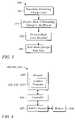
- FIG. 1illustrates a flow chart of a method of mode-based battery charge level monitoring according to the present invention.
- FIG. 2illustrates a flow chart of a method of mode-based battery cut-off determination according to the present invention.
- FIG. 3illustrates a flow chart of a method of mode-based battery cut-off determination and mode-based battery charge level monitoring according to the present invention.
- FIG. 4illustrates a block diagram of some embodiments of a digital camera having mode-based battery monitoring and/or mode-based battery cut-off determination according to the present invention.
- FIG. 5illustrates an exemplary flow chart of a digital camera control program incorporating the mode-based battery charge level monitoring and mode-based battery cut-off determination of the present invention.
- FIG. 6illustrates a flow chart of an embodiment of a Check Battery function.
- FIG. 1illustrates a flow chart of a method 100 of mode-base battery monitoring.
- the method 100 of mode-based battery monitoringdetermines a remaining charge level of or a remaining energy level in a battery used in an electronic device.
- the method of mode-based monitoringcomprises performing 110 an operation or action of the electronic device.
- the operationmay be any of a plurality of operations normally performed by the device.
- the operationsmay include, but are not limited to, capturing or recording an image, displaying an image on an image display of the camera, downloading image files from the camera to an external device, such as a personal computer (PC), and changing a zoom position of a zoom lens.
- PCpersonal computer
- the operationsmay include, but are not limited to, ‘play’, ‘pause’, ‘load CD’, and ‘eject CD’.
- the method 100further comprises determining 120 an operational mode associated with the performed operation.
- the operational modeis any operational state, or condition of the electronic device during which an operation or action of the device is performed.
- modesare defined in a given electronic device by a way the device is used and/or an implementation of a device.
- a modeis associated with, and may in fact be an action or operation of, the device.
- One skilled in the artis familiar with operational modes of electronic devices and can readily identify such modes for a given device.
- the operational modeis generally known a priori from the performed 110 operation for most electronic devices.
- the operational modeis determined 120 by simply ‘noting’ which operation was performed 110 .
- the operationis essentially equivalent to the operational mode.
- reviewing an image stored in memoryis both an operation of a digital camera and an operational mode of the camera.
- the terms ‘operation’ and ‘operational mode’will be used interchangeably herein unless otherwise specified.
- performing 110 the operation and determining 120 the operational modemay be essentially a single, combined step. However in the general case, performing 110 the operation and determining 120 the operational mode are viewed as separate and distinct steps, for the purpose of clarity only.
- Inherent in determining 120 the operational modeis determining a load or energy drain experienced by the battery as a result of the operational mode or operation thereof.
- operational modes in an electronic deviceoften differ in power or energy utilized or in a related characteristic, such as a minimum voltage required.
- a digital cameraand exemplary modes thereof.
- a first exemplary mode associated with viewing an image about to be captured or recordedmay utilize very little power, for example.
- a second exemplary mode associated with downloading images to an external device, such as a personal computer (PC)may require somewhat less power than the first exemplary mode.
- a third exemplary mode that is used to review images stored in memory of the cameramay utilize more power than the second mode
- a fourth exemplary mode associated with capturing and recording an imagemay utilize more power than the other three exemplary modes.
- the load on a battery associated with an operational modemay be determined from a known, an assumed, or a measured power consumption of the operation.
- a ‘known’ power consumptionis a power consumption that is either computed from characteristics or parameters of portions of the electronic device active during the operational mode, derived from specifications of the electronic device and the operational mode therein, or otherwise determined by one skilled in the art from knowledge of the electronic device and the operational mode. For example, one skilled in the art, given knowledge of a particular digital camera having a zoom lens, can readily determine the power consumed by a lens extension during a zoom operation. Likewise, one skilled in the art can readily determine the power consumed by the camera during an image capture mode or an image review mode.
- An ‘assumed’ power consumptionis a power consumption that is based on a similar operational mode in the same or a similar device or a power consumption that one skilled in the art arrives at based on an assumption about the operational mode and electronic device.
- a ‘measured’ power consumptionis a power consumption that is determined from measurements of an actual electronic device or a model of the electronic device for a situation in which the device is performing the operational mode.
- the method 100further comprises waiting 130 a mode-specific period of time T k , the mode-specific wait time T k being assigned to or associated with the determined 120 operational mode.
- the mode-specific wait time T kis preferably based on a recovery time of the battery, the recover time being associated with a k-th mode. Therefore, waiting 130 a mode-specific period of time T k comprises determining the recovery time for the k-th mode, and assigning a wait time T k to the k-th mode that is based on the determined recovery time.
- a recovery time of 1 -secmay be determined for an image capture mode of an example digital camera.
- the wait time for the capture modewhere the capture mode wait time is designated T capture in this example, may then be determined to be approximately 1 -sec.
- the wait time T capture of 1 -secis a time that enables the battery of the example camera to recover following an application of a load associated with the capture mode.
- a wait time T capture1 -sec is assigned to or used as the mode-specific wait time T k for the capture mode.
- the term ‘recovery’ as it relates to batteriesrefers to an empirically observed phenomena associated with the effects of loads on batteries. The effects are a result of the kinetics or the ‘chemistry’ of the battery.
- batteries used in electronic devicesare known to exhibit a battery voltage depression phenomenon when subjected to a load. When the battery is subjected to a load, the battery voltage decreases from that present prior to the application of the load. The decrease is attributed to a so-called ‘internal resistance’ of the battery. While often called ‘internal resistance’, the depression is largely a result of the battery kinetics or chemical process within the battery that produces an electric current.
- the battery voltageWhen the load is removed, the battery voltage does not immediately return to the level present prior to the application of the load. Instead, the battery voltage remains depressed for a period of time and then returns only gradually to a level close to the pre-load level. As with the internal resistance, the gradual return to a nearly pre-load battery voltage is due to the battery kinetics.
- the time that it takes for the battery voltage to recover from the depression associated with a given loadis referred to herein as a ‘recovery time’ or a ‘recovery period’. Similar effects are known for other battery characteristics, such as peak current. In general, the recovery of a battery is affected by a total load applied, a period of time the load is applied, and a charge level remaining in the battery when the load is applied and/or removed.
- the recoveryis also known to be affected by battery chemistry.
- the recovery timegenerally will be different for batteries having different chemistries.
- an alkaline batterywill typically have a different recovery time than that of a Nickel Metal Hydride (NiMH) battery.
- NiMH batterywill have a different recovery time than a Nickel Cadmium (NiCd) battery, and so on.
- recovery of a batteryis generally both a function of the load applied as discussed hereinabove and the chemistry of the battery.
- the recovery, or more particularly the recovery time, associated with a given battery characteristiccan and does impact an accuracy associated with determining the remaining charge stored in the battery using that characteristic. For example, if remaining charge is determined by measuring battery voltage, a measurement during the recovery period will tend to indicate a lower remaining charge than a measurement made after the battery has recovered (i.e., after a period of time approximately greater than or equal to the recovery time). Thus, measurements of battery voltage made during battery recovery can lead to inaccuracies in the determination of remaining charge level.
- the recovery time that is sufficient to return a battery voltage to approximately an unloaded or an approximately quiescent state once the load is removedcan be readily determined empirically by one skilled in the art for a given combination of a battery type (i.e., battery chemistry) and electronic device.
- the wait time T kis a time that is determined to be long enough, such that the recovery of the battery does not significantly effect the measurement of remaining charge in the battery.
- a wait time T k of 80% to 90% of the entire recovery timewill sufficiently minimize the effects of battery recovery on a measurement of battery voltage that is used to determine remaining charge, as described further below.
- One skilled in the artcan readily determine a relationship between the battery recovery time and the mode-specific wait time T k for a particular electronic device, battery chemistry, and mode or modes thereof.
- the mode-specific wait time T kmay be based on a length of time that the operational mode is active and/or a charge level or energy level remaining in the battery. For example, the mode-specific wait time T k may be lengthened from a nominal value for a particular mode if the mode is active for a period of time that is longer than a nominal period of time for that mode. Likewise, the mode-specific wait time T k may be shortened from the nominal value if the mode is active for a shorter period of time than a nominal time. Alternatively, for some modes, the mode specific wait time T k may be determined as a product of a mode-specific wait factor or value and a length of time the mode is active.
- the mode-specific wait time T kmay be lengthened or shorten at different stages in a discharge profile of the battery as is deemed appropriate based on knowledge of the effect of discharge on the recovery time of the battery.
- the mode-specific wait time T kmay be gradually increased for one or more of the modes to account for a general lengthening of the recovery with respect to discharge level of the battery, for example.
- the mode-specific wait time T kwhile specific for a given mode, may be vary in value according to how the device has been used over time.
- the mode-specific wait time T kis also a function of a chemistry of the battery in addition to being a function of the mode.
- a different mode-specific wait time T k for each modemay be employed for each different battery chemistry that is used in the electronic device.
- a set of mode-specific wait times T kmay be determined for a first chemistry and a different set of mode-specific wait times T′ k may be determined for a second chemistry, and so on.
- the term ‘mode-specific’is more precisely defined as ‘mode-specific and chemistry-specific’.
- mode-specificincludes embodiments that also account for the battery chemistry being used.
- the method 100optionally may further comprise determining a chemistry of the battery being used in the device (not illustrated in FIG. 1 ) prior to waiting the mode-specific time T k . Determining the battery chemistry may be accomplished through an input from a user of the device or may be ‘hardwired’ or ‘hard-coded’ in the device at a time of manufacture. For example, when the user installs a battery, the device may request that the user indicate to the device which one of a set of allowed chemistries corresponds the battery just installed.
- the devicemay employ a method of battery chemistry determination that directly or indirectly identifies the chemistry of the battery.
- a method of battery chemistry determination or identificationthat utilizes a simple test circuit in conjunction with a microcontroller that measures several distinct voltages across a battery to determine battery chemistry.
- Bean et al.in a co-pending application entitled “A Method of Battery Chemistry Identification Through Analysis of Voltage Behavior”, Ser. No. 09/859,015, which was filed May 14, 2001 and is incorporated herein by reference, disclose several in situ measurements of battery voltages under various loaded and unloaded battery conditions for battery chemistry determination.
- the described and cited methods, as well as any other method that one skilled in the art might devise to determine battery chemistry of a battery used in the electronic deviceare each within the scope of the present invention.
- determining battery chemistryneed be performed only once, e.g., immediately following replacement of the battery in the device. However, it is within the scope of the present invention to perform battery chemistry determination multiple times for each replaced battery as well.
- the determined chemistryis employed to determine the mode-specific wait time T k along with mode.
- the method 100may further comprise measuring 140 a characteristic of the battery to determine a remaining charge level of the battery. For example, a voltage of the battery may be measured 140 to determine the remaining charge level of the battery.
- the measurement 140is performed following the mode-specific wait time T k , the measurement is largely free of errors that may have been introduced in such a measurement due to the recovery of the battery.
- FIG. 2illustrates a flow chart of the method 200 of mode-based cut-off determination according to the present invention.
- the term ‘cut-off’ or ‘cut-off point’refers to a point in a discharge profile of the battery at which there is insufficient power to operate the device.
- the cut-off determinationis made by the electronic device based on a measurement or measurements of the remaining battery charge. Conventionally, the device performs a soft shut-down or enters a standby mode when the cut-off point is reached.
- the method 200 of mode-based cut-off determinationcomprises determining 210 a remaining charge level of the battery.
- Determining 210 the remaining charge levelmay comprise measuring a characteristic of the battery, such as a battery voltage and computing a remaining charge level.
- the remaining charge levelmay be computed using a look-up table or a similar method that relates the remaining charge level to the measured battery voltage.
- One of ordinary skill in the artis familiar with a variety of methods of determining 210 the remaining charge level on a battery from measurements of characteristics of the battery. All such methods for determining 210 the remaining charge level of a battery in an electronic device are within the scope of the present invention.
- the remaining charge levelis determined 210 by measuring a voltage of the battery. The measured voltage is then compared to voltages in a look-up table or on a curve of voltage with respect to remaining charge on the battery. From the comparison, a remaining charge value corresponding to the measured voltage indicates the remaining charge level in the battery.
- the method 200optionally may further comprise determining a chemistry of the battery (not illustrated in FIG. 2 ) at some point prior to determining 210 the remaining charge level.
- Batteries based on different chemistriesare known to have different amounts of remaining power or energy at different points in their respective discharge profiles wherein the points are each indicated by a measurement of a particular characteristic of the battery, such as voltage.
- the determined chemistry of the batterymay be employed to modify the determination 210 of remaining charge level. For example, if a voltage is measured and compared to a look-up table or curve to determine remaining charge level, the determined chemistry may be employed to select a look-up table or curve corresponding to the determined chemistry from among a set of such look-up tables or curves for various chemistries.
- the method 200further comprises disabling 220 operational modes for which there is insufficient remaining charge. Equivalently, an operational mode may be disabled 220 if the charge remaining is insufficient to produce a minimum voltage necessary for the mode, given the load attributed to the mode. Insufficient remaining charge means that the operational mode utilizes more power than that which remains. Thus, given information regarding which modes are available in the device, a corresponding minimum remaining charge level necessary for normal operation of each mode may be readily determined. From the corresponding minimum remaining charge level, a determination can readily be made whether a given mode can operate properly, given the determined 210 remaining charge level. In short, if the determined 210 remaining charge level is insufficient for a given mode, the mode is disabled 220 .
- a particular modesuch as an image capture mode in a digital camera, may have a minimum voltage level for normal operation. Without the minimum voltage, the camera may not reliably perform the image capture. In other words, if the determined 210 remaining charge level of the battery equates to a battery voltage that is less than the minimum voltage level for the normal image capture mode operation, then the image capture mode may not operate properly if requested by the user. Therefore, such a mode is disabled 220 , according to the present invention.
- An operational modemay be disabled 220 in a variety of ways, all of which are generally dependent on a specific electronic device and the implementation of the mode in the device. For example, in some electronic devices, a software flag may be set to indicate that a given mode is disabled 220 . In other electronic devices, a hardware-based logic line may be asserted to disable 220 a given operational mode, for example.
- a software flagmay be set to indicate that a given mode is disabled 220 .
- a hardware-based logic linemay be asserted to disable 220 a given operational mode, for example.
- One of ordinary skill in the artmay readily devise an assortment of different approaches to disabling a mode in a particular electronic device, all of which are within the scope of the present invention.
- the method 200further comprises performing 230 a requested operational mode if that mode is not disabled 220 .
- the modeis performed 230 , if and only if the requested mode is not disabled 220 .
- a decision tree or similar approachmay be used to implement such a sequence of disabling 220 and performing 230 steps using flags, for example.
- the flag associated with a requested operational modeis ‘tested’ to see whether or not that flag is set.
- the operational modeis not performed 230 . If the flag is not set, the operational mode is performed 230 in a normal manner.
- the method 200further comprises optionally notifying 240 the user of the electronic device that a requested mode has been disabled.
- a ‘Low Bat’ iconmay be illuminated on a status display if a requested operational mode is disabled 220 .
- the usermay be notified 240 by displaying a message to the user.
- the displayed messagemay inform the user that the requested operational mode is not available due to lack of power, for example.
- a combination of illuminating a ‘Low Bat’ icon and displaying a messagemay also be employed.
- a list of enabled and/or disabled operational modesmay be provided to the user by way of one of the displays available on the device.
- a method 300 of mode-based monitoring and mode-based cut-off determination for a battery powered electronic deviceis provided.
- a flow chart of the method 300 of mode-based monitoring and mode-based cut-off determinationis illustrated in FIG. 3 .
- the method 300essentially combines aspects of the method 100 and method 200 of the present invention.
- the method 300comprises determining 310 a remaining charge level of a battery.
- the method 300further comprises disabling 320 a mode for which there is insufficient power for proper operation.
- the method 300further comprises performing 330 a mode if the mode has not been disabled 320 .
- the method 300further comprises waiting 340 a mode-specific wait time T k corresponding to the performed 330 mode after the mode is performed 330 . Waiting 340 the mode-specific wait time T k occurs at an end of the performed 330 mode. After waiting 340 the mode-specific wait time T k , the method 300 may be repeated starting at determining 310 .
- FIG. 4illustrates a block diagram of the electronic device 400 .
- the electronic device 400comprises a battery 410 , a battery monitor 420 , a controller 430 , a memory 440 , and a control program 450 stored in the memory 440 .
- the control program 450comprises a set of instructions.
- the battery monitor 420measures a characteristic of the battery 410 and communicates a measured result to the controller 430 to provide battery monitoring.
- the controller 430executes the control program 450 , the instructions of which implement mode-based monitoring and/or mode-based cut-off determination, according to the present invention, in part using the measured result.
- the instruction of the control program 450implement mode-based battery monitoring.
- the instructions of the control program 450perform an operation of the electronic device and determine an operational mode associated with the performed function.
- the instructionsfurther wait a mode-specific period of time following an end of the operation.
- the mode-specific wait timeis associated with the determined operational mode and preferably, is based on the recovery time of the battery, as described hereinabove.
- the mode-specific period of timemay be both ‘mode-specific’ and battery ‘chemistry-specific’. In other words, different mode-specific wait times may be employed to account for different chemistries of the battery 410 .
- the instructionsmay further measure a characteristic of the battery to determine a remaining charge level of the battery.
- the control program 450implements the method 100 of mode-based monitoring of the present invention.
- the instruction of the control program 450 ′implement mode-based battery cut-off determination according to the present invention.
- the instructions of the control program 450 ′determine a remaining charge level of the battery and disable operational modes for which there is insufficient remaining charge.
- the instructionsenable a requested operational mode to be performed if that mode is not a disabled.
- the instructionsoptionally may notifying a user of the electronic device that a disabled mode has been requested, or provide a list of disabled modes and/or a list of enabled modes that is displayed for the user to view.
- the control program 450 ′implements the method 200 of mode-based battery cut-off determination of the present invention.
- the instructions of the control program 450 ′′implement both mode-based monitoring and mode-based battery cut-off determination. Specifically, the instructions of the control program 450 ′′ determine a remaining charge level of a battery and disable a mode for which there is insufficient power for proper operation. The instructions further enable a mode to be performed if the mode has not been disabled and the user selects the non-disabled mode. The instruction further implement waiting a mode-specific wait time T k corresponding to the performed mode after the performed mode has ended. After waiting the mode-specific wait time T k , the instructions may repeat the mode-based monitoring and cut-off determination of the battery starting at determining a remaining charge level. In a preferred embodiment, the control program 450 ′′ implements the method 300 of mode-based monitoring and mode based battery cut-off determination.
- the digital camera 400 ′′provides mode-based monitoring and mode-based cut-off determination of a battery 410 installed in the digital camera 400 ′′ through execution of a control program 450 ′′ by the controller 430 .
- the description hereinbelow of the digital camera 400 ′′is exemplary only and is not intended to limit the scope of the present invention.
- the battery monitor 420 of the example camera 400 ′′measures a battery voltage of the battery 410 .
- the controller 430utilizes the measured battery voltage to determine a charge remaining in the battery 410 .
- the camera 400 ′′is assumed to have four operational modes.
- the four exemplary modesare referred to hereinbelow as ‘review’ mode, ‘capture’ mode, ‘PC’ mode, and ‘view’ mode.
- mode 1is review mode
- mode 2is capture mode
- mode 3is PC mode
- mode 4is view mode.
- the review mode in the example camera 400 ′′requires a minimum battery voltage V review to operate properly.
- the capture modeneeds a minimum battery voltage V capture
- the PC modeneeds a minimum battery voltage V PC
- the view moderequires a minimum battery voltage V view .
- the V captureis greater than the V review .
- the V reviewis greater than the V view
- the V viewis greater than the V PC
- wait timeshave been determined for each of these modes of the example camera 400 ′′.
- the wait time T k for the review modeis T review while the wait time for the capture mode is T capture .
- the wait time for the PC modeis T PC and the wait time for the view mode is T view .
- FIG. 5illustrates a flow chart of a portion of a control program 450 ′′ used to implement the mode-based monitoring and mode-based cut-off determination for the battery 410 in the example camera 400 ′′.
- a variable of the program 450 ′′ called ‘Last State’is used to indicate which of the modes was performed.
- the variable Last State (LS)indicates the performed mode using a number corresponding to the mode.
- the LS set to ‘3’indicates that the PC mode was performed while the LS set to ‘1’ indicates that the review mode was performed.
- the LS set to ‘0’indicates no performed mode and is used for initialization purposes.
- a variable Modeis used to store a number (i.e., 0–5) indicating which mode has been requested by the user of the camera 400 ′′.
- the variable Mode equal to ‘5’is used to indicate a request to shutdown and turn off power to the camera 400 ′′.
- the flow chart illustrated in FIG. 5omits details not directly associated with implementing the mode-based monitoring and mode-based cut-off determination for the example camera 400 ′′.
- the control program 450 ′′begins at a Power On 502 operation.
- Power On 502 operationpower is applied to the electronics of the camera 400 ′′ and various components thereof are initialized.
- the Power On 502 operationis followed by an Initialize Flags 504 operation, wherein the various mode flags are initialized to ‘1’ and the LS variable and the Mode variable are both initialized to ‘0’.
- the wait time T kis initialized to ‘0’.
- FIG. 6illustrates a flow chart of an embodiment of the Check Battery function 600 .
- a Wait 602causes the function to wait for T k seconds following which a Measure Voltage 604 causes the battery monitor 420 to measure a battery voltage V bat for the battery 410 .
- the measured battery voltage V batis compared to the minimum voltage V PC needed by the PC mode in a first Decision block 606 of the Check Battery function 600 . If the voltage V bat is not greater than the voltage V PC then a message is displayed to the user indicating that there is insufficient operating power by a Message block 608 , and a Power Off 610 initiates a shutdown that ultimately shuts off power to the camera 400 ′′.
- a second Decision block 612 of the Check Battery function 600compares the voltage V bat to the minimum voltage V view for the view mode. If the voltage V bat is not greater than the voltage V view , the View flag is set to ‘0’ in a first Set block 614 indicating insufficient voltage for the view mode.
- a third Decision block 616 of the Check Battery function 600compares the voltage V bat to the minimum voltage V review for the review mode. If the voltage V bat is not greater than the voltage V review , the Review flag is set to ‘0’ in a second Set block 618 indicating insufficient voltage for the review mode.
- a fourth Decision block 620 of the Check Battery function 600compares the voltage V bat to the minimum voltage V capture for the capture mode.
- a second Message block 624 of the Check Battery function 600displays which of the modes are available and which modes are disabled.
- the Check Battery function 600ends with a Return block 626 that returns to the control program 450 ′′.
- a first Decision block 510 of the control program 450 ′′checks the requested mode and the Capture flag. If the Mode variable equals ‘2’ and the Capture flag equals ‘1’, indicating that capture mode is requested and enabled, the capture mode is performed 512 , the LS flag is set 514 to ‘2’, and the wait time T k is set 516 to equal to T capture . The program 450 ′′ then loops back to the Input Request block 506 . If the Mode variable is not equal to ‘2’ and/or the Capture flag equals ‘0’, the program 450 ′′ continues to a second Decision block 520 .
- the second Decision block 520 of the control program 450 ′′checks the requested mode. If the Mode variable is equal to ‘5’, indicating a request for shutdown, then the Power Off 522 is performed to shut down the camera 400 ′′. After the Power Off 522 is complete, the program 450 ′′ ends 524 . If the Mode variable is not equal to ‘5’, then the program 450 ′′ proceeds to a third Decision block 530 .
- the third Decision block 530 of the control program 450 ′′checks the requested mode and the Review flag. If the Mode variable equals ‘1’ and the Review flag equals ‘1’, the review mode is performed 532 , the LS flag is set 534 to ‘1’, and the wait time T k is set 536 to equal to T review . The program 450 ′′ then loops back to the Input Request 506 . If the Mode variable is not equal to ‘1’ and/or the Review flag equals ‘0’, the program 450 ′′ continues to a fourth Decision block 540 .
- the fourth Decision block 540 of the control program 450 ′′checks the requested mode and the PC flag. If the Mode variable equals ‘3’ and the PC flag equals ‘1’, the PC mode is performed 542 , the LS flag is set 544 to ‘3’, and the wait time T k is set 546 to equal to T PC . The program 450 ′′ then loops back to the Input Request 506 . If the Mode variable is not equal to ‘3’ and/or the PC flag equals ‘0’, the program 450 ′′ continues to a fifth Decision block 550 .
- the fifth Decision block 550 of the control program 450 ′′checks the requested mode and the View flag. If the Mode variable equals ‘4’ and the View flag equals ‘1’, the view mode is performed 552 , the LS flag is set 554 to ‘4’, and the wait time T k is set 556 to equal to T view . The program 450 ′′ then loops back to the Input Request 506 . If the Mode variable is not equal to ‘4’ and/or the View flag equals ‘0’, the program 450 ′′ simply loops back to the Input Request 506 .
- the control program 450 ′′when executed by the controller 430 , uses the battery monitor 420 to determine whether or not there is enough voltage available from the battery 410 to perform each of the modes of the camera 400 ′′ prior to executing any of the modes. The determination is repeated after each mode. Moreover, the program 450 ′′ adjusts the wait time T k after each time a mode is performed, such that the wait time T k corresponds to the respective mode-specific wait time of the performed mode. Thus, when the battery is again monitored, the wait time T k is the mode-specific wait time. Given the discussion and example hereinabove, one of ordinary skill can readily construct the control program 450 , 450 ′, 450 ′′ using any standard computer programming language or construct.
Landscapes
- Physics & Mathematics (AREA)
- General Physics & Mathematics (AREA)
- Secondary Cells (AREA)
- Charge And Discharge Circuits For Batteries Or The Like (AREA)
Abstract
Description
Claims (33)
Priority Applications (2)
| Application Number | Priority Date | Filing Date | Title |
|---|---|---|---|
| US10/116,888US7123155B2 (en) | 2002-04-05 | 2002-04-05 | Operational mode-based battery monitoring for a battery-powered electronic device |
| GB0307412AGB2387235B (en) | 2002-04-05 | 2003-03-31 | Operational mode-based battery monitoring for a battery-powered electronic device |
Applications Claiming Priority (1)
| Application Number | Priority Date | Filing Date | Title |
|---|---|---|---|
| US10/116,888US7123155B2 (en) | 2002-04-05 | 2002-04-05 | Operational mode-based battery monitoring for a battery-powered electronic device |
Publications (2)
| Publication Number | Publication Date |
|---|---|
| US20030189418A1 US20030189418A1 (en) | 2003-10-09 |
| US7123155B2true US7123155B2 (en) | 2006-10-17 |
Family
ID=22369823
Family Applications (1)
| Application Number | Title | Priority Date | Filing Date |
|---|---|---|---|
| US10/116,888Expired - LifetimeUS7123155B2 (en) | 2002-04-05 | 2002-04-05 | Operational mode-based battery monitoring for a battery-powered electronic device |
Country Status (2)
| Country | Link |
|---|---|
| US (1) | US7123155B2 (en) |
| GB (1) | GB2387235B (en) |
Cited By (10)
| Publication number | Priority date | Publication date | Assignee | Title |
|---|---|---|---|---|
| US20050193134A1 (en)* | 2002-04-23 | 2005-09-01 | Jari Syrjala | Method for logging a user out of a service |
| US20050195320A1 (en)* | 2004-03-03 | 2005-09-08 | Transchip, Inc. | Systems and methods for dynamic current scaling of analog functions in an imager |
| US20060239003A1 (en)* | 2005-04-20 | 2006-10-26 | Eisenson Henry L | Battery operated device with a battery life indicator |
| US20090189547A1 (en)* | 2008-01-25 | 2009-07-30 | Eveready Battery Company, Inc. | Lighting Device and Method of Control Based on Chemistry Composition of Power Source |
| US20100219836A1 (en)* | 2009-03-02 | 2010-09-02 | Sony Ericsson Mobile Communications Ab | Method and arrangement for determining energy source unit status |
| US20120253606A1 (en)* | 2011-03-31 | 2012-10-04 | Shimano Inc. | Bicycle component control apparatus |
| US20120253601A1 (en)* | 2011-03-31 | 2012-10-04 | Shimano Inc. | Bicycle component control apparatus |
| US20140217989A1 (en)* | 2011-09-02 | 2014-08-07 | Nec Corporation | Battery control system, battery controller, battery control method, and recording medium |
| US20140253693A1 (en)* | 2011-11-14 | 2014-09-11 | Sony Corporation | Information processing apparatus, method, and non-transitory computer-readable medium |
| US9267994B2 (en)* | 2008-08-07 | 2016-02-23 | Blackberry Limited | Systems and methods for monitoring deterioration of a rechargeable battery |
Families Citing this family (92)
| Publication number | Priority date | Publication date | Assignee | Title |
|---|---|---|---|---|
| US6850037B2 (en) | 1997-11-03 | 2005-02-01 | Midtronics, Inc. | In-vehicle battery monitor |
| US7003410B2 (en) | 1996-07-29 | 2006-02-21 | Midtronics, Inc. | Electronic battery tester with relative test output |
| US6566883B1 (en) | 1999-11-01 | 2003-05-20 | Midtronics, Inc. | Electronic battery tester |
| US7706991B2 (en) | 1996-07-29 | 2010-04-27 | Midtronics, Inc. | Alternator tester |
| US8198900B2 (en) | 1996-07-29 | 2012-06-12 | Midtronics, Inc. | Automotive battery charging system tester |
| US7246015B2 (en) | 1996-07-29 | 2007-07-17 | Midtronics, Inc. | Alternator tester |
| US8872517B2 (en) | 1996-07-29 | 2014-10-28 | Midtronics, Inc. | Electronic battery tester with battery age input |
| US7774151B2 (en) | 1997-11-03 | 2010-08-10 | Midtronics, Inc. | Wireless battery monitor |
| US7688074B2 (en) | 1997-11-03 | 2010-03-30 | Midtronics, Inc. | Energy management system for automotive vehicle |
| US7705602B2 (en) | 1997-11-03 | 2010-04-27 | Midtronics, Inc. | Automotive vehicle electrical system diagnostic device |
| US6871151B2 (en) | 1997-11-03 | 2005-03-22 | Midtronics, Inc. | Electronic battery tester with network communication |
| US8958998B2 (en) | 1997-11-03 | 2015-02-17 | Midtronics, Inc. | Electronic battery tester with network communication |
| US7126341B2 (en) | 1997-11-03 | 2006-10-24 | Midtronics, Inc. | Automotive vehicle electrical system diagnostic device |
| US7505856B2 (en) | 1999-04-08 | 2009-03-17 | Midtronics, Inc. | Battery test module |
| US7598744B2 (en) | 2000-03-27 | 2009-10-06 | Midtronics, Inc. | Scan tool for electronic battery tester |
| US8513949B2 (en) | 2000-03-27 | 2013-08-20 | Midtronics, Inc. | Electronic battery tester or charger with databus connection |
| US6759849B2 (en) | 2000-03-27 | 2004-07-06 | Kevin I. Bertness | Battery tester configured to receive a removable digital module |
| US7398176B2 (en) | 2000-03-27 | 2008-07-08 | Midtronics, Inc. | Battery testers with secondary functionality |
| US7446536B2 (en) | 2000-03-27 | 2008-11-04 | Midtronics, Inc. | Scan tool for electronic battery tester |
| US6941234B2 (en) | 2001-10-17 | 2005-09-06 | Midtronics, Inc. | Query based electronic battery tester |
| US7259538B2 (en)* | 2002-11-14 | 2007-08-21 | Hewlett-Packard Development Company, L.P. | Adaptive battery conditioning employing battery chemistry determination |
| DE10394007T5 (en) | 2002-12-31 | 2006-02-02 | Midtronics, Inc., Willowbrook | Apparatus and method for predicting the remaining discharge time of a battery |
| US7408358B2 (en) | 2003-06-16 | 2008-08-05 | Midtronics, Inc. | Electronic battery tester having a user interface to configure a printer |
| US9018958B2 (en) | 2003-09-05 | 2015-04-28 | Midtronics, Inc. | Method and apparatus for measuring a parameter of a vehicle electrical system |
| US9255955B2 (en) | 2003-09-05 | 2016-02-09 | Midtronics, Inc. | Method and apparatus for measuring a parameter of a vehicle electrical system |
| US7154276B2 (en) | 2003-09-05 | 2006-12-26 | Midtronics, Inc. | Method and apparatus for measuring a parameter of a vehicle electrical system |
| US8164343B2 (en) | 2003-09-05 | 2012-04-24 | Midtronics, Inc. | Method and apparatus for measuring a parameter of a vehicle electrical system |
| US7977914B2 (en) | 2003-10-08 | 2011-07-12 | Midtronics, Inc. | Battery maintenance tool with probe light |
| US7595643B2 (en) | 2003-11-11 | 2009-09-29 | Midtronics, Inc. | Apparatus and method for simulating a battery tester with a fixed resistance load |
| US7598699B2 (en) | 2004-02-20 | 2009-10-06 | Midtronics, Inc. | Replaceable clamp for electronic battery tester |
| JP4355250B2 (en)* | 2004-03-31 | 2009-10-28 | Hoya株式会社 | Digital camera |
| US7777612B2 (en) | 2004-04-13 | 2010-08-17 | Midtronics, Inc. | Theft prevention device for automotive vehicle service centers |
| US7119686B2 (en) | 2004-04-13 | 2006-10-10 | Midtronics, Inc. | Theft prevention device for automotive vehicle service centers |
| US7642786B2 (en) | 2004-06-01 | 2010-01-05 | Midtronics, Inc. | Battery tester capable of identifying faulty battery post adapters |
| US7772850B2 (en) | 2004-07-12 | 2010-08-10 | Midtronics, Inc. | Wireless battery tester with information encryption means |
| US7106070B2 (en) | 2004-07-22 | 2006-09-12 | Midtronics, Inc. | Broad-band low-inductance cables for making Kelvin connections to electrochemical cells and batteries |
| US8344685B2 (en) | 2004-08-20 | 2013-01-01 | Midtronics, Inc. | System for automatically gathering battery information |
| US8436619B2 (en) | 2004-08-20 | 2013-05-07 | Midtronics, Inc. | Integrated tag reader and environment sensor |
| US8442877B2 (en) | 2004-08-20 | 2013-05-14 | Midtronics, Inc. | Simplification of inventory management |
| US9496720B2 (en) | 2004-08-20 | 2016-11-15 | Midtronics, Inc. | System for automatically gathering battery information |
| US20060047880A1 (en)* | 2004-08-27 | 2006-03-02 | Imation Corp. | Memory device with HUB capability |
| US7545146B2 (en) | 2004-12-09 | 2009-06-09 | Midtronics, Inc. | Apparatus and method for predicting battery capacity and fitness for service from a battery dynamic parameter and a recovery voltage differential |
| US7710119B2 (en) | 2004-12-09 | 2010-05-04 | Midtronics, Inc. | Battery tester that calculates its own reference values |
| US7498767B2 (en) | 2005-02-16 | 2009-03-03 | Midtronics, Inc. | Centralized data storage of condition of a storage battery at its point of sale |
| US7176806B2 (en)* | 2005-02-23 | 2007-02-13 | Eaglepicher Energy Products Corporation | Physical key to facilitate an inactive mode for a state-of-charge indicator within a battery |
| US20070063676A1 (en)* | 2005-09-22 | 2007-03-22 | Davani Shouresh T | Multiple mode electronic device and method for indicating remaining battery capacity level |
| EP1940150A4 (en)* | 2005-10-20 | 2010-06-02 | Nikon Corp | Camera-equipped electronic device |
| US7848527B2 (en)* | 2006-02-27 | 2010-12-07 | Apple Inc. | Dynamic power management in a portable media delivery system |
| US8302150B2 (en)* | 2006-09-08 | 2012-10-30 | Samsung Electronics Co., Ltd. | Method and system for managing the functionality of user devices |
| US7791348B2 (en) | 2007-02-27 | 2010-09-07 | Midtronics, Inc. | Battery tester with promotion feature to promote use of the battery tester by providing the user with codes having redeemable value |
| US7808375B2 (en) | 2007-04-16 | 2010-10-05 | Midtronics, Inc. | Battery run down indicator |
| GB2463829B (en) | 2007-07-17 | 2012-11-21 | Midtronics Inc | Battery tester for electric vehicle |
| US9274157B2 (en) | 2007-07-17 | 2016-03-01 | Midtronics, Inc. | Battery tester for electric vehicle |
| US8248023B2 (en)* | 2007-11-04 | 2012-08-21 | GM Global Technology Operations LLC | Method of externally charging a powertrain |
| US8203345B2 (en) | 2007-12-06 | 2012-06-19 | Midtronics, Inc. | Storage battery and battery tester |
| US9588185B2 (en) | 2010-02-25 | 2017-03-07 | Keith S. Champlin | Method and apparatus for detecting cell deterioration in an electrochemical cell or battery |
| WO2011109343A2 (en) | 2010-03-03 | 2011-09-09 | Midtronics, Inc. | Monitor for front terminal batteries |
| US9229062B2 (en) | 2010-05-27 | 2016-01-05 | Midtronics, Inc. | Electronic storage battery diagnostic system |
| US11740294B2 (en) | 2010-06-03 | 2023-08-29 | Midtronics, Inc. | High use battery pack maintenance |
| US10046649B2 (en) | 2012-06-28 | 2018-08-14 | Midtronics, Inc. | Hybrid and electric vehicle battery pack maintenance device |
| US8738309B2 (en) | 2010-09-30 | 2014-05-27 | Midtronics, Inc. | Battery pack maintenance for electric vehicles |
| US20110300416A1 (en) | 2010-06-03 | 2011-12-08 | Bertness Kevin I | Battery pack maintenance for electric vehicle |
| US9419311B2 (en) | 2010-06-18 | 2016-08-16 | Midtronics, Inc. | Battery maintenance device with thermal buffer |
| US9201120B2 (en) | 2010-08-12 | 2015-12-01 | Midtronics, Inc. | Electronic battery tester for testing storage battery |
| US8954017B2 (en)* | 2011-08-17 | 2015-02-10 | Broadcom Corporation | Clock signal multiplication to reduce noise coupled onto a transmission communication signal of a communications device |
| JP5998454B2 (en)* | 2011-11-07 | 2016-09-28 | ソニー株式会社 | Control device, control method, and control system |
| WO2013070850A2 (en) | 2011-11-10 | 2013-05-16 | Midtronics, Inc. | Battery pack tester |
| JP5739358B2 (en)* | 2012-02-07 | 2015-06-24 | 京セラ株式会社 | Apparatus, method, and program |
| US11325479B2 (en) | 2012-06-28 | 2022-05-10 | Midtronics, Inc. | Hybrid and electric vehicle battery maintenance device |
| US9851411B2 (en) | 2012-06-28 | 2017-12-26 | Keith S. Champlin | Suppressing HF cable oscillations during dynamic measurements of cells and batteries |
| US9244100B2 (en) | 2013-03-15 | 2016-01-26 | Midtronics, Inc. | Current clamp with jaw closure detection |
| US9312575B2 (en) | 2013-05-16 | 2016-04-12 | Midtronics, Inc. | Battery testing system and method |
| US10843574B2 (en) | 2013-12-12 | 2020-11-24 | Midtronics, Inc. | Calibration and programming of in-vehicle battery sensors |
| EP2897229A1 (en) | 2014-01-16 | 2015-07-22 | Midtronics, Inc. | Battery clamp with endoskeleton design |
| US10473555B2 (en) | 2014-07-14 | 2019-11-12 | Midtronics, Inc. | Automotive maintenance system |
| US10222397B2 (en) | 2014-09-26 | 2019-03-05 | Midtronics, Inc. | Cable connector for electronic battery tester |
| WO2016123075A1 (en) | 2015-01-26 | 2016-08-04 | Midtronics, Inc. | Alternator tester |
| US9966676B2 (en) | 2015-09-28 | 2018-05-08 | Midtronics, Inc. | Kelvin connector adapter for storage battery |
| US10608353B2 (en) | 2016-06-28 | 2020-03-31 | Midtronics, Inc. | Battery clamp |
| US12320857B2 (en) | 2016-10-25 | 2025-06-03 | Midtronics, Inc. | Electrical load for electronic battery tester and electronic battery tester including such electrical load |
| US11054480B2 (en) | 2016-10-25 | 2021-07-06 | Midtronics, Inc. | Electrical load for electronic battery tester and electronic battery tester including such electrical load |
| US11513160B2 (en) | 2018-11-29 | 2022-11-29 | Midtronics, Inc. | Vehicle battery maintenance device |
| US11566972B2 (en) | 2019-07-31 | 2023-01-31 | Midtronics, Inc. | Tire tread gauge using visual indicator |
| US11545839B2 (en) | 2019-11-05 | 2023-01-03 | Midtronics, Inc. | System for charging a series of connected batteries |
| US11668779B2 (en) | 2019-11-11 | 2023-06-06 | Midtronics, Inc. | Hybrid and electric vehicle battery pack maintenance device |
| US11474153B2 (en) | 2019-11-12 | 2022-10-18 | Midtronics, Inc. | Battery pack maintenance system |
| CN111163388B (en)* | 2019-12-31 | 2021-08-10 | 歌尔股份有限公司 | Management method and device for charging path of Bluetooth headset and readable storage medium |
| DE102020216599A1 (en) | 2019-12-31 | 2021-07-01 | Midtronics, Inc. | Intelligent module interface for a battery maintenance device |
| US11973202B2 (en) | 2019-12-31 | 2024-04-30 | Midtronics, Inc. | Intelligent module interface for battery maintenance device |
| US11486930B2 (en) | 2020-01-23 | 2022-11-01 | Midtronics, Inc. | Electronic battery tester with battery clamp storage holsters |
| US12330513B2 (en) | 2022-02-14 | 2025-06-17 | Midtronics, Inc. | Battery maintenance device with high voltage connector |
| US12392833B2 (en) | 2022-05-09 | 2025-08-19 | Midtronics, Inc. | Electronic battery tester |
Citations (19)
| Publication number | Priority date | Publication date | Assignee | Title |
|---|---|---|---|---|
| US3979657A (en) | 1973-05-15 | 1976-09-07 | Westinghouse Electric Corporation | Battery monitor with automatic scale and recycle prevents |
| US4994728A (en) | 1988-02-24 | 1991-02-19 | Mitsubishi Denki Kabushiki Kaisha | Apparatus for diagnosing vehicle-mounted battery |
| EP0592965A2 (en) | 1992-10-13 | 1994-04-20 | Sanyo Electric Co., Ltd. | Battery monitoring system and battery pack |
| US5317362A (en) | 1991-06-13 | 1994-05-31 | Fuji Photo Optical Co., Ltd. | Control circuit for camera having auxiliary light source |
| US5352982A (en) | 1990-10-16 | 1994-10-04 | Honda Giken Kogyo Kabushiki Kaisha | Method and apparatus for displaying a residual electric charge of a battery for an electrically driven vehicle |
| US5381096A (en)* | 1992-04-09 | 1995-01-10 | Hirzel; Edgar A. | Method and apparatus for measuring the state-of-charge of a battery system |
| US5798702A (en) | 1996-04-18 | 1998-08-25 | Suzuki Motor Corporation | Residual battery capacity display device for electric vehicle |
| US5929594A (en)* | 1996-08-29 | 1999-07-27 | Toyota Jidosha Kabushiki Kaisha | Fuel-cells system, electric vehicle with fuel-cells system, and method of controlling supply of electric power |
| US6046574A (en) | 1999-06-04 | 2000-04-04 | Sony Corporation | Battery dropout correction for battery monitoring in mobile unit |
| US6091909A (en) | 1998-11-24 | 2000-07-18 | Eastman Kodak Company | Battery control for digital camera and integral printer |
| US6107802A (en)* | 1992-07-08 | 2000-08-22 | Matthews; Wallace Edward | Battery pack with monitoring function utilizing association with a battery charging system |
| US6134457A (en) | 1997-07-16 | 2000-10-17 | Samsung Electronics Co., Ltd. | Device and method for monitoring a battery in a mobile communication terminal |
| US6167309A (en)* | 1997-09-15 | 2000-12-26 | Cardiac Pacemakers, Inc. | Method for monitoring end of life for battery |
| US6174617B1 (en)* | 1998-07-20 | 2001-01-16 | Sony Chemicals Corporation | Communication method, remaining capacity calculation method, total capacity calculation method, overcharge protection method, information display method, and battery pack |
| US6201977B1 (en) | 1998-04-24 | 2001-03-13 | Micron Technology, Inc. | Power-saving mode for portable communication devices |
| US6215275B1 (en) | 1999-10-29 | 2001-04-10 | Hewlett-Packard Company | Method for the automatic determination of battery chemistry in portable electronic devices |
| US6233016B1 (en) | 1996-04-16 | 2001-05-15 | Apple Computer, Inc. | System and method for managing utilization of a battery |
| US6351611B1 (en)* | 1999-04-08 | 2002-02-26 | Olympus Optical Co., Ltd. | Battery check system for use in cameras |
| EP1257034A2 (en) | 2001-05-09 | 2002-11-13 | Makita Corporation | Power tools |
- 2002
- 2002-04-05USUS10/116,888patent/US7123155B2/ennot_activeExpired - Lifetime
- 2003
- 2003-03-31GBGB0307412Apatent/GB2387235B/ennot_activeExpired - Fee Related
Patent Citations (19)
| Publication number | Priority date | Publication date | Assignee | Title |
|---|---|---|---|---|
| US3979657A (en) | 1973-05-15 | 1976-09-07 | Westinghouse Electric Corporation | Battery monitor with automatic scale and recycle prevents |
| US4994728A (en) | 1988-02-24 | 1991-02-19 | Mitsubishi Denki Kabushiki Kaisha | Apparatus for diagnosing vehicle-mounted battery |
| US5352982A (en) | 1990-10-16 | 1994-10-04 | Honda Giken Kogyo Kabushiki Kaisha | Method and apparatus for displaying a residual electric charge of a battery for an electrically driven vehicle |
| US5317362A (en) | 1991-06-13 | 1994-05-31 | Fuji Photo Optical Co., Ltd. | Control circuit for camera having auxiliary light source |
| US5381096A (en)* | 1992-04-09 | 1995-01-10 | Hirzel; Edgar A. | Method and apparatus for measuring the state-of-charge of a battery system |
| US6107802A (en)* | 1992-07-08 | 2000-08-22 | Matthews; Wallace Edward | Battery pack with monitoring function utilizing association with a battery charging system |
| EP0592965A2 (en) | 1992-10-13 | 1994-04-20 | Sanyo Electric Co., Ltd. | Battery monitoring system and battery pack |
| US6233016B1 (en) | 1996-04-16 | 2001-05-15 | Apple Computer, Inc. | System and method for managing utilization of a battery |
| US5798702A (en) | 1996-04-18 | 1998-08-25 | Suzuki Motor Corporation | Residual battery capacity display device for electric vehicle |
| US5929594A (en)* | 1996-08-29 | 1999-07-27 | Toyota Jidosha Kabushiki Kaisha | Fuel-cells system, electric vehicle with fuel-cells system, and method of controlling supply of electric power |
| US6134457A (en) | 1997-07-16 | 2000-10-17 | Samsung Electronics Co., Ltd. | Device and method for monitoring a battery in a mobile communication terminal |
| US6167309A (en)* | 1997-09-15 | 2000-12-26 | Cardiac Pacemakers, Inc. | Method for monitoring end of life for battery |
| US6201977B1 (en) | 1998-04-24 | 2001-03-13 | Micron Technology, Inc. | Power-saving mode for portable communication devices |
| US6174617B1 (en)* | 1998-07-20 | 2001-01-16 | Sony Chemicals Corporation | Communication method, remaining capacity calculation method, total capacity calculation method, overcharge protection method, information display method, and battery pack |
| US6091909A (en) | 1998-11-24 | 2000-07-18 | Eastman Kodak Company | Battery control for digital camera and integral printer |
| US6351611B1 (en)* | 1999-04-08 | 2002-02-26 | Olympus Optical Co., Ltd. | Battery check system for use in cameras |
| US6046574A (en) | 1999-06-04 | 2000-04-04 | Sony Corporation | Battery dropout correction for battery monitoring in mobile unit |
| US6215275B1 (en) | 1999-10-29 | 2001-04-10 | Hewlett-Packard Company | Method for the automatic determination of battery chemistry in portable electronic devices |
| EP1257034A2 (en) | 2001-05-09 | 2002-11-13 | Makita Corporation | Power tools |
Cited By (18)
| Publication number | Priority date | Publication date | Assignee | Title |
|---|---|---|---|---|
| US20050193134A1 (en)* | 2002-04-23 | 2005-09-01 | Jari Syrjala | Method for logging a user out of a service |
| US20050195320A1 (en)* | 2004-03-03 | 2005-09-08 | Transchip, Inc. | Systems and methods for dynamic current scaling of analog functions in an imager |
| US7755698B2 (en)* | 2004-03-03 | 2010-07-13 | Samsung Electronics, Co., Ltd. | Systems and methods for dynamic current scaling of analog functions in an imager |
| US20060239003A1 (en)* | 2005-04-20 | 2006-10-26 | Eisenson Henry L | Battery operated device with a battery life indicator |
| US7295129B2 (en)* | 2005-04-20 | 2007-11-13 | Henry Lon Eisenson | Battery operated device with a battery life indicator |
| US8120268B2 (en) | 2008-01-25 | 2012-02-21 | Eveready Battery Company, Inc. | Lighting device and method of control based on chemistry composition of power source |
| US20090189547A1 (en)* | 2008-01-25 | 2009-07-30 | Eveready Battery Company, Inc. | Lighting Device and Method of Control Based on Chemistry Composition of Power Source |
| WO2009094455A3 (en)* | 2008-01-25 | 2009-11-05 | Eveready Battery Company, Inc. | Lighting device and method of control based on chemistry composition of power source |
| US9267994B2 (en)* | 2008-08-07 | 2016-02-23 | Blackberry Limited | Systems and methods for monitoring deterioration of a rechargeable battery |
| WO2010099836A1 (en)* | 2009-03-02 | 2010-09-10 | Sony Ericsson Mobile Communications Ab | Method and arrangement for determining energy source unit status |
| US20100219836A1 (en)* | 2009-03-02 | 2010-09-02 | Sony Ericsson Mobile Communications Ab | Method and arrangement for determining energy source unit status |
| US20120253606A1 (en)* | 2011-03-31 | 2012-10-04 | Shimano Inc. | Bicycle component control apparatus |
| US20120253601A1 (en)* | 2011-03-31 | 2012-10-04 | Shimano Inc. | Bicycle component control apparatus |
| US9284016B2 (en)* | 2011-03-31 | 2016-03-15 | Shimano Inc. | Bicycle component control apparatus |
| US10086708B2 (en)* | 2011-03-31 | 2018-10-02 | Shimano Inc. | Bicycle component control apparatus |
| US20140217989A1 (en)* | 2011-09-02 | 2014-08-07 | Nec Corporation | Battery control system, battery controller, battery control method, and recording medium |
| US20140253693A1 (en)* | 2011-11-14 | 2014-09-11 | Sony Corporation | Information processing apparatus, method, and non-transitory computer-readable medium |
| US10469767B2 (en)* | 2011-11-14 | 2019-11-05 | Sony Corporation | Information processing apparatus, method, and non-transitory computer-readable medium |
Also Published As
| Publication number | Publication date |
|---|---|
| GB2387235B (en) | 2005-09-28 |
| GB2387235A (en) | 2003-10-08 |
| GB0307412D0 (en) | 2003-05-07 |
| US20030189418A1 (en) | 2003-10-09 |
Similar Documents
| Publication | Publication Date | Title |
|---|---|---|
| US7123155B2 (en) | Operational mode-based battery monitoring for a battery-powered electronic device | |
| US6400123B1 (en) | Battery fuel gauging using battery chemistry identification | |
| US20040095096A1 (en) | Adaptive battery conditioning employing battery chemistry determination | |
| US8598849B2 (en) | In-situ battery health detector and end-of-life indicator | |
| JP6991591B2 (en) | How to predict the state of charge of the battery | |
| KR101770933B1 (en) | Monitoring a battery in a portable electronic device | |
| JP4474095B2 (en) | Adaptable residual quantity measurement for battery-powered electronics | |
| US7304454B2 (en) | Information processing apparatus for setting charge-start criteria level based on power supply drive history | |
| US8035351B2 (en) | Information processing apparatus | |
| US20130063074A1 (en) | Battery charge/discharge management system and method | |
| US8483983B2 (en) | Information processing apparatus and battery degradation detection method | |
| US8421357B2 (en) | Method of driving a flash device and a number of loads powered by a battery and handheld electronic device including the same | |
| US8502505B2 (en) | Battery driving device, load control method, integrated circuit and load control program | |
| CN116560485B (en) | Power management method and system of intelligent terminal equipment | |
| JP2021035286A (en) | Charge control method, charge control device, charging device, and charging system | |
| US8022676B2 (en) | Electronic device | |
| JP4030408B2 (en) | Operating frequency control system and method | |
| JP4732830B2 (en) | Low battery judgment voltage setting method | |
| KR20010061336A (en) | Portable computer having battery calibration function notified of user or automatically performed in proper moment and method of the same | |
| CN120300977A (en) | Battery activation method and related device | |
| TW451514B (en) | Method and system for assuring the lifetime of charging battery built in a portable electronic device | |
| JP2022127963A (en) | Electronic device, information output method, and program | |
| JP2009240102A (en) | Electronic equipment | |
| KR20050101955A (en) | Battery residual amount alarm method for mobile communication terminal | |
| CA2691328A1 (en) | Method of driving a flash device and a number of loads powered by a battery and handheld electronic device including the same |
Legal Events
| Date | Code | Title | Description |
|---|---|---|---|
| AS | Assignment | Owner name:HEWLETT-PACKARD COMPANY, COLORADO Free format text:ASSIGNMENT OF ASSIGNORS INTEREST;ASSIGNOR:SCHINNER, CHARLES E.;REEL/FRAME:013191/0843 Effective date:20020329 | |
| AS | Assignment | Owner name:HEWLETT-PACKARD DEVELOPMENT COMPANY, L.P., COLORADO Free format text:ASSIGNMENT OF ASSIGNORS INTEREST;ASSIGNOR:HEWLETT-PACKARD COMPANY;REEL/FRAME:013776/0928 Effective date:20030131 Owner name:HEWLETT-PACKARD DEVELOPMENT COMPANY, L.P., COLORAD Free format text:ASSIGNMENT OF ASSIGNORS INTEREST;ASSIGNOR:HEWLETT-PACKARD COMPANY;REEL/FRAME:013776/0928 Effective date:20030131 Owner name:HEWLETT-PACKARD DEVELOPMENT COMPANY, L.P.,COLORADO Free format text:ASSIGNMENT OF ASSIGNORS INTEREST;ASSIGNOR:HEWLETT-PACKARD COMPANY;REEL/FRAME:013776/0928 Effective date:20030131 | |
| STCF | Information on status: patent grant | Free format text:PATENTED CASE | |
| CC | Certificate of correction | ||
| FPAY | Fee payment | Year of fee payment:4 | |
| AS | Assignment | Owner name:HEWLETT-PACKARD COMPANY, COLORADO Free format text:ASSIGNMENT OF ASSIGNORS INTEREST;ASSIGNOR:SCHINNER, CHARLES E.;REEL/FRAME:030631/0357 Effective date:20020329 | |
| FPAY | Fee payment | Year of fee payment:8 | |
| MAFP | Maintenance fee payment | Free format text:PAYMENT OF MAINTENANCE FEE, 12TH YEAR, LARGE ENTITY (ORIGINAL EVENT CODE: M1553) Year of fee payment:12 |