US7122884B2 - Robust leaded molded packages and methods for forming the same - Google Patents
Robust leaded molded packages and methods for forming the sameDownload PDFInfo
- Publication number
- US7122884B2 US7122884B2US10/413,668US41366803AUS7122884B2US 7122884 B2US7122884 B2US 7122884B2US 41366803 AUS41366803 AUS 41366803AUS 7122884 B2US7122884 B2US 7122884B2
- Authority
- US
- United States
- Prior art keywords
- die
- semiconductor
- leadframe
- die attach
- solder
- Prior art date
- Legal status (The legal status is an assumption and is not a legal conclusion. Google has not performed a legal analysis and makes no representation as to the accuracy of the status listed.)
- Expired - Lifetime
Links
Images


Classifications
- H—ELECTRICITY
- H01—ELECTRIC ELEMENTS
- H01L—SEMICONDUCTOR DEVICES NOT COVERED BY CLASS H10
- H01L23/00—Details of semiconductor or other solid state devices
- H01L23/48—Arrangements for conducting electric current to or from the solid state body in operation, e.g. leads, terminal arrangements ; Selection of materials therefor
- H01L23/488—Arrangements for conducting electric current to or from the solid state body in operation, e.g. leads, terminal arrangements ; Selection of materials therefor consisting of soldered or bonded constructions
- H01L23/495—Lead-frames or other flat leads
- H01L23/49541—Geometry of the lead-frame
- H01L23/49562—Geometry of the lead-frame for individual devices of subclass H10D
- H—ELECTRICITY
- H01—ELECTRIC ELEMENTS
- H01L—SEMICONDUCTOR DEVICES NOT COVERED BY CLASS H10
- H01L2224/00—Indexing scheme for arrangements for connecting or disconnecting semiconductor or solid-state bodies and methods related thereto as covered by H01L24/00
- H01L2224/01—Means for bonding being attached to, or being formed on, the surface to be connected, e.g. chip-to-package, die-attach, "first-level" interconnects; Manufacturing methods related thereto
- H01L2224/10—Bump connectors; Manufacturing methods related thereto
- H01L2224/15—Structure, shape, material or disposition of the bump connectors after the connecting process
- H01L2224/16—Structure, shape, material or disposition of the bump connectors after the connecting process of an individual bump connector
- H01L2224/161—Disposition
- H01L2224/16151—Disposition the bump connector connecting between a semiconductor or solid-state body and an item not being a semiconductor or solid-state body, e.g. chip-to-substrate, chip-to-passive
- H01L2224/16221—Disposition the bump connector connecting between a semiconductor or solid-state body and an item not being a semiconductor or solid-state body, e.g. chip-to-substrate, chip-to-passive the body and the item being stacked
- H01L2224/16245—Disposition the bump connector connecting between a semiconductor or solid-state body and an item not being a semiconductor or solid-state body, e.g. chip-to-substrate, chip-to-passive the body and the item being stacked the item being metallic
- H—ELECTRICITY
- H01—ELECTRIC ELEMENTS
- H01L—SEMICONDUCTOR DEVICES NOT COVERED BY CLASS H10
- H01L2224/00—Indexing scheme for arrangements for connecting or disconnecting semiconductor or solid-state bodies and methods related thereto as covered by H01L24/00
- H01L2224/73—Means for bonding being of different types provided for in two or more of groups H01L2224/10, H01L2224/18, H01L2224/26, H01L2224/34, H01L2224/42, H01L2224/50, H01L2224/63, H01L2224/71
- H01L2224/732—Location after the connecting process
- H01L2224/73251—Location after the connecting process on different surfaces
- H01L2224/73253—Bump and layer connectors
- H—ELECTRICITY
- H01—ELECTRIC ELEMENTS
- H01L—SEMICONDUCTOR DEVICES NOT COVERED BY CLASS H10
- H01L2924/00—Indexing scheme for arrangements or methods for connecting or disconnecting semiconductor or solid-state bodies as covered by H01L24/00
- H01L2924/01—Chemical elements
- H01L2924/01046—Palladium [Pd]
- H—ELECTRICITY
- H01—ELECTRIC ELEMENTS
- H01L—SEMICONDUCTOR DEVICES NOT COVERED BY CLASS H10
- H01L2924/00—Indexing scheme for arrangements or methods for connecting or disconnecting semiconductor or solid-state bodies as covered by H01L24/00
- H01L2924/01—Chemical elements
- H01L2924/01078—Platinum [Pt]
- H—ELECTRICITY
- H01—ELECTRIC ELEMENTS
- H01L—SEMICONDUCTOR DEVICES NOT COVERED BY CLASS H10
- H01L2924/00—Indexing scheme for arrangements or methods for connecting or disconnecting semiconductor or solid-state bodies as covered by H01L24/00
- H01L2924/01—Chemical elements
- H01L2924/01079—Gold [Au]
- H—ELECTRICITY
- H01—ELECTRIC ELEMENTS
- H01L—SEMICONDUCTOR DEVICES NOT COVERED BY CLASS H10
- H01L2924/00—Indexing scheme for arrangements or methods for connecting or disconnecting semiconductor or solid-state bodies as covered by H01L24/00
- H01L2924/013—Alloys
- H01L2924/0132—Binary Alloys
- H01L2924/01322—Eutectic Alloys, i.e. obtained by a liquid transforming into two solid phases
- H—ELECTRICITY
- H01—ELECTRIC ELEMENTS
- H01L—SEMICONDUCTOR DEVICES NOT COVERED BY CLASS H10
- H01L2924/00—Indexing scheme for arrangements or methods for connecting or disconnecting semiconductor or solid-state bodies as covered by H01L24/00
- H01L2924/10—Details of semiconductor or other solid state devices to be connected
- H01L2924/11—Device type
- H01L2924/13—Discrete devices, e.g. 3 terminal devices
- H01L2924/1304—Transistor
- H01L2924/1305—Bipolar Junction Transistor [BJT]
- H—ELECTRICITY
- H01—ELECTRIC ELEMENTS
- H01L—SEMICONDUCTOR DEVICES NOT COVERED BY CLASS H10
- H01L2924/00—Indexing scheme for arrangements or methods for connecting or disconnecting semiconductor or solid-state bodies as covered by H01L24/00
- H01L2924/10—Details of semiconductor or other solid state devices to be connected
- H01L2924/11—Device type
- H01L2924/13—Discrete devices, e.g. 3 terminal devices
- H01L2924/1304—Transistor
- H01L2924/1306—Field-effect transistor [FET]
- H01L2924/13091—Metal-Oxide-Semiconductor Field-Effect Transistor [MOSFET]
Definitions
- the flip chip in a leaded molded packageincludes a leadframe structure that has a die attach pad and leads that extend away from the die attach pad.
- the die attach padis coupled to the front side of a semiconductor die with solder.
- a molding materialcovers the die attach pad and the front side of the semiconductor die, while the back side of the semiconductor die is exposed through the molding material.
- the leadsextend laterally away from the molding material and are substantially co-planar with the back side of the semiconductor die and a surface of the molding material.
- the front side of the semiconductor diemay correspond to the gate region and the source region of a MOSFET (metal oxide semiconductor field effect transistor) in the semiconductor die.
- the back side of the semiconductor diemay correspond to the drain region of the MOSFET.
- the above-described semiconductor packagehas a number of advantages. First, because there is a substantially direct electrical connection between the back side of the semiconductor die and the circuit substrate, and because there are short, low-resistance conductive paths between the source and gate regions in the semiconductor die, and the circuit substrate, the die package resistance is nearly eliminated, allowing for the industry's lowest R DS(ON) for the same package footprint. R DS(ON) is the on-resistance that is associated with turning a MOSFET in the die package on from an off-state. Second, the above-described semiconductor package is thin.
- a flip chip in a leaded molded packagecan have a height of less than about 1.0 mm.
- the flip chip in a leaded molded packagecan have the same or better electrical and thermal performance, while being smaller than a standard SOIC-8 package.
- Thin semiconductor packagesare especially desirable for small portable electronic devices such as wireless phones and laptop computers.
- the above-described semiconductor packagehas a number of advantages, a number of improvements could be made.
- a number of problemscan occur.
- the problemsinclude, for example, silicon cracks that form because of an uneven die standoff from the die attach region of the leadframe structure, moisture seepage into the semiconductor package, delamination between the leadframe structure and the molding material, and molding material bleed on an exposed die surface and leads (which can hinder the package from functioning efficiently or potentially fail during device applications).
- Other problemsinclude poor solder adhesion between the circuit board bonding pads and the semiconductor die and uneven cutting during the singulation process.
- Embodiments of the inventionare directed to semiconductor packages and methods for making semiconductor packages. Some embodiments of the invention are directed to flip chip in leaded molded packages (FLMP). Although flip chip in leaded molded packages are described in detail below, some embodiments of the invention can be extended to other types of semiconductor packages.
- FLMPflip chip in leaded molded packages
- One embodiment of the inventionis directed to a semiconductor package comprising: (a) a semiconductor die including a first side and a second side, wherein the semiconductor die further includes a bond pad at the first side, the bond pad comprising an uneven surface; (b) a leadframe structure comprising (i) a die attach region, and (ii) a plurality of leads extending away from the die attach region; (c) a plurality of solder structures between the semiconductor die and the leadframe structure and coupling the die attach region to the semiconductor die; (d) a depression formed in the leadframe structure, the depression being between the one of the solder structures in the plurality of solder structures, and one of the leads in the plurality of leads; and (e) a molding material covering the die attach region of the leadframe structure, the plurality of solder structures, and the first side of the semiconductor die.
- Another embodiment of the inventionis directed to a semiconductor package comprising: (a) a semiconductor die including a first side and a second side; (b) a leadframe structure comprising (i) a die attach region comprising an aperture that passes through the die attach region, and (ii) a plurality of leads extending away from the die attach region; (c) a plurality of solder structures between the semiconductor die and the leadframe structure and coupling the die attach region to the semiconductor die; (d) a depression in the leadframe structure, the depression being between the one of the solder structures in the plurality of leadframe structures, and one of the leads in the plurality of leads; and (e) a molding material covering the die attach region of the leadframe structure, the plurality of solder structures, and the first side of the semiconductor die, and wherein the molding material is also within the aperture of the die attach region.
- Another embodiment of the inventionis directed to a semiconductor package comprising: (a) a semiconductor die including a first side and a second side, wherein the semiconductor die further includes a bond pad at the first side, the bond pad comprising an uneven surface; (b) a leadframe structure comprising (i) a die attach region and an aperture in the die attach region, and (ii) a plurality of leads extending away from the die attach region; (c) a plurality of solder structures between the semiconductor die and the leadframe structure and coupling the die attach region to the semiconductor die; and (d) a molding material covering the die attach region of the leadframe structure, the solder structure, and the first side of the semiconductor die, and wherein the molding material is also within the aperture.
- Another embodiment of the inventionis directed to a method for forming a semiconductor package, the method comprising: (a) providing a plurality of leadframe structures in a leadframe carrier comprising a saw guide slot, wherein the leadframe carrier comprises a plurality of leadframe structures, each leadframe structure comprising (i) a die attach region, and (ii) a plurality of leads extending away from the die attach region; (b) attaching semiconductor dies to the die attach regions, wherein a plurality of solder structures is between each semiconductor die and each die attach region; (c) molding a molding material around at least a portion of each semiconductor die and at least a portion of each die attach region; and (d) cutting the leadframe carrier with a saw using the saw guide slot.
- Another embodimentis directed to a method for forming a semiconductor package, the method comprising: (a) providing a leadframe structure comprising (i) a die attach region comprising an aperture, (ii) a plurality of leads extending away from the die attach region, and (iii) a plurality of depressions, each depression being proximate to an inner portion of a lead; (b) attaching a semiconductor die to the die attach region, wherein the semiconductor die comprises a first side, a second side, and a bond pad at the first side, and wherein a plurality of solder structures is between the semiconductor die and the die attach region; (c) reflowing the plurality of solder structures; and (d) molding a molding material around at least a portion of the semiconductor die and at least a portion of each die attach region, wherein the molding material passes through the aperture in the die attach region.
- Another embodiment of the inventionis directed to a method for forming a semiconductor package, the method comprising: (a) providing a leadframe structure comprising (i) a die attach region comprising an aperture, (ii) a plurality of leads extending away from the die attach region, and (iii) a plurality of depressions, each depression being proximate to an inner portion of a lead; (b) attaching a semiconductor die to the die attach region, wherein the semiconductor die comprises a first side, a second side, and a bond pad at the first side, and wherein a plurality of solder structures is between the semiconductor die and the die attach region; (c) reflowing the plurality of solder structures; and (d) molding a molding material around at least a portion of the semiconductor die and at least a portion of each die attach region, wherein the molding material passes through the aperture in the die attach region.
- Another embodiment of the inventionis directed to a method for forming a semiconductor package, the method comprising: (a) providing a leadframe structure comprising (i) a die attach region, (ii) a plurality of leads extending away from the die attach region, and (iii) a plurality of depressions, each depression being proximate to an inner portion of a lead in the plurality of leads and the die attach region; (b) attaching a semiconductor die to the die attach region, wherein the semiconductor die comprises a first side, a second side, and a bond pad having an uneven surface at the first side, and wherein a plurality of solder structures is between the semiconductor die and the die attach region; (c) reflowing the plurality of solder structures; and (d) molding a molding material around each at least a portion of the semiconductor die and at least a portion of each die attach region.
- FIG. 1shows a flowchart illustrating a method according to an embodiment of the invention.
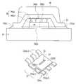
- FIG. 2shows a side cross-sectional view of a flip chip in leaded molded package mounted on a circuit substrate.
- FIG. 3( a )shows a perspective view of a leadframe structure according to an embodiment of the invention.
- FIG. 3( b )shows a perspective view of a leadframe structure according to an embodiment of the invention with depressions.
- FIG. 3( c )shows a side cross-sectional view of a leadframe structure showing a depression between a portion of a lead and a portion of a die attach pad.
- FIG. 3( d )shows a side view of how the position of a mounted die can shift during solder reflow, if depressions are not present in the leadframe structure.
- FIG. 3( e )shows a side view of how the position of a mounted die does not shift during solder reflow when depressions are present in the leadframe structure.
- FIG. 4( a )shows an SEM (scanning electron microscope) photograph of a cross-section of a scalloped-shaped source pad.
- FIG. 4( b )shows an SEM photograph of a cross-section of a gate pad with an uneven top surface.
- FIG. 5( a )shows side view of a semiconductor package with high-lead solder bumps before solder reflow.
- FIG. 5( b )shows side view of a semiconductor package with high-lead solder bumps after solder reflow.
- FIG. 5( c )shows a side view of a package without high-lead solder bumps.
- FIG. 5( d )shows a bottom perspective view of a package with a cracked semiconductor die.
- FIG. 6( a )shows a molding apparatus with two molding dies in an open position, and with a leadframe carrier on the bottom molding die.
- FIG. 6( b )shows the molding apparatus shown in FIG. 6( a ) in a closed position.
- FIG. 6( c )shows a leadframe carrier with a number of molded packages after a molding process.
- FIG. 7shows a perspective view of a saw, a jig, and a leadframe carrier during a singulation process.
- FIG. 8shows a semiconductor package with adhesive residue on an underside of the semiconductor package.
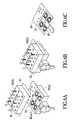
- FIG. 9( a )shows a perspective view of a semiconductor package after sawing without using the inventive leadframe carrier.
- FIG. 9( b )shows a perspective view of a semiconductor package after sawing using the inventive leadframe carrier.
- Embodiments of the inventionare directed to semiconductor packages and methods for making semiconductor packages. Embodiments of the invention can be applied to semiconductor packages with various pinouts such as 6, 8, etc. leads, while employing single sided molding technology. In some embodiments, the packages may be “single-sided” rather than semiconductor packages that are “double-sided”. Single-sided semiconductor packages have molding material at one side of the die, while double-sided packages have molding material at both sides of the die.
- Embodiments of the inventionhave a low package profile. Embodiments of the invention also provide a small package footprint, while increasing the die to package ratio for a given footprint, which is not possible for a wire-bonded type package. Also, in embodiments of the invention, the back side of the semiconductor die is exposed through the molding material in the package, thus improving heat dissipation to the underlying circuit substrate (as compared to a package where a molding material covers the back side).
- FIG. 1shows a flowchart illustrating an exemplary process flow according to an embodiment of the invention. Each step in the flowchart is described in further detail below.
- the leadframe structuremay be one of many leadframe structures in a leadframe carrier, which can be in the form of a strip. During processing, the leadframe structures may be present in a leadframe carrier if multiple leadframe structures are processed together.
- Each leadframe structurecan include a die attach region, and two or more leads. The leads extend away from the die attach region.
- a single lead frame structuremay include a gate lead structure with a gate attach region and a gate lead and a source lead structure with a plurality of source leads and a source attach region. The source lead structure and the gate lead structure are electrically isolated from each other in the semiconductor package that is eventually formed.
- the leadframe structuremay include a leadframe plating.
- a leadframe platingcomprises layers that are formed on a base metal of a leadframe structure prior to solder dispensing.
- a typical leadframe platingcomprises an adhesion sublayer, and a wettable/protective sublayer.
- an exemplary leadframe platingmay comprise at least a nickel sublayer and a palladium sublayer.
- the platingmay also comprise a gold sublayer as an outer, solder-wettable sublayer.
- the base metal of the leadframe structuremay comprise any suitable metal including copper or a copper alloy.
- solderis dispensed on the die attach region of the leadframe structure (step 10 ( b )).
- the soldermay be dispensed in an array on the die attach region of the leadframe structure.
- a dispenser with multiple nozzlesmay be used to dispense solder. If the semiconductor die comprises a vertical MOSFET, the dispensed solder may eventually be coupled to the source and gate regions of the MOSFET.
- a semiconductor diecan be attached to the die attach region of the leadframe structure (step 10 ( c )).
- the semiconductor diecomprises a vertical MOSFET
- the semiconductor diemay have at least one gate region and a gate pad, and at least one source region and a source pad at a first side.
- a drain regionmay be at the second side of the semiconductor die.
- Conductive structuressuch as high lead solder bumps may be attached to the at least one gate pad and at least one source pad.
- the conductive structurescan be attached to the leadframe structure through the previously dispensed solder, by flipping the bumped semiconductor die over and aligning the high lead solder bumps with the dispensed array of solder on the die attach region of the leadframe structure.
- Each high lead bump and solder combinationmay be characterized as a solder structure.
- the solder structures between the semiconductor die and the die attach region of the leadframe structureare subjected to a reflow process (step 10 ( d )).
- the reflowed solder structuresprovide a mechanical and an electrical connection between the leadframe structure and the semiconductor die.
- the soldermelts and solidifies, while the high lead solder bumps undergo minimal or no melting, so that they do not deform in a substantial manner. This keeps the semiconductor die and the die attach region of the leadframe structure spaced at a uniform distance, thus keeping the back side of the semiconductor die aligned with the ends of the leads of the leadframe structure.
- the solder that is chosenhas a melting temperature above the board mounting requirement, and below the melting point of the high-lead solder bumps on the semiconductor die.
- a molding materialis molded around at least the die attach region of each leadframe structure and the first surface of each semiconductor die (step 10 ( e )).
- the molding materialmay comprise an epoxy molding material.
- the molding processis preferably a film assisted molding process. Film assisted molding processes are described in further detail below.
- each leadframe structureAfter molding the molding material, the gate lead structure of each leadframe structure can be electrically isolated from its corresponding source lead structure by severing the electrical connection between them (step 10 ( f )). Then, the non-singulated semiconductor packages may be electrically tested (step 10 ( g )). Parametric testing is performed while the semiconductor packages are in the form of a strip. After electrical testing, the molded molding material in the semiconductor packages may be laser marked (step 10 ( h )).
- the semiconductor packages in the array of semiconductor packageare singulated (step 10 ( i )).
- a sawis used to separate the individual packages from other packages.
- Saw slotsmay be provided in a leadframe carrier to help guide the saw during singulation process and avoid mis-aligned cutting.
- a conventional tape and reel processmay be performed (step 10 ( j )).
- FIG. 2shows a cross-sectional view of a semiconductor package 100 mounted to a circuit substrate 34 .
- the circuit substrate 34may be a printed circuit board with one or more dielectric layers, and one or more conductive layers (not shown in FIG. 2 ).
- the circuit substrate 34 and the semiconductor package 100are coupled together via a number of reflowed solder paste deposits 32 ( a ), 32 ( b ), 32 ( c ).
- Each reflowed solder paste deposit 32 ( a ), 32 ( b ), 32 ( c )may comprise a solder with a low melting point.
- the semiconductor package 100comprises a leadframe structure 22 and a semiconductor die 30 attached to the leadframe structure 22 .
- An array of solder structures 36is between the semiconductor die 30 and the leadframe structure 22 .
- Each solder structurecomprises a solder bump 36 ( b ) and reflowed solder paste 36 ( a ).
- the array of solder structures 36results in smaller inductances than, for example, wire bonds.
- the semiconductor die 30has a first side 30 ( a ) and a second side 30 ( b ). If the semiconductor die comprises a vertical MOSFET, then the source region and the gate region (not shown) of the vertical MOSFET can be at the first side 30 ( a ) of the semiconductor die 30 and the drain region can be at the second side 30 ( b ) of the semiconductor die 30 .
- the second side 30 ( b )may be coated with gold or other solder-wettable material.
- the drain region of the MOSFET at the second side 30 ( b )would be coupled to the circuit substrate 34 via solder paste deposit 32 ( b ).
- the source region and the gate region of the MOSFETwould be coupled to the circuit substrate 34 via solder paste deposits 32 ( a ), 32 ( c ), which couple the ends of the leadframe structure 22 to the circuit substrate 34 .
- the semiconductor die in the semiconductor packagemay comprise a transistor such as a vertical power transistor.
- a transistorsuch as a vertical power transistor.
- Exemplary vertical power transistorsare described, for example, in U.S. Pat. Nos. 6,274,905, and 6,351,018, both of which are assigned to the same assignee as the present application, and both which are herein incorporated by reference in their entirety for all purposes.
- Vertical power transistorsinclude VDMOS transistors and vertical bipolar power transistors.
- a VDMOS transistoris a MOSFET (metal oxide semiconductor field effect transistor) that has two or more semiconductor regions formed by diffusion. It has a source region, a drain region, and a gate. The device is vertical in that the source region and the drain region are at opposite surfaces of the semiconductor die.
- MOSFETmetal oxide semiconductor field effect transistor
- the gatemay be a trenched gate structure or a planar gate structure, and is formed at the same surface as the source region. During operation, the current flow from the source region to the drain region in a VDMOS device is substantially perpendicular to the die surfaces.
- the transistors in the semiconductor diescan be bipolar transistors. In such embodiments, one side of the semiconductor die can have an emitter region and a base region. The other side of the die can have a collector region.
- LDMOSlateral diffused metal oxide semiconductor
- VDMOSlateral diffused metal oxide semiconductor
- LDMOSlateral diffused metal oxide semiconductor
- the cells in a VDMOSare smaller and denser than the cells in an LDMOS device, since the source region and the drain region in a VDMOS device are at opposite sides of the semiconductor die. Consequently, a VDMOS device can have a lower “on” resistance than an LDMOS device.
- VDMOS devicesgenerally exhibit higher gain and higher saturation current than LDMOS devices.
- the solder deposit 36 ( a )may comprise a eutectic solder.
- the eutectic temperature of an alloyis lower than the melting point of any of its individual constituents.
- the eutectic temperatureis the particular temperature at which the eutectic occurs.
- eutectic solder pastehas a composition of 63% tin (Sn) and 37% lead (Pb) (weight percentages), and has a eutectic temperature of 183° C.
- Each solder structure 36also comprises a solder bump 36 ( b ) or other conductive bump material that has a melting temperature greater than the melting temperature of the solder paste 36 ( a ).
- the solder bump 36 ( b )may comprise high lead solder.
- “high lead solder”may be a solder composition where the weight percentage of lead in the solder is greater than about 70% (e.g., 95Pb/5Sn) by weight.
- conductive columnse.g., conductive copper columns
- the melting temperatures of the soldercan be chosen as follows: mounting board solder paste 32 ( a )– 32 ( c ) ⁇ solder deposit 36 ( a ) ⁇ solder bumps 36 ( b ).
- the semiconductor package 100comprises a molding material 40 that covers the inner portion (including the die attach region) of the leadframe structure 22 , the plurality of solder structures 36 , and at least the first side 30 ( a ) of the semiconductor die 30 .
- the molding material 40also fills the spaces between the solder structures 36 .
- the bottom surface of the molding material 40is substantially co-planar with the ends of the leads of the leadframe structure 22 , and is also substantially co-planar with the second surface 30 ( b ) of the semiconductor die 30 .
- the ends of the leads of the leadframe structure 22extend laterally away from the molding material 40 .
- the illustrated semiconductor package 100has a low profile and is thin.
- the molding material 40comprises an epoxy molding material.
- the epoxy molding materialpreferably has the following properties: (a) low thermal expansion (a low CTE), (b) fine filler size (for better flow distribution of the molding material in between small spaces, thus reducing the likelihood of forming voids in the formed semiconductor package), (c) a glass transition temperature of about 146° C., (d) a 10 second Ram Follower gel time at 175° C., and e) high adhesion strength to pre-plated leadframe structures.
- a preferred epoxy molding materialcan be Plaskon AMC-2RD molding compound, which is commercially available from Cookson Semiconductor Packaging Materials, of Singapore.
- This epoxy molding materialhas a low coefficient of thermal expansion, does not require a post mold cure, and is useful for high productivity processing. It also has good adhesion to pre-plated leadframes, thereby minimizing the likelihood of delamination between the molding material and the leadframe structure. The epoxy molding compound flows well and minimizes the formation of any gaps in the molding material. Other data and characteristics pertinent to this molding material are provided in U.S. Provisional Application No. 60/373,370, filed on Apr. 16, 2002, and U.S. Provisional Application No. 60/376,812, filed on Apr. 29, 2002.
- FIG. 3( a )shows a leadframe structure 22 according to an embodiment of the invention.
- the leadframe structure 22comprises a gate lead structure 22 ( a ) including a gate attach region 22 ( a )- 1 and a gate lead 22 ( a )- 2 , and a source lead structure 22 ( b ) including a source attach region 22 ( b )- 1 and five source leads 22 ( b )- 2 .
- the gate attach region 22 ( a )- 1 and the source attach region 22 ( b )- 1can form the die attach region 21 of the leadframe structure 22 , where the semiconductor die (not shown) is attached.
- the die attach region 21is “downset” with respect to the ends of the gate lead 22 ( a )- 2 and the source leads 22 ( b )- 2 .
- the leadframe structure 22includes a layer of metal plating (not shown) if desired.
- a layer of metal platingmay comprise an adhesion sublayer layer such as nickel or chromium, a conductive sublayer such as copper or palladium, and/or an oxidation resistant layer such as gold.
- the base metal of the leadframe structure 22may comprise a metal such as copper or a copper alloy.
- the leadframe structure 22may be formed in any suitable manner.
- the base metal structure of the leadframe structure 22may comprise copper, and may be formed by stamping or etching a copper sheet.
- a layer of metal platingmay be formed on the base metal structure by processes such as electroless plating, sputtering, or electroplating.
- a pre-plated leadframeadvantageously eliminates post plating processes, and provides wettable surfaces for solder paste on the conductive lands of a circuit substrate.
- An aperture 23is in the die attach region 21 .
- the aperture 23 in this exampleis in the form of an elongated slot.
- the aperture 23is in the form of an elongated slot, other aperture shapes (e.g., circular apertures, square apertures, etc.) are possible.
- the aperture 23may be formed in the leadframe structure 22 by any suitable method including photolithography followed by etching, and stamping.
- the die attach region 21 of the leadframe structure 22may comprise a number of dimples in it to improve adhesion to the molding material.
- Dimplesmay be formed in the die attach region 21 of the leadframe structure 22 using a process such as partial etching (using photolithography and a wet or dry etching process so that only part of the thickness of the die attach region 21 is etched).
- the molding material(not shown) may flow over and attach to the dimples, thus improving the bond between the molding material and the leadframe structure.
- the aperture 23 in the die attach region 21provides a passageway for a molding compound to flow through.
- the aperture 23improves the molding material flow between the semiconductor die and the die attach region 21 , thus eliminating package voids.
- the molding compound“locks” onto the leadframe structure 22 , thus decreasing the likelihood of delamination between the leadframe structure and the molding material (e.g., the locking feature helps hold the package together during stress-inducing processes such as a 3 ⁇ reflow process).
- the molding materialfills the spaces between and around the die, and the leadframe structure, the molding material secures the die and solder structures to the leadframe structure, thus reducing subsequent stresses caused by further processing or the end use of the semiconductor package.
- FIGS. 3( b ) and 3 ( c )Another feature of the leadframe structure 22 is shown in FIGS. 3( b ) and 3 ( c ).
- a number of depressions 24are formed at edge regions of the die attach region 21 , proximate to the inner portions of the leads 22 ( a )- 2 , 22 ( b )- 2 and is distal to the outer portions of the leads.
- a depression 24is formed at the edge of the gate attach region 22 ( a )- 1 of the gate lead structure 22 ( a ), and is proximate to the inner portion 22 ( a )- 2 ′ of the gate lead 22 ( a )- 2 .
- the outer portion 22 ( a )- 2 ′′ of the gate lead 22 ( a )extends away from the die attach region 21 and is distal to the depression 24 .
- gate attach region with a depressionmay be referred to as a “coined gate pad”.
- the depressions 24 in the leadframe structure 22may have any suitable width and depth.
- each depression 24may be less than half the thickness of the die attach region 21 of the leadframe structure 22 .
- Each depression 24may have a length about equal to the width the lead 22 ( a )- 2 , 22 ( b )- 2 that corresponds to it.
- the depressions 24 in the leadframe structure 22may be formed using any suitable process. For example, in some embodiments, stamping or a half-etching process can be used. A leadframe structure without depressions could be patterned with photoresist, and then partially etched in those areas where the depressions are to be formed. Photolithography and etching processes are well known to those of ordinary skill in the art.
- depressions 24 in the die attach region 21 of the leadframe structure 22has a number of advantages.
- the depressions 24restrict the flow of solder as a result of capillary action during reflow, thereby restricting the flow of the solder deposit towards the lead bends. By restricting the flow of solder towards the lead bends, the likelihood of die edge shorting is reduced.
- the semiconductor die 30moves, because of the capillary flow of the solder deposit 36 ( a ) towards the bent lead 22 ( b )- 2 during the re-melting of the solder deposit 36 ( a ).
- the semiconductor die 30also moves in the direction of the arrow 92 along with the moving solder deposit 36 ( a ), and the edge of the semiconductor die 30 can contact the lead 22 ( b )- 2 at the point 90 , thus short circuiting the semiconductor die 30 .
- FIG. 3( d )shows that the die attach region does not have depressions.
- the solder deposit 36 ( a )flows into the depressions 24 , thus inhibiting the side-to-side movement of the semiconductor die 30 during the re-melting of the solder deposit 36 ( a ).
- the semiconductor die 30remains between opposite leads of the leadframe structure 22 .
- the depressions 24help to prevent die edge shorting between the edge of the semiconductor die 30 and the bent leads of the leadframe structure 22 .
- FIG. 4( a )shows an SEM (scanning electron microscope) photo of a cross-section of a scalloped-shaped source pad 220 in a semiconductor die.
- the semiconductor dieincludes a number of trenches 222 and BPSG (borophosphosilicate glass) domes 206 ( a ) over the trenches 222 .
- the trenches 222may be trenched gates and the domes 206 ( a ) isolate the trenched gates from the source pad 220 .
- a barrier layer metal 216 ( a ) in the form of a thin white layercan be viewed through the SEM.
- the source pad 220which is formed on top of the barrier metal layer 216 ( a ) has an upper surface that is uneven and scallop-shaped.
- an underbump metallurgy layer 204 ( a )is deposited on the source pad 220 , and a high lead solder bump 202 ( a ) is on the underbump metallurgy layer 204 ( a ).
- dome shaped structureson top of the gate trenches. This is done in order to isolate electrically the gate trenches from the rest of the source area.
- These “dome” structuresserve as the base wherein a barrier metal layer and an aluminum layer are deposited.
- the deposited metal layersfollow the contour or topography of the dome structures, thus forming a scalloped shaped source pad.
- the shape of the source padhelps to adhere the source pad to the underbump metallurgy layer.
- FIG. 4( b )shows a cross-section of an aluminum gate bond pad 208 .
- a polysilicon layer 210has a number of BPSG humps 206 .
- a thin barrier metal layer portion (e.g., titanium) 216 ( b )is over the BPSG humps 206 .
- a portion of the barrier metalreacts with the polysilicon layer to form a thin interlayer of silicide (titanium silicide) at 220 .
- This silicide layerholds the barrier metal layer 216 ( b ) and the polysilicon layer 210 together thereby increasing the adhesion strength of the barrier metal layer 216 ( b ).
- a gate pad metal layer 208such as an aluminum layer is also deposited over the barrier metal layer 216 ( b ).
- gate contact areas to the BPSGare retained, so as to have stress-relievers whenever the structure experiences shear stresses during processing and during end user applications.
- the gate pad metal(which may be an aluminum pad) 208 is formed on the BPSG humps 206 , the resulting upper surface of the gate pad metal 208 is uneven.
- the underbump metallurgy layer 204 ( b )adheres tightly to the upper surface of the gate pad metal 208 , and a high lead solder bump 202 ( b ) is on the underbump metallurgy layer 204 ( b ).
- the uneven gate pad metal 208 surfaceprovides improved bump attachment integrity by providing good pad topography and an increased attach area.
- 5 ⁇ 5 square micron holesare formed in a continuous BPSG layer.
- the holesmay be formed using an etching process.
- the topographycan change depending on how the BPSG layer is etched.
- FIG. 5( a )illustrates the particular solder structures that are used in embodiments of the invention.
- FIG. 5( a )shows a semiconductor die 30 attached to a leadframe structure 22 , after the semiconductor die 30 that is bumped with the solder bumps 36 ( b ) is flipped over and mounted to discrete deposits of solder deposit 36 ( a ) on the die attach region of the leadframe structure 22 , but before reflowing the solder deposit 36 ( a ).
- the solder bumps 36 ( b )Prior to attaching the bumped semiconductor die 30 to the leadframe structure 22 , the solder bumps 36 ( b ) can be formed on the bond pads of the semiconductor die 30 .
- the solder bumps 36 ( b )can be formed by, for example, a pick and place process, a dispensing process, a ball attach process, etc.
- the solder bumps 36 ( b )may comprise high lead solder (e.g., 95Pb/5Sn), while the solder deposit 36 ( a ) may comprise an ordinary solder such as 63Pb/37Sn. As shown in FIG. 5( a ), the vertical offset D of the second surface 30 ( b ) of the semiconductor die 30 to the ends of the leads may be limited to a maximum of 70 microns.
- Each combination of solder deposit 36 ( a ) (e.g., before or after reflow) and a corresponding solder bump 36 ( b )may be referred to as a solder structure.
- the discrete solder deposit 36 ( a )may be deposited on the die attach region of the leadframe structure 22 using a multi-nozzle dispense tool to create consistent solder dot arrays.
- the solder deposit 36 ( a )can be chosen such that its melting point is above the board mounting requirement, and is below the melting points of the solder in the solder bumps 36 ( b ).
- the second surface 30 ( b ) of the semiconductor die 30 and the ends of the leads of the leadframe structure 22may be substantially co-planar as the solder deposit 36 ( a ) melts and then re-solidifies. Because of the high lead content in the high lead solder bumps 36 ( b ), the high lead solder bumps 36 ( b ) do not collapse. In this “no collapse” process, the standoff of the die is maintained, since the solder bumps 36 ( b ) do not re-melt during solder paste reflow. This process makes it possible to control the die to lead co-planarity of less than 70 microns and also makes it possible to avoid die tilting which can cause cracks in the die.
- soldering fluxis used instead of a solder paste to remove oxides from the solder bump surfaces prior to re-melting.
- a tilted dieresults from the full collapse process. The tilted die eventually results in die cracks after molding (see e.g., the crack 55 in FIG. 5) . Since the semiconductor die does not tilt when using high lead solder or other non-deformable conductive structure, the resulting semiconductor die does not crack in the final semiconductor package.
- the second surface 30 ( b ) of the semiconductor die 30is not co-planar with the ends of the leads of the leadframe structure 22 , then the second surface 30 ( b ) and the ends of the leads may not make good contact to the conductive lands on a circuit substrate.
- a molding materialis molded around the semiconductor die and the die attach region of the leadframe structure.
- a film assisted molding processis used.
- a filmis used between molding dies of a mold tool.
- the filmserves as a cushion for the semiconductor die during molding, thus absorbing the stress and preventing die cracks.
- the use of a filmalso allows a smaller clamping force to be used.
- the filmmay be an adhesive-free film, which protects the exposed die back side and the leads from mold bleed that can prevent solderability during board mounting.
- An exemplary filmis a fluoropolymer film that has a matted surface finish on one side and a glossy finish on the other side. It is sold under the tradename AFLEX 50KN. Other commercially available mold release films could be used in other embodiments.
- a film 82is mounted in between the open top and bottom mold dies 80 ( a ), 80 ( b ) in a molding apparatus. Then, a leadframe carrier 84 in the form of a strip is loaded on the bottom mold die 80 ( a ) and is positioned such that the exposed second surface of the semiconductor die 30 is beneath the film 82 and the semiconductor die is in a mold cavity 80 ( a )- 1 in the bottom mold die 80 ( a ). The film 82 is then suctioned to the top mold die 80 ( b ) to hold it flat against the inner surface thereof (air removal is shown by the arrow 58 ). Pellets (not shown) of the molding material are then loaded on the molding apparatus.
- the bottom mold die 80 ( a )then moves toward the top mold die 80 ( b ) and clamps the leadframe carrier 84 and the film 82 together as shown in FIG. 6( b ).
- the film 82is pressed down on the die back instead of directly contacting the top mold die 80 ( b ) (which may be made of metal), thus absorbing a certain amount of stress, which could translate into die cracking during clamping.
- the molding materialis then melted and is transferred from the loading station to the individual mold cavities. During this state, the film 82 acts as a barrier to prevent the molding material from depositing on the exposed die back side and the bottom surfaces of the leads, thus ensuring that the back sides of the semiconductor dies and the leads are free of molding material (as shown in FIG.
- each semiconductor die 30has a molded molding material 40 around it.
- the bottom mold die 80 ( a )moves down to open the two mold dies 80 ( a ), 80 ( b ) and ejects the molded strip upon reaching the home position as shown in FIG. 6( a ). No mold flashes were noted during actual testing of the top surfaces of the dies.
- the singulation processis preferably a tapeless singulation process.
- a tapeless singulation processuses a metal saw jig instead of commonly used dicing tapes to hold the semiconductor packages in place during sawing.
- a strip of molded packagescan be loaded onto a jig with recesses that are arranged in a layout similar to the layout of the molded packages in the leadframe carrier, while the back sides of the semiconductor die face upward.
- the leadframe carrier orientationis chosen to minimize vertical burr formation in the direction of the flat side of the package (which can cause mounting problems). The recesses and vacuum hold the molded packages in place during sawing.
- the tapeless singulation processhas advantages over conventional singulation processes that use adhesive tapes.
- dicing tapesare discarded after every use.
- the jigis reusable. Accordingly, embodiments of the invention are cost effective.
- a leadframe carrier 84 including a number of semiconductor package unitsis mounted onto a metal saw jig 102 .
- Each package unitincludes a semiconductor die 30 , and a molding material 40 as previously discussed.
- Every semiconductor package unit in the leadframe carrier 84is held to the jig 102 by vacuum suction. Holes 108 in the leadframe carrier 84 expose the top surface of the jig 102 .
- the vacuum suction provided by the jig 102ensures that there is no movement of the leadframe carrier 84 , which could cause jagged edges or burrs on the package leads after sawing.
- the individual semiconductor package unitsare then singulated by cutting the leadframe carrier 84 with a saw 110 as shown in FIG. 7 .
- Saw slots 104are formed in the leadframe carrier 84 .
- Fiducials 106guide the saw 110 as the saw 110 passes through the leadframe carrier 84 in the direction shown by the arrow 112 .
- a metal bonded or a nickel bonded bladeis used when a copper leadframe carrier is being sawn.
- Fiducials 106may be formed in the leadframe carrier 84 by etching, stamping, etc. After singulation, the saw jig 102 with the singulated package units can pass to a pick and place station for sorting and then final packaging. For example, the packages may be optionally washed and dried.
- FIG. 9( a )shows a semiconductor package where misaligned cutting occurred when fiducials were not used
- FIG. 9( b )shows a semiconductor package where sawing was performed using a carrier with fiducials.
- FIG. 9( a )shows leads on one side of the semiconductor package that are shorter than the leads on the other side.
- FIG. 9( b )shows leads on opposite sides of the semiconductor package being substantially equal in length.
- tapesneed not be used. This eliminates the amount of adhesive residue on the formed semiconductor packages.
- tapecould be used to hold the leadframe carrier 84 instead of a vacuum jig 102 .
- tape adhesive substancescan remain on the surface of a semiconductor die or leads after removing the tape, thus contaminating the die surfaces and the leads, which need to be soldered to a circuit board.
- tape residue 114 on the back side of the semiconductor package shown in FIG. 8can inhibit bonding.
- sawing the leadframe carrier to singulate the semiconductor packageshas advantages over, for example, punching them.
- Blade sawinginduces the least amount of stress to the lead and package, so that the likelihood of potential delamination is greatly reduced.
- a mechanical singulation processsuch as traditional punch and die systems are used to punch out semiconductor packages from a leadframe strip to singulate them.
Landscapes
- Physics & Mathematics (AREA)
- Condensed Matter Physics & Semiconductors (AREA)
- General Physics & Mathematics (AREA)
- Engineering & Computer Science (AREA)
- Computer Hardware Design (AREA)
- Microelectronics & Electronic Packaging (AREA)
- Power Engineering (AREA)
- Lead Frames For Integrated Circuits (AREA)
- Structures Or Materials For Encapsulating Or Coating Semiconductor Devices Or Solid State Devices (AREA)
Abstract
Description
Claims (12)
Priority Applications (3)
| Application Number | Priority Date | Filing Date | Title |
|---|---|---|---|
| US10/413,668US7122884B2 (en) | 2002-04-16 | 2003-04-14 | Robust leaded molded packages and methods for forming the same |
| US11/446,342US7560311B2 (en) | 2002-04-16 | 2006-06-01 | Robust leaded molded packages and methods for forming the same |
| US12/479,442US7906837B2 (en) | 2002-04-16 | 2009-06-05 | Robust leaded molded packages and methods for forming the same |
Applications Claiming Priority (3)
| Application Number | Priority Date | Filing Date | Title |
|---|---|---|---|
| US37337002P | 2002-04-16 | 2002-04-16 | |
| US37681202P | 2002-04-29 | 2002-04-29 | |
| US10/413,668US7122884B2 (en) | 2002-04-16 | 2003-04-14 | Robust leaded molded packages and methods for forming the same |
Related Child Applications (1)
| Application Number | Title | Priority Date | Filing Date |
|---|---|---|---|
| US11/446,342DivisionUS7560311B2 (en) | 2002-04-16 | 2006-06-01 | Robust leaded molded packages and methods for forming the same |
Publications (2)
| Publication Number | Publication Date |
|---|---|
| US20030193080A1 US20030193080A1 (en) | 2003-10-16 |
| US7122884B2true US7122884B2 (en) | 2006-10-17 |
Family
ID=28795022
Family Applications (3)
| Application Number | Title | Priority Date | Filing Date |
|---|---|---|---|
| US10/413,668Expired - LifetimeUS7122884B2 (en) | 2002-04-16 | 2003-04-14 | Robust leaded molded packages and methods for forming the same |
| US11/446,342Expired - LifetimeUS7560311B2 (en) | 2002-04-16 | 2006-06-01 | Robust leaded molded packages and methods for forming the same |
| US12/479,442Expired - LifetimeUS7906837B2 (en) | 2002-04-16 | 2009-06-05 | Robust leaded molded packages and methods for forming the same |
Family Applications After (2)
| Application Number | Title | Priority Date | Filing Date |
|---|---|---|---|
| US11/446,342Expired - LifetimeUS7560311B2 (en) | 2002-04-16 | 2006-06-01 | Robust leaded molded packages and methods for forming the same |
| US12/479,442Expired - LifetimeUS7906837B2 (en) | 2002-04-16 | 2009-06-05 | Robust leaded molded packages and methods for forming the same |
Country Status (1)
| Country | Link |
|---|---|
| US (3) | US7122884B2 (en) |
Cited By (56)
| Publication number | Priority date | Publication date | Assignee | Title |
|---|---|---|---|---|
| US20060180904A1 (en)* | 2005-02-14 | 2006-08-17 | Stats Chippac Ltd. | Non-leaded integrated circuit package system |
| US20060292747A1 (en)* | 2005-06-27 | 2006-12-28 | Loh Ban P | Top-surface-mount power light emitter with integral heat sink |
| US20070015316A1 (en)* | 2005-07-12 | 2007-01-18 | Madrid Ruben P | Folded frame carrier for MOSFET BGA |
| US20070187807A1 (en)* | 2006-02-13 | 2007-08-16 | Jeongil Lee | Multi-chip module for battery power control |
| US20080054417A1 (en)* | 2006-08-29 | 2008-03-06 | Sangdo Lee | Semiconductor die package including stacked dice and heat sink structures |
| US20080157321A1 (en)* | 2006-12-30 | 2008-07-03 | Zigmund Ramirez Camacho | Stackable integrated circuit package system with recess |
| US20080173991A1 (en)* | 2007-01-24 | 2008-07-24 | Erwin Victor Cruz | Pre-molded clip structure |
| US20080185696A1 (en)* | 2007-02-05 | 2008-08-07 | Ruben Madrid | Semiconductor die package including leadframe with die attach pad with folded edge |
| US20080203559A1 (en)* | 2007-02-28 | 2008-08-28 | Lee Keun-Hyuk | Power device package and semiconductor package mold for fabricating the same |
| US20080224285A1 (en)* | 2007-03-12 | 2008-09-18 | Lim Seung-Won | Power module having stacked flip-chip and method of fabricating the power module |
| US20080237829A1 (en)* | 2006-12-07 | 2008-10-02 | Chuan Cheah | High current lead electrode for semiconductor device |
| US20080251739A1 (en)* | 2007-04-13 | 2008-10-16 | Yoon Hwa Choi | Optical coupler package |
| US20080258272A1 (en)* | 2007-04-19 | 2008-10-23 | Lay Yeap Lim | Etched leadframe structure |
| US20080290482A1 (en)* | 2007-05-25 | 2008-11-27 | National Semiconductor Corporation | Method of packaging integrated circuits |
| US20090008775A1 (en)* | 2007-07-05 | 2009-01-08 | Nec Electronics Corporation | Semiconductor device with welded leads and method of manufacturing the same |
| US20090057852A1 (en)* | 2007-08-27 | 2009-03-05 | Madrid Ruben P | Thermally enhanced thin semiconductor package |
| US20090057854A1 (en)* | 2007-08-28 | 2009-03-05 | Gomez Jocel P | Self locking and aligning clip structure for semiconductor die package |
| US20090057855A1 (en)* | 2007-08-30 | 2009-03-05 | Maria Clemens Quinones | Semiconductor die package including stand off structures |
| US20090140266A1 (en)* | 2007-11-30 | 2009-06-04 | Yong Liu | Package including oriented devices |
| US20090140179A1 (en)* | 2007-11-30 | 2009-06-04 | Yong Liu | Semiconductor die packages suitable for optoelectronic applications having clip attach structures for angled mounting of dice |
| US20090146284A1 (en)* | 2007-12-06 | 2009-06-11 | Kim Ji-Hwan | Molded Leadless Packages and Assemblies Having Stacked Molded Leadless Packages |
| US20090160036A1 (en)* | 2007-12-19 | 2009-06-25 | David Grey | Package with multiple dies |
| US20090166826A1 (en)* | 2007-12-27 | 2009-07-02 | Janducayan Omar A | Lead frame die attach paddles with sloped walls and backside grooves suitable for leadless packages |
| US20090174048A1 (en)* | 2008-01-09 | 2009-07-09 | Yong Liu | Die package including substrate with molded device |
| US20090174044A1 (en)* | 2007-12-13 | 2009-07-09 | Eom Joo-Yang | Multi-chip package |
| US20090179313A1 (en)* | 2008-01-10 | 2009-07-16 | Maria Clemens Quinones | Flex clip connector for semiconductor device |
| US20090194857A1 (en)* | 2008-02-01 | 2009-08-06 | Yong Liu | Thin Compact Semiconductor Die Packages Suitable for Smart-Power Modules, Methods of Making the Same, and Systems Using the Same |
| US20090194856A1 (en)* | 2008-02-06 | 2009-08-06 | Gomez Jocel P | Molded package assembly |
| US20090218666A1 (en)* | 2008-02-28 | 2009-09-03 | Yang Gwi-Gyeon | Power device package and method of fabricating the same |
| US20090230536A1 (en)* | 2008-03-12 | 2009-09-17 | Yong Liu | Semiconductor die package including multiple semiconductor dice |
| US20090230537A1 (en)* | 2008-03-12 | 2009-09-17 | Yong Liu | Semiconductor die package including embedded flip chip |
| US20090236714A1 (en)* | 2002-04-16 | 2009-09-24 | Elsie Agdon Cabahug | Robust leaded molded packages and methods for forming the same |
| US20090243079A1 (en)* | 2008-03-31 | 2009-10-01 | Lim Seung-Won | Semiconductor device package |
| US20090278241A1 (en)* | 2008-05-08 | 2009-11-12 | Yong Liu | Semiconductor die package including die stacked on premolded substrate including die |
| US20090317948A1 (en)* | 2008-06-24 | 2009-12-24 | Renesas Technology Corp. | Method for manufacturing a semiconductor integrated circuit device |
| US20100052119A1 (en)* | 2008-08-28 | 2010-03-04 | Yong Liu | Molded Ultra Thin Semiconductor Die Packages, Systems Using the Same, and Methods of Making the Same |
| US20100072590A1 (en)* | 2008-09-22 | 2010-03-25 | Yong Liu | Stacking Quad Pre-Molded Component Packages, Systems Using the Same, and Methods of Making the Same |
| US20100123257A1 (en)* | 2008-11-14 | 2010-05-20 | Yong Liu | Flexible and Stackable Semiconductor Die Packages, Systems Using the Same, and Methods of Making the Same |
| US7737548B2 (en) | 2007-08-29 | 2010-06-15 | Fairchild Semiconductor Corporation | Semiconductor die package including heat sinks |
| US20100148346A1 (en)* | 2008-12-12 | 2010-06-17 | Quinones Maria Clemens Y | Semiconductor die package including low stress configuration |
| US20100193921A1 (en)* | 2009-02-05 | 2010-08-05 | Jereza Armand Vincent C | Semiconductor die package and method for making the same |
| US7791084B2 (en) | 2008-01-09 | 2010-09-07 | Fairchild Semiconductor Corporation | Package with overlapping devices |
| US20100301372A1 (en)* | 2003-05-27 | 2010-12-02 | Cree, Inc. | Power surface mount light emitting die package |
| US7973393B2 (en) | 2009-02-04 | 2011-07-05 | Fairchild Semiconductor Corporation | Stacked micro optocouplers and methods of making the same |
| CN102163562A (en)* | 2011-03-18 | 2011-08-24 | 聚信科技有限公司 | Method for mounting power semiconductor element and synchronous buck converter |
| US20110285025A1 (en)* | 2010-05-24 | 2011-11-24 | Yuping Gong | Wafer Level Chip Scale Package Method Using Clip Array |
| US8163601B2 (en)* | 2010-05-24 | 2012-04-24 | Alpha & Omega Semiconductor, Inc. | Chip-exposed semiconductor device and its packaging method |
| US8193618B2 (en) | 2008-12-12 | 2012-06-05 | Fairchild Semiconductor Corporation | Semiconductor die package with clip interconnection |
| US8308331B2 (en) | 2005-06-14 | 2012-11-13 | Cree, Inc. | LED backlighting for displays |
| US8421204B2 (en) | 2011-05-18 | 2013-04-16 | Fairchild Semiconductor Corporation | Embedded semiconductor power modules and packages |
| US8530915B2 (en) | 2002-09-04 | 2013-09-10 | Cree, Inc. | Power surface mount light emitting die package |
| US8603862B2 (en) | 2010-05-14 | 2013-12-10 | International Business Machines Corporation | Precise-aligned lock-and-key bonding structures |
| TWI456670B (en)* | 2010-09-07 | 2014-10-11 | Alpha & Omega Semiconductor Cayman Ltd | A method of semiconductor package with die exposure |
| US9536800B2 (en) | 2013-12-07 | 2017-01-03 | Fairchild Semiconductor Corporation | Packaged semiconductor devices and methods of manufacturing |
| US11562949B2 (en)* | 2020-06-17 | 2023-01-24 | Texas Instruments Incorporated | Semiconductor package including undermounted die with exposed backside metal |
| US11916090B2 (en) | 2020-07-01 | 2024-02-27 | Stmicroelectronics, Inc. | Tapeless leadframe package with exposed integrated circuit die |
Families Citing this family (50)
| Publication number | Priority date | Publication date | Assignee | Title |
|---|---|---|---|---|
| US7264378B2 (en) | 2002-09-04 | 2007-09-04 | Cree, Inc. | Power surface mount light emitting die package |
| US6943434B2 (en)* | 2002-10-03 | 2005-09-13 | Fairchild Semiconductor Corporation | Method for maintaining solder thickness in flipchip attach packaging processes |
| US7692206B2 (en)* | 2002-12-06 | 2010-04-06 | Cree, Inc. | Composite leadframe LED package and method of making the same |
| US6897486B2 (en) | 2002-12-06 | 2005-05-24 | Ban P. Loh | LED package die having a small footprint |
| US7217594B2 (en)* | 2003-02-11 | 2007-05-15 | Fairchild Semiconductor Corporation | Alternative flip chip in leaded molded package design and method for manufacture |
| US7109064B2 (en)* | 2003-12-08 | 2006-09-19 | Semiconductor Components Industries, L.L.C. | Method of forming a semiconductor package and leadframe therefor |
| US7280288B2 (en) | 2004-06-04 | 2007-10-09 | Cree, Inc. | Composite optical lens with an integrated reflector |
| US7456499B2 (en) | 2004-06-04 | 2008-11-25 | Cree, Inc. | Power light emitting die package with reflecting lens and the method of making the same |
| KR100634379B1 (en)* | 2004-07-14 | 2006-10-16 | 삼성전자주식회사 | Semiconductor package |
| JP4456503B2 (en)* | 2004-12-24 | 2010-04-28 | 富士通メディアデバイス株式会社 | Manufacturing method of electronic parts |
| US7256479B2 (en)* | 2005-01-13 | 2007-08-14 | Fairchild Semiconductor Corporation | Method to manufacture a universal footprint for a package with exposed chip |
| DE102005009795A1 (en)* | 2005-03-03 | 2006-09-14 | Wago Verwaltungsgesellschaft Mbh | Microprocessor system for machine control in safety certifiable applications |
| US7285849B2 (en)* | 2005-11-18 | 2007-10-23 | Fairchild Semiconductor Corporation | Semiconductor die package using leadframe and clip and method of manufacturing |
| SG133425A1 (en)* | 2005-12-15 | 2007-07-30 | Aem Tech Engineers Pte Ltd | Semiconductor package and method of fabrication thereof |
| WO2008056195A1 (en)* | 2006-11-06 | 2008-05-15 | Infineon Technologies Ag | A multi-chip package |
| KR100813625B1 (en)* | 2006-11-15 | 2008-03-14 | 삼성전자주식회사 | Semiconductor device package |
| WO2008088291A1 (en)* | 2007-01-16 | 2008-07-24 | Infineon Technologies Ag | Method of semiconductor packaging and/or a semiconductor package |
| US7863738B2 (en)* | 2007-05-16 | 2011-01-04 | Texas Instruments Incorporated | Apparatus for connecting integrated circuit chip to power and ground circuits |
| US20090079082A1 (en)* | 2007-09-24 | 2009-03-26 | Yong Liu | Bonding pad structure allowing wire bonding over an active area in a semiconductor die and method of manufacturing same |
| US7965126B2 (en) | 2008-02-12 | 2011-06-21 | Transphorm Inc. | Bridge circuits and their components |
| US20090283137A1 (en)* | 2008-05-15 | 2009-11-19 | Steven Thomas Croft | Solar-cell module with in-laminate diodes and external-connection mechanisms mounted to respective edge regions |
| US8289065B2 (en) | 2008-09-23 | 2012-10-16 | Transphorm Inc. | Inductive load power switching circuits |
| US9059351B2 (en) | 2008-11-04 | 2015-06-16 | Apollo Precision (Fujian) Limited | Integrated diode assemblies for photovoltaic modules |
| US8586857B2 (en)* | 2008-11-04 | 2013-11-19 | Miasole | Combined diode, lead assembly incorporating an expansion joint |
| US20100149773A1 (en)* | 2008-12-17 | 2010-06-17 | Mohd Hanafi Mohd Said | Integrated circuit packages having shared die-to-die contacts and methods to manufacture the same |
| US8138529B2 (en) | 2009-11-02 | 2012-03-20 | Transphorm Inc. | Package configurations for low EMI circuits |
| US8203200B2 (en)* | 2009-11-25 | 2012-06-19 | Miasole | Diode leadframe for solar module assembly |
| US8486757B2 (en)* | 2009-11-25 | 2013-07-16 | Infineon Technologies Ag | Semiconductor device and method of packaging a semiconductor device with a clip |
| JP4929382B2 (en)* | 2010-07-13 | 2012-05-09 | 株式会社東芝 | Electronic component structure and electronic device |
| JP5822468B2 (en)* | 2011-01-11 | 2015-11-24 | ローム株式会社 | Semiconductor device |
| JP5940257B2 (en)* | 2011-08-01 | 2016-06-29 | 株式会社三井ハイテック | Lead frame, lead frame manufacturing method, and semiconductor device using the same |
| CN103035631B (en)* | 2011-09-28 | 2015-07-29 | 万国半导体(开曼)股份有限公司 | Combine the semiconductor device and manufacture method thereof that encapsulate high-end and low side chip |
| US8648643B2 (en) | 2012-02-24 | 2014-02-11 | Transphorm Inc. | Semiconductor power modules and devices |
| TWI460837B (en)* | 2012-06-19 | 2014-11-11 | Chipbond Technology Corp | Semiconductor package and lead frame thereof |
| US9059076B2 (en) | 2013-04-01 | 2015-06-16 | Transphorm Inc. | Gate drivers for circuits based on semiconductor devices |
| US9537425B2 (en) | 2013-07-09 | 2017-01-03 | Transphorm Inc. | Multilevel inverters and their components |
| US9543940B2 (en) | 2014-07-03 | 2017-01-10 | Transphorm Inc. | Switching circuits having ferrite beads |
| US9590494B1 (en) | 2014-07-17 | 2017-03-07 | Transphorm Inc. | Bridgeless power factor correction circuits |
| CN104392977B (en)* | 2014-10-16 | 2017-04-12 | 东莞市柏尔电子科技有限公司 | Packaging triode |
| WO2016149146A1 (en) | 2015-03-13 | 2016-09-22 | Transphorm, Inc. | Paralleling of switching devices for high power circuits |
| USD793844S1 (en)* | 2015-07-23 | 2017-08-08 | Ceko Co., Ltd. | Carrier jig |
| USD793845S1 (en)* | 2015-07-28 | 2017-08-08 | Ceko Co., Ltd. | Carrier jig |
| US10319648B2 (en) | 2017-04-17 | 2019-06-11 | Transphorm Inc. | Conditions for burn-in of high power semiconductors |
| EP3921171B1 (en) | 2019-02-06 | 2025-03-26 | Hewlett-Packard Development Company, L.P. | Fluid ejection device with a carrier having a slot |
| TWI728318B (en)* | 2019-02-27 | 2021-05-21 | 力成科技股份有限公司 | System in package structure |
| US12424524B2 (en)* | 2020-10-13 | 2025-09-23 | Amkor Technology Singapore Holding Pte. Ltd. | Semiconductor devices and methods of manufacturing semiconductor devices |
| CN217521996U (en)* | 2020-12-17 | 2022-09-30 | 意法半导体股份有限公司 | Semiconductor device with a plurality of transistors |
| CN114649221A (en)* | 2020-12-17 | 2022-06-21 | 意法半导体股份有限公司 | Method of manufacturing a semiconductor device and corresponding semiconductor device |
| DE102021125780A1 (en) | 2021-10-05 | 2023-04-06 | Infineon Technologies Ag | SEGMENTED LEADFRAME FOR FLIP-CHIP ATTACHMENT OF A SEMICONDUCTOR CHIP WITH PREVENTION OF THE CHIP'S TILTING |
| TWI784778B (en)* | 2021-11-01 | 2022-11-21 | 芯灃科技有限公司 | Diode package structure and method of manufacturing the same |
Citations (34)
| Publication number | Priority date | Publication date | Assignee | Title |
|---|---|---|---|---|
| US5540378A (en)* | 1993-09-27 | 1996-07-30 | Olin Corporation | Method for the assembly of an electronic package |
| US5637916A (en) | 1996-02-02 | 1997-06-10 | National Semiconductor Corporation | Carrier based IC packaging arrangement |
| US5789809A (en) | 1995-08-22 | 1998-08-04 | National Semiconductor Corporation | Thermally enhanced micro-ball grid array package |
| US6023080A (en)* | 1997-02-12 | 2000-02-08 | Kabushiki Kaisha Toshiba | Input/output connection structure of a semiconductor device |
| US6133634A (en) | 1998-08-05 | 2000-10-17 | Fairchild Semiconductor Corporation | High performance flip chip package |
| DE10062542A1 (en) | 1999-12-16 | 2001-06-21 | Fairchild Semiconductor | Semiconductor chip arrangement for flip chip; has base plate metallized rear surface and source and gate contacts connected to contacts of connection frame and has casing with window near rear surface |
| US6274905B1 (en) | 1999-06-30 | 2001-08-14 | Fairchild Semiconductor Corporation | Trench structure substantially filled with high-conductivity material |
| US6281581B1 (en)* | 1997-03-12 | 2001-08-28 | International Business Machines Corporation | Substrate structure for improving attachment reliability of semiconductor chips and modules |
| US6307755B1 (en) | 1999-05-27 | 2001-10-23 | Richard K. Williams | Surface mount semiconductor package, die-leadframe combination and leadframe therefor and method of mounting leadframes to surfaces of semiconductor die |
| US6320251B1 (en) | 2000-01-18 | 2001-11-20 | Amkor Technology, Inc. | Stackable package for an integrated circuit |
| US20010048149A1 (en)* | 2000-01-31 | 2001-12-06 | Johnny Cheng | Leadframe with elevated small mount pads |
| US6337510B1 (en)* | 2000-11-17 | 2002-01-08 | Walsin Advanced Electronics Ltd | Stackable QFN semiconductor package |
| US6391687B1 (en) | 2000-10-31 | 2002-05-21 | Fairchild Semiconductor Corporation | Column ball grid array package |
| US20020065661A1 (en) | 2000-11-29 | 2002-05-30 | Everhart Charles A. | Advanced voice recognition phone interface for in-vehicle speech recognition applicaitons |
| US20020066950A1 (en) | 2000-12-04 | 2002-06-06 | Fairchild Semiconductor Corporation | Flip chip in leaded molded package with two dies |
| US20020066959A1 (en) | 2000-12-04 | 2002-06-06 | Rajeev Joshi | Passivation scheme for bumped wafers |
| US6424031B1 (en)* | 2000-05-08 | 2002-07-23 | Amkor Technology, Inc. | Stackable package with heat sink |
| US20020100962A1 (en) | 2001-02-01 | 2002-08-01 | Rajeev Joshi | Unmolded package for a semiconductor device |
| US20020125550A1 (en)* | 2001-03-12 | 2002-09-12 | Estacio Maria Cristina B. | Dual stacked die package |
| US20020155642A1 (en) | 2001-04-23 | 2002-10-24 | Noquil Jonathan A. | Semiconductor die package including carrier with mask |
| US20020171126A1 (en) | 2001-05-15 | 2002-11-21 | Estacio Maria Cristina B. | Power chip scale package |
| US20020192935A1 (en) | 2001-06-15 | 2002-12-19 | Rajeev Joshi | Semiconductor die including conductive columns |
| US20030042403A1 (en) | 2001-08-31 | 2003-03-06 | Fairchild Semiconductor Corporation | Surface mountable optocoupler package |
| US20030052408A1 (en) | 2000-04-13 | 2003-03-20 | Fairchild Semiconductor Corporation | Semiconductor device including molded wireless exposed drain packaging |
| US20030067057A1 (en)* | 2001-10-09 | 2003-04-10 | Siliconware Precision Industries Co., Ltd. | Lead frame and flip chip semiconductor package with the same |
| US20030075786A1 (en)* | 2001-10-22 | 2003-04-24 | Fairchild Semiconductor Corporation | Thin, thermally enhanced flip chip in a leaded molded package |
| US6566749B1 (en) | 2002-01-15 | 2003-05-20 | Fairchild Semiconductor Corporation | Semiconductor die package with improved thermal and electrical performance |
| US20030139020A1 (en) | 2002-01-22 | 2003-07-24 | Fairchild Semiconductor Corporation | Semiconductor die package with semiconductor die having side electrical connection |
| US20030173684A1 (en) | 2002-03-12 | 2003-09-18 | Rajeev Joshi | Wafer-level coated copper stud bumps |
| US20030189248A1 (en) | 2002-04-08 | 2003-10-09 | Estacio Maria Cristina B. | Supporting gate contacts over source region on mosfet devices |
| US20030193080A1 (en) | 2002-04-16 | 2003-10-16 | Cabahug Elsie Agdon | Robust leaded molded packages and methods for forming the same |
| US20040207052A1 (en) | 2002-08-30 | 2004-10-21 | Rajeev Joshi | Substrate based unmolded package |
| US6870254B1 (en) | 2000-04-13 | 2005-03-22 | Fairchild Semiconductor Corporation | Flip clip attach and copper clip attach on MOSFET device |
| US6943434B2 (en) | 2002-10-03 | 2005-09-13 | Fairchild Semiconductor Corporation | Method for maintaining solder thickness in flipchip attach packaging processes |
Family Cites Families (50)
| Publication number | Priority date | Publication date | Assignee | Title |
|---|---|---|---|---|
| US464885A (en)* | 1891-12-08 | Charles alexander minehart | ||
| US171126A (en)* | 1875-12-14 | Improvement in lifting-jacks | ||
| US107126A (en)* | 1870-09-06 | Improvement in binding attachment for harvesters | ||
| US42403A (en)* | 1864-04-19 | Improvement in band-ruffles | ||
| US205798A (en)* | 1878-07-09 | Improvement in wind-engines | ||
| US125550A (en)* | 1872-04-09 | Improvement in bank-notes, bonds, revenue-stamps | ||
| US100962A (en)* | 1870-03-22 | Joseph f | ||
| US66950A (en)* | 1867-07-23 | cove ed ale | ||
| US11005A (en)* | 1854-06-06 | Berth-knee former | ||
| US192935A (en)* | 1877-07-10 | Improvement in milk-coolers | ||
| US66959A (en)* | 1867-07-23 | John b | ||
| US12247A (en)* | 1855-01-16 | Improvement in sewing-machines | ||
| US65661A (en)* | 1867-06-11 | Improvement in animal traps | ||
| US155642A (en)* | 1874-10-06 | Improvement in key-fasteners | ||
| US139020A (en)* | 1873-05-20 | Improvement in canes | ||
| US75786A (en)* | 1868-03-24 | Oscar paddock | ||
| US411688A (en)* | 1889-09-24 | shank | ||
| US1942454A (en)* | 1929-08-10 | 1934-01-09 | Lock Patents Holding Corp | Lock |
| US4942452A (en)* | 1987-02-25 | 1990-07-17 | Hitachi, Ltd. | Lead frame and semiconductor device |
| USRE37690E1 (en)* | 1987-02-25 | 2002-05-07 | Hitachi, Ltd. | Lead frame and semiconductor device |
| US5150193A (en) | 1987-05-27 | 1992-09-22 | Hitachi, Ltd. | Resin-encapsulated semiconductor device having a particular mounting structure |
| US4942454A (en) | 1987-08-05 | 1990-07-17 | Mitsubishi Denki Kabushiki Kaisha | Resin sealed semiconductor device |
| US5105259A (en)* | 1990-09-28 | 1992-04-14 | Motorola, Inc. | Thermally enhanced semiconductor device utilizing a vacuum to ultimately enhance thermal dissipation |
| DE69227937T2 (en)* | 1991-02-12 | 1999-05-12 | Matsushita Electronics Corp., Kadoma, Osaka | Lead frames and resin sealed semiconductor device therefor |
| KR100552353B1 (en)* | 1992-03-27 | 2006-06-20 | 가부시키가이샤 히타치초엘에스아이시스템즈 | Lead frame and semiconductor integrated circuit device using the same and manufacturing method thereof |
| JPH0621317A (en) | 1992-07-02 | 1994-01-28 | Seiko Epson Corp | Method of manufacturing semiconductor package |
| US5824569A (en)* | 1992-07-15 | 1998-10-20 | Micron Technology, Inc. | Semiconductor device having ball-bonded pads |
| US5436082A (en)* | 1993-12-27 | 1995-07-25 | National Semiconductor Corporation | Protective coating combination for lead frames |
| JPH0878605A (en)* | 1994-09-01 | 1996-03-22 | Hitachi Ltd | Lead frame and semiconductor integrated circuit device using the same |
| JPH08236683A (en)* | 1995-02-28 | 1996-09-13 | Nec Corp | Lead frame |
| JPH09129811A (en)* | 1995-10-30 | 1997-05-16 | Mitsubishi Electric Corp | Resin-sealed semiconductor device |
| JPH09153586A (en)* | 1995-12-01 | 1997-06-10 | Texas Instr Japan Ltd | Semiconductor device, manufacturing method thereof, and lead frame |
| US5817540A (en)* | 1996-09-20 | 1998-10-06 | Micron Technology, Inc. | Method of fabricating flip-chip on leads devices and resulting assemblies |
| TW330337B (en)* | 1997-05-23 | 1998-04-21 | Siliconware Precision Industries Co Ltd | Semiconductor package with detached die pad |
| US6208020B1 (en) | 1999-02-24 | 2001-03-27 | Matsushita Electronics Corporation | Leadframe for use in manufacturing a resin-molded semiconductor device |
| US6245178B1 (en)* | 1999-07-20 | 2001-06-12 | Callaway Golf Company | Method and apparatus for automatically installing a grip on a golf club shaft |
| US6462413B1 (en)* | 1999-07-22 | 2002-10-08 | Polese Company, Inc. | LDMOS transistor heatsink package assembly and manufacturing method |
| KR100335480B1 (en)* | 1999-08-24 | 2002-05-04 | 김덕중 | Leadframe using chip pad as heat spreading path and semiconductor package thereof |
| US6420779B1 (en)* | 1999-09-14 | 2002-07-16 | St Assembly Test Services Ltd. | Leadframe based chip scale package and method of producing the same |
| JP2001244292A (en)* | 2000-03-01 | 2001-09-07 | Mitsubishi Electric Corp | Semiconductor device wire bonding apparatus and wire bonding method |
| JP3429246B2 (en)* | 2000-03-21 | 2003-07-22 | 株式会社三井ハイテック | Lead frame pattern and method of manufacturing semiconductor device using the same |
| US6624522B2 (en)* | 2000-04-04 | 2003-09-23 | International Rectifier Corporation | Chip scale surface mounted device and process of manufacture |
| US7067147B2 (en)* | 2000-05-08 | 2006-06-27 | The Iams Company | Hypoallergenic dietary companion animal composition containing hydrolyzed poultry protein |
| US7135759B2 (en)* | 2000-10-27 | 2006-11-14 | Texas Instruments Incorporated | Individualized low parasitic power distribution lines deposited over active integrated circuits |
| US7119447B2 (en)* | 2001-03-28 | 2006-10-10 | International Rectifier Corporation | Direct fet device for high frequency application |
| US6828661B2 (en)* | 2001-06-27 | 2004-12-07 | Matsushita Electric Industrial Co., Ltd. | Lead frame and a resin-sealed semiconductor device exhibiting improved resin balance, and a method for manufacturing the same |
| US7084488B2 (en)* | 2001-08-01 | 2006-08-01 | Fairchild Semiconductor Corporation | Packaged semiconductor device and method of manufacture using shaped die |
| FR2836281B1 (en)* | 2002-02-20 | 2004-07-09 | St Microelectronics Sa | FLAT CONDUCTIVE GRILLE FOR SEMICONDUCTOR PACKAGE |
| US6777800B2 (en)* | 2002-09-30 | 2004-08-17 | Fairchild Semiconductor Corporation | Semiconductor die package including drain clip |
| US6867481B2 (en)* | 2003-04-11 | 2005-03-15 | Fairchild Semiconductor Corporation | Lead frame structure with aperture or groove for flip chip in a leaded molded package |
- 2003
- 2003-04-14USUS10/413,668patent/US7122884B2/ennot_activeExpired - Lifetime
- 2006
- 2006-06-01USUS11/446,342patent/US7560311B2/ennot_activeExpired - Lifetime
- 2009
- 2009-06-05USUS12/479,442patent/US7906837B2/ennot_activeExpired - Lifetime
Patent Citations (51)
| Publication number | Priority date | Publication date | Assignee | Title |
|---|---|---|---|---|
| US5540378A (en)* | 1993-09-27 | 1996-07-30 | Olin Corporation | Method for the assembly of an electronic package |
| US5789809A (en) | 1995-08-22 | 1998-08-04 | National Semiconductor Corporation | Thermally enhanced micro-ball grid array package |
| US5637916A (en) | 1996-02-02 | 1997-06-10 | National Semiconductor Corporation | Carrier based IC packaging arrangement |
| US5765280A (en) | 1996-02-02 | 1998-06-16 | National Semiconductor Corporation | Method for making a carrier based IC packaging arrangement |
| US6023080A (en)* | 1997-02-12 | 2000-02-08 | Kabushiki Kaisha Toshiba | Input/output connection structure of a semiconductor device |
| US6281581B1 (en)* | 1997-03-12 | 2001-08-28 | International Business Machines Corporation | Substrate structure for improving attachment reliability of semiconductor chips and modules |
| US6627991B1 (en) | 1998-08-05 | 2003-09-30 | Fairchild Semiconductor Corporation | High performance multi-chip flip package |
| US6133634A (en) | 1998-08-05 | 2000-10-17 | Fairchild Semiconductor Corporation | High performance flip chip package |
| US6294403B1 (en) | 1998-08-05 | 2001-09-25 | Rajeev Joshi | High performance flip chip package |
| US20030122247A1 (en) | 1998-08-05 | 2003-07-03 | Fairchild Semiconductor Corporation | High performance multi-chip flip chip package |
| US20030107126A1 (en) | 1998-08-05 | 2003-06-12 | Fairchild Semiconductor Corporation | High performance multi-chip flip chip package |
| US6489678B1 (en) | 1998-08-05 | 2002-12-03 | Fairchild Semiconductor Corporation | High performance multi-chip flip chip package |
| US6307755B1 (en) | 1999-05-27 | 2001-10-23 | Richard K. Williams | Surface mount semiconductor package, die-leadframe combination and leadframe therefor and method of mounting leadframes to surfaces of semiconductor die |
| US6274905B1 (en) | 1999-06-30 | 2001-08-14 | Fairchild Semiconductor Corporation | Trench structure substantially filled with high-conductivity material |
| US20050167848A1 (en) | 1999-12-16 | 2005-08-04 | Fairchild Semiconductor Corporation | Filp chip in leaded molded package and method of manufacture thereof |
| US6949410B2 (en) | 1999-12-16 | 2005-09-27 | Fairchild Semiconductor Corporation | Flip chip in leaded molded package and method of manufacture thereof |
| DE10062542A1 (en) | 1999-12-16 | 2001-06-21 | Fairchild Semiconductor | Semiconductor chip arrangement for flip chip; has base plate metallized rear surface and source and gate contacts connected to contacts of connection frame and has casing with window near rear surface |
| US6720642B1 (en)* | 1999-12-16 | 2004-04-13 | Fairchild Semiconductor Corporation | Flip chip in leaded molded package and method of manufacture thereof |
| US6320251B1 (en) | 2000-01-18 | 2001-11-20 | Amkor Technology, Inc. | Stackable package for an integrated circuit |
| US20010048149A1 (en)* | 2000-01-31 | 2001-12-06 | Johnny Cheng | Leadframe with elevated small mount pads |
| US6870254B1 (en) | 2000-04-13 | 2005-03-22 | Fairchild Semiconductor Corporation | Flip clip attach and copper clip attach on MOSFET device |
| US20030052408A1 (en) | 2000-04-13 | 2003-03-20 | Fairchild Semiconductor Corporation | Semiconductor device including molded wireless exposed drain packaging |
| US20050130350A1 (en) | 2000-04-13 | 2005-06-16 | Estacio Maria Cristina B. | Flip clip attach and copper clip attach on MOSFET device |
| US6424031B1 (en)* | 2000-05-08 | 2002-07-23 | Amkor Technology, Inc. | Stackable package with heat sink |
| US6391687B1 (en) | 2000-10-31 | 2002-05-21 | Fairchild Semiconductor Corporation | Column ball grid array package |
| US6337510B1 (en)* | 2000-11-17 | 2002-01-08 | Walsin Advanced Electronics Ltd | Stackable QFN semiconductor package |
| US20020065661A1 (en) | 2000-11-29 | 2002-05-30 | Everhart Charles A. | Advanced voice recognition phone interface for in-vehicle speech recognition applicaitons |
| US20020066950A1 (en) | 2000-12-04 | 2002-06-06 | Fairchild Semiconductor Corporation | Flip chip in leaded molded package with two dies |
| US20020066959A1 (en) | 2000-12-04 | 2002-06-06 | Rajeev Joshi | Passivation scheme for bumped wafers |
| US6469384B2 (en) | 2001-02-01 | 2002-10-22 | Fairchild Semiconductor Corporation | Unmolded package for a semiconductor device |
| US20020100962A1 (en) | 2001-02-01 | 2002-08-01 | Rajeev Joshi | Unmolded package for a semiconductor device |
| US20030011005A1 (en) | 2001-02-01 | 2003-01-16 | Fairchild Semiconductor Corporation | Unmolded package for a semiconductor device |
| US6777786B2 (en) | 2001-03-12 | 2004-08-17 | Fairchild Semiconductor Corporation | Semiconductor device including stacked dies mounted on a leadframe |
| US20020125550A1 (en)* | 2001-03-12 | 2002-09-12 | Estacio Maria Cristina B. | Dual stacked die package |
| US20020155642A1 (en) | 2001-04-23 | 2002-10-24 | Noquil Jonathan A. | Semiconductor die package including carrier with mask |
| US20030205798A1 (en) | 2001-04-23 | 2003-11-06 | Noquil Jonathan A. | Semiconductor die package including carrier with mask |
| US6645791B2 (en) | 2001-04-23 | 2003-11-11 | Fairchild Semiconductor | Semiconductor die package including carrier with mask |
| US20020171126A1 (en) | 2001-05-15 | 2002-11-21 | Estacio Maria Cristina B. | Power chip scale package |
| US6646329B2 (en) | 2001-05-15 | 2003-11-11 | Fairchild Semiconductor, Inc. | Power chip scale package |
| US6861286B2 (en) | 2001-05-15 | 2005-03-01 | Fairchild Semiconductor Corporation | Method for making power chip scale package |
| US20020192935A1 (en) | 2001-06-15 | 2002-12-19 | Rajeev Joshi | Semiconductor die including conductive columns |
| US20030042403A1 (en) | 2001-08-31 | 2003-03-06 | Fairchild Semiconductor Corporation | Surface mountable optocoupler package |
| US20030067057A1 (en)* | 2001-10-09 | 2003-04-10 | Siliconware Precision Industries Co., Ltd. | Lead frame and flip chip semiconductor package with the same |
| US20030075786A1 (en)* | 2001-10-22 | 2003-04-24 | Fairchild Semiconductor Corporation | Thin, thermally enhanced flip chip in a leaded molded package |
| US6566749B1 (en) | 2002-01-15 | 2003-05-20 | Fairchild Semiconductor Corporation | Semiconductor die package with improved thermal and electrical performance |
| US20030139020A1 (en) | 2002-01-22 | 2003-07-24 | Fairchild Semiconductor Corporation | Semiconductor die package with semiconductor die having side electrical connection |
| US20030173684A1 (en) | 2002-03-12 | 2003-09-18 | Rajeev Joshi | Wafer-level coated copper stud bumps |
| US20030189248A1 (en) | 2002-04-08 | 2003-10-09 | Estacio Maria Cristina B. | Supporting gate contacts over source region on mosfet devices |
| US20030193080A1 (en) | 2002-04-16 | 2003-10-16 | Cabahug Elsie Agdon | Robust leaded molded packages and methods for forming the same |
| US20040207052A1 (en) | 2002-08-30 | 2004-10-21 | Rajeev Joshi | Substrate based unmolded package |
| US6943434B2 (en) | 2002-10-03 | 2005-09-13 | Fairchild Semiconductor Corporation | Method for maintaining solder thickness in flipchip attach packaging processes |
Non-Patent Citations (2)
| Title |
|---|
| U.S. Appl. No. 09/464,885, Joshi et al. |
| U.S. Appl. No. 10/411,688, Joshi et al. |
Cited By (106)
| Publication number | Priority date | Publication date | Assignee | Title |
|---|---|---|---|---|
| US20090236714A1 (en)* | 2002-04-16 | 2009-09-24 | Elsie Agdon Cabahug | Robust leaded molded packages and methods for forming the same |
| US7906837B2 (en)* | 2002-04-16 | 2011-03-15 | Fairchild Semiconductor Corporation | Robust leaded molded packages and methods for forming the same |
| US8710514B2 (en) | 2002-09-04 | 2014-04-29 | Cree, Inc. | Power surface mount light emitting die package |
| US8622582B2 (en) | 2002-09-04 | 2014-01-07 | Cree, Inc. | Power surface mount light emitting die package |
| US8608349B2 (en) | 2002-09-04 | 2013-12-17 | Cree, Inc. | Power surface mount light emitting die package |
| US8530915B2 (en) | 2002-09-04 | 2013-09-10 | Cree, Inc. | Power surface mount light emitting die package |
| US8167463B2 (en) | 2002-09-04 | 2012-05-01 | Cree, Inc. | Power surface mount light emitting die package |
| US20100301372A1 (en)* | 2003-05-27 | 2010-12-02 | Cree, Inc. | Power surface mount light emitting die package |
| US7976186B2 (en) | 2003-05-27 | 2011-07-12 | Cree, Inc. | Power surface mount light emitting die package |
| US8093694B2 (en) | 2005-02-14 | 2012-01-10 | Stats Chippac Ltd. | Method of manufacturing non-leaded integrated circuit package system having etched differential height lead structures |
| US20060180904A1 (en)* | 2005-02-14 | 2006-08-17 | Stats Chippac Ltd. | Non-leaded integrated circuit package system |
| US8308331B2 (en) | 2005-06-14 | 2012-11-13 | Cree, Inc. | LED backlighting for displays |
| US20060292747A1 (en)* | 2005-06-27 | 2006-12-28 | Loh Ban P | Top-surface-mount power light emitter with integral heat sink |
| US7402462B2 (en)* | 2005-07-12 | 2008-07-22 | Fairchild Semiconductor Corporation | Folded frame carrier for MOSFET BGA |
| US20070015316A1 (en)* | 2005-07-12 | 2007-01-18 | Madrid Ruben P | Folded frame carrier for MOSFET BGA |
| US7868432B2 (en) | 2006-02-13 | 2011-01-11 | Fairchild Semiconductor Corporation | Multi-chip module for battery power control |
| US20070187807A1 (en)* | 2006-02-13 | 2007-08-16 | Jeongil Lee | Multi-chip module for battery power control |
| US7564124B2 (en) | 2006-08-29 | 2009-07-21 | Fairchild Semiconductor Corporation | Semiconductor die package including stacked dice and heat sink structures |
| US20080054417A1 (en)* | 2006-08-29 | 2008-03-06 | Sangdo Lee | Semiconductor die package including stacked dice and heat sink structures |
| US20080237829A1 (en)* | 2006-12-07 | 2008-10-02 | Chuan Cheah | High current lead electrode for semiconductor device |
| US7728420B2 (en)* | 2006-12-07 | 2010-06-01 | International Rectifier Corporation | High current lead electrode for semiconductor device |
| US8035207B2 (en) | 2006-12-30 | 2011-10-11 | Stats Chippac Ltd. | Stackable integrated circuit package system with recess |
| US20080157321A1 (en)* | 2006-12-30 | 2008-07-03 | Zigmund Ramirez Camacho | Stackable integrated circuit package system with recess |
| US7768105B2 (en) | 2007-01-24 | 2010-08-03 | Fairchild Semiconductor Corporation | Pre-molded clip structure |
| US9583454B2 (en) | 2007-01-24 | 2017-02-28 | Fairchild Semiconductor Corporation | Semiconductor die package including low stress configuration |
| US7838340B2 (en) | 2007-01-24 | 2010-11-23 | Fairchild Semiconductor Corporation | Pre-molded clip structure |
| US8008759B2 (en) | 2007-01-24 | 2011-08-30 | Fairchild Semiconductor Corporation | Pre-molded clip structure |
| US20080173991A1 (en)* | 2007-01-24 | 2008-07-24 | Erwin Victor Cruz | Pre-molded clip structure |
| US20100258924A1 (en)* | 2007-01-24 | 2010-10-14 | Erwin Victor Cruz | Pre-molded clip structure |
| US8513059B2 (en) | 2007-01-24 | 2013-08-20 | Fairchild Semiconductor Corporation | Pre-molded clip structure |
| US20110008935A1 (en)* | 2007-02-05 | 2011-01-13 | Fairchild Semiconductor Corporation | Semiconductor die package including leadframe with die attach pad with folded edge |
| US20080185696A1 (en)* | 2007-02-05 | 2008-08-07 | Ruben Madrid | Semiconductor die package including leadframe with die attach pad with folded edge |
| US7821116B2 (en) | 2007-02-05 | 2010-10-26 | Fairchild Semiconductor Corporation | Semiconductor die package including leadframe with die attach pad with folded edge |
| US20080203559A1 (en)* | 2007-02-28 | 2008-08-28 | Lee Keun-Hyuk | Power device package and semiconductor package mold for fabricating the same |
| US8258622B2 (en) | 2007-02-28 | 2012-09-04 | Fairchild Korea Semiconductor, Ltd. | Power device package and semiconductor package mold for fabricating the same |
| US9130065B2 (en) | 2007-03-12 | 2015-09-08 | Fairchild Korea Semiconductor, Ltd | Power module having stacked flip-chip and method for fabricating the power module |
| US20080224285A1 (en)* | 2007-03-12 | 2008-09-18 | Lim Seung-Won | Power module having stacked flip-chip and method of fabricating the power module |
| US7675148B2 (en) | 2007-03-12 | 2010-03-09 | Fairchild Korea Semiconductor Ltd. | Power module having stacked flip-chip and method of fabricating the power module |
| US20080251739A1 (en)* | 2007-04-13 | 2008-10-16 | Yoon Hwa Choi | Optical coupler package |
| US7659531B2 (en) | 2007-04-13 | 2010-02-09 | Fairchild Semiconductor Corporation | Optical coupler package |
| US7683463B2 (en) | 2007-04-19 | 2010-03-23 | Fairchild Semiconductor Corporation | Etched leadframe structure including recesses |
| US20080258272A1 (en)* | 2007-04-19 | 2008-10-23 | Lay Yeap Lim | Etched leadframe structure |
| US20080290482A1 (en)* | 2007-05-25 | 2008-11-27 | National Semiconductor Corporation | Method of packaging integrated circuits |
| US8299620B2 (en)* | 2007-07-05 | 2012-10-30 | Renesas Electronics Corporation | Semiconductor device with welded leads and method of manufacturing the same |
| US20090008775A1 (en)* | 2007-07-05 | 2009-01-08 | Nec Electronics Corporation | Semiconductor device with welded leads and method of manufacturing the same |
| US20090057852A1 (en)* | 2007-08-27 | 2009-03-05 | Madrid Ruben P | Thermally enhanced thin semiconductor package |
| US8067273B2 (en) | 2007-08-28 | 2011-11-29 | Fairchild Semiconductor Corporation | Self locking and aligning clip structure for semiconductor die package |
| US20090057854A1 (en)* | 2007-08-28 | 2009-03-05 | Gomez Jocel P | Self locking and aligning clip structure for semiconductor die package |
| US7902657B2 (en) | 2007-08-28 | 2011-03-08 | Fairchild Semiconductor Corporation | Self locking and aligning clip structure for semiconductor die package |
| US20110076807A1 (en)* | 2007-08-28 | 2011-03-31 | Gomez Jocel P | Self locking and aligning clip structure for semiconductor die package |
| US7737548B2 (en) | 2007-08-29 | 2010-06-15 | Fairchild Semiconductor Corporation | Semiconductor die package including heat sinks |
| US20090057855A1 (en)* | 2007-08-30 | 2009-03-05 | Maria Clemens Quinones | Semiconductor die package including stand off structures |
| US7589338B2 (en) | 2007-11-30 | 2009-09-15 | Fairchild Semiconductor Corporation | Semiconductor die packages suitable for optoelectronic applications having clip attach structures for angled mounting of dice |
| US20090140266A1 (en)* | 2007-11-30 | 2009-06-04 | Yong Liu | Package including oriented devices |
| US20090140179A1 (en)* | 2007-11-30 | 2009-06-04 | Yong Liu | Semiconductor die packages suitable for optoelectronic applications having clip attach structures for angled mounting of dice |
| US20090146284A1 (en)* | 2007-12-06 | 2009-06-11 | Kim Ji-Hwan | Molded Leadless Packages and Assemblies Having Stacked Molded Leadless Packages |
| US7936054B2 (en) | 2007-12-13 | 2011-05-03 | Fairchild Korea Semiconductor Ltd. | Multi-chip package |
| US20090174044A1 (en)* | 2007-12-13 | 2009-07-09 | Eom Joo-Yang | Multi-chip package |
| US7781872B2 (en) | 2007-12-19 | 2010-08-24 | Fairchild Semiconductor Corporation | Package with multiple dies |
| US20090160036A1 (en)* | 2007-12-19 | 2009-06-25 | David Grey | Package with multiple dies |
| US20090166826A1 (en)* | 2007-12-27 | 2009-07-02 | Janducayan Omar A | Lead frame die attach paddles with sloped walls and backside grooves suitable for leadless packages |
| US7791084B2 (en) | 2008-01-09 | 2010-09-07 | Fairchild Semiconductor Corporation | Package with overlapping devices |
| US8525192B2 (en) | 2008-01-09 | 2013-09-03 | Fairchild Semiconductor Corporation | Die package including substrate with molded device |
| US20090174048A1 (en)* | 2008-01-09 | 2009-07-09 | Yong Liu | Die package including substrate with molded device |
| US8106406B2 (en) | 2008-01-09 | 2012-01-31 | Fairchild Semiconductor Corporation | Die package including substrate with molded device |
| US7824966B2 (en) | 2008-01-10 | 2010-11-02 | Fairchild Semiconductor Corporation | Flex chip connector for semiconductor device |
| US20090179313A1 (en)* | 2008-01-10 | 2009-07-16 | Maria Clemens Quinones | Flex clip connector for semiconductor device |
| US20090311832A1 (en)* | 2008-01-10 | 2009-12-17 | Quinones Maria Clemens Y | Flex Chip Connector For Semiconductor Device |
| US7626249B2 (en) | 2008-01-10 | 2009-12-01 | Fairchild Semiconductor Corporation | Flex clip connector for semiconductor device |
| US20090194857A1 (en)* | 2008-02-01 | 2009-08-06 | Yong Liu | Thin Compact Semiconductor Die Packages Suitable for Smart-Power Modules, Methods of Making the Same, and Systems Using the Same |
| US20090194856A1 (en)* | 2008-02-06 | 2009-08-06 | Gomez Jocel P | Molded package assembly |
| US8198139B2 (en) | 2008-02-28 | 2012-06-12 | Fairchild Korea Semiconductor Ltd. | Power device package and method of fabricating the same |
| US20090218666A1 (en)* | 2008-02-28 | 2009-09-03 | Yang Gwi-Gyeon | Power device package and method of fabricating the same |
| US20090230536A1 (en)* | 2008-03-12 | 2009-09-17 | Yong Liu | Semiconductor die package including multiple semiconductor dice |
| US8018054B2 (en) | 2008-03-12 | 2011-09-13 | Fairchild Semiconductor Corporation | Semiconductor die package including multiple semiconductor dice |
| US7768108B2 (en) | 2008-03-12 | 2010-08-03 | Fairchild Semiconductor Corporation | Semiconductor die package including embedded flip chip |
| US20090230537A1 (en)* | 2008-03-12 | 2009-09-17 | Yong Liu | Semiconductor die package including embedded flip chip |
| US20090243079A1 (en)* | 2008-03-31 | 2009-10-01 | Lim Seung-Won | Semiconductor device package |
| US20090278241A1 (en)* | 2008-05-08 | 2009-11-12 | Yong Liu | Semiconductor die package including die stacked on premolded substrate including die |
| US8338927B2 (en) | 2008-06-24 | 2012-12-25 | Renesas Electronics Corporation | Semiconductor device with the leads projected from sealing body |
| US20090317948A1 (en)* | 2008-06-24 | 2009-12-24 | Renesas Technology Corp. | Method for manufacturing a semiconductor integrated circuit device |
| US8026130B2 (en)* | 2008-06-24 | 2011-09-27 | Renesas Electronics Corporation | Method for manufacturing a semiconductor integrated circuit device |
| US20100052119A1 (en)* | 2008-08-28 | 2010-03-04 | Yong Liu | Molded Ultra Thin Semiconductor Die Packages, Systems Using the Same, and Methods of Making the Same |
| US7855439B2 (en) | 2008-08-28 | 2010-12-21 | Fairchild Semiconductor Corporation | Molded ultra thin semiconductor die packages, systems using the same, and methods of making the same |
| US20100072590A1 (en)* | 2008-09-22 | 2010-03-25 | Yong Liu | Stacking Quad Pre-Molded Component Packages, Systems Using the Same, and Methods of Making the Same |
| US7829988B2 (en) | 2008-09-22 | 2010-11-09 | Fairchild Semiconductor Corporation | Stacking quad pre-molded component packages, systems using the same, and methods of making the same |
| US20100123257A1 (en)* | 2008-11-14 | 2010-05-20 | Yong Liu | Flexible and Stackable Semiconductor Die Packages, Systems Using the Same, and Methods of Making the Same |
| US8314499B2 (en) | 2008-11-14 | 2012-11-20 | Fairchild Semiconductor Corporation | Flexible and stackable semiconductor die packages having thin patterned conductive layers |
| US20100148346A1 (en)* | 2008-12-12 | 2010-06-17 | Quinones Maria Clemens Y | Semiconductor die package including low stress configuration |
| US8193618B2 (en) | 2008-12-12 | 2012-06-05 | Fairchild Semiconductor Corporation | Semiconductor die package with clip interconnection |
| US8106501B2 (en) | 2008-12-12 | 2012-01-31 | Fairchild Semiconductor Corporation | Semiconductor die package including low stress configuration |
| US7973393B2 (en) | 2009-02-04 | 2011-07-05 | Fairchild Semiconductor Corporation | Stacked micro optocouplers and methods of making the same |
| US8222718B2 (en) | 2009-02-05 | 2012-07-17 | Fairchild Semiconductor Corporation | Semiconductor die package and method for making the same |
| US20100193921A1 (en)* | 2009-02-05 | 2010-08-05 | Jereza Armand Vincent C | Semiconductor die package and method for making the same |
| US8603862B2 (en) | 2010-05-14 | 2013-12-10 | International Business Machines Corporation | Precise-aligned lock-and-key bonding structures |
| US8163601B2 (en)* | 2010-05-24 | 2012-04-24 | Alpha & Omega Semiconductor, Inc. | Chip-exposed semiconductor device and its packaging method |
| US20120267787A1 (en)* | 2010-05-24 | 2012-10-25 | Yuping Gong | Wafer Level Chip Scale Package Method Using Clip Array |
| US8236613B2 (en)* | 2010-05-24 | 2012-08-07 | Alpha & Omega Semiconductor Inc. | Wafer level chip scale package method using clip array |
| US20110285025A1 (en)* | 2010-05-24 | 2011-11-24 | Yuping Gong | Wafer Level Chip Scale Package Method Using Clip Array |
| TWI456670B (en)* | 2010-09-07 | 2014-10-11 | Alpha & Omega Semiconductor Cayman Ltd | A method of semiconductor package with die exposure |
| CN102163562A (en)* | 2011-03-18 | 2011-08-24 | 聚信科技有限公司 | Method for mounting power semiconductor element and synchronous buck converter |
| CN102163562B (en)* | 2011-03-18 | 2012-09-19 | 聚信科技有限公司 | Method for mounting power semiconductor element and synchronous buck converter |
| US8421204B2 (en) | 2011-05-18 | 2013-04-16 | Fairchild Semiconductor Corporation | Embedded semiconductor power modules and packages |
| US9536800B2 (en) | 2013-12-07 | 2017-01-03 | Fairchild Semiconductor Corporation | Packaged semiconductor devices and methods of manufacturing |
| US11562949B2 (en)* | 2020-06-17 | 2023-01-24 | Texas Instruments Incorporated | Semiconductor package including undermounted die with exposed backside metal |
| US11916090B2 (en) | 2020-07-01 | 2024-02-27 | Stmicroelectronics, Inc. | Tapeless leadframe package with exposed integrated circuit die |
Also Published As
| Publication number | Publication date |
|---|---|
| US7906837B2 (en) | 2011-03-15 |
| US20030193080A1 (en) | 2003-10-16 |
| US20090236714A1 (en) | 2009-09-24 |
| US20060231933A1 (en) | 2006-10-19 |
| US7560311B2 (en) | 2009-07-14 |
Similar Documents
| Publication | Publication Date | Title |
|---|---|---|
| US7122884B2 (en) | Robust leaded molded packages and methods for forming the same | |
| US6943434B2 (en) | Method for maintaining solder thickness in flipchip attach packaging processes | |
| US7586178B2 (en) | Alternative flip chip in leaded molded package design and method for manufacture | |
| USRE41559E1 (en) | Semiconductor device package with improved cooling | |
| US7541681B2 (en) | Interconnection structure, electronic component and method of manufacturing the same | |
| US8193622B2 (en) | Thermally enhanced thin semiconductor package | |
| US7476979B2 (en) | Chip scale surface mounted device and process of manufacture | |
| US7390698B2 (en) | Packaged semiconductor device and method of manufacture using shaped die | |
| US7285849B2 (en) | Semiconductor die package using leadframe and clip and method of manufacturing | |
| US8513059B2 (en) | Pre-molded clip structure | |
| US7256479B2 (en) | Method to manufacture a universal footprint for a package with exposed chip | |
| US7508012B2 (en) | Electronic component and method for its assembly | |
| US11710681B2 (en) | Semiconductor packages and methods of packaging semiconductor devices | |
| US20090194856A1 (en) | Molded package assembly | |
| US20090321929A1 (en) | Standing chip scale package | |
| KR20040111395A (en) | Wafer-level coated copper stud bumps | |
| US20250201673A1 (en) | Semiconductor device and method of manufacturing the same |
Legal Events
| Date | Code | Title | Description |
|---|---|---|---|
| AS | Assignment | Owner name:FAIRCHILD SEMICONDUCTOR CORPORATION, MAINE Free format text:ASSIGNMENT OF ASSIGNORS INTEREST;ASSIGNORS:CABAHUG, ELSIE AGDON;GESTOLE, MARVIN R.;TUMULAK-RIOS, MARGIE S.;AND OTHERS;REEL/FRAME:017404/0987 Effective date:20030410 | |
| STCF | Information on status: patent grant | Free format text:PATENTED CASE | |
| FPAY | Fee payment | Year of fee payment:4 | |
| FPAY | Fee payment | Year of fee payment:8 | |
| AS | Assignment | Owner name:DEUTSCHE BANK AG NEW YORK BRANCH, AS COLLATERAL AGENT, NEW YORK Free format text:PATENT SECURITY AGREEMENT;ASSIGNOR:FAIRCHILD SEMICONDUCTOR CORPORATION;REEL/FRAME:040075/0644 Effective date:20160916 Owner name:DEUTSCHE BANK AG NEW YORK BRANCH, AS COLLATERAL AG Free format text:PATENT SECURITY AGREEMENT;ASSIGNOR:FAIRCHILD SEMICONDUCTOR CORPORATION;REEL/FRAME:040075/0644 Effective date:20160916 | |
| MAFP | Maintenance fee payment | Free format text:PAYMENT OF MAINTENANCE FEE, 12TH YEAR, LARGE ENTITY (ORIGINAL EVENT CODE: M1553) Year of fee payment:12 | |
| AS | Assignment | Owner name:SEMICONDUCTOR COMPONENTS INDUSTRIES, LLC, ARIZONA Free format text:ASSIGNMENT OF ASSIGNORS INTEREST;ASSIGNOR:FAIRCHILD SEMICONDUCTOR CORPORATION;REEL/FRAME:057694/0374 Effective date:20210722 | |
| AS | Assignment | Owner name:FAIRCHILD SEMICONDUCTOR CORPORATION, ARIZONA Free format text:RELEASE BY SECURED PARTY;ASSIGNOR:DEUTSCHE BANK AG NEW YORK BRANCH;REEL/FRAME:057969/0206 Effective date:20211027 | |
| AS | Assignment | Owner name:DEUTSCHE BANK AG NEW YORK BRANCH, AS COLLATERAL AGENT, NEW YORK Free format text:SECURITY INTEREST;ASSIGNOR:SEMICONDUCTOR COMPONENTS INDUSTRIES, LLC;REEL/FRAME:058871/0799 Effective date:20211028 | |
| AS | Assignment | Owner name:FAIRCHILD SEMICONDUCTOR CORPORATION, ARIZONA Free format text:RELEASE OF SECURITY INTEREST IN PATENTS RECORDED AT REEL 040075, FRAME 0644;ASSIGNOR:DEUTSCHE BANK AG NEW YORK BRANCH, AS COLLATERAL AGENT;REEL/FRAME:064070/0536 Effective date:20230622 Owner name:SEMICONDUCTOR COMPONENTS INDUSTRIES, LLC, ARIZONA Free format text:RELEASE OF SECURITY INTEREST IN PATENTS RECORDED AT REEL 040075, FRAME 0644;ASSIGNOR:DEUTSCHE BANK AG NEW YORK BRANCH, AS COLLATERAL AGENT;REEL/FRAME:064070/0536 Effective date:20230622 | |
| AS | Assignment | Owner name:FAIRCHILD SEMICONDUCTOR CORPORATION, ARIZONA Free format text:RELEASE OF SECURITY INTEREST IN PATENTS RECORDED AT REEL 058871, FRAME 0799;ASSIGNOR:DEUTSCHE BANK AG NEW YORK BRANCH, AS COLLATERAL AGENT;REEL/FRAME:065653/0001 Effective date:20230622 Owner name:SEMICONDUCTOR COMPONENTS INDUSTRIES, LLC, ARIZONA Free format text:RELEASE OF SECURITY INTEREST IN PATENTS RECORDED AT REEL 058871, FRAME 0799;ASSIGNOR:DEUTSCHE BANK AG NEW YORK BRANCH, AS COLLATERAL AGENT;REEL/FRAME:065653/0001 Effective date:20230622 |