US7122049B2 - Endoluminal stent having mid-strut interconnecting members - Google Patents
Endoluminal stent having mid-strut interconnecting membersDownload PDFInfo
- Publication number
- US7122049B2 US7122049B2US10/803,392US80339204AUS7122049B2US 7122049 B2US7122049 B2US 7122049B2US 80339204 AUS80339204 AUS 80339204AUS 7122049 B2US7122049 B2US 7122049B2
- Authority
- US
- United States
- Prior art keywords
- interconnecting
- elements
- stent
- endoluminal stent
- struts
- Prior art date
- Legal status (The legal status is an assumption and is not a legal conclusion. Google has not performed a legal analysis and makes no representation as to the accuracy of the status listed.)
- Expired - Lifetime, expires
Links
- 239000000463materialSubstances0.000description39
- 238000000034methodMethods0.000description25
- 239000000758substrateSubstances0.000description18
- 230000007797corrosionEffects0.000description16
- 238000005260corrosionMethods0.000description16
- 238000000151depositionMethods0.000description16
- 229910001000nickel titaniumInorganic materials0.000description14
- 230000008021depositionEffects0.000description11
- HZEWFHLRYVTOIW-UHFFFAOYSA-N[Ti].[Ni]Chemical compound[Ti].[Ni]HZEWFHLRYVTOIW-UHFFFAOYSA-N0.000description10
- 229910052751metalInorganic materials0.000description10
- 239000002184metalSubstances0.000description10
- 229910045601alloyInorganic materials0.000description9
- 239000000956alloySubstances0.000description9
- 238000007740vapor depositionMethods0.000description9
- PXHVJJICTQNCMI-UHFFFAOYSA-NNickelChemical compound[Ni]PXHVJJICTQNCMI-UHFFFAOYSA-N0.000description8
- 239000000126substanceSubstances0.000description8
- 239000013590bulk materialSubstances0.000description7
- 238000004519manufacturing processMethods0.000description7
- 239000000203mixtureSubstances0.000description6
- XKRFYHLGVUSROY-UHFFFAOYSA-NArgonChemical compound[Ar]XKRFYHLGVUSROY-UHFFFAOYSA-N0.000description5
- 238000013461designMethods0.000description5
- 239000002244precipitateSubstances0.000description5
- 229910001220stainless steelInorganic materials0.000description5
- 239000010935stainless steelSubstances0.000description5
- IJGRMHOSHXDMSA-UHFFFAOYSA-NAtomic nitrogenChemical compoundN#NIJGRMHOSHXDMSA-UHFFFAOYSA-N0.000description4
- KDLHZDBZIXYQEI-UHFFFAOYSA-NPalladiumChemical compound[Pd]KDLHZDBZIXYQEI-UHFFFAOYSA-N0.000description4
- 238000005530etchingMethods0.000description4
- 230000000004hemodynamic effectEffects0.000description4
- 229910052759nickelInorganic materials0.000description4
- BASFCYQUMIYNBI-UHFFFAOYSA-NplatinumChemical compound[Pt]BASFCYQUMIYNBI-UHFFFAOYSA-N0.000description4
- 229910052782aluminiumInorganic materials0.000description3
- XAGFODPZIPBFFR-UHFFFAOYSA-NaluminiumChemical compound[Al]XAGFODPZIPBFFR-UHFFFAOYSA-N0.000description3
- 229910052786argonInorganic materials0.000description3
- 230000008901benefitEffects0.000description3
- 239000000560biocompatible materialSubstances0.000description3
- 239000007789gasSubstances0.000description3
- 238000002513implantationMethods0.000description3
- 238000010884ion-beam techniqueMethods0.000description3
- 238000003698laser cuttingMethods0.000description3
- 238000003754machiningMethods0.000description3
- 150000002739metalsChemical class0.000description3
- HLXZNVUGXRDIFK-UHFFFAOYSA-Nnickel titaniumChemical compound[Ti].[Ti].[Ti].[Ti].[Ti].[Ti].[Ti].[Ti].[Ti].[Ti].[Ti].[Ni].[Ni].[Ni].[Ni].[Ni].[Ni].[Ni].[Ni].[Ni].[Ni].[Ni].[Ni].[Ni].[Ni]HLXZNVUGXRDIFK-UHFFFAOYSA-N0.000description3
- 238000000059patterningMethods0.000description3
- 230000008569processEffects0.000description3
- 238000004544sputter depositionMethods0.000description3
- 238000002207thermal evaporationMethods0.000description3
- 238000001771vacuum depositionMethods0.000description3
- VYZAMTAEIAYCRO-UHFFFAOYSA-NChromiumChemical compound[Cr]VYZAMTAEIAYCRO-UHFFFAOYSA-N0.000description2
- FYYHWMGAXLPEAU-UHFFFAOYSA-NMagnesiumChemical compound[Mg]FYYHWMGAXLPEAU-UHFFFAOYSA-N0.000description2
- ZOKXTWBITQBERF-UHFFFAOYSA-NMolybdenumChemical compound[Mo]ZOKXTWBITQBERF-UHFFFAOYSA-N0.000description2
- XUIMIQQOPSSXEZ-UHFFFAOYSA-NSiliconChemical compound[Si]XUIMIQQOPSSXEZ-UHFFFAOYSA-N0.000description2
- BQCADISMDOOEFD-UHFFFAOYSA-NSilverChemical compound[Ag]BQCADISMDOOEFD-UHFFFAOYSA-N0.000description2
- RTAQQCXQSZGOHL-UHFFFAOYSA-NTitaniumChemical compound[Ti]RTAQQCXQSZGOHL-UHFFFAOYSA-N0.000description2
- QCWXUUIWCKQGHC-UHFFFAOYSA-NZirconiumChemical compound[Zr]QCWXUUIWCKQGHC-UHFFFAOYSA-N0.000description2
- 238000002679ablationMethods0.000description2
- 238000000137annealingMethods0.000description2
- 230000017531blood circulationEffects0.000description2
- 229910052804chromiumInorganic materials0.000description2
- 239000011651chromiumSubstances0.000description2
- 229910017052cobaltInorganic materials0.000description2
- 239000010941cobaltSubstances0.000description2
- GUTLYIVDDKVIGB-UHFFFAOYSA-Ncobalt atomChemical compound[Co]GUTLYIVDDKVIGB-UHFFFAOYSA-N0.000description2
- 230000006835compressionEffects0.000description2
- 238000007906compressionMethods0.000description2
- 230000007547defectEffects0.000description2
- 238000005137deposition processMethods0.000description2
- PCHJSUWPFVWCPO-UHFFFAOYSA-NgoldChemical compound[Au]PCHJSUWPFVWCPO-UHFFFAOYSA-N0.000description2
- 229910052737goldInorganic materials0.000description2
- 239000010931goldSubstances0.000description2
- 239000011261inert gasSubstances0.000description2
- 230000001788irregularEffects0.000description2
- 229910052749magnesiumInorganic materials0.000description2
- 239000011777magnesiumSubstances0.000description2
- WPBNNNQJVZRUHP-UHFFFAOYSA-Lmanganese(2+);methyl n-[[2-(methoxycarbonylcarbamothioylamino)phenyl]carbamothioyl]carbamate;n-[2-(sulfidocarbothioylamino)ethyl]carbamodithioateChemical compound[Mn+2].[S-]C(=S)NCCNC([S-])=S.COC(=O)NC(=S)NC1=CC=CC=C1NC(=S)NC(=O)OCWPBNNNQJVZRUHP-UHFFFAOYSA-L0.000description2
- 229910001092metal group alloyInorganic materials0.000description2
- 238000004377microelectronicMethods0.000description2
- 229910052750molybdenumInorganic materials0.000description2
- 239000011733molybdenumSubstances0.000description2
- 229910052758niobiumInorganic materials0.000description2
- 239000010955niobiumSubstances0.000description2
- GUCVJGMIXFAOAE-UHFFFAOYSA-Nniobium atomChemical compound[Nb]GUCVJGMIXFAOAE-UHFFFAOYSA-N0.000description2
- 229910052757nitrogenInorganic materials0.000description2
- 229910052763palladiumInorganic materials0.000description2
- 238000005240physical vapour depositionMethods0.000description2
- 229910052697platinumInorganic materials0.000description2
- 238000001556precipitationMethods0.000description2
- 238000012545processingMethods0.000description2
- 229910052706scandiumInorganic materials0.000description2
- SIXSYDAISGFNSX-UHFFFAOYSA-Nscandium atomChemical compound[Sc]SIXSYDAISGFNSX-UHFFFAOYSA-N0.000description2
- 229910052710siliconInorganic materials0.000description2
- 239000010703siliconSubstances0.000description2
- 229910052709silverInorganic materials0.000description2
- 239000004332silverSubstances0.000description2
- 229910052715tantalumInorganic materials0.000description2
- GUVRBAGPIYLISA-UHFFFAOYSA-Ntantalum atomChemical compound[Ta]GUVRBAGPIYLISA-UHFFFAOYSA-N0.000description2
- 229910052719titaniumInorganic materials0.000description2
- 239000010936titaniumSubstances0.000description2
- 230000007704transitionEffects0.000description2
- 229910052720vanadiumInorganic materials0.000description2
- LEONUFNNVUYDNQ-UHFFFAOYSA-Nvanadium atomChemical compound[V]LEONUFNNVUYDNQ-UHFFFAOYSA-N0.000description2
- 239000011800void materialSubstances0.000description2
- 229910052726zirconiumInorganic materials0.000description2
- OKTJSMMVPCPJKN-UHFFFAOYSA-NCarbonChemical compound[C]OKTJSMMVPCPJKN-UHFFFAOYSA-N0.000description1
- 229910001362Ta alloysInorganic materials0.000description1
- WYTGDNHDOZPMIW-RCBQFDQVSA-NalstonineNatural productsC1=CC2=C3C=CC=CC3=NC2=C2N1C[C@H]1[C@H](C)OC=C(C(=O)OC)[C@H]1C2WYTGDNHDOZPMIW-RCBQFDQVSA-N0.000description1
- -1argon ionsChemical class0.000description1
- 230000006399behaviorEffects0.000description1
- 230000015572biosynthetic processEffects0.000description1
- 230000036760body temperatureEffects0.000description1
- 229910052799carbonInorganic materials0.000description1
- 229910052800carbon group elementInorganic materials0.000description1
- 230000008859changeEffects0.000description1
- 238000003486chemical etchingMethods0.000description1
- 238000006243chemical reactionMethods0.000description1
- 238000005336crackingMethods0.000description1
- 238000002788crimpingMethods0.000description1
- 238000004090dissolutionMethods0.000description1
- 230000009977dual effectEffects0.000description1
- 230000000694effectsEffects0.000description1
- 239000013013elastic materialSubstances0.000description1
- 238000009760electrical discharge machiningMethods0.000description1
- 238000005566electron beam evaporationMethods0.000description1
- 230000001747exhibiting effectEffects0.000description1
- 239000012530fluidSubstances0.000description1
- 238000010438heat treatmentMethods0.000description1
- 239000012535impuritySubstances0.000description1
- 238000007737ion beam depositionMethods0.000description1
- 238000010849ion bombardmentMethods0.000description1
- 238000000608laser ablationMethods0.000description1
- 230000013011matingEffects0.000description1
- 230000008018meltingEffects0.000description1
- 238000002844meltingMethods0.000description1
- 238000001465metallisationMethods0.000description1
- 229910052754neonInorganic materials0.000description1
- GKAOGPIIYCISHV-UHFFFAOYSA-Nneon atomChemical compound[Ne]GKAOGPIIYCISHV-UHFFFAOYSA-N0.000description1
- 238000012856packingMethods0.000description1
- 238000000206photolithographyMethods0.000description1
- 230000000704physical effectEffects0.000description1
- 230000006461physiological responseEffects0.000description1
- 238000005498polishingMethods0.000description1
- 102000004169proteins and genesHuman genes0.000description1
- 108090000623proteins and genesProteins0.000description1
- 238000010791quenchingMethods0.000description1
- 230000000171quenching effectEffects0.000description1
- 230000001105regulatory effectEffects0.000description1
- 239000007787solidSubstances0.000description1
- 238000005477sputtering targetMethods0.000description1
- WILOFBYLLUPEHC-UHFFFAOYSA-Ntantalum titanium zirconiumChemical compound[Ti].[Zr].[Ta]WILOFBYLLUPEHC-UHFFFAOYSA-N0.000description1
- 238000012360testing methodMethods0.000description1
- 238000012876topographyMethods0.000description1
- 230000002792vascularEffects0.000description1
- 210000005166vasculatureAnatomy0.000description1
- XLYOFNOQVPJJNP-UHFFFAOYSA-NwaterSubstancesOXLYOFNOQVPJJNP-UHFFFAOYSA-N0.000description1
- 229910052724xenonInorganic materials0.000description1
- FHNFHKCVQCLJFQ-UHFFFAOYSA-Nxenon atomChemical compound[Xe]FHNFHKCVQCLJFQ-UHFFFAOYSA-N0.000description1
Images


Classifications
- A—HUMAN NECESSITIES
- A61—MEDICAL OR VETERINARY SCIENCE; HYGIENE
- A61F—FILTERS IMPLANTABLE INTO BLOOD VESSELS; PROSTHESES; DEVICES PROVIDING PATENCY TO, OR PREVENTING COLLAPSING OF, TUBULAR STRUCTURES OF THE BODY, e.g. STENTS; ORTHOPAEDIC, NURSING OR CONTRACEPTIVE DEVICES; FOMENTATION; TREATMENT OR PROTECTION OF EYES OR EARS; BANDAGES, DRESSINGS OR ABSORBENT PADS; FIRST-AID KITS
- A61F2/00—Filters implantable into blood vessels; Prostheses, i.e. artificial substitutes or replacements for parts of the body; Appliances for connecting them with the body; Devices providing patency to, or preventing collapsing of, tubular structures of the body, e.g. stents
- A61F2/82—Devices providing patency to, or preventing collapsing of, tubular structures of the body, e.g. stents
- A61F2/86—Stents in a form characterised by the wire-like elements; Stents in the form characterised by a net-like or mesh-like structure
- A61F2/90—Stents in a form characterised by the wire-like elements; Stents in the form characterised by a net-like or mesh-like structure characterised by a net-like or mesh-like structure
- A61F2/91—Stents in a form characterised by the wire-like elements; Stents in the form characterised by a net-like or mesh-like structure characterised by a net-like or mesh-like structure made from perforated sheets or tubes, e.g. perforated by laser cuts or etched holes
- A61F2/915—Stents in a form characterised by the wire-like elements; Stents in the form characterised by a net-like or mesh-like structure characterised by a net-like or mesh-like structure made from perforated sheets or tubes, e.g. perforated by laser cuts or etched holes with bands having a meander structure, adjacent bands being connected to each other
- A61F2002/91533—Stents in a form characterised by the wire-like elements; Stents in the form characterised by a net-like or mesh-like structure characterised by a net-like or mesh-like structure made from perforated sheets or tubes, e.g. perforated by laser cuts or etched holes with bands having a meander structure, adjacent bands being connected to each other characterised by the phase between adjacent bands
- A—HUMAN NECESSITIES
- A61—MEDICAL OR VETERINARY SCIENCE; HYGIENE
- A61F—FILTERS IMPLANTABLE INTO BLOOD VESSELS; PROSTHESES; DEVICES PROVIDING PATENCY TO, OR PREVENTING COLLAPSING OF, TUBULAR STRUCTURES OF THE BODY, e.g. STENTS; ORTHOPAEDIC, NURSING OR CONTRACEPTIVE DEVICES; FOMENTATION; TREATMENT OR PROTECTION OF EYES OR EARS; BANDAGES, DRESSINGS OR ABSORBENT PADS; FIRST-AID KITS
- A61F2/00—Filters implantable into blood vessels; Prostheses, i.e. artificial substitutes or replacements for parts of the body; Appliances for connecting them with the body; Devices providing patency to, or preventing collapsing of, tubular structures of the body, e.g. stents
- A61F2/82—Devices providing patency to, or preventing collapsing of, tubular structures of the body, e.g. stents
- A61F2/86—Stents in a form characterised by the wire-like elements; Stents in the form characterised by a net-like or mesh-like structure
- A61F2/90—Stents in a form characterised by the wire-like elements; Stents in the form characterised by a net-like or mesh-like structure characterised by a net-like or mesh-like structure
- A61F2/91—Stents in a form characterised by the wire-like elements; Stents in the form characterised by a net-like or mesh-like structure characterised by a net-like or mesh-like structure made from perforated sheets or tubes, e.g. perforated by laser cuts or etched holes
- A61F2/915—Stents in a form characterised by the wire-like elements; Stents in the form characterised by a net-like or mesh-like structure characterised by a net-like or mesh-like structure made from perforated sheets or tubes, e.g. perforated by laser cuts or etched holes with bands having a meander structure, adjacent bands being connected to each other
- A61F2002/9155—Adjacent bands being connected to each other
- A61F2002/91583—Adjacent bands being connected to each other by a bridge, whereby at least one of its ends is connected along the length of a strut between two consecutive apices within a band
- A—HUMAN NECESSITIES
- A61—MEDICAL OR VETERINARY SCIENCE; HYGIENE
- A61F—FILTERS IMPLANTABLE INTO BLOOD VESSELS; PROSTHESES; DEVICES PROVIDING PATENCY TO, OR PREVENTING COLLAPSING OF, TUBULAR STRUCTURES OF THE BODY, e.g. STENTS; ORTHOPAEDIC, NURSING OR CONTRACEPTIVE DEVICES; FOMENTATION; TREATMENT OR PROTECTION OF EYES OR EARS; BANDAGES, DRESSINGS OR ABSORBENT PADS; FIRST-AID KITS
- A61F2230/00—Geometry of prostheses classified in groups A61F2/00 - A61F2/26 or A61F2/82 or A61F9/00 or A61F11/00 or subgroups thereof
- A61F2230/0002—Two-dimensional shapes, e.g. cross-sections
- A61F2230/0028—Shapes in the form of latin or greek characters
- A61F2230/0054—V-shaped
- A—HUMAN NECESSITIES
- A61—MEDICAL OR VETERINARY SCIENCE; HYGIENE
- A61F—FILTERS IMPLANTABLE INTO BLOOD VESSELS; PROSTHESES; DEVICES PROVIDING PATENCY TO, OR PREVENTING COLLAPSING OF, TUBULAR STRUCTURES OF THE BODY, e.g. STENTS; ORTHOPAEDIC, NURSING OR CONTRACEPTIVE DEVICES; FOMENTATION; TREATMENT OR PROTECTION OF EYES OR EARS; BANDAGES, DRESSINGS OR ABSORBENT PADS; FIRST-AID KITS
- A61F2250/00—Special features of prostheses classified in groups A61F2/00 - A61F2/26 or A61F2/82 or A61F9/00 or A61F11/00 or subgroups thereof
- A61F2250/0014—Special features of prostheses classified in groups A61F2/00 - A61F2/26 or A61F2/82 or A61F9/00 or A61F11/00 or subgroups thereof having different values of a given property or geometrical feature, e.g. mechanical property or material property, at different locations within the same prosthesis
- A61F2250/0036—Special features of prostheses classified in groups A61F2/00 - A61F2/26 or A61F2/82 or A61F9/00 or A61F11/00 or subgroups thereof having different values of a given property or geometrical feature, e.g. mechanical property or material property, at different locations within the same prosthesis differing in thickness
Definitions
- the present inventionrelates generally to endoluminal stents, covered stents and stent-grafts designed for delivery into an anatomical passageway using minimally invasive techniques, such as percutaneous intravascular delivery using a delivery catheter passed over a guidewire. More particularly, the present invention relates to endoluminal stents having a scaffold structure and structural geometry which is particularly well-suited for providing physiologically acceptable radial or hoop strength and longitudinal flexibility, while also presenting a luminal surface thereof which presents less obstruction to longitudinal shear forces during fluid flow across the luminal surface of the inventive device while maximizing fatigue life and corrosion resistance. Additionally, the inventive endoluminal stent is characterized by a geometry that uniquely has a negative coefficient of longitudinal foreshortening upon radial expansion. Thus, a unique aspect of the inventive endoluminal stent is that it elongates upon radial expansion.
- Endoluminal stentsare generally tubular scaffolds fabricated from implantable biocompatible materials. Stents have a generally tubular geometry characterized by a central lumen, a longitudinal axis, a circumferential axis and a radial axis. Conventional endoluminal stents fall within three general classifications: balloon expandable, self-expanding and shape-memory. Balloon expandable stents require mechanical intervention, such as by using a balloon catheter, to apply a positive pressure radially outward from a central lumen of the stent to mechanically deform the stent and urge it to a larger diameter. Self-expanding stents utilize inherent material mechanical properties of the stent material to expand the stent.
- self-expanding stentsare fabricated of materials that rebound when a positive pressure is exerted against the material.
- Self-expanding stentsare fabricated such that their zero-stress configuration conforms to the second larger diameter.
- the self-expanding stentsare drawn down to the first smaller diameter and constrained within a delivery catheter for endoluminal delivery. Removal of the constraint releases the constraining pressure and the self-expanding stent, under its own mechanical properties, rebounds to the second larger diameter.
- shape-memory stentsrely upon unique alloys that exhibit shape memory under certain thermal conditions.
- Conventional shape-memory stentsare typically nickel-titanium alloys known generically as nitinol, which have a transition phase at or near normal body temperature, i.e., 37 degrees Centigrade.
- an endoluminal stentwhich employs a series of first and interconnecting members arrayed in geometrical patterns which achieve a balance between hoop strength, column strength and longitudinal flexibility of the endoluminal stent.
- Many conventional stentsemploy a series of circumferential structural elements and longitudinal structural elements of varying configurations.
- a large number of conventional stentsutilize circumferential structural elements configured into a serpentine configuration or a zig-zag configuration. The reason underlying this configuration is the need for radial expansion of the stent.
- fish-scalingis used in the art and herein to describe a condition where some stent structural elements extend beyond the circumferential plane of the stent during either radial expansion, implantation or while passing the stent through a bend in the vasculature. Those of ordinary skill in the art understand that fish-scaling of stent structural elements may cause the stent to impinge or snag upon the anatomical tissue either during endoluminal delivery or after implantation.
- the term “unibody” as used hereinis intended to mean a stent that is fabricated without the use of welds and as an integral body of material.
- the inventive endoluminal stentmay be, but is not necessarily, fabricated by vapor deposition techniques.
- Vapor deposition fabrication of the inventive stentsoffers many advantages, including, without limitation, the ability to fabricate stents of complex geometries, the ability to control fatigue life, corrosion resistance, corrosion fatigue, bulk and surface material properties, and the ability to vary the transverse profiles, Z-axis thickness and X-Y-axis surface area of the stent's structural elements in manners that affect the longitudinal flexibility, hoop strength of the stent and radial expansion profiles.
- Endoluminal stent, covered stent and stent-graft designinherently attempts to optimize the functional aspects of radial expandability, i.e., the ratio of delivery diameter to expanded diameter, hoop strength, longitudinal flexibility, longitudinal foreshortening characteristics, column strength, fish-scaling of individual structural members of the stent, fatigue life, corrosion resistance, corrosion fatigue, hemodynamics, biocompatibility and the capability of stent-through-stent delivery.
- Conventional stent designshave had to compromise one or more functional features of a stent in order to maximize a particular functionality, e.g., longitudinal flexibility is minimized in order to achieve desirable column strength or high hoop strengths are achieved at the expense of small ratios of radial expandability.
- the inventive endoluminal stentis formed of a single piece of biocompatible metal or pseudometal and having a plurality of circumferential expansion members co-axially aligned along a longitudinal axis of the stent and a plurality of interconnecting members interconnecting adjacent pairs of circumferential expansion members.
- Each of the plurality of circumferential expansion memberscomprises a generally sinusoidal ring structure having successive peaks and valleys interconnected by stent strut members.
- Each of the interconnecting membersinterconnects adjacent pairs of circumferential expansion members at approximate mid-points of stent strut members on the adjacent pairs of circumferential expansion members.
- each interconnecting memberIn order to enhance longitudinal flexibility of the inventive stent, it has been found desirable to include minor terminal regions of each interconnecting member that are narrower in width than a major intermediate region of the interconnecting member.
- the minor terminal regionsare positioned at both the proximal and distal end of each interconnecting member and are narrower in width to enhance flexion at the junction region between the stent strut member and the interconnecting member.
- each of the plurality of circumferential expansion members and the plurality of interconnecting membersmay be fabricated of like biocompatible materials, preferably, biocompatible metals or metal alloys.
- both the plurality of circumferential expansion elements and the plurality of interconnecting membershave like physical material properties, e.g., tensile strength, modulus of elasticity, plastic deformability, spring bias, shape memory or super-elastic properties.
- the plurality of circumferential expansion members and interconnecting membersmay be fabricated of biocompatible materials, preferably, biocompatible metals or metal alloys which exhibit different physical or material properties.
- the plurality of circumferential expansion elementsmay, for example, be fabricated of a plastically deformable material, such as stainless steel, while the plurality of interconnecting members are fabricated of a shape memory or super-elastic material, such as nickel-titanium alloys, or of a spring biased material, such as stainless steel.
- joints between discrete sections of endoluminal stentsrequired welds in order to join sections of the stent.
- One particular advantage of the present inventionis that by forming the stent using vapor deposition techniques, not only are discrete sections atomically joined without the use of welds, but different materials may be employed in different and discrete sections of the stent in order to impart distinct material properties and, therefore, functionality, to the discrete sections.
- the present inventionalso includes a self-supporting endoluminal graft.
- graftis intended to indicate any type of tubular member that exhibits integral columnar and circumferential strength and which has openings that pass through the thickness of the tubular member.
- the inventive self-supporting endoluminal graftpreferably consists of a member formed of at least one of a plurality of layers, each layer being comprised of a plurality of first and interconnecting members which intersect one another, as described above, to define a plurality of open regions between intersecting pairs of the first and interconnecting members.
- a web regionsubtends at least a portion of the open region to at least partially enclose each of the plurality of open regions.
- Successive adjacent layers of the plurality of layersare positioned such that the open regions are staggered in the Z-axis transverse through the wall of the self-supporting endoluminal graft. By staggering the open regions, interlamellar spaces are created to facilitate endothelialization of the endoluminal graft.
- FIG. 1is a perspective view of an endoluminal stent in its expanded diameter in accordance with the present invention.
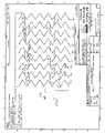
- FIG. 2is a plan view of a first embodiment of the inventive endoluminal stent.
- FIG. 3is a plan view of a second embodiment of the inventive endoluminal stent.
- FIG. 4is a plan view of a third embodiment of the inventive endoluminal stent.
- FIG. 5is a plan view of a fourth embodiment of the inventive endoluminal stent.
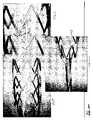
- FIG. 6is a photomicrograph of an interconnecting member and portions of circumferential expansion members of the inventive endoluminal stent.
- FIG. 7is a photomicrograph depicting the inventive endoluminal stent in its constricted diameter for endoluminal delivery within a constraining sheath.
- FIG. 8is a photomicrograph depicting the inventive endoluminal stent partially released from a constraining sheath and radially expanding.
- FIG. 9is photomicrograph depicting the inventive endoluminal stent in its radially enlarged diameter.
- the general configuration of the inventive endoluminal stentis substantially the same.
- the inventive endoluminal stent 10consists generally of a tubular cylindrical element comprised of a plurality of circumferential expansion elements 12 generally forming closed rings about the circumferential axis C′ of the stent 10 and arrayed in spaced apart relationship relative to one another coaxially along the longitudinal axis L′ of stent 10 .
- a plurality of interconnecting members 14interconnects adjacent pairs of the plurality of circumferential expansion elements 12 .
- Each of the plurality of circumferential expansion elements 12have a generally sinusoidal configuration with a plurality of peaks 12 p and a plurality of troughs 12 t of each circumferential expansion member and a plurality of struts 16 interconnecting adjacent peaks 12 p and troughs 12 t .
- the plurality of peaks 12 p and the plurality of troughs 12 t in one circumferential ring member 12may either be in phase or out of phase with the plurality of peaks 12 p and troughs 12 t in adjacent circumferential ring members 12 .
- each of the peaks 12 p and troughs 12 tmay have either regular or irregular periodicity or each of the plurality of circumferential expansion elements may have regions of regular periodicity and regions of irregular periodicity.
- Each of the plurality of interconnecting members 14preferably comprise generally linear elements having a width W i that interconnect a strut 16 of a first circumferential expansion element 12 with a strut 16 of a second, adjacent circumferential element 12 .
- Each of the plurality of interconnecting membershas a generally rectangular transverse cross-sectional shape.
- each of the plurality of interconnecting members 14 and the struts 16occurs at an approximate mid-point along the length of the strut 16 .
- Each of the plurality of struts 16has a width W s and is generally rectangular in transverse cross-section.
- a plurality of terminal flange members 11may be provided in order to provide affixation points for mounting a graft covering (not shown) onto the stent 10 .
- the terminal flange members 11may be positioned at the distal end, the proximal end or both ends of the stent 10 and preferably are formed generally linear projections from either peak 12 p or a trough 12 t of a terminal circumferential expansion element 12 at either or both of the proximal or distal ends of the stent 10 .
- Each of the plurality of flange members 11may further include a rounded distal or proximal end region to facilitate affixation of a graft covering.
- each generally U-shaped hinge element 22that connects adjacent struts along each circumferential expansion member 12 .
- W hwidth of the struts 16 to which it is connected.
- strain-relief sections 18 and 20at opposing ends of each of the plurality of interconnecting members 14 .
- the strain-relief sections 18 and 20comprise terminal sections of the interconnecting member 14 and have a width W t that is less than the width W i of the interconnecting member 14 .
- the strain-relief sections 18 and 20each have a generally C-shaped configuration and traverse a radius in connecting the interconnection member 14 with the struts 16 of adjacent circumferential expansion members 12 .
- C-shaped terminal strain-relief sections 18 and 20are also contemplated by the present invention, such as S-shaped, V-shaped, M-shaped, W-shaped, U-shaped, or merely generally I-shaped extensions projecting co-axially along the longitudinal axis of each interconnecting member 14 .
- FIGS. 2–5depict alternative preferred embodiments of the stent 10 of the present invention.
- Each of the preferred embodiments depicted in FIGS. 2–5include the same circumferential expansion elements 12 , each having a plurality of peaks 12 p and troughs 12 t and formed of a plurality of struts 16 interconnected at the peaks 12 p and troughs 12 t , and the generally U-shaped elements 22 forming the peaks 12 p and troughs 12 t , with adjacent pairs of circumferential expansion elements 12 being interconnected by the plurality of interconnecting members 14 .
- like elementsare identified by like reference numerals.
- each of the stents 30 , 40 , 50 and 60are illustrated in planar views.
- planar viewis depicted for ease of illustration and that the stents depicted are tubular with lines A—A and B—B forming division lines along the longitudinal axis L′ of the stents in order to illustrate the stent geometry in a planar view.
- stent 30is comprised of a plurality of circumferential expansion members 12 and a plurality of interconnecting members 14 .
- Each of the plurality of interconnecting members 14joins adjacent pairs of circumferential expansion members 12 .
- Each interconnecting member 14forms a junction with a strut 16 of each of the adjacent circumferential expansion members 12 and intersects the strut 16 at approximately a mid-point along the length of each strut 16 .
- the plurality of interconnecting members 14form groupings 14 a , 14 b , 14 c , 14 d , 14 e and 14 f along the longitudinal axis L′ of the stent 30 .
- each of the interconnecting members 14lie in the folding planes of the peaks 12 p and troughs 12 t and struts 16 about angle ⁇ , it has been found desirable to offset each of the interconnecting members 14 from a line parallel to the longitudinal axis L′ of the stent 30 by an angle ⁇ in order to enhance the folding properties of the circumferential expansion members 12 from a larger diameter to a smaller diameter of the stent 30 .
- each of the plurality of interconnecting members 14 in groupings 14 a – 14 fhave the same offset angle ⁇ and all of the plurality of interconnecting members 14 are parallel to each other.
- first strain relief section 18has a generally C-shaped configuration that has a right-handed or clockwise orientation
- second strain relief section 20also having a generally C-shaped configuration has a generally left-handed or counterclockwise orientation.
- interconnecting elements in groups 14 a , 14 c and 14 einterconnect circumferential expansion element pairs 12 a – 12 b , 12 c – 12 d , 12 e – 12 f , 12 g – 12 h and 12 i – 12 j
- interconnecting elements in groups 14 b , 14 d and 14 finterconnect circumferential expansion element pairs 12 b – 12 c , 12 d – 12 e , 12 f – 12 g , 12 h – 12 i .
- the interconnecting elements in group 14 a , 14 c and 14 eeach being offset by one peak l 2 p and one trough 12 t along the circumferential axis of each circumferential expansion element 12 .
- stent 40is illustrated and has a substantially identical configuration of circumferential expansion elements 12 and interconnecting elements 14 , except that instead of employing a 2:1 ratio of peaks 12 p or troughs 12 t to interconnecting elements, stent 40 employs a 3:1 ratio, such that each circumferential expansion element 12 a – 12 i has six peaks 12 p and six troughs 12 t , but adjacent pairs of circumferential elements 12 are interconnected by only two interconnecting elements 14 .
- the interconnecting elements of a first circumferential expansion element pairare circumferentially offset from the interconnecting elements of a second adjacent circumferential expansion element pair, except in stent 40 , the offset is either one peak 12 p and two troughs 12 t or two peaks 12 p and one trough 12 t .
- the offsetis either one peak 12 p and two troughs 12 t or two peaks 12 p and one trough 12 t .
- Interconnecting element groups 14 a and 14 cinterconnects circumferential expansion element pairs 12 b – 12 c , 12 d – 12 e , 12 f – 12 g and 12 h – 12 i , and interconnecting element groups 14 b and 14 d interconnect circumferential expansion element pairs 12 a – 12 b , 12 c – 12 d , 12 e – 12 f and 12 g – 12 h .
- each of the interconnecting elements 14are also angularly offset from the longitudinal axis of the stent by an angle ⁇ , except that the plurality of interconnecting elements 14 are not all parallel relative to each other. Rather, the interconnecting elements in interconnecting element groups 14 a and 14 c are parallel to each other and the interconnecting elements in interconnecting elements groups 14 b and 14 d are parallel to each other, with the interconnecting elements in groups 14 a and 14 c being offset from the longitudinal axis of the stent by an angle ⁇ which is alternate to the angle ⁇ , also denoted angle ⁇ +, forming the offset from the longitudinal axis L′ for the interconnecting elements in groups 14 b and 14 d .
- the designation angle ⁇ + and angle ⁇is intended to denote that these angles represent the substantially the same angular offset from the longitudinal axis L′, but have alternate orientations relative to the circumferential axis of the stent 40 .
- stent 50shares the common elements of circumferential expansion elements 12 , having a plurality of peaks 12 p and troughs 12 t interconnecting a plurality of struts 16 , and U-shaped sections 22 , and interconnecting elements 14 .
- the plurality of interconnecting elements 14form two groups of interconnecting elements 14 a and interconnecting elements 14 b .
- Each of the individual interconnecting elements 14 in interconnecting element groups 14 a and 14 bare also angularly offset from the longitudinal axis L′ of the stent 50 by angle ⁇ .
- each of the plurality of individual interconnecting elements 14are generally aligned along a common longitudinal axis. In this manner, with the exception of the most proximal 12 a and the most distal 12 i circumferential ring elements, each of the plurality of interconnecting elements form a substantially four-point junction 19 at approximately a mid-point a strut 16 on each of circumferential expansion elements 12 b – 12 h .
- the substantially four-point junction 19is formed between a distal strain relief section 20 of one interconnecting member with a proximal side of a strut 16 and a proximal strain relief section 18 of an adjacent interconnecting element 14 with a distal side of the same strut 16 .
- stent 60which, like stents 30 , 40 and 50 is comprised of a plurality of circumferential expansion elements 12 and interconnecting elements 14 that interconnect adjacent pairs of circumferential expansion elements 12 .
- stent 60has groupings of interconnecting elements 14 into interconnecting element groups 14 a , 14 b , 14 c and 14 d .
- interconnecting element groups 14 a and 14 dinterconnect identical pairs of circumferential expansion elements 12 and interconnecting element groups 14 b and 14 c interconnect identical pairs of circumferential expansion elements 12 .
- each of the interconnecting elements in interconnecting element groups 14 b and 14 dare angularly offset from the longitudinal axis L′ of the stent 60 by an angle ⁇ and are parallel to one and other.
- each of the interconnecting elements in interconnecting element groups 14 a and 14 care angularly offset from the longitudinal axis L′ of the stent 60 by an angle ⁇ + and are parallel to one and other.
- the interconnecting elements 14For each adjacent pair of circumferential expansion elements 12 , the interconnecting elements 14 have different orientations of angular offset from the longitudinal axis L′ of the stent 50 .
- the interconnecting elements of group 14 b and group 14 care offset by angle ⁇ and by angle ⁇ +, respectively.
- the interconnecting elements of group 14 a and 14 dare offset by angle ⁇ + and by angle ⁇ , respectively.
- the interconnecting elementsare out of phase, in that they have different angular orientations of angle ⁇ .
- the interconnecting elementsare circumferentially offset by a single peak 12 p , with interconnecting element group 14 a being circumferentially offset from interconnecting element group by a single peak 12 p , and interconnecting element group 14 c being circumferentially offset from interconnecting element group 14 d by a single peak 12 p . Furthermore, there are different circumferential offsets between interconnecting element group pairs 14 b – 14 c and 14 a – 14 d within individual pairs of adjacent circumferential expansion elements 12 .
- the circumferential offset between interconnecting element group pair 14 b – 14 cis two peaks 12 p and three troughs 12 t
- the circumferential offset between interconnecting element group pair 14 a – 14 dis four peaks 12 p and three troughs 12 t.
- stents 10 , 20 , 30 , 40 and 50describe various geometries all comprised of common structural elements, namely, circumferential expansion elements 12 having a plurality of peaks 12 p and troughs 12 t and struts 16 interconnected by hinge elements 22 .
- circumferential expansion elements 12having a plurality of peaks 12 p and troughs 12 t and struts 16 interconnected by hinge elements 22 .
- variations on the number of and positioning of the interconnecting members 14 between adjacent pairs of circumferential expansion elements 12 and along the circumferential axis of the stentare also contemplated by the present invention and that the specific embodiments illustrated and described with reference to the figures is exemplary in nature.
- FIG. 3represents a particularly preferred embodiment of the inventive stent 40 .
- inventive stent 40was fabricated by laser-cutting the described geometry from a nickel-titanium hypotube. After laser cutting, the stent 40 was annealed to set shape memory properties for the stent 40 with a fully expanded, enlarged outer diameter of 5.8 mm and a length of 30.6 mm. Stent 40 was capable of being crimped to a smaller, crimped outer diameter of 1.4 mm and was placed within a constraining sheath as illustrated in FIG. 7 . Stent 40 exhibited excellent crimpability with the struts 16 folding at the generally U-shaped hinge elements 22 through angle ⁇ without appreciable interference between the circumferential expansion elements 12 and the interconnecting elements 14 .
- the stent 40During radial expansion of the stent 40 from its first constrained smaller diameter, i.e., 1.4 mm, to its second enlarged radially expanded diameter, i.e., 5.8 mm, the stent 40 exhibited no foreshortening characteristic of many stent geometries known in the art. In contrast to foreshortening the stent 40 unexpectedly elongated by 2.5%. Heretofore a stent that elongates upon radial expansion is unknown in the art.
- FIG. 8depicts stent 40 radially expanding as it the constraining sheath is being withdrawn from the stent 40 .
- FIG. 9depicts stent 40 in virtually its fully radially expanded enlarged diameter, with just a proximal section of the stent 40 be constrained in the constraining sheath (not pictured).
- FIG. 6is an enlarged section of the stent 40 illustrating the mid-strut connection between the circumferential expansion element 12 and the interconnecting element 14 at the proximal and distal strain relief sections 18 and 20 , and clearly showing the generally U-shaped hinge elements 22 , the peaks 12 p and troughs 12 t of each circumferential expansion element 12 .
- the plurality of circumferential expansion elements 12 and interconnecting members 14 , and components sections thereof,are preferably made of materials selected from the group consisting of titanium, vanadium, aluminum, nickel, tantalum, zirconium, chromium, silver, gold, silicon, magnesium, niobium, scandium, platinum, cobalt, palladium, manganese, molybdenum and alloys thereof, and nitinol and stainless steel.
- the plurality of circumferential expansion elements 12 and the plurality of interconnecting members 14may be made of the same material or of different materials and have the same material properties or have different material properties.
- material propertiesis intended to encompass physical properties, including without limitation, elasticity, tensile strength, mechanical properties, hardness, bulk and/or surface grain size, grain composition, and grain boundary size, intra and inter-granular precipitates.
- materials selected for the plurality of circumferential expansion elements 12 and the plurality of interconnecting members 14may be selected to have the same or different chemical properties.
- chemical propertiesis intended to encompass both any chemical reaction and change of state that the material may undergo after being implanted into a body and the physiological response of the body to the material after implantation.
- inventive stentsmay be fabricated by chemical, thermal or mechanical ablative methods known in the art, such as chemical etching, laser cutting, EDM or water jet processes, it is envisioned that a preferred method for fabricating the inventive stents is by physical vapor deposition techniques. Physical vapor deposition techniques afford the ability to tightly control both the tolerances of the stent geometries as well as the physical and chemical properties of the stent and the stent materials.
- the inventive stents 10 , 30 , 40 , 50 and 60including each of their elements, namely the plurality of circumferential expansion elements 12 and interconnecting members 14 and component sections thereof, are preferably made of a bulk material having controlled heterogeneities on the luminal surface thereof.
- heterogeneitiesare controlled by fabricating the bulk material of the stent to have defined grain sizes, chemical and intra- and intergranular precipitates and where the bulk and surface morphology differ, yielding areas or sites along the surface of the stent while maintaining acceptable or optimal protein binding capability.
- the characteristically desirable properties of the inventive stentare: (a) optimum mechanical properties consistent with or exceeding regulatory approval criteria, (b) minimization of defects, such as cracking or pin hole defects, (c) a fatigue life of 400 MM cycles as measured by simulated accelerated testing, (d) corrosion and/or corrosion-fatigue resistance, (e) biocompatibility without having biologically significant impurities in the material, (f) a substantially non-frictional abluminal surface to facilitate atraumatic vascular crossing and tracking and compatible with transcatheter techniques for stent introduction, (g) radiopaque at selected sites and MRI compatible, (h) have a luminal surface which is optimized for surface energy and microtopography, (i) minimal manufacturing and material cost consistent with achieving the desired material properties, and (j) high process yields.
- the foregoing propertiesare achieved by fabricating a stent by the same metal deposition methodologies as are used and standard in the microelectronics and nano-fabrication vacuum coating arts, and which are hereby incorporated by reference.
- the preferred deposition methodologiesinclude ion-beam assisted evaporative deposition and sputtering techniques.
- ion beam-assisted evaporative depositionit is preferable to employ dual and simultaneous thermal electron beam evaporation with simultaneous ion bombardment of the substrate using an inert gas, such as argon, xenon, nitrogen or neon. Bombardment with an inert gas, such as argon ions serves to reduce void content by increasing the atomic packing density in the deposited material during deposition. The reduced void content in the deposited material allows the mechanical properties of that deposited material to be similar to the bulk material properties. Deposition rates up to 20 nm/sec are achievable using ion beam-assisted evaporative deposition techniques.
- a 200-micron thick stainless steel filmmay be deposited within about four hours of deposition time.
- a cylindrical sputtering targeta single circumferential source that concentrically surrounds the substrate that is held in a coaxial position within the source.
- Alternate deposition processes which may be employed to form the stent in accordance with the present inventionare cathodic arc, laser ablation, and direct ion beam deposition.
- the crystalline structure of the deposited filmaffects the mechanical properties of the deposited film. These mechanical properties of the deposited film may be modified by post-process treatment, such as by, for example, annealing, high-pressure treatment or gas quenching.
- Materials to make the inventive stentsare chosen for their biocompatibility, mechanical properties, i.e., tensile strength, yield strength, and their ease of deposition include the following: elemental titanium, vanadium, aluminum, nickel, tantalum, zirconium, chromium, silver, gold, silicon, magnesium, niobium, scandium, platinum, cobalt, palladium, manganese, molybdenum and alloys thereof, such as zirconium-titanium-tantalum alloys, nitinol, and stainless steel.
- the chamber pressure, the deposition pressure and the partial pressure of the process gasesare controlled to optimize deposition of the desired species onto the substrate.
- both the reactive and non-reactive gasesare controlled and the inert or non-reactive gaseous species introduced into the deposition chamber are typically argon and nitrogen.
- the substratemay be either stationary or moveable, either rotated about its longitudinal axis, or moved in an X-Y plane within the reactor to facilitate deposition or patterning of the deposited material onto the substrate.
- the deposited materialmay be deposited either as a uniform solid film onto the substrate, or patterned by (a) imparting either a positive or negative pattern onto the substrate, such as by etching or photolithography techniques applied to the substrate surface to create a positive or negative image of the desired pattern or (b) using a mask or set of masks which are either stationary or moveable relative to the substrate to define the pattern applied to the substrate.
- Patterningmay be employed to achieve complex finished geometries of the resultant stent, both in the context of spatial orientation of the pattern as well as the material thickness at different regions of the deposited film, such as by varying the wall thickness of the material over its length to thicken sections at proximal and distal ends of the stent to prevent flaring of the stent ends upon radial expansion of the stent.
- the stentmay be removed from the substrate after stent formation by any of a variety of methods.
- the substratemay be removed by chemical means, such as etching or dissolution, by ablation, by machining or by ultrasonic energy.
- a sacrificial layer of a materialsuch as carbon or aluminum, may be deposited intermediate the substrate and the stent and the sacrificial layer removed by melting, chemical means, ablation, machining or other suitable means to free the stent from the substrate.
- the resulting stentmay then be subjected to post-deposition processing to modify the crystalline structure, such as by annealing, or to modify the surface topography, such as by etching to affect and control the heterogeneities on the blood flow surface of the stent.
- a plurality of microgroovesmay be imparted onto the luminal and/or abluminal surface of the stent 10 , as is more fully described in International Publication No. WO 99/23977, published 20 May 1999, which is commonly assigned with the present application and is hereby incorporated by reference.
- the plurality of microgroovesmay be formed either as a post-deposition process step, such as by etching, or during deposition, such as by depositing the stent-forming material onto a mandrel which has a microtopography on the surface thereof which causes the metal to deposit with the microgroove pattern as part of the deposited material.
- Each of the preferred embodiments of the present inventionare preferably fabricated by employing a vapor deposition technique which entails vapor depositing a stent-forming metal onto a substrate.
- the substratemay be planar or cylindrical and is either pre-patterned with one of the preferred geometries of first and interconnecting members, in either positive or negative image, or the substrate may be un-patterned. Where the substrate is un-patterned, the deposited stent-forming metal is subjected to post-deposition patterning to pattern the deposited stent-forming metal into one of the preferred geometries of the first and interconnecting members.
- the need for post-deposition processing of the patterned endoluminal stente.g., modifying the surface of the stent by mechanical, electrical, thermal or chemical machining or polishing, is eliminated or minimized.
- Vapor deposition fabrication of the inventive endoluminal stentsoffers many advantages, including, for example, the ability to fabricate stents of complex geometries, ultrafine dimensional tolerances on the order of Angstroms, the ability to control fatigue life, corrosion resistance, corrosion fatigue, inter- and intra-granular precipitates and their effect on corrosion resistance and corrosion fatigue, bulk material composition, bulk and surface material properties, radioopacity, and the ability to vary the transverse profiles, Z-axis thickness and X-Y-axis surface area of the stent structural elements in manners that affect the longitudinal flexibility, hoop strength, and radial expansion behavior and profile of the stent.
- Bulk material compositionmay be adjusted to employ elemental fractions in alloy compositions that are not feasible when using conventionally formed metals.
- nickel-titanium tubes exhibiting shape memory and/or superelastic propertieswere made employing in excess of 51.5 atomic percent nickel, which is not achievable using conventional working techniques due to high plateau stresses exhibited by the material.
- the present inventorshave fabricated nickel-titanium alloy tubes employing the method of the present invention that contain between 51.5 and 55 atomic percent nickel.
- Vapor deposition of the inventive endoluminal stentsignificantly reduces or virtually eliminates inter- and intra-granular precipitates in the bulk material. It is common practice in the nickel-titanium endoluminal device industry to control transition temperatures and resulting mechanical properties by altering local granular nickel-titanium ratios by precipitation regimens. In the present invention, the need to control precipitates for mechanical properties is eliminated. Where nickel-titanium is employed as the stent-forming metal in the present invention, local nickel-titanium ratios will be the same or virtually identical to the nickel-titanium ratios in the bulk material, while still allowing for optimal morphology and eliminating the need for employing precipitation heat treatment. The resulting deposited stent-forming metal exhibits superior corrosion resistance, and hence, resistance to corrosion fatigue, when compared to conventional wrought nickel-titanium alloys.
- the plurality of circumferential expansion elements 12 and the plurality of interconnecting members 14may be conformationally configured during vapor deposition to impart a generally rectangular, ovular or elliptical transverse cross-sectional profile with either right angled edges or with chamfered or curved leading and trailing luminal and abluminal surface edges in the longitudinal axis of the stent in order to provide better blood flow surface profiles.
Landscapes
- Health & Medical Sciences (AREA)
- Engineering & Computer Science (AREA)
- Biomedical Technology (AREA)
- Heart & Thoracic Surgery (AREA)
- Life Sciences & Earth Sciences (AREA)
- Cardiology (AREA)
- Oral & Maxillofacial Surgery (AREA)
- Transplantation (AREA)
- Physics & Mathematics (AREA)
- Vascular Medicine (AREA)
- Optics & Photonics (AREA)
- Animal Behavior & Ethology (AREA)
- General Health & Medical Sciences (AREA)
- Public Health (AREA)
- Veterinary Medicine (AREA)
- Prostheses (AREA)
- Media Introduction/Drainage Providing Device (AREA)
- Materials For Medical Uses (AREA)
Abstract
Description
Claims (10)
Priority Applications (2)
| Application Number | Priority Date | Filing Date | Title |
|---|---|---|---|
| US10/803,392US7122049B2 (en) | 2003-03-19 | 2004-03-18 | Endoluminal stent having mid-strut interconnecting members |
| US11/549,493US7980289B2 (en) | 2003-03-19 | 2006-10-13 | Endoluminal stent having mid-strut interconnecting members |
Applications Claiming Priority (2)
| Application Number | Priority Date | Filing Date | Title |
|---|---|---|---|
| US45578303P | 2003-03-19 | 2003-03-19 | |
| US10/803,392US7122049B2 (en) | 2003-03-19 | 2004-03-18 | Endoluminal stent having mid-strut interconnecting members |
Related Child Applications (1)
| Application Number | Title | Priority Date | Filing Date |
|---|---|---|---|
| US11/549,493ContinuationUS7980289B2 (en) | 2003-03-19 | 2006-10-13 | Endoluminal stent having mid-strut interconnecting members |
Publications (2)
| Publication Number | Publication Date |
|---|---|
| US20040186554A1 US20040186554A1 (en) | 2004-09-23 |
| US7122049B2true US7122049B2 (en) | 2006-10-17 |
Family
ID=34572701
Family Applications (2)
| Application Number | Title | Priority Date | Filing Date |
|---|---|---|---|
| US10/803,392Expired - LifetimeUS7122049B2 (en) | 2003-03-19 | 2004-03-18 | Endoluminal stent having mid-strut interconnecting members |
| US11/549,493Active2027-05-31US7980289B2 (en) | 2003-03-19 | 2006-10-13 | Endoluminal stent having mid-strut interconnecting members |
Family Applications After (1)
| Application Number | Title | Priority Date | Filing Date |
|---|---|---|---|
| US11/549,493Active2027-05-31US7980289B2 (en) | 2003-03-19 | 2006-10-13 | Endoluminal stent having mid-strut interconnecting members |
Country Status (10)
| Country | Link |
|---|---|
| US (2) | US7122049B2 (en) |
| EP (2) | EP1610724B1 (en) |
| JP (1) | JP5021298B2 (en) |
| CN (1) | CN100558320C (en) |
| AT (1) | ATE492246T1 (en) |
| AU (1) | AU2004224415B2 (en) |
| CA (1) | CA2519226C (en) |
| DE (1) | DE602004030671D1 (en) |
| MX (1) | MXPA05009823A (en) |
| WO (1) | WO2004084764A2 (en) |
Cited By (20)
| Publication number | Priority date | Publication date | Assignee | Title |
|---|---|---|---|---|
| US20060235505A1 (en)* | 2005-03-14 | 2006-10-19 | Oepen Randolf V | Visible endoprosthesis |
| US20070213810A1 (en)* | 2005-03-14 | 2007-09-13 | Richard Newhauser | Segmented endoprosthesis |
| US20070255094A1 (en)* | 2005-03-14 | 2007-11-01 | Oepen Randolf V | Crack/fatigue resistant endoprosthesis |
| US20080154354A1 (en)* | 1998-07-08 | 2008-06-26 | Boston Scientific Scimed, Inc. | Stent |
| US20100010622A1 (en)* | 2006-03-13 | 2010-01-14 | Abbott Laboratories | Hybrid segmented endoprosthesis |
| US20110060399A1 (en)* | 2008-04-08 | 2011-03-10 | Steven J Charlebois | Surface structure of a component of a medical device and a method of forming the surface structure |
| WO2012040645A1 (en) | 2010-09-24 | 2012-03-29 | Veniti, Inc. | Stent with support braces |
| US8864811B2 (en) | 2010-06-08 | 2014-10-21 | Veniti, Inc. | Bi-directional stent delivery system |
| USD723165S1 (en) | 2013-03-12 | 2015-02-24 | C. R. Bard, Inc. | Stent |
| US8974514B2 (en) | 2007-03-13 | 2015-03-10 | Abbott Cardiovascular Systems Inc. | Intravascular stent with integrated link and ring strut |
| US8999364B2 (en) | 2004-06-15 | 2015-04-07 | Nanyang Technological University | Implantable article, method of forming same and method for reducing thrombogenicity |
| US9066825B2 (en) | 2012-05-14 | 2015-06-30 | C.R. Bard, Inc. | Uniformly expandable stent |
| US9301864B2 (en) | 2010-06-08 | 2016-04-05 | Veniti, Inc. | Bi-directional stent delivery system |
| US9649211B2 (en) | 2009-11-04 | 2017-05-16 | Confluent Medical Technologies, Inc. | Alternating circumferential bridge stent design and methods for use thereof |
| US9907640B2 (en) | 2013-06-21 | 2018-03-06 | Boston Scientific Scimed, Inc. | Stent with deflecting connector |
| US9908143B2 (en) | 2008-06-20 | 2018-03-06 | Amaranth Medical Pte. | Stent fabrication via tubular casting processes |
| US10092427B2 (en) | 2009-11-04 | 2018-10-09 | Confluent Medical Technologies, Inc. | Alternating circumferential bridge stent design and methods for use thereof |
| US10155247B2 (en)* | 2011-08-01 | 2018-12-18 | Abbott Cardiovascular Systems Inc. | Multiple scaffold design and coating thereof |
| US10646359B2 (en) | 2008-06-20 | 2020-05-12 | Amaranth Medical Pte. | Stent fabrication via tubular casting processes |
| US11931484B2 (en) | 2008-06-20 | 2024-03-19 | Razmodics Llc | Composite stent having multi-axial flexibility and method of manufacture thereof |
Families Citing this family (23)
| Publication number | Priority date | Publication date | Assignee | Title |
|---|---|---|---|---|
| US7736687B2 (en) | 2006-01-31 | 2010-06-15 | Advance Bio Prosthetic Surfaces, Ltd. | Methods of making medical devices |
| US6923829B2 (en) | 2002-11-25 | 2005-08-02 | Advanced Bio Prosthetic Surfaces, Ltd. | Implantable expandable medical devices having regions of differential mechanical properties and methods of making same |
| US20080220039A1 (en)* | 2004-09-17 | 2008-09-11 | Sherman Darren R | Thin Film Medical Devices Manufactured on Application Specific Core Shapes |
| US7344560B2 (en)* | 2004-10-08 | 2008-03-18 | Boston Scientific Scimed, Inc. | Medical devices and methods of making the same |
| US20070088428A1 (en)* | 2005-09-15 | 2007-04-19 | Cappella, Inc. | Intraluminal device with asymmetric cap portion |
| US20070061003A1 (en)* | 2005-09-15 | 2007-03-15 | Cappella, Inc. | Segmented ostial protection device |
| JP2010504174A (en)* | 2006-09-21 | 2010-02-12 | クレベニー テクノロジーズ | Specially constructed and surface-modified medical devices with certain design features that take advantage of the unique properties of tungsten, zirconium, tantalum, and / or niobium |
| EP2166984B1 (en)* | 2007-06-22 | 2016-08-31 | C.R. Bard, Inc. | Flexible stent with hinged connectors |
| US20090210049A1 (en)* | 2008-02-15 | 2009-08-20 | Joseph Michael Thielen | Peripheral overlap stent |
| PL4223257T3 (en)* | 2008-06-06 | 2024-09-23 | Edwards Lifesciences Corporation | LOW-PROFILE TRANSCATHETIC HEART VALVE |
| US8986374B2 (en)* | 2010-05-10 | 2015-03-24 | Edwards Lifesciences Corporation | Prosthetic heart valve |
| CN102743245A (en)* | 2011-04-22 | 2012-10-24 | 陈启星 | Support opening type tubular vascular stent |
| US8728563B2 (en)* | 2011-05-03 | 2014-05-20 | Palmaz Scientific, Inc. | Endoluminal implantable surfaces, stents, and grafts and method of making same |
| US8834556B2 (en)* | 2012-08-13 | 2014-09-16 | Abbott Cardiovascular Systems Inc. | Segmented scaffold designs |
| US9956097B2 (en)* | 2012-10-23 | 2018-05-01 | Abbott Cardiovascular Systems Inc. | Methods for vascular restoration therapy |
| CN107184292B (en)* | 2013-03-13 | 2020-07-10 | 爱德华兹生命科学卡迪尔克有限责任公司 | Articulating commissure valve stents and methods |
| US10271975B2 (en) | 2013-03-15 | 2019-04-30 | Atrium Medical Corporation | Stent device having reduced foreshortening and recoil and method of making same |
| WO2016110875A1 (en)* | 2015-01-07 | 2016-07-14 | Sahajanand Medical Technologies Private Limited | Endoluminal stent |
| EP3367967B1 (en) | 2015-10-27 | 2020-02-12 | Contego Medical, LLC | Transluminal angioplasty devices |
| JP2019076121A (en)* | 2016-03-18 | 2019-05-23 | テルモ株式会社 | Stent |
| US10603165B2 (en) | 2016-12-06 | 2020-03-31 | Edwards Lifesciences Corporation | Mechanically expanding heart valve and delivery apparatus therefor |
| CN109091275B (en)* | 2018-08-24 | 2024-01-30 | 四川大学 | Biodegradable stent |
| EP4629933A1 (en)* | 2022-12-09 | 2025-10-15 | Renata Medical, Inc. | Transcatheter growth devices and methods for norwood, glenn and fontan therapy |
Citations (66)
| Publication number | Priority date | Publication date | Assignee | Title |
|---|---|---|---|---|
| US4733665A (en) | 1985-11-07 | 1988-03-29 | Expandable Grafts Partnership | Expandable intraluminal graft, and method and apparatus for implanting an expandable intraluminal graft |
| US5421955A (en) | 1991-10-28 | 1995-06-06 | Advanced Cardiovascular Systems, Inc. | Expandable stents and method for making same |
| US5569295A (en) | 1993-12-28 | 1996-10-29 | Advanced Cardiovascular Systems, Inc. | Expandable stents and method for making same |
| US5733303A (en) | 1994-03-17 | 1998-03-31 | Medinol Ltd. | Flexible expandable stent |
| US5759192A (en) | 1994-11-28 | 1998-06-02 | Advanced Cardiovascular Systems, Inc. | Method and apparatus for direct laser cutting of metal stents |
| US5772864A (en) | 1996-02-23 | 1998-06-30 | Meadox Medicals, Inc. | Method for manufacturing implantable medical devices |
| US5776161A (en)* | 1995-10-16 | 1998-07-07 | Instent, Inc. | Medical stents, apparatus and method for making same |
| US5807404A (en) | 1996-09-19 | 1998-09-15 | Medinol Ltd. | Stent with variable features to optimize support and method of making such stent |
| US5817126A (en) | 1997-03-17 | 1998-10-06 | Surface Genesis, Inc. | Compound stent |
| US5843120A (en) | 1994-03-17 | 1998-12-01 | Medinol Ltd. | Flexible-expandable stent |
| US5843164A (en) | 1994-11-15 | 1998-12-01 | Advanced Carrdiovascular Systems, Inc. | Intraluminal stent for attaching a graft |
| US5853419A (en) | 1997-03-17 | 1998-12-29 | Surface Genesis, Inc. | Stent |
| US5868782A (en) | 1996-12-24 | 1999-02-09 | Global Therapeutics, Inc. | Radially expandable axially non-contracting surgical stent |
| US5876432A (en) | 1994-04-01 | 1999-03-02 | Gore Enterprise Holdings, Inc. | Self-expandable helical intravascular stent and stent-graft |
| US5919225A (en) | 1994-09-08 | 1999-07-06 | Gore Enterprise Holdings, Inc. | Procedures for introducing stents and stent-grafts |
| US5938682A (en) | 1996-01-26 | 1999-08-17 | Cordis Corporation | Axially flexible stent |
| FR2777771A1 (en) | 1998-04-27 | 1999-10-29 | Microval | Flexible tubular vascular endoprosthesis used e.g. in angioplasty |
| US6033433A (en) | 1997-04-25 | 2000-03-07 | Scimed Life Systems, Inc. | Stent configurations including spirals |
| US6042597A (en) | 1998-10-23 | 2000-03-28 | Scimed Life Systems, Inc. | Helical stent design |
| US6059808A (en) | 1996-04-10 | 2000-05-09 | Laboratoires Nycomed Sa | Implantable device and delivery system to reestablish or maintain a bodily canal |
| US6059810A (en) | 1995-05-10 | 2000-05-09 | Scimed Life Systems, Inc. | Endovascular stent and method |
| US6063101A (en) | 1998-11-20 | 2000-05-16 | Precision Vascular Systems, Inc. | Stent apparatus and method |
| US6066169A (en)* | 1998-06-02 | 2000-05-23 | Ave Connaught | Expandable stent having articulated connecting rods |
| US6103320A (en) | 1998-03-05 | 2000-08-15 | Shincron Co., Ltd. | Method for forming a thin film of a metal compound by vacuum deposition |
| US6120847A (en) | 1999-01-08 | 2000-09-19 | Scimed Life Systems, Inc. | Surface treatment method for stent coating |
| US6124523A (en) | 1995-03-10 | 2000-09-26 | Impra, Inc. | Encapsulated stent |
| US6129755A (en) | 1998-01-09 | 2000-10-10 | Nitinol Development Corporation | Intravascular stent having an improved strut configuration |
| WO2001049212A1 (en) | 1999-12-30 | 2001-07-12 | Advanced Cardiovascular Systems, Inc. | Stent designs for use in peripheral vessels |
| US6270524B1 (en) | 1996-11-12 | 2001-08-07 | Medtronic, Inc. | Flexible, radially expansible luminal prostheses |
| US6293966B1 (en) | 1997-05-06 | 2001-09-25 | Cook Incorporated | Surgical stent featuring radiopaque markers |
| US6309414B1 (en) | 1997-11-04 | 2001-10-30 | Sorin Biomedica Cardio S.P.A. | Angioplasty stents |
| US6312463B1 (en) | 2000-02-01 | 2001-11-06 | Endotex Interventional Systems, Inc. | Micro-porous mesh stent with hybrid structure |
| US20010047200A1 (en) | 1999-10-13 | 2001-11-29 | Raymond Sun | Non-foreshortening intraluminal prosthesis |
| US20010047201A1 (en) | 1999-04-22 | 2001-11-29 | Cox Daniel L. | Variable strength stent |
| US6325826B1 (en) | 1998-01-14 | 2001-12-04 | Advanced Stent Technologies, Inc. | Extendible stent apparatus |
| US6325821B1 (en) | 1997-04-29 | 2001-12-04 | Sorin Biomedica Cardio S.P.A. | Stent for angioplasty |
| US6331190B1 (en) | 1998-03-04 | 2001-12-18 | Endologix, Inc. | Endoluminal vascular prosthesis |
| US20010056298A1 (en) | 1995-03-01 | 2001-12-27 | Brown Brian J. | Longitudinally flexible expandable stent |
| US6334871B1 (en) | 1996-03-13 | 2002-01-01 | Medtronic, Inc. | Radiopaque stent markers |
| US6336938B1 (en) | 1992-08-06 | 2002-01-08 | William Cook Europe A/S | Implantable self expanding prosthetic device |
| US20020007209A1 (en) | 2000-03-06 | 2002-01-17 | Scheerder Ivan De | Intraluminar perforated radially expandable drug delivery prosthesis and a method for the production thereof |
| US20020016623A1 (en) | 1999-04-08 | 2002-02-07 | Kula John S. | Stent with variable wall thickness |
| US6355058B1 (en) | 1999-12-30 | 2002-03-12 | Advanced Cardiovascular Systems, Inc. | Stent with radiopaque coating consisting of particles in a binder |
| US20020042649A1 (en) | 2000-10-10 | 2002-04-11 | Biotronik Mess-Und Therapiegeraete Gmbh & Co. Ingenieurbuero Berlin | Stent |
| US20020045935A1 (en) | 2000-09-23 | 2002-04-18 | Jang G. David | Intravascular stent apparatus |
| US20020055770A1 (en) | 1998-11-20 | 2002-05-09 | Doran Burns P. | Flexible and expandable stent |
| US6387123B1 (en) | 1999-10-13 | 2002-05-14 | Advanced Cardiovascular Systems, Inc. | Stent with radiopaque core |
| WO2002038080A2 (en) | 2000-11-07 | 2002-05-16 | Advanced Bio Prosthetic Surfaces, Ltd. | Endoluminal stent, self-fupporting endoluminal graft and methods of making same |
| EP1212986A1 (en) | 2000-12-08 | 2002-06-12 | SORIN BIOMEDICA CARDIO S.p.A. | An angioplasty stent and manufacturing method thereof |
| US20020123798A1 (en)* | 2001-03-01 | 2002-09-05 | Robert Burgermeister | Flexible stent |
| US6451049B2 (en) | 1998-04-29 | 2002-09-17 | Sorin Biomedica Cardio, S.P.A. | Stents for angioplasty |
| US6461380B1 (en)* | 1998-07-28 | 2002-10-08 | Advanced Cardiovascular Systems, Inc. | Stent configuration |
| US20020156523A1 (en) | 1994-08-31 | 2002-10-24 | Lilip Lau | Exterior supported self-expanding stent-graft |
| US6475236B1 (en) | 1997-02-07 | 2002-11-05 | Endosystems, Llc | Non-foreshortening intraluminal prosthesis |
| US6485508B1 (en) | 2000-10-13 | 2002-11-26 | Mcguinness Colm P. | Low profile stent |
| US6503272B2 (en) | 2001-03-21 | 2003-01-07 | Cordis Corporation | Stent-based venous valves |
| US6506211B1 (en) | 2000-11-13 | 2003-01-14 | Scimed Life Systems, Inc. | Stent designs |
| US6540774B1 (en)* | 1999-08-31 | 2003-04-01 | Advanced Cardiovascular Systems, Inc. | Stent design with end rings having enhanced strength and radiopacity |
| US20030083646A1 (en) | 2000-12-22 | 2003-05-01 | Avantec Vascular Corporation | Apparatus and methods for variably controlled substance delivery from implanted prostheses |
| US6605110B2 (en)* | 2001-06-29 | 2003-08-12 | Advanced Cardiovascular Systems, Inc. | Stent with enhanced bendability and flexibility |
| US6613079B1 (en)* | 1998-02-05 | 2003-09-02 | Medtronic, Inc. | Radially-expandable stent with controllable force profile |
| US6673106B2 (en) | 2001-06-14 | 2004-01-06 | Cordis Neurovascular, Inc. | Intravascular stent device |
| US6699278B2 (en) | 2000-09-22 | 2004-03-02 | Cordis Corporation | Stent with optimal strength and radiopacity characteristics |
| US20040054399A1 (en) | 2002-09-17 | 2004-03-18 | Roth Noah M. | Anti-galvanic stent coating |
| US6709454B1 (en) | 1999-05-17 | 2004-03-23 | Advanced Cardiovascular Systems, Inc. | Self-expanding stent with enhanced delivery precision and stent delivery system |
| US6730116B1 (en)* | 1999-04-16 | 2004-05-04 | Medtronic, Inc. | Medical device for intraluminal endovascular stenting |
Family Cites Families (6)
| Publication number | Priority date | Publication date | Assignee | Title |
|---|---|---|---|---|
| US6070589A (en)* | 1997-08-01 | 2000-06-06 | Teramed, Inc. | Methods for deploying bypass graft stents |
| US6203732B1 (en)* | 1998-07-02 | 2001-03-20 | Intra Therapeutics, Inc. | Method for manufacturing intraluminal device |
| DE19829702C1 (en)* | 1998-07-03 | 2000-03-16 | Heraeus Gmbh W C | Radially expandable support device V |
| US6261319B1 (en)* | 1998-07-08 | 2001-07-17 | Scimed Life Systems, Inc. | Stent |
| US6245101B1 (en)* | 1999-05-03 | 2001-06-12 | William J. Drasler | Intravascular hinge stent |
| US6565599B1 (en)* | 2000-12-28 | 2003-05-20 | Advanced Cardiovascular Systems, Inc. | Hybrid stent |
- 2004
- 2004-03-18CACA2519226Apatent/CA2519226C/ennot_activeExpired - Lifetime
- 2004-03-18JPJP2006507303Apatent/JP5021298B2/ennot_activeExpired - Lifetime
- 2004-03-18ATAT04757798Tpatent/ATE492246T1/ennot_activeIP Right Cessation
- 2004-03-18AUAU2004224415Apatent/AU2004224415B2/ennot_activeExpired
- 2004-03-18WOPCT/US2004/008247patent/WO2004084764A2/enactiveApplication Filing
- 2004-03-18MXMXPA05009823Apatent/MXPA05009823A/enactiveIP Right Grant
- 2004-03-18EPEP04757798Apatent/EP1610724B1/ennot_activeExpired - Lifetime
- 2004-03-18EPEP10185232.5Apatent/EP2289464B1/ennot_activeExpired - Lifetime
- 2004-03-18CNCNB2004800129661Apatent/CN100558320C/ennot_activeExpired - Lifetime
- 2004-03-18USUS10/803,392patent/US7122049B2/ennot_activeExpired - Lifetime
- 2004-03-18DEDE602004030671Tpatent/DE602004030671D1/ennot_activeExpired - Lifetime
- 2006
- 2006-10-13USUS11/549,493patent/US7980289B2/enactiveActive
Patent Citations (93)
| Publication number | Priority date | Publication date | Assignee | Title |
|---|---|---|---|---|
| US4739762B1 (en) | 1985-11-07 | 1998-10-27 | Expandable Grafts Partnership | Expandable intraluminal graft and method and apparatus for implanting an expandable intraluminal graft |
| US4739762A (en) | 1985-11-07 | 1988-04-26 | Expandable Grafts Partnership | Expandable intraluminal graft, and method and apparatus for implanting an expandable intraluminal graft |
| US4776337A (en) | 1985-11-07 | 1988-10-11 | Expandable Grafts Partnership | Expandable intraluminal graft, and method and apparatus for implanting an expandable intraluminal graft |
| US4733665B1 (en) | 1985-11-07 | 1994-01-11 | Expandable Grafts Partnership | Expandable intraluminal graft,and method and apparatus for implanting an expandable intraluminal graft |
| US4733665A (en) | 1985-11-07 | 1988-03-29 | Expandable Grafts Partnership | Expandable intraluminal graft, and method and apparatus for implanting an expandable intraluminal graft |
| US4776337B1 (en) | 1985-11-07 | 2000-12-05 | Cordis Corp | Expandable intraluminal graft and method and apparatus for implanting an expandable intraluminal graft |
| US4733665C2 (en) | 1985-11-07 | 2002-01-29 | Expandable Grafts Partnership | Expandable intraluminal graft and method and apparatus for implanting an expandable intraluminal graft |
| US6066168A (en) | 1991-10-28 | 2000-05-23 | Advanced Cardiovascular Systems, Inc. | Expandable stents and method for making same |
| US6066167A (en) | 1991-10-28 | 2000-05-23 | Advanced Cardiovascular Systems, Inc. | Expandable stents |
| US5728158A (en) | 1991-10-28 | 1998-03-17 | Advanced Cardiovascular Systems, Inc. | Expandable stents |
| US6689159B2 (en) | 1991-10-28 | 2004-02-10 | Advanced Cardiovascular Systems, Inc. | Expandable stents and method for making same |
| US5735893A (en) | 1991-10-28 | 1998-04-07 | Advanced Cardiovascular Systems, Inc. | Expandable stents and method for making same |
| US20010037146A1 (en) | 1991-10-28 | 2001-11-01 | Lilip Lau | Expandable stents and method for making same |
| US5766238A (en) | 1991-10-28 | 1998-06-16 | Advanced Cardiovascular Systems, Inc. | Expandable stents and method for making same |
| US20010037147A1 (en) | 1991-10-28 | 2001-11-01 | Lilip Lau | Expandable stents and method for making same |
| US6309412B1 (en) | 1991-10-28 | 2001-10-30 | Advanced Cardiovascular Systems, Inc. | Expandable stents and method for making same |
| US5421955A (en) | 1991-10-28 | 1995-06-06 | Advanced Cardiovascular Systems, Inc. | Expandable stents and method for making same |
| US5514154A (en) | 1991-10-28 | 1996-05-07 | Advanced Cardiovascular Systems, Inc. | Expandable stents |
| US6056776A (en) | 1991-10-28 | 2000-05-02 | Advanced Cardiovascular System, Inc. | Expandable stents and method for making same |
| US5603721A (en) | 1991-10-28 | 1997-02-18 | Advanced Cardiovascular Systems, Inc. | Expandable stents and method for making same |
| US5421955B1 (en) | 1991-10-28 | 1998-01-20 | Advanced Cardiovascular System | Expandable stents and method for making same |
| US6432133B1 (en) | 1991-10-28 | 2002-08-13 | Advanced Cardiovascular Systems, Inc. | Expandable stents and method for making same |
| US6336938B1 (en) | 1992-08-06 | 2002-01-08 | William Cook Europe A/S | Implantable self expanding prosthetic device |
| US5569295A (en) | 1993-12-28 | 1996-10-29 | Advanced Cardiovascular Systems, Inc. | Expandable stents and method for making same |
| US5843120A (en) | 1994-03-17 | 1998-12-01 | Medinol Ltd. | Flexible-expandable stent |
| US5733303A (en) | 1994-03-17 | 1998-03-31 | Medinol Ltd. | Flexible expandable stent |
| US5876432A (en) | 1994-04-01 | 1999-03-02 | Gore Enterprise Holdings, Inc. | Self-expandable helical intravascular stent and stent-graft |
| US20020156523A1 (en) | 1994-08-31 | 2002-10-24 | Lilip Lau | Exterior supported self-expanding stent-graft |
| US6015429A (en) | 1994-09-08 | 2000-01-18 | Gore Enterprise Holdings, Inc. | Procedures for introducing stents and stent-grafts |
| US5919225A (en) | 1994-09-08 | 1999-07-06 | Gore Enterprise Holdings, Inc. | Procedures for introducing stents and stent-grafts |
| US5843164A (en) | 1994-11-15 | 1998-12-01 | Advanced Carrdiovascular Systems, Inc. | Intraluminal stent for attaching a graft |
| US5780807A (en) | 1994-11-28 | 1998-07-14 | Advanced Cardiovascular Systems, Inc. | Method and apparatus for direct laser cutting of metal stents |
| US5759192A (en) | 1994-11-28 | 1998-06-02 | Advanced Cardiovascular Systems, Inc. | Method and apparatus for direct laser cutting of metal stents |
| US20010056298A1 (en) | 1995-03-01 | 2001-12-27 | Brown Brian J. | Longitudinally flexible expandable stent |
| US6124523A (en) | 1995-03-10 | 2000-09-26 | Impra, Inc. | Encapsulated stent |
| US6059810A (en) | 1995-05-10 | 2000-05-09 | Scimed Life Systems, Inc. | Endovascular stent and method |
| US5776161A (en)* | 1995-10-16 | 1998-07-07 | Instent, Inc. | Medical stents, apparatus and method for making same |
| US5938682A (en) | 1996-01-26 | 1999-08-17 | Cordis Corporation | Axially flexible stent |
| US5772864A (en) | 1996-02-23 | 1998-06-30 | Meadox Medicals, Inc. | Method for manufacturing implantable medical devices |
| US6334871B1 (en) | 1996-03-13 | 2002-01-01 | Medtronic, Inc. | Radiopaque stent markers |
| US6059808A (en) | 1996-04-10 | 2000-05-09 | Laboratoires Nycomed Sa | Implantable device and delivery system to reestablish or maintain a bodily canal |
| US5807404A (en) | 1996-09-19 | 1998-09-15 | Medinol Ltd. | Stent with variable features to optimize support and method of making such stent |
| US6270524B1 (en) | 1996-11-12 | 2001-08-07 | Medtronic, Inc. | Flexible, radially expansible luminal prostheses |
| US5868782A (en) | 1996-12-24 | 1999-02-09 | Global Therapeutics, Inc. | Radially expandable axially non-contracting surgical stent |
| US6475236B1 (en) | 1997-02-07 | 2002-11-05 | Endosystems, Llc | Non-foreshortening intraluminal prosthesis |
| US5817126A (en) | 1997-03-17 | 1998-10-06 | Surface Genesis, Inc. | Compound stent |
| US5853419A (en) | 1997-03-17 | 1998-12-29 | Surface Genesis, Inc. | Stent |
| US6033433A (en) | 1997-04-25 | 2000-03-07 | Scimed Life Systems, Inc. | Stent configurations including spirals |
| US6334870B1 (en) | 1997-04-25 | 2002-01-01 | Scimed Life Systems, Inc. | Stent configurations including spirals |
| US6325821B1 (en) | 1997-04-29 | 2001-12-04 | Sorin Biomedica Cardio S.P.A. | Stent for angioplasty |
| US20020183831A1 (en) | 1997-04-29 | 2002-12-05 | Sorin Biomedica Cardio S.P.A. | Stents for angioplasty |
| US6293966B1 (en) | 1997-05-06 | 2001-09-25 | Cook Incorporated | Surgical stent featuring radiopaque markers |
| US20020072793A1 (en) | 1997-11-04 | 2002-06-13 | Sorin Biomedica Cardio S.P.A. | Angioplasty stents |
| US6309414B1 (en) | 1997-11-04 | 2001-10-30 | Sorin Biomedica Cardio S.P.A. | Angioplasty stents |
| US6129755A (en) | 1998-01-09 | 2000-10-10 | Nitinol Development Corporation | Intravascular stent having an improved strut configuration |
| US6325826B1 (en) | 1998-01-14 | 2001-12-04 | Advanced Stent Technologies, Inc. | Extendible stent apparatus |
| US6613079B1 (en)* | 1998-02-05 | 2003-09-02 | Medtronic, Inc. | Radially-expandable stent with controllable force profile |
| US6331190B1 (en) | 1998-03-04 | 2001-12-18 | Endologix, Inc. | Endoluminal vascular prosthesis |
| US6103320A (en) | 1998-03-05 | 2000-08-15 | Shincron Co., Ltd. | Method for forming a thin film of a metal compound by vacuum deposition |
| FR2777771A1 (en) | 1998-04-27 | 1999-10-29 | Microval | Flexible tubular vascular endoprosthesis used e.g. in angioplasty |
| US6451049B2 (en) | 1998-04-29 | 2002-09-17 | Sorin Biomedica Cardio, S.P.A. | Stents for angioplasty |
| US6066169A (en)* | 1998-06-02 | 2000-05-23 | Ave Connaught | Expandable stent having articulated connecting rods |
| US6461380B1 (en)* | 1998-07-28 | 2002-10-08 | Advanced Cardiovascular Systems, Inc. | Stent configuration |
| US6042597A (en) | 1998-10-23 | 2000-03-28 | Scimed Life Systems, Inc. | Helical stent design |
| US6063101A (en) | 1998-11-20 | 2000-05-16 | Precision Vascular Systems, Inc. | Stent apparatus and method |
| US20020055770A1 (en) | 1998-11-20 | 2002-05-09 | Doran Burns P. | Flexible and expandable stent |
| US6120847A (en) | 1999-01-08 | 2000-09-19 | Scimed Life Systems, Inc. | Surface treatment method for stent coating |
| US20020016623A1 (en) | 1999-04-08 | 2002-02-07 | Kula John S. | Stent with variable wall thickness |
| US6730116B1 (en)* | 1999-04-16 | 2004-05-04 | Medtronic, Inc. | Medical device for intraluminal endovascular stenting |
| US20010047201A1 (en) | 1999-04-22 | 2001-11-29 | Cox Daniel L. | Variable strength stent |
| US6709454B1 (en) | 1999-05-17 | 2004-03-23 | Advanced Cardiovascular Systems, Inc. | Self-expanding stent with enhanced delivery precision and stent delivery system |
| US6540774B1 (en)* | 1999-08-31 | 2003-04-01 | Advanced Cardiovascular Systems, Inc. | Stent design with end rings having enhanced strength and radiopacity |
| US20010047200A1 (en) | 1999-10-13 | 2001-11-29 | Raymond Sun | Non-foreshortening intraluminal prosthesis |
| US6387123B1 (en) | 1999-10-13 | 2002-05-14 | Advanced Cardiovascular Systems, Inc. | Stent with radiopaque core |
| US6355058B1 (en) | 1999-12-30 | 2002-03-12 | Advanced Cardiovascular Systems, Inc. | Stent with radiopaque coating consisting of particles in a binder |
| WO2001049212A1 (en) | 1999-12-30 | 2001-07-12 | Advanced Cardiovascular Systems, Inc. | Stent designs for use in peripheral vessels |
| US6312463B1 (en) | 2000-02-01 | 2001-11-06 | Endotex Interventional Systems, Inc. | Micro-porous mesh stent with hybrid structure |
| US20020007209A1 (en) | 2000-03-06 | 2002-01-17 | Scheerder Ivan De | Intraluminar perforated radially expandable drug delivery prosthesis and a method for the production thereof |
| US6699278B2 (en) | 2000-09-22 | 2004-03-02 | Cordis Corporation | Stent with optimal strength and radiopacity characteristics |
| US20020045935A1 (en) | 2000-09-23 | 2002-04-18 | Jang G. David | Intravascular stent apparatus |
| US20020042649A1 (en) | 2000-10-10 | 2002-04-11 | Biotronik Mess-Und Therapiegeraete Gmbh & Co. Ingenieurbuero Berlin | Stent |
| US6485508B1 (en) | 2000-10-13 | 2002-11-26 | Mcguinness Colm P. | Low profile stent |
| US20030004567A1 (en) | 2000-11-07 | 2003-01-02 | Boyle Christopher T. | Endoluminal stent, self-supporting endoluminal graft and methods of making same |
| WO2002038080A2 (en) | 2000-11-07 | 2002-05-16 | Advanced Bio Prosthetic Surfaces, Ltd. | Endoluminal stent, self-fupporting endoluminal graft and methods of making same |
| US6506211B1 (en) | 2000-11-13 | 2003-01-14 | Scimed Life Systems, Inc. | Stent designs |
| US20030105515A1 (en) | 2000-11-13 | 2003-06-05 | Skubitz Sean P. | Stent designs |
| EP1212986A1 (en) | 2000-12-08 | 2002-06-12 | SORIN BIOMEDICA CARDIO S.p.A. | An angioplasty stent and manufacturing method thereof |
| US20030083646A1 (en) | 2000-12-22 | 2003-05-01 | Avantec Vascular Corporation | Apparatus and methods for variably controlled substance delivery from implanted prostheses |
| US20020123798A1 (en)* | 2001-03-01 | 2002-09-05 | Robert Burgermeister | Flexible stent |
| US6503272B2 (en) | 2001-03-21 | 2003-01-07 | Cordis Corporation | Stent-based venous valves |
| US6673106B2 (en) | 2001-06-14 | 2004-01-06 | Cordis Neurovascular, Inc. | Intravascular stent device |
| US6605110B2 (en)* | 2001-06-29 | 2003-08-12 | Advanced Cardiovascular Systems, Inc. | Stent with enhanced bendability and flexibility |
| US20040054399A1 (en) | 2002-09-17 | 2004-03-18 | Roth Noah M. | Anti-galvanic stent coating |
Non-Patent Citations (1)
| Title |
|---|
| "Experimental studies: Are design differences relevant?" by Campbell Rogers, M.D., CardiacCatheterization Laboratory Brigham and Women's Hospital, pp. 1-21 (Sep. 24, 2002). |
Cited By (36)
| Publication number | Priority date | Publication date | Assignee | Title |
|---|---|---|---|---|
| US20100241217A1 (en)* | 1998-07-08 | 2010-09-23 | Boston Scientific Scimed, Inc. | Stent |
| US20080154354A1 (en)* | 1998-07-08 | 2008-06-26 | Boston Scientific Scimed, Inc. | Stent |
| US7731746B2 (en)* | 1998-07-08 | 2010-06-08 | Boston Scientific Scimed, Inc. | Stent |
| US8206432B2 (en) | 1998-07-08 | 2012-06-26 | Boston Scientific Scimed, Inc. | Stent |
| US8668731B2 (en) | 1998-07-08 | 2014-03-11 | Boston Scientific Scimed, Inc. | Stent |
| US8986367B2 (en) | 1998-07-08 | 2015-03-24 | Boston Scientific Scimed, Inc. | Stent |
| US8999364B2 (en) | 2004-06-15 | 2015-04-07 | Nanyang Technological University | Implantable article, method of forming same and method for reducing thrombogenicity |
| US20070213810A1 (en)* | 2005-03-14 | 2007-09-13 | Richard Newhauser | Segmented endoprosthesis |
| US20070255094A1 (en)* | 2005-03-14 | 2007-11-01 | Oepen Randolf V | Crack/fatigue resistant endoprosthesis |
| US7837726B2 (en) | 2005-03-14 | 2010-11-23 | Abbott Laboratories | Visible endoprosthesis |
| US20060235505A1 (en)* | 2005-03-14 | 2006-10-19 | Oepen Randolf V | Visible endoprosthesis |
| US20100010622A1 (en)* | 2006-03-13 | 2010-01-14 | Abbott Laboratories | Hybrid segmented endoprosthesis |
| US8974514B2 (en) | 2007-03-13 | 2015-03-10 | Abbott Cardiovascular Systems Inc. | Intravascular stent with integrated link and ring strut |
| US9173983B2 (en) | 2008-04-08 | 2015-11-03 | Cook Medical Technologies Llc | Surface structure of a component of a medical device and a method of forming the surface structure |
| US20110060399A1 (en)* | 2008-04-08 | 2011-03-10 | Steven J Charlebois | Surface structure of a component of a medical device and a method of forming the surface structure |
| US10058437B2 (en) | 2008-04-08 | 2018-08-28 | Cook Medical Technologies Llc | Surface structure of a component of a medical device and a method of forming the surface structure |
| US11931484B2 (en) | 2008-06-20 | 2024-03-19 | Razmodics Llc | Composite stent having multi-axial flexibility and method of manufacture thereof |
| US10893960B2 (en) | 2008-06-20 | 2021-01-19 | Razmodics Llc | Stent fabrication via tubular casting processes |
| US10646359B2 (en) | 2008-06-20 | 2020-05-12 | Amaranth Medical Pte. | Stent fabrication via tubular casting processes |
| US9908143B2 (en) | 2008-06-20 | 2018-03-06 | Amaranth Medical Pte. | Stent fabrication via tubular casting processes |
| US10092427B2 (en) | 2009-11-04 | 2018-10-09 | Confluent Medical Technologies, Inc. | Alternating circumferential bridge stent design and methods for use thereof |
| US10744012B2 (en) | 2009-11-04 | 2020-08-18 | Boston Scientific Scimed, Inc. | Alternating circumferential bridge stent design and methods for use thereof |
| US9649211B2 (en) | 2009-11-04 | 2017-05-16 | Confluent Medical Technologies, Inc. | Alternating circumferential bridge stent design and methods for use thereof |
| US8864811B2 (en) | 2010-06-08 | 2014-10-21 | Veniti, Inc. | Bi-directional stent delivery system |
| US9301864B2 (en) | 2010-06-08 | 2016-04-05 | Veniti, Inc. | Bi-directional stent delivery system |
| US9314360B2 (en) | 2010-06-08 | 2016-04-19 | Veniti, Inc. | Bi-directional stent delivery system |
| WO2012040645A1 (en) | 2010-09-24 | 2012-03-29 | Veniti, Inc. | Stent with support braces |
| US9233014B2 (en) | 2010-09-24 | 2016-01-12 | Veniti, Inc. | Stent with support braces |
| US10959866B2 (en) | 2010-09-24 | 2021-03-30 | Boston Scientific Scimed, Inc. | Stent with support braces |
| EP4467100A2 (en) | 2010-09-24 | 2024-11-27 | Boston Scientific Scimed Inc. | Stent with support braces |
| US10155247B2 (en)* | 2011-08-01 | 2018-12-18 | Abbott Cardiovascular Systems Inc. | Multiple scaffold design and coating thereof |
| US10588765B2 (en) | 2012-05-14 | 2020-03-17 | C. R. Bard, Inc. | Uniformly expandable stent |
| US9066825B2 (en) | 2012-05-14 | 2015-06-30 | C.R. Bard, Inc. | Uniformly expandable stent |
| USD723165S1 (en) | 2013-03-12 | 2015-02-24 | C. R. Bard, Inc. | Stent |
| US9907640B2 (en) | 2013-06-21 | 2018-03-06 | Boston Scientific Scimed, Inc. | Stent with deflecting connector |
| US10864069B2 (en) | 2013-06-21 | 2020-12-15 | Boston Scientific Scimed, Inc. | Stent with deflecting connector |
Also Published As
| Publication number | Publication date |
|---|---|
| EP1610724A2 (en) | 2006-01-04 |
| MXPA05009823A (en) | 2006-03-13 |
| EP2289464A1 (en) | 2011-03-02 |
| CN100558320C (en) | 2009-11-11 |
| AU2004224415B2 (en) | 2011-07-14 |
| EP1610724A4 (en) | 2007-06-13 |
| ATE492246T1 (en) | 2011-01-15 |
| US20040186554A1 (en) | 2004-09-23 |
| CA2519226A1 (en) | 2004-10-07 |
| JP5021298B2 (en) | 2012-09-05 |
| CA2519226C (en) | 2013-01-15 |
| CN1787793A (en) | 2006-06-14 |
| EP2289464B1 (en) | 2018-08-01 |
| WO2004084764A2 (en) | 2004-10-07 |
| JP2006520648A (en) | 2006-09-14 |
| US7980289B2 (en) | 2011-07-19 |
| EP1610724B1 (en) | 2010-12-22 |
| US20070088430A1 (en) | 2007-04-19 |
| DE602004030671D1 (en) | 2011-02-03 |
| AU2004224415A1 (en) | 2004-10-07 |
| WO2004084764A3 (en) | 2005-05-19 |
Similar Documents
| Publication | Publication Date | Title |
|---|---|---|
| US7980289B2 (en) | Endoluminal stent having mid-strut interconnecting members | |
| US8641754B2 (en) | Endoluminal stent, self-supporting endoluminal graft and methods of making same | |
| US20200181753A1 (en) | Implantable graft and methods of making same | |
| US6451049B2 (en) | Stents for angioplasty | |
| US7559947B2 (en) | Endoprosthesis having foot extensions | |
| US7625401B2 (en) | Endoprosthesis having foot extensions | |
| US8048146B2 (en) | Endoprosthesis having foot extensions | |
| US7625398B2 (en) | Endoprosthesis having foot extensions | |
| US20100241216A1 (en) | Stents for angioplasty | |
| US20100292777A1 (en) | Stent |
Legal Events
| Date | Code | Title | Description |
|---|---|---|---|
| AS | Assignment | Owner name:ADVANCED BIO PROSTHETIC SURFACES, LTD., TEXAS Free format text:ASSIGNMENT OF ASSIGNORS INTEREST;ASSIGNORS:BANAS, CHRISTOPHER E.;ROSENBAUM, DAVID G.;REEL/FRAME:015151/0660;SIGNING DATES FROM 20040317 TO 20040318 | |
| STCF | Information on status: patent grant | Free format text:PATENTED CASE | |
| REMI | Maintenance fee reminder mailed | ||
| FPAY | Fee payment | Year of fee payment:4 | |
| SULP | Surcharge for late payment | ||
| FPAY | Fee payment | Year of fee payment:8 | |
| AS | Assignment | Owner name:SPI DALLAS INVESTMENTS, LP, TEXAS Free format text:SECURITY INTEREST;ASSIGNORS:PALMAZ SCIENTIFIC INC.;ADVANCED BIO PROSTHETIC SURFACES, LTD.;ABPS VENTURE ONE, LTD.;REEL/FRAME:036384/0818 Effective date:20150722 | |
| AS | Assignment | Owner name:SPI DALLAS INVESTMENTS, LP, TEXAS Free format text:SECURITY INTEREST;ASSIGNORS:PALMAZ SCIENTIFIC INC.;ADVANCED BIO PROSTHETIC SURFACES, LTD.;ABPS VENTURE ONE, LTD.;REEL/FRAME:036434/0813 Effective date:20150722 Owner name:LENNOX CAPITAL PARTNERS, LP, TEXAS Free format text:CORRECTIVE ASSIGNMENT TO CORRECT THE NAME OF ASSIGNEE PREVIOUSLY RECORDED AT REEL: 036384 FRAME: 0818. ASSIGNOR(S) HEREBY CONFIRMS THE SECURITY INTEREST;ASSIGNORS:PALMAZ SCIENTIFIC INC.;ADVANCED BIO PROSTHETIC SURFACES, LTD.;ABPS VENTURE ONE, LTD.;REEL/FRAME:036465/0091 Effective date:20150722 | |
| AS | Assignment | Owner name:PALMAZ, JULIO, CALIFORNIA Free format text:SECURITY INTEREST;ASSIGNORS:PALMAZ SCIENTIFIC INC.;ADVANCED BIO PROSTHETIC SURFACES, LTD.;ABPS VENTURE ONE, LTD.;REEL/FRAME:037820/0400 Effective date:20150917 | |
| AS | Assignment | Owner name:OAK COURT PARTNERS, LTD., NEVADA Free format text:SECURITY INTEREST;ASSIGNORS:PALMAZ SCIENTIFIC INC.;ADVANCED BIO PROSTHETIC SURFACES, LTD.;ABPS VENTURE ONE, LTD.;REEL/FRAME:037827/0568 Effective date:20150917 Owner name:OAK COURT PARTNERS, LTD., NEVADA Free format text:SECURITY INTEREST;ASSIGNORS:PALMAZ SCIENTIFIC INC.;ADVANCED BIO PROSTHETIC SURFACES, LTD.;ABPS VENTURE ONE, LTD.;REEL/FRAME:037836/0646 Effective date:20150917 | |
| AS | Assignment | Owner name:OAK COURT PARTNERS, LTD., TEXAS Free format text:SECURITY INTEREST;ASSIGNORS:PALMAZ SCIENTIFIC INC.;ADVANCED BIO PROSTHETIC SURFACES, LTD.;ABPS VENTURE ONE, LTD.;REEL/FRAME:037839/0278 Effective date:20151230 | |
| AS | Assignment | Owner name:VACTRONIX SCIENTIFIC, INC., CALIFORNIA Free format text:ASSIGNMENT OF ASSIGNORS INTEREST;ASSIGNOR:ADVANCED BIO PROSTHETIC SURFACES, LTD.;REEL/FRAME:042117/0331 Effective date:20160805 | |
| MAFP | Maintenance fee payment | Free format text:PAYMENT OF MAINTENANCE FEE, 12TH YR, SMALL ENTITY (ORIGINAL EVENT CODE: M2553) Year of fee payment:12 | |
| AS | Assignment | Owner name:VACTRONIX SCIENTIFIC, LLC, TEXAS Free format text:ASSIGNMENT OF ASSIGNORS INTEREST;ASSIGNOR:VACTRONIX SCIENTIFIC, INC.;REEL/FRAME:045846/0917 Effective date:20180516 |