US7122036B2 - Connector for an osteosynthesis system intended to provide a connection between two rods of a spinal osteosynthesis system, osteosynthesis system using such a connector, and method of implanting such an osteosynthesis system - Google Patents
Connector for an osteosynthesis system intended to provide a connection between two rods of a spinal osteosynthesis system, osteosynthesis system using such a connector, and method of implanting such an osteosynthesis systemDownload PDFInfo
- Publication number
- US7122036B2 US7122036B2US10/109,275US10927502AUS7122036B2US 7122036 B2US7122036 B2US 7122036B2US 10927502 AUS10927502 AUS 10927502AUS 7122036 B2US7122036 B2US 7122036B2
- Authority
- US
- United States
- Prior art keywords
- seat
- axis
- rod
- connector
- transverse
- Prior art date
- Legal status (The legal status is an assumption and is not a legal conclusion. Google has not performed a legal analysis and makes no representation as to the accuracy of the status listed.)
- Expired - Lifetime, expires
Links
Images


Classifications
- A—HUMAN NECESSITIES
- A61—MEDICAL OR VETERINARY SCIENCE; HYGIENE
- A61B—DIAGNOSIS; SURGERY; IDENTIFICATION
- A61B17/00—Surgical instruments, devices or methods
- A61B17/56—Surgical instruments or methods for treatment of bones or joints; Devices specially adapted therefor
- A61B17/58—Surgical instruments or methods for treatment of bones or joints; Devices specially adapted therefor for osteosynthesis, e.g. bone plates, screws or setting implements
- A61B17/68—Internal fixation devices, including fasteners and spinal fixators, even if a part thereof projects from the skin
- A61B17/70—Spinal positioners or stabilisers, e.g. stabilisers comprising fluid filler in an implant
- A61B17/7049—Connectors, not bearing on the vertebrae, for linking longitudinal elements together
- A61B17/7052—Connectors, not bearing on the vertebrae, for linking longitudinal elements together of variable angle or length
- A—HUMAN NECESSITIES
- A61—MEDICAL OR VETERINARY SCIENCE; HYGIENE
- A61B—DIAGNOSIS; SURGERY; IDENTIFICATION
- A61B17/00—Surgical instruments, devices or methods
- A61B17/56—Surgical instruments or methods for treatment of bones or joints; Devices specially adapted therefor
- A61B17/58—Surgical instruments or methods for treatment of bones or joints; Devices specially adapted therefor for osteosynthesis, e.g. bone plates, screws or setting implements
- A61B17/68—Internal fixation devices, including fasteners and spinal fixators, even if a part thereof projects from the skin
- A61B17/70—Spinal positioners or stabilisers, e.g. stabilisers comprising fluid filler in an implant
- A61B17/7049—Connectors, not bearing on the vertebrae, for linking longitudinal elements together
Definitions
- the present inventionconcerns the field of spinal osteosynthesis, and more particularly the field of correction of the alignment of the vertebrae by means of a system comprising correction rods, hooks which can be fixed on the vertebrae, and transverse connection rods.
- Such systemsform a torsionally rigid correction frame.
- EP95910695published under number EP750477.
- This patentdescribes in particular a fixation hook for interconnecting a correction rod of a spinal osteosynthesis system and a rigid transverse rod and for clamping the correction rod against the transverse rod, said fixation hook comprising:
- EP446092Another known European patent published under number EP446092 describes another device for rigid transverse connection between two spinal osteosynthesis rods.
- This devicecomprises two fixation elements, each consisting of a hook which is adapted to be able to engage on a rigid transverse rod in a sliding manner, and equipped with means for locking it on the transverse rod.
- This hookis made up of a body and two blades separated by a gap having a width corresponding to that of the transverse rod, and a support bearing for the hook on the transverse rod is formed on the body between the blades, which blades extend on each side of the transverse rod when the hook straddles the latter.
- Two hooks combined with a rectangular transverse rodform a relatively simple transverse connection device which can be fitted in place quickly and has a high degree of rigidity in torsion and in flexion.
- transverse connection systems of the prior artrequire perfect parallelism of the two connection elements formed by rods or plates.
- the surgeonhas to bend the transverse connection element to adapt the fixation elements on the connection elements.
- the object of the present inventionis to remedy these shortcomings by making available a connector for an osteosynthesis system with which it is possible to obtain a correction system of great rigidity after clamping, but which permits a correction of the alignment of the transverse elements in the different planes, and guarantees a simultaneous locking of all the rods and correction elements.
- the inventionconcerns, in its most general sense, a connector for an osteosynthesis system intended to provide a connection between a rigid correction rod of circular cross section and a transverse connection element of a spinal osteosynthesis system, said connector comprising a hook having a first semicylindrical seat oriented substantially along a first axis to receive said correction rod in a sliding manner, in which the connector has a second seat having an axis substantially perpendicular to the first axis, said second seat opening into the first seat and being intended to receive a substantially spherical end of a transverse rod of the transverse connection element, said second seat comprising a tapped hole with an axis oriented substantially perpendicular to the axis of the second seat in receive a clamping screw which will exert a pressure on the spherical end of the transverse rod, said spherical end coming to bear on the correction rod.
- An important advantage of such a connectoris that of allowing the tensioning or compression of the frame by sliding the connectors along the rods after the frame has been fitted. Another advantage is that such a connector avoids the presence of protruding parts under the rod (anterior to the rod in relation to the patient), which makes it easier to fit in vivo.
- the connector for an osteosynthesis systemis advantageously intended to provide a rigid connection between two correction rods and two hooks which are each positioned on one of the rods, by way of a transverse rod offering a certain degree of freedom prior to final fixation.
- the second seatis also advantageous for the second seat to open out via a widened conical portion in order to permit a cone of mobility of the transverse rod before the clamping screw is tightened.
- the second seatprefferably has a substantially semicylindrical shape along the axis of the tapped hole, in such a way as to connect the connector and the transverse rod while permitting a rotation of the transverse rod in relation to the connector at the spherical end inside of the second seat and in such a way as to retain the transverse rod in translation along its axis.
- the opening of the semicylindrical seatpreferably extends about 180°. Thus, its lower end is substantially at the same level as the lower quadrant of the correction rod and there is no constituent material of the connector in contact with the bone.
- the inventionalso concerns an osteosynthesis system comprising at least one transverse connection element which has a transverse rod, at least one rigid correction rod of circular cross section and at least one connector comprising a hook having a first semicylindrical seat oriented substantially along a first axis to receive said correction rod in a sliding manner, in which the transverse rod has at least one substantially spherical end and in which the connector has a second seat with an axis substantially perpendicular to the first axis, the second seat opening into the first seat and receiving the substantially spherical end of the transverse rod, said second seat comprising a tapped hole with an axis oriented substantially perpendicular to the axis of the second seat to receive a clamping screw which will exert a pressure on the spherical end of the transverse rod, said spherical end coming to bear on the correction rod.
- the inventionalso concerns a transverse rod for an osteosynthesis system having at least one substantially spherical end, or even two substantially spherical ends, that is to say having the general shape of a dumbbell.
- the diameter of the transverse rod at the level of the contact with the spherical endis less than the diameter of the spherical end, in order to ensure the necessary degree of freedom by rotation of the spherical end in the second seat.
- the transverse rodin the general shape of a half-dumbbell, that is to say having only one substantially spherical end, for a connection at the substantially spherical end to the system described, and a connection on the other end of the transverse rod via another more conventional hook system.
- This alternativehas the advantage of giving the connection the degree of freedom corresponding to the system described and of additionally offering the possibility of regulating the distance between the axes of the correction rods.
- all of the degrees of freedom for fitting the systemare proposed.
- the inventionalso concerns a method of implanting an osteosynthesis system comprising at least one transverse connection element which has a transverse rod, at least one rigid correction rod of circular cross section and at least one connector comprising a hook intended to be positioned on the correction rod, said connector having a first semicylindrical seat oriented substantially along a first axis and adapted to receive said correction rod in a sliding manner, and a second seat having an axis substantially perpendicular to the first axis, the second seat opening into the first seat and having a tapped hole with an axis oriented substantially perpendicular to the axis of the second seat in order to receive a clamping screw, the transverse rod having at least one substantially spherical end.
- the substantially spherical end of the transverse rod of the transverse connection elementis introduced into said second seat and the clamping screw will exert a pressure on the spherical end of the transverse rod, said spherical end bearing on the correction rod.
- the clamping screwis introduced into the tapped hole before the positioning of the connector on the correction rod and after the introduction of the spherical end into the second seat, and in which the clamping screw is screwed only after the positioning of the connector on the correction rod; this spherical end then exerting a pressure on the correction rod.
- FIG. 1shows a view of the transverse connection rod
- FIG. 2shows a sectional view of the connection component
- FIG. 3shows a plan view of said connection component
- FIGS. 4 and 5show two views of a system according to the invention
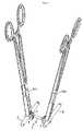
- FIG. 6shows a perspective view of an osteosynthesis system according to the invention fitted in a preliminary manner and held with the aid of a gripping forceps;
- FIG. 7shows a detail from FIG. 6 ;
- FIGS. 8 and 9show two perspective views of the use of the forceps with which it is possible to hold the hook on the correction rod as long as the clamping screw is not completely screwed in.
- the transverse connection element ( 1 )has a general dumbbell or half-dumbbell shape. It is intended to link the longitudinal connection elements formed by rods. It has a median cylindrical segment forming a transverse rod ( 2 ) continued at one end or at each end ( 3 ) by a hemispherical part.
- the transverse rod ( 2 )can be rectilinear or, by contrast, arched in order to permit easier adaptation to the anatomy of the patient, for example in an omega shape. It has a circular or any other cross section.
- the spherical ends ( 3 ) of the transverse connection elementcome into contact with longitudinal connection elements, ensuring the correction of the spine and its realignment, as is represented in FIGS. 4 and 5 .
- the connector ( 5 )is formed by a nut shown in FIG. 2 . It has a first semicylindrical seat ( 9 ) oriented substantially along a first axis ( 20 ), in order to receive a correction rod ( 4 ) of circular cross section.
- the connector ( 5 )has a second seat ( 11 ) with an axis ( 21 ) substantially perpendicular to the first axis ( 20 ), this seat ( 11 ) opening into the first seat ( 9 ) and being intended to receive a substantially spherical end ( 3 ) of the transverse rod ( 2 ) of the transverse connection element ( 1 ).
- the second seat ( 11 )has a tapped hole ( 8 ) intended to receive a clamping screw ( 7 ) in such a way as to rigidly secure the whole system.
- the tapped hole ( 8 )has an axis ( 23 ) oriented substantially perpendicular to the axis ( 21 ) of the second seat ( 11 ).
- This same connectorcan also receive on its facets, for example on the lateral face ( 6 ), grip holes in order to facilitate the manipulation of the connector, or even the whole of the transverse connection system.
- the first semicylindrical seat ( 9 )forms a groove receiving the longitudinal connection element.
- the correction rod ( 4 )is preferably a posterior rod or circular connection rod, which permits rotation thereof about its axis.
- This correction rod ( 4 )is joined to the spine by way of bone implants. These implants are formed by hooks, pedicle screws or plates for fixing to the sacrum.
- the connector ( 5 )exerts a load on the correction rod ( 4 ) in a direction posterior to the patient, which represents in this case the transverse connection element.
- the connector ( 5 )has a tapped hole ( 8 ) off-centered in relation to the axis ( 20 ) of the rod ( 4 ). This tapped hole ( 8 ) has a first function which is to receive the clamping screw ( 7 ) which locks the system.
- the cross section of the bore of the tapped hole ( 8 )is at least equal to the cross section of the spherical end ( 3 ) and merges into the opening of the second conical seat ( 11 ) intended for the passage of the transverse rod ( 2 ) of the transverse component.
- the second seat ( 11 )has a substantially semicylindrical shape along the axis ( 23 ) of the tapped hole ( 8 ).
- the semicylindrical shape of the second seatpreferably extends transversely at an angle of more than 180° and approximately 240°, in such a way as to promote the stability of the transverse rod in translation along its axis.
- the tightening of the clamping screw ( 7 )means that the end of the screw ( 7 ) bears on the spherical end ( 3 ) of the transverse component, this spherical end ( 3 ) coming to bear on the correction rod ( 4 ). It thus ensures that the rod ( 4 ) is locked in its semicylindrical seat. The tightening of the screw ( 7 ) thus ensures simultaneous locking of all the components passing through the connector.
- the conical shape of the second seat ( 11 )permits a clearance of the transverse component, as is represented in FIGS. 4 and 5 .
Landscapes
- Health & Medical Sciences (AREA)
- Orthopedic Medicine & Surgery (AREA)
- Life Sciences & Earth Sciences (AREA)
- Neurology (AREA)
- Surgery (AREA)
- Heart & Thoracic Surgery (AREA)
- Engineering & Computer Science (AREA)
- Biomedical Technology (AREA)
- Nuclear Medicine, Radiotherapy & Molecular Imaging (AREA)
- Medical Informatics (AREA)
- Molecular Biology (AREA)
- Animal Behavior & Ethology (AREA)
- General Health & Medical Sciences (AREA)
- Public Health (AREA)
- Veterinary Medicine (AREA)
- Surgical Instruments (AREA)
Abstract
Description
- a body;
- a passage defined by edge portions in said body for receiving the transverse rod, said passage having a first height at least equal to the thickness of the transverse rod, extending along the entire length of said body, opening freely out at one end and terminating at one end in an aperture defined in said body, and having a second height exceeding the thickness of the transverse rod;
- a curved strip portion extending from said body so that a correction rod can lodge therein, said aperture being provided in a connection zone between said body and said curved strip portion;
- a tapped hole defined in said body, which hole opens into said passage and is positioned in such a way that the axis of said tapped hole is in proximity to a free end portion of said curved strip portion;
- a clamping screw inserted via a screwthread into said tapped hole in order to clamp a transverse rod in said passage on a correction rod lodged in said curved strip portion;
- by which means the clamping screw, when it clamps said transverse rod, exerts a clamping force along a line which is offset in proximity to the free end portion of said curved strip portion in relation to the central axis of the correction rod in such a way as to cause a pivoting movement of the transverse rod about said correction rod.
- Positioning of a hook without its clamping screw on each of the correction rods (4), then insertion of the transverse rod (2) of general dumbbell shape and with a length adapted to the distance between the axes of said rods through the second seat (11) of each connector, then insertion and tightening of the clamping screws (7) on the connector in the tapped hole (8) provided for this purpose, for rigid connection of the assembly on the rods.
- Positioning of the pre-fitted system, the clamping screws (7) each just being introduced into the tapped holes (8) provided for this purpose, but not tightened, in such a way as to leave possible the introduction of the correction rods (4) into the first seats (9) of the hooks.
- A gripping forceps (30) of the scissor type, as is illustrated in
FIGS. 6 and 7 . This forceps allows access for the passage of the correction rod, and also access to the tapped hole for introduction and tightening of the clamping screw (7). This gripping forceps (30) bears directly on the lateral faces (6) of the connector (5) or uses grip holes formed for this purpose on these faces. - A distraction or compression forceps for defining the distance between the axes of the correction rods (4) (not shown).
- A forceps (40) with which it is possible to hold the hook on the correction rod (4) without tightening the clamping screw (7), as is illustrated in
FIG. 8 in the open position and inFIG. 9 in the closed position. This forceps (40) bears directly on the lateral faces (6) of the connector (5) or uses grip holes formed for this purpose on these faces. It comprises a rod with rabbet (41) which is curved (31) and articulated relative to the forceps in order to permit the correction rod (4) to be maintained in the closed position.
- A gripping forceps (30) of the scissor type, as is illustrated in
Claims (9)
Priority Applications (1)
| Application Number | Priority Date | Filing Date | Title |
|---|---|---|---|
| US10/109,275US7122036B2 (en) | 1999-07-01 | 2002-03-27 | Connector for an osteosynthesis system intended to provide a connection between two rods of a spinal osteosynthesis system, osteosynthesis system using such a connector, and method of implanting such an osteosynthesis system |
Applications Claiming Priority (4)
| Application Number | Priority Date | Filing Date | Title |
|---|---|---|---|
| FR99/08496 | 1999-07-01 | ||
| FR9908496AFR2795622B1 (en) | 1999-07-01 | 1999-07-01 | CONNECTOR FOR OSTEOSYNTHESIS SYSTEM FOR PROVIDING A RIGID LINK BETWEEN TWO RODS OF A SPINAL OSTEOSYNTHESIS SYSTEM, OSTEOSYNTHESIS SYSTEM USING SUCH CONNECTOR |
| US1980702A | 2002-03-25 | 2002-03-25 | |
| US10/109,275US7122036B2 (en) | 1999-07-01 | 2002-03-27 | Connector for an osteosynthesis system intended to provide a connection between two rods of a spinal osteosynthesis system, osteosynthesis system using such a connector, and method of implanting such an osteosynthesis system |
Related Parent Applications (2)
| Application Number | Title | Priority Date | Filing Date |
|---|---|---|---|
| US10019807Continuation-In-Part | 2001-12-28 | ||
| US1980702AContinuation-In-Part | 1999-07-01 | 2002-03-25 |
Publications (2)
| Publication Number | Publication Date |
|---|---|
| US20020169448A1 US20020169448A1 (en) | 2002-11-14 |
| US7122036B2true US7122036B2 (en) | 2006-10-17 |
Family
ID=26235018
Family Applications (1)
| Application Number | Title | Priority Date | Filing Date |
|---|---|---|---|
| US10/109,275Expired - LifetimeUS7122036B2 (en) | 1999-07-01 | 2002-03-27 | Connector for an osteosynthesis system intended to provide a connection between two rods of a spinal osteosynthesis system, osteosynthesis system using such a connector, and method of implanting such an osteosynthesis system |
Country Status (1)
| Country | Link |
|---|---|
| US (1) | US7122036B2 (en) |
Cited By (37)
| Publication number | Priority date | Publication date | Assignee | Title |
|---|---|---|---|---|
| US20050149019A1 (en)* | 2003-12-19 | 2005-07-07 | Sasing Jude L. | Transverse connector for rod-based spinal implants |
| US20060084978A1 (en)* | 2004-09-30 | 2006-04-20 | Mokhtar Mourad B | Spinal fixation system and method |
| US20090105765A1 (en)* | 2007-10-23 | 2009-04-23 | Intrepid Orthopedics, Llc | Spinal rod cross connector |
| US20090234390A1 (en)* | 2008-03-17 | 2009-09-17 | Partnership Of David A. Poirier And Robert A. Rovner | Implantable spinal fixation crosslink |
| US7628799B2 (en) | 2005-08-23 | 2009-12-08 | Aesculap Ag & Co. Kg | Rod to rod connector |
| US20100049252A1 (en)* | 2008-08-21 | 2010-02-25 | Southern Spine, Llc | Transverse Connector Device for Extending an Existing Spinal Fixation System |
| US20100057131A1 (en)* | 2008-08-29 | 2010-03-04 | Abbott Spine Inc. | Polyaxial transverse connector |
| US7744632B2 (en) | 2006-12-20 | 2010-06-29 | Aesculap Implant Systems, Inc. | Rod to rod connector |
| US20100274286A1 (en)* | 2009-04-23 | 2010-10-28 | Spinal Elements, Inc. | Transverse connectors |
| US20110046675A1 (en)* | 2009-08-21 | 2011-02-24 | K2M, Inc. | Transverse rod connector |
| US20110137345A1 (en)* | 2009-03-18 | 2011-06-09 | Caleb Stoll | Posterior lumbar fusion |
| US7959653B2 (en) | 2004-09-03 | 2011-06-14 | Lanx, Inc. | Spinal rod cross connector |
| US8246657B1 (en) | 2009-06-29 | 2012-08-21 | Nuvasive, Inc. | Spinal cross connector |
| US8313515B2 (en) | 2007-06-15 | 2012-11-20 | Rachiotek, Llc | Multi-level spinal stabilization system |
| US8480712B1 (en) | 2004-01-06 | 2013-07-09 | Nuvasive, Inc. | System and method for performing spinal fixation |
| US20140128918A1 (en)* | 2012-11-06 | 2014-05-08 | Michael Harper | Polyaxial Cross Connector |
| US8771319B2 (en) | 2012-04-16 | 2014-07-08 | Aesculap Implant Systems, Llc | Rod to rod cross connector |
| US8828056B2 (en) | 2012-04-16 | 2014-09-09 | Aesculap Implant Systems, Llc | Rod to rod cross connector |
| US8920471B2 (en) | 2010-07-12 | 2014-12-30 | K2M, Inc. | Transverse connector |
| US8998961B1 (en) | 2009-02-26 | 2015-04-07 | Lanx, Inc. | Spinal rod connector and methods |
| US9060813B1 (en) | 2008-02-29 | 2015-06-23 | Nuvasive, Inc. | Surgical fixation system and related methods |
| US9198696B1 (en) | 2010-05-27 | 2015-12-01 | Nuvasive, Inc. | Cross-connector and related methods |
| US9247964B1 (en) | 2011-03-01 | 2016-02-02 | Nuasive, Inc. | Spinal Cross-connector |
| US9339309B1 (en) | 2012-10-11 | 2016-05-17 | Nuvasive, Inc. | Systems and methods for inserting cross-connectors |
| US9381044B2 (en) | 2010-01-26 | 2016-07-05 | Pioneer Surgical Technology, Inc. | Posterior spinal stabilization plate device |
| US9387013B1 (en) | 2011-03-01 | 2016-07-12 | Nuvasive, Inc. | Posterior cervical fixation system |
| WO2017011446A1 (en)* | 2015-07-15 | 2017-01-19 | Warsaw Orthopedic, Inc. | Surgical adaptor and method |
| US9763703B2 (en) | 2015-05-05 | 2017-09-19 | Degen Medical, Inc. | Cross connectors, kits, and methods |
| US10238432B2 (en) | 2017-02-10 | 2019-03-26 | Medos International Sàrl | Tandem rod connectors and related methods |
| US10321939B2 (en) | 2016-05-18 | 2019-06-18 | Medos International Sarl | Implant connectors and related methods |
| US10398476B2 (en) | 2016-12-13 | 2019-09-03 | Medos International Sàrl | Implant adapters and related methods |
| US10492835B2 (en) | 2016-12-19 | 2019-12-03 | Medos International Sàrl | Offset rods, offset rod connectors, and related methods |
| US10517647B2 (en) | 2016-05-18 | 2019-12-31 | Medos International Sarl | Implant connectors and related methods |
| US10561454B2 (en) | 2017-03-28 | 2020-02-18 | Medos International Sarl | Articulating implant connectors and related methods |
| US10966761B2 (en) | 2017-03-28 | 2021-04-06 | Medos International Sarl | Articulating implant connectors and related methods |
| US11076890B2 (en) | 2017-12-01 | 2021-08-03 | Medos International Sàrl | Rod-to-rod connectors having robust rod closure mechanisms and related methods |
| US11331125B1 (en) | 2021-10-07 | 2022-05-17 | Ortho Inventions, Llc | Low profile rod-to-rod coupler |
Families Citing this family (49)
| Publication number | Priority date | Publication date | Assignee | Title |
|---|---|---|---|---|
| US6283967B1 (en)* | 1999-12-17 | 2001-09-04 | Synthes (U.S.A.) | Transconnector for coupling spinal rods |
| DE10101478C2 (en)* | 2001-01-12 | 2003-03-27 | Biedermann Motech Gmbh | connecting element |
| US7066938B2 (en) | 2002-09-09 | 2006-06-27 | Depuy Spine, Inc. | Snap-on spinal rod connector |
| WO2004084742A1 (en) | 2003-03-24 | 2004-10-07 | Theken Surgical Llc | Spinal implant adjustment device |
| US7481827B2 (en)* | 2003-10-09 | 2009-01-27 | Synthes (U.S.A.) | Linking transconnector for coupling spinal rods |
| US7744633B2 (en) | 2003-10-22 | 2010-06-29 | Pioneer Surgical Technology, Inc. | Crosslink for securing spinal rods |
| US11419642B2 (en) | 2003-12-16 | 2022-08-23 | Medos International Sarl | Percutaneous access devices and bone anchor assemblies |
| US7666188B2 (en)* | 2003-12-16 | 2010-02-23 | Depuy Spine, Inc. | Methods and devices for spinal fixation element placement |
| US7527638B2 (en) | 2003-12-16 | 2009-05-05 | Depuy Spine, Inc. | Methods and devices for minimally invasive spinal fixation element placement |
| US7179261B2 (en) | 2003-12-16 | 2007-02-20 | Depuy Spine, Inc. | Percutaneous access devices and bone anchor assemblies |
| US7476240B2 (en)* | 2004-02-06 | 2009-01-13 | Depuy Spine, Inc. | Devices and methods for inserting a spinal fixation element |
| US7547318B2 (en)* | 2004-03-19 | 2009-06-16 | Depuy Spine, Inc. | Spinal fixation element and methods |
| US7717939B2 (en) | 2004-03-31 | 2010-05-18 | Depuy Spine, Inc. | Rod attachment for head to head cross connector |
| US7645294B2 (en) | 2004-03-31 | 2010-01-12 | Depuy Spine, Inc. | Head-to-head connector spinal fixation system |
| US7491207B2 (en)* | 2004-04-12 | 2009-02-17 | Synthes Usa, Llc | Rod persuader |
| US7544208B1 (en) | 2004-05-03 | 2009-06-09 | Theken Spine, Llc | Adjustable corpectomy apparatus |
| BRPI0418941A (en)* | 2004-07-06 | 2007-12-04 | Synthes Gmbh | surgical instrument for forcing a longitudinal spinal rod into a bone fixator |
| AU2005277363A1 (en)* | 2004-08-18 | 2006-03-02 | Fsi Acquisition Sub, Llc | Adjacent level facet arthroplasty devices, spine stabilization systems, and methods |
| US7717938B2 (en) | 2004-08-27 | 2010-05-18 | Depuy Spine, Inc. | Dual rod cross connectors and inserter tools |
| US20070225713A1 (en)* | 2004-10-20 | 2007-09-27 | Moti Altarac | Systems and methods for posterior dynamic stabilization of the spine |
| US7879074B2 (en) | 2005-09-27 | 2011-02-01 | Depuy Spine, Inc. | Posterior dynamic stabilization systems and methods |
| EP1931269A1 (en)* | 2005-10-07 | 2008-06-18 | Alphatec Spine, Inc. | Transverse rod connector |
| US20070173829A1 (en)* | 2006-01-23 | 2007-07-26 | Sdgi Holdings, Inc. | Devices and methods for connecting vertebral rods |
| WO2007114834A1 (en) | 2006-04-05 | 2007-10-11 | Dong Myung Jeon | Multi-axial, double locking bone screw assembly |
| WO2008008853A2 (en)* | 2006-07-11 | 2008-01-17 | Pioneer Surgical Technology, Inc. | Transverse connector |
| US7922746B2 (en)* | 2006-08-31 | 2011-04-12 | Warsaw Orthopedic, Inc. | Spinal rod extenders and methods of use |
| CA2664591C (en) | 2006-09-26 | 2014-12-02 | Synthes Usa, Llc | Transconnector |
| US7918857B2 (en) | 2006-09-26 | 2011-04-05 | Depuy Spine, Inc. | Minimally invasive bone anchor extensions |
| US8075594B2 (en)* | 2006-10-06 | 2011-12-13 | Alphatec Spine, Inc | Multi-axial transverse rod connector |
| US8361117B2 (en) | 2006-11-08 | 2013-01-29 | Depuy Spine, Inc. | Spinal cross connectors |
| US8617213B2 (en)* | 2007-06-08 | 2013-12-31 | K2M, Inc. | Low profile transverse connector |
| US8048129B2 (en)* | 2007-08-15 | 2011-11-01 | Zimmer Spine, Inc. | MIS crosslink apparatus and methods for spinal implant |
| US8414588B2 (en) | 2007-10-04 | 2013-04-09 | Depuy Spine, Inc. | Methods and devices for minimally invasive spinal connection element delivery |
| US20090112266A1 (en)* | 2007-10-25 | 2009-04-30 | Industrial Technology Research Institute | Spinal dynamic stabilization device |
| EP2484300B1 (en)* | 2008-09-05 | 2015-05-20 | Biedermann Technologies GmbH & Co. KG | Stabilization device for bones, in particular for the spinal column |
| US8372120B2 (en) | 2009-05-20 | 2013-02-12 | Spine Wave, Inc. | Multi-axial cross connector |
| AU2014277759B2 (en)* | 2009-08-21 | 2015-11-26 | K2M, Inc. | Transverse rod connector |
| US8568456B2 (en) | 2009-09-21 | 2013-10-29 | Globus Medical, Inc. | Transverse connector having a locking element for capturing multiple rods |
| US8777996B2 (en) | 2010-07-12 | 2014-07-15 | Globus Medical, Inc. | Interspinous ligament transverse connector |
| US8672978B2 (en) | 2011-03-04 | 2014-03-18 | Zimmer Spine, Inc. | Transverse connector |
| WO2014172632A2 (en) | 2011-11-16 | 2014-10-23 | Kspine, Inc. | Spinal correction and secondary stabilization |
| US9451987B2 (en) | 2011-11-16 | 2016-09-27 | K2M, Inc. | System and method for spinal correction |
| US9468469B2 (en) | 2011-11-16 | 2016-10-18 | K2M, Inc. | Transverse coupler adjuster spinal correction systems and methods |
| US20140277163A1 (en)* | 2013-03-15 | 2014-09-18 | Ryan Kretzer | Reinforcement systems for spine stabilization constructs |
| US9468471B2 (en) | 2013-09-17 | 2016-10-18 | K2M, Inc. | Transverse coupler adjuster spinal correction systems and methods |
| DE102015205362B4 (en)* | 2015-03-24 | 2017-04-13 | Silony Medical International AG | Instrument for connecting a correction rod to a bone screw |
| US10905473B2 (en)* | 2016-02-15 | 2021-02-02 | Asro Medical | Transverse, and surgical instrument |
| DE102019005376A1 (en)* | 2019-07-30 | 2021-02-04 | Signus Medizintechnik Gmbh | CONNECTING DEVICE FOR SPINE SUPPORT |
| NL2026643B1 (en)* | 2020-10-08 | 2022-06-07 | Umc Utrecht Holding Bv | Connector for spinal correction |
Citations (28)
| Publication number | Priority date | Publication date | Assignee | Title |
|---|---|---|---|---|
| US4604995A (en)* | 1984-03-30 | 1986-08-12 | Stephens David C | Spinal stabilizer |
| EP0446092A1 (en) | 1990-03-08 | 1991-09-11 | Societe De Fabrication De Materiel Orthopedique Sofamor | Device for rigid transverse connection of two spinal osteosynthesis rods |
| US5207678A (en)* | 1989-07-20 | 1993-05-04 | Prufer | Pedicle screw and receiver member therefore |
| US5429637A (en)* | 1991-11-08 | 1995-07-04 | Hardy; Jean M. | External modular fixator for immobilization of a fracture |
| EP0676177A2 (en) | 1994-03-09 | 1995-10-11 | Acromed Corporation | Transverse connector for spinal column devices |
| US5480401A (en)* | 1993-02-17 | 1996-01-02 | Psi | Extra-discal inter-vertebral prosthesis for controlling the variations of the inter-vertebral distance by means of a double damper |
| EP0689799A1 (en) | 1994-06-28 | 1996-01-03 | Acromed Corporation | Transverse connector for spinal column corrective devices |
| US5514132A (en)* | 1993-01-19 | 1996-05-07 | Jbs S.A. | Spinal osteosynthesis device |
| US5534002A (en)* | 1993-01-04 | 1996-07-09 | Danek Medical, Inc. | Spinal fixation system |
| US5540688A (en)* | 1991-05-30 | 1996-07-30 | Societe "Psi" | Intervertebral stabilization device incorporating dampers |
| US5569246A (en)* | 1993-12-28 | 1996-10-29 | Asahi Kogaku Kogyo Kabushiki Kaisha | Fixing instrument for spinal fusion members |
| US5584831A (en)* | 1993-07-09 | 1996-12-17 | September 28, Inc. | Spinal fixation device and method |
| US5601552A (en)* | 1994-03-18 | 1997-02-11 | Sofamor, S.N.C. | Fixing device for a rigid transverse connection device between rods of a spinal osteosynthesis system |
| US5624441A (en)* | 1993-08-19 | 1997-04-29 | Danek Medical, Inc. | Attachment plate for top-tightening clamp assembly in a spinal fixation system |
| US5720751A (en)* | 1996-11-27 | 1998-02-24 | Jackson; Roger P. | Tools for use in seating spinal rods in open ended implants |
| US5755796A (en)* | 1996-06-06 | 1998-05-26 | Ibo; Ivo | Prosthesis of the cervical intervertebralis disk |
| US5776135A (en)* | 1996-12-23 | 1998-07-07 | Third Millennium Engineering, Llc | Side mounted polyaxial pedicle screw |
| US5800548A (en)* | 1996-03-05 | 1998-09-01 | Bruno Franck | Device for transverse spinal connection |
| US5947967A (en)* | 1997-10-22 | 1999-09-07 | Sdgt Holdings, Inc. | Variable angle connector |
| US5964769A (en)* | 1997-08-26 | 1999-10-12 | Spinal Concepts, Inc. | Surgical cable system and method |
| US6099528A (en)* | 1997-05-29 | 2000-08-08 | Sofamor S.N.C. | Vertebral rod for spinal osteosynthesis instrumentation and osteosynthesis instrumentation, including said rod |
| US6187005B1 (en)* | 1998-09-11 | 2001-02-13 | Synthes (Usa) | Variable angle spinal fixation system |
| US6290196B1 (en)* | 1998-05-16 | 2001-09-18 | Aesculap Ag & Co. Kg | Holding device for a surgical instrument |
| US20020138077A1 (en)* | 2001-03-26 | 2002-09-26 | Ferree Bret A. | Spinal alignment apparatus and methods |
| US20020143327A1 (en)* | 2001-03-27 | 2002-10-03 | Endius Incorporated | Transverse connector for use in spinal corrective surgery |
| US6475218B2 (en)* | 2000-06-30 | 2002-11-05 | Sofamor, S.N.C. | Spinal implant for an osteosynthesis device |
| US20030045874A1 (en)* | 2001-08-31 | 2003-03-06 | Thomas James C. | Transverse connector assembly for spine fixation system |
| US6554831B1 (en)* | 2000-09-01 | 2003-04-29 | Hopital Sainte-Justine | Mobile dynamic system for treating spinal disorder |
- 2002
- 2002-03-27USUS10/109,275patent/US7122036B2/ennot_activeExpired - Lifetime
Patent Citations (29)
| Publication number | Priority date | Publication date | Assignee | Title |
|---|---|---|---|---|
| US4604995A (en)* | 1984-03-30 | 1986-08-12 | Stephens David C | Spinal stabilizer |
| US5207678A (en)* | 1989-07-20 | 1993-05-04 | Prufer | Pedicle screw and receiver member therefore |
| EP0446092A1 (en) | 1990-03-08 | 1991-09-11 | Societe De Fabrication De Materiel Orthopedique Sofamor | Device for rigid transverse connection of two spinal osteosynthesis rods |
| US5540688A (en)* | 1991-05-30 | 1996-07-30 | Societe "Psi" | Intervertebral stabilization device incorporating dampers |
| US5429637A (en)* | 1991-11-08 | 1995-07-04 | Hardy; Jean M. | External modular fixator for immobilization of a fracture |
| US5534002A (en)* | 1993-01-04 | 1996-07-09 | Danek Medical, Inc. | Spinal fixation system |
| US5514132A (en)* | 1993-01-19 | 1996-05-07 | Jbs S.A. | Spinal osteosynthesis device |
| US5480401A (en)* | 1993-02-17 | 1996-01-02 | Psi | Extra-discal inter-vertebral prosthesis for controlling the variations of the inter-vertebral distance by means of a double damper |
| US6468276B1 (en)* | 1993-07-09 | 2002-10-22 | Mckay Douglas William | Spinal fixation device and method |
| US5584831A (en)* | 1993-07-09 | 1996-12-17 | September 28, Inc. | Spinal fixation device and method |
| US5624441A (en)* | 1993-08-19 | 1997-04-29 | Danek Medical, Inc. | Attachment plate for top-tightening clamp assembly in a spinal fixation system |
| US5569246A (en)* | 1993-12-28 | 1996-10-29 | Asahi Kogaku Kogyo Kabushiki Kaisha | Fixing instrument for spinal fusion members |
| EP0676177A2 (en) | 1994-03-09 | 1995-10-11 | Acromed Corporation | Transverse connector for spinal column devices |
| US5601552A (en)* | 1994-03-18 | 1997-02-11 | Sofamor, S.N.C. | Fixing device for a rigid transverse connection device between rods of a spinal osteosynthesis system |
| EP0689799A1 (en) | 1994-06-28 | 1996-01-03 | Acromed Corporation | Transverse connector for spinal column corrective devices |
| US5800548A (en)* | 1996-03-05 | 1998-09-01 | Bruno Franck | Device for transverse spinal connection |
| US5755796A (en)* | 1996-06-06 | 1998-05-26 | Ibo; Ivo | Prosthesis of the cervical intervertebralis disk |
| US5720751A (en)* | 1996-11-27 | 1998-02-24 | Jackson; Roger P. | Tools for use in seating spinal rods in open ended implants |
| US5776135A (en)* | 1996-12-23 | 1998-07-07 | Third Millennium Engineering, Llc | Side mounted polyaxial pedicle screw |
| US6099528A (en)* | 1997-05-29 | 2000-08-08 | Sofamor S.N.C. | Vertebral rod for spinal osteosynthesis instrumentation and osteosynthesis instrumentation, including said rod |
| US5964769A (en)* | 1997-08-26 | 1999-10-12 | Spinal Concepts, Inc. | Surgical cable system and method |
| US5947967A (en)* | 1997-10-22 | 1999-09-07 | Sdgt Holdings, Inc. | Variable angle connector |
| US6290196B1 (en)* | 1998-05-16 | 2001-09-18 | Aesculap Ag & Co. Kg | Holding device for a surgical instrument |
| US6187005B1 (en)* | 1998-09-11 | 2001-02-13 | Synthes (Usa) | Variable angle spinal fixation system |
| US6475218B2 (en)* | 2000-06-30 | 2002-11-05 | Sofamor, S.N.C. | Spinal implant for an osteosynthesis device |
| US6554831B1 (en)* | 2000-09-01 | 2003-04-29 | Hopital Sainte-Justine | Mobile dynamic system for treating spinal disorder |
| US20020138077A1 (en)* | 2001-03-26 | 2002-09-26 | Ferree Bret A. | Spinal alignment apparatus and methods |
| US20020143327A1 (en)* | 2001-03-27 | 2002-10-03 | Endius Incorporated | Transverse connector for use in spinal corrective surgery |
| US20030045874A1 (en)* | 2001-08-31 | 2003-03-06 | Thomas James C. | Transverse connector assembly for spine fixation system |
Cited By (71)
| Publication number | Priority date | Publication date | Assignee | Title |
|---|---|---|---|---|
| US7569069B2 (en)* | 2003-12-19 | 2009-08-04 | Orthopaedic International, Inc. | Transverse connector for rod-based spinal implants |
| US8137388B2 (en) | 2003-12-19 | 2012-03-20 | Orthopaedic International, Inc. | Transverse connector for rod-based spinal implants |
| US20090312799A1 (en)* | 2003-12-19 | 2009-12-17 | Sasing Jude L | Transverse connector for rod-based spinal implants |
| US20050149019A1 (en)* | 2003-12-19 | 2005-07-07 | Sasing Jude L. | Transverse connector for rod-based spinal implants |
| US8480712B1 (en) | 2004-01-06 | 2013-07-09 | Nuvasive, Inc. | System and method for performing spinal fixation |
| US7959653B2 (en) | 2004-09-03 | 2011-06-14 | Lanx, Inc. | Spinal rod cross connector |
| US20060084978A1 (en)* | 2004-09-30 | 2006-04-20 | Mokhtar Mourad B | Spinal fixation system and method |
| US7628799B2 (en) | 2005-08-23 | 2009-12-08 | Aesculap Ag & Co. Kg | Rod to rod connector |
| US7744632B2 (en) | 2006-12-20 | 2010-06-29 | Aesculap Implant Systems, Inc. | Rod to rod connector |
| US8313515B2 (en) | 2007-06-15 | 2012-11-20 | Rachiotek, Llc | Multi-level spinal stabilization system |
| US20090105765A1 (en)* | 2007-10-23 | 2009-04-23 | Intrepid Orthopedics, Llc | Spinal rod cross connector |
| US9474554B2 (en) | 2007-10-23 | 2016-10-25 | Lee A. Strnad | Spinal rod cross connector |
| US9060813B1 (en) | 2008-02-29 | 2015-06-23 | Nuvasive, Inc. | Surgical fixation system and related methods |
| US20090234390A1 (en)* | 2008-03-17 | 2009-09-17 | Partnership Of David A. Poirier And Robert A. Rovner | Implantable spinal fixation crosslink |
| US8419771B2 (en) | 2008-03-17 | 2013-04-16 | Partnership Of David A. Poirier And Robert A. Rovner | Implantable spinal fixation crosslink |
| US20100049252A1 (en)* | 2008-08-21 | 2010-02-25 | Southern Spine, Llc | Transverse Connector Device for Extending an Existing Spinal Fixation System |
| US8167908B2 (en)* | 2008-08-29 | 2012-05-01 | Zimmer Spine, Inc. | Polyaxial transverse connector |
| US20100057131A1 (en)* | 2008-08-29 | 2010-03-04 | Abbott Spine Inc. | Polyaxial transverse connector |
| US8998961B1 (en) | 2009-02-26 | 2015-04-07 | Lanx, Inc. | Spinal rod connector and methods |
| US20110137345A1 (en)* | 2009-03-18 | 2011-06-09 | Caleb Stoll | Posterior lumbar fusion |
| US9131964B2 (en) | 2009-04-23 | 2015-09-15 | Spinal Elements, Inc. | Transverse connectors |
| US8828055B2 (en) | 2009-04-23 | 2014-09-09 | Spinal Elements, Inc. | Transverse connectors |
| US20100274286A1 (en)* | 2009-04-23 | 2010-10-28 | Spinal Elements, Inc. | Transverse connectors |
| US8246657B1 (en) | 2009-06-29 | 2012-08-21 | Nuvasive, Inc. | Spinal cross connector |
| US8961565B2 (en) | 2009-08-21 | 2015-02-24 | K2M, Inc. | Transverse rod connector |
| US9468472B2 (en) | 2009-08-21 | 2016-10-18 | K2M, Inc. | Transverse rod connector |
| US9271763B2 (en) | 2009-08-21 | 2016-03-01 | K2M, Llc | Transverse rod connector |
| US20110046675A1 (en)* | 2009-08-21 | 2011-02-24 | K2M, Inc. | Transverse rod connector |
| US10022160B2 (en) | 2010-01-26 | 2018-07-17 | Pioneer Surgical Technology, Inc. | Posterior spinal stabilization plate device |
| US9381044B2 (en) | 2010-01-26 | 2016-07-05 | Pioneer Surgical Technology, Inc. | Posterior spinal stabilization plate device |
| US9198696B1 (en) | 2010-05-27 | 2015-12-01 | Nuvasive, Inc. | Cross-connector and related methods |
| US8920471B2 (en) | 2010-07-12 | 2014-12-30 | K2M, Inc. | Transverse connector |
| US9504500B2 (en) | 2010-07-12 | 2016-11-29 | K2M, Inc. | Transverse connector |
| US9827021B2 (en) | 2010-07-12 | 2017-11-28 | K2M, Inc. | Transverse connector |
| US9387013B1 (en) | 2011-03-01 | 2016-07-12 | Nuvasive, Inc. | Posterior cervical fixation system |
| US10368918B2 (en) | 2011-03-01 | 2019-08-06 | Nuvasive, Inc. | Posterior cervical fixation system |
| US9247964B1 (en) | 2011-03-01 | 2016-02-02 | Nuasive, Inc. | Spinal Cross-connector |
| US11123110B2 (en) | 2011-03-01 | 2021-09-21 | Nuvasive, Inc. | Posterior cervical fixation system |
| US10779865B2 (en) | 2011-03-01 | 2020-09-22 | Nuvasive, Inc. | Spinal cross connector |
| US11478282B2 (en) | 2011-03-01 | 2022-10-25 | Nuvasive, Inc. | Spinal cross connector |
| US10136925B2 (en) | 2011-03-01 | 2018-11-27 | Nuvasive, Inc. | Spinal cross-connector |
| US9956009B1 (en) | 2011-03-01 | 2018-05-01 | Nuvasive, Inc. | Posterior cervical fixation system |
| US9770269B1 (en) | 2011-03-01 | 2017-09-26 | Nuvasive, Inc. | Spinal Cross-connector |
| US8771319B2 (en) | 2012-04-16 | 2014-07-08 | Aesculap Implant Systems, Llc | Rod to rod cross connector |
| US8828056B2 (en) | 2012-04-16 | 2014-09-09 | Aesculap Implant Systems, Llc | Rod to rod cross connector |
| US9339309B1 (en) | 2012-10-11 | 2016-05-17 | Nuvasive, Inc. | Systems and methods for inserting cross-connectors |
| US20140128918A1 (en)* | 2012-11-06 | 2014-05-08 | Michael Harper | Polyaxial Cross Connector |
| US9517090B2 (en) | 2012-11-06 | 2016-12-13 | Globus Medical, Inc. | Polyaxial cross connector |
| US9072547B2 (en)* | 2012-11-06 | 2015-07-07 | Globus Medical, Inc. | Polyaxial cross connector |
| US9763703B2 (en) | 2015-05-05 | 2017-09-19 | Degen Medical, Inc. | Cross connectors, kits, and methods |
| WO2017011446A1 (en)* | 2015-07-15 | 2017-01-19 | Warsaw Orthopedic, Inc. | Surgical adaptor and method |
| US11622757B2 (en) | 2015-07-15 | 2023-04-11 | Warsaw Orthopedics Inc. | Surgical adaptor and method |
| US10799226B2 (en) | 2015-07-15 | 2020-10-13 | Warsaw Orthopedic, Inc. | Surgical adaptor and method |
| US10321939B2 (en) | 2016-05-18 | 2019-06-18 | Medos International Sarl | Implant connectors and related methods |
| US10517647B2 (en) | 2016-05-18 | 2019-12-31 | Medos International Sarl | Implant connectors and related methods |
| US11058463B2 (en) | 2016-05-18 | 2021-07-13 | Medos International Sarl | Implant connectors and related methods |
| US11596451B2 (en) | 2016-05-18 | 2023-03-07 | Medos International Sarl | Implant connectors and related methods |
| US10398476B2 (en) | 2016-12-13 | 2019-09-03 | Medos International Sàrl | Implant adapters and related methods |
| US10492835B2 (en) | 2016-12-19 | 2019-12-03 | Medos International Sàrl | Offset rods, offset rod connectors, and related methods |
| US12150679B2 (en) | 2016-12-19 | 2024-11-26 | Medos International Srl | Offset rods, offset rod connectors, and related methods |
| US11160583B2 (en) | 2016-12-19 | 2021-11-02 | Medos International Sarl | Offset rods, offset rod connectors, and related methods |
| US10869695B2 (en) | 2017-02-10 | 2020-12-22 | Medos International Sarl | Tandem rod connectors and related methods |
| US11793554B2 (en) | 2017-02-10 | 2023-10-24 | Medos International Sarl | Tandem rod connectors and related methods |
| US10238432B2 (en) | 2017-02-10 | 2019-03-26 | Medos International Sàrl | Tandem rod connectors and related methods |
| US10561454B2 (en) | 2017-03-28 | 2020-02-18 | Medos International Sarl | Articulating implant connectors and related methods |
| US11382676B2 (en) | 2017-03-28 | 2022-07-12 | Medos International Sarl | Articulating implant connectors and related methods |
| US11707304B2 (en) | 2017-03-28 | 2023-07-25 | Medos International Sarl | Articulating implant connectors and related methods |
| US12059187B2 (en) | 2017-03-28 | 2024-08-13 | Medos International Sarl | Articulating implant connectors and related methods |
| US10966761B2 (en) | 2017-03-28 | 2021-04-06 | Medos International Sarl | Articulating implant connectors and related methods |
| US11076890B2 (en) | 2017-12-01 | 2021-08-03 | Medos International Sàrl | Rod-to-rod connectors having robust rod closure mechanisms and related methods |
| US11331125B1 (en) | 2021-10-07 | 2022-05-17 | Ortho Inventions, Llc | Low profile rod-to-rod coupler |
Also Published As
| Publication number | Publication date |
|---|---|
| US20020169448A1 (en) | 2002-11-14 |
Similar Documents
| Publication | Publication Date | Title |
|---|---|---|
| US7122036B2 (en) | Connector for an osteosynthesis system intended to provide a connection between two rods of a spinal osteosynthesis system, osteosynthesis system using such a connector, and method of implanting such an osteosynthesis system | |
| US6413257B1 (en) | Clamping connector for spinal fixation systems | |
| CA2562949C (en) | Head-to-head connector spinal fixation system | |
| US5562661A (en) | Top tightening bone fixation apparatus | |
| US7803174B2 (en) | Dorsal adjusting multi-rod connector | |
| US5947966A (en) | Device for linking adjacent rods in spinal instrumentation | |
| USRE39035E1 (en) | Universal coupler for spinal fixation | |
| US6402751B1 (en) | Device for linking adjacent rods in spinal instrumentation | |
| US8226689B2 (en) | Apparatus and methods for spinal implant with variable link mechanism | |
| US6610063B2 (en) | Spinal fixation system | |
| US6673073B1 (en) | Transverse connector | |
| JP3854312B2 (en) | Back vertebral surgical anchor device | |
| KR100202329B1 (en) | Spinal structure with band clamp | |
| EP1152705B1 (en) | Spinal fixation system | |
| US8262702B2 (en) | Osteosynthetic clamp for attaching a bone anchor to a support rod | |
| JPH08505784A (en) | Spinal osteosynthesis device for anterior approach | |
| KR20090009853A (en) | Connector device | |
| MXPA03001514A (en) | A surgical cross-connecting apparatus. | |
| JP4301754B2 (en) | Transverse coupler for vertebral joint system | |
| US20180289403A1 (en) | Laminar Fixation Clamp and Method |
Legal Events
| Date | Code | Title | Description |
|---|---|---|---|
| AS | Assignment | Owner name:SPINEVISION S.A., FRANCE Free format text:ASSIGNMENT OF ASSIGNORS INTEREST;ASSIGNOR:VANACKER, GERARD M.;REEL/FRAME:012907/0994 Effective date:20020404 | |
| STCF | Information on status: patent grant | Free format text:PATENTED CASE | |
| FPAY | Fee payment | Year of fee payment:4 | |
| SULP | Surcharge for late payment | ||
| FPAY | Fee payment | Year of fee payment:8 | |
| AS | Assignment | Owner name:NORGINE PHARMA, FRANCE Free format text:LIEN;ASSIGNOR:SPINEVISION;REEL/FRAME:033960/0774 Effective date:20140926 Owner name:NORGINE B.V., NETHERLANDS Free format text:LIEN;ASSIGNOR:SPINEVISION;REEL/FRAME:033960/0774 Effective date:20140926 | |
| AS | Assignment | Owner name:NORGINE B.V., NETHERLANDS Free format text:CORRECTIVE ASSIGNMENT TO CORRECT THE ASSIGNEE NAME PREVIOUSLY RECORDED AT REEL: 033960 FRAME: 0774. ASSIGNOR(S) HEREBY CONFIRMS THE ASSIGNMENT;ASSIGNOR:SPINEVISION;REEL/FRAME:034056/0330 Effective date:20140926 | |
| AS | Assignment | Owner name:NORGINE B.V., NETHERLANDS Free format text:LIEN;ASSIGNOR:SPINEVISION;REEL/FRAME:034977/0225 Effective date:20150129 | |
| AS | Assignment | Owner name:NORGINE VENTURES B.V, NETHERLANDS Free format text:ASSIGNMENT OF ASSIGNORS INTEREST;ASSIGNOR:NORGINE B.V;REEL/FRAME:038897/0605 Effective date:20160610 | |
| MAFP | Maintenance fee payment | Free format text:PAYMENT OF MAINTENANCE FEE, 12TH YEAR, LARGE ENTITY (ORIGINAL EVENT CODE: M1553) Year of fee payment:12 |