US7121991B2 - Bottom sealing assembly for cup forming machine - Google Patents
Bottom sealing assembly for cup forming machineDownload PDFInfo
- Publication number
- US7121991B2 US7121991B2US10/979,790US97979004AUS7121991B2US 7121991 B2US7121991 B2US 7121991B2US 97979004 AUS97979004 AUS 97979004AUS 7121991 B2US7121991 B2US 7121991B2
- Authority
- US
- United States
- Prior art keywords
- motor
- assembly
- barrel
- bottom sealing
- shaft
- Prior art date
- Legal status (The legal status is an assumption and is not a legal conclusion. Google has not performed a legal analysis and makes no representation as to the accuracy of the status listed.)
- Expired - Lifetime, expires
Links
- 238000007789sealingMethods0.000titleclaimsabstractdescription64
- 230000033001locomotionEffects0.000claimsabstractdescription96
- 230000008859changeEffects0.000claimsabstractdescription35
- 230000013011matingEffects0.000claimsdescription4
- 238000009987spinningMethods0.000claimsdescription3
- 230000000712assemblyEffects0.000abstractdescription7
- 238000000429assemblyMethods0.000abstractdescription7
- 239000000123paperSubstances0.000description78
- 238000012546transferMethods0.000description32
- 238000000576coating methodMethods0.000description12
- 238000010438heat treatmentMethods0.000description12
- 230000007246mechanismEffects0.000description12
- 239000011248coating agentSubstances0.000description10
- 238000002407reformingMethods0.000description9
- 230000004044responseEffects0.000description9
- 229920001169thermoplasticPolymers0.000description9
- 239000004416thermosoftening plasticSubstances0.000description9
- 239000004698PolyethyleneSubstances0.000description7
- 230000006870functionEffects0.000description7
- -1polyethylenePolymers0.000description7
- 229920000573polyethylenePolymers0.000description7
- XEEYBQQBJWHFJM-UHFFFAOYSA-NIronChemical compound[Fe]XEEYBQQBJWHFJM-UHFFFAOYSA-N0.000description4
- 230000009471actionEffects0.000description4
- 238000000034methodMethods0.000description4
- 239000011087paperboardSubstances0.000description4
- 238000005096rolling processMethods0.000description4
- 230000001133accelerationEffects0.000description3
- 238000004519manufacturing processMethods0.000description3
- 230000008569processEffects0.000description3
- 238000005520cutting processMethods0.000description2
- 230000007423decreaseEffects0.000description2
- 230000000977initiatory effectEffects0.000description2
- 229910052742ironInorganic materials0.000description2
- 230000000750progressive effectEffects0.000description2
- 229910001220stainless steelInorganic materials0.000description2
- 239000010935stainless steelSubstances0.000description2
- 239000000853adhesiveSubstances0.000description1
- 230000001070adhesive effectEffects0.000description1
- 238000005452bendingMethods0.000description1
- 238000004364calculation methodMethods0.000description1
- 230000006835compressionEffects0.000description1
- 238000007906compressionMethods0.000description1
- 230000036461convulsionEffects0.000description1
- 230000002950deficientEffects0.000description1
- 238000011161developmentMethods0.000description1
- 230000000694effectsEffects0.000description1
- 230000007613environmental effectEffects0.000description1
- 235000000396ironNutrition0.000description1
- 238000010409ironingMethods0.000description1
- 238000012423maintenanceMethods0.000description1
- 238000013178mathematical modelMethods0.000description1
- 238000012986modificationMethods0.000description1
- 230000004048modificationEffects0.000description1
- 238000012544monitoring processMethods0.000description1
- 238000012545processingMethods0.000description1
- 238000011160researchMethods0.000description1
- 230000000979retarding effectEffects0.000description1
- 230000001360synchronised effectEffects0.000description1
- 239000012815thermoplastic materialSubstances0.000description1
Images


Classifications
- B—PERFORMING OPERATIONS; TRANSPORTING
- B31—MAKING ARTICLES OF PAPER, CARDBOARD OR MATERIAL WORKED IN A MANNER ANALOGOUS TO PAPER; WORKING PAPER, CARDBOARD OR MATERIAL WORKED IN A MANNER ANALOGOUS TO PAPER
- B31F—MECHANICAL WORKING OR DEFORMATION OF PAPER, CARDBOARD OR MATERIAL WORKED IN A MANNER ANALOGOUS TO PAPER
- B31F1/00—Mechanical deformation without removing material, e.g. in combination with laminating
- B31F1/0003—Shaping by bending, folding, twisting, straightening, flattening or rim-rolling; Shaping by bending, folding or rim-rolling combined with joining; Apparatus therefor
- B31F1/0038—Rim-rolling
- B—PERFORMING OPERATIONS; TRANSPORTING
- B31—MAKING ARTICLES OF PAPER, CARDBOARD OR MATERIAL WORKED IN A MANNER ANALOGOUS TO PAPER; WORKING PAPER, CARDBOARD OR MATERIAL WORKED IN A MANNER ANALOGOUS TO PAPER
- B31B—MAKING CONTAINERS OF PAPER, CARDBOARD OR MATERIAL WORKED IN A MANNER ANALOGOUS TO PAPER
- B31B50/00—Making rigid or semi-rigid containers, e.g. boxes or cartons
- B31B50/74—Auxiliary operations
- B31B50/81—Forming or attaching accessories, e.g. opening devices, closures or tear strings
- B—PERFORMING OPERATIONS; TRANSPORTING
- B31—MAKING ARTICLES OF PAPER, CARDBOARD OR MATERIAL WORKED IN A MANNER ANALOGOUS TO PAPER; WORKING PAPER, CARDBOARD OR MATERIAL WORKED IN A MANNER ANALOGOUS TO PAPER
- B31B—MAKING CONTAINERS OF PAPER, CARDBOARD OR MATERIAL WORKED IN A MANNER ANALOGOUS TO PAPER
- B31B2105/00—Rigid or semi-rigid containers made by assembling separate sheets, blanks or webs
- B31B2105/002—Making boxes characterised by the shape of the blanks from which they are formed
- B31B2105/0022—Making boxes from tubular webs or blanks, e.g. with separate bottoms, including tube or bottom forming operations
- B—PERFORMING OPERATIONS; TRANSPORTING
- B31—MAKING ARTICLES OF PAPER, CARDBOARD OR MATERIAL WORKED IN A MANNER ANALOGOUS TO PAPER; WORKING PAPER, CARDBOARD OR MATERIAL WORKED IN A MANNER ANALOGOUS TO PAPER
- B31B—MAKING CONTAINERS OF PAPER, CARDBOARD OR MATERIAL WORKED IN A MANNER ANALOGOUS TO PAPER
- B31B2120/00—Construction of rigid or semi-rigid containers
- B31B2120/002—Construction of rigid or semi-rigid containers having contracted or rolled necks, having shoulders
- B—PERFORMING OPERATIONS; TRANSPORTING
- B31—MAKING ARTICLES OF PAPER, CARDBOARD OR MATERIAL WORKED IN A MANNER ANALOGOUS TO PAPER; WORKING PAPER, CARDBOARD OR MATERIAL WORKED IN A MANNER ANALOGOUS TO PAPER
- B31B—MAKING CONTAINERS OF PAPER, CARDBOARD OR MATERIAL WORKED IN A MANNER ANALOGOUS TO PAPER
- B31B50/00—Making rigid or semi-rigid containers, e.g. boxes or cartons
- B31B50/25—Surface scoring
- B31B50/256—Surface scoring using tools mounted on a drum
- B—PERFORMING OPERATIONS; TRANSPORTING
- B31—MAKING ARTICLES OF PAPER, CARDBOARD OR MATERIAL WORKED IN A MANNER ANALOGOUS TO PAPER; WORKING PAPER, CARDBOARD OR MATERIAL WORKED IN A MANNER ANALOGOUS TO PAPER
- B31B—MAKING CONTAINERS OF PAPER, CARDBOARD OR MATERIAL WORKED IN A MANNER ANALOGOUS TO PAPER
- B31B50/00—Making rigid or semi-rigid containers, e.g. boxes or cartons
- B31B50/26—Folding sheets, blanks or webs
- B31B50/28—Folding sheets, blanks or webs around mandrels, e.g. for forming bottoms
- B31B50/30—Folding sheets, blanks or webs around mandrels, e.g. for forming bottoms the mandrels moving
- B31B50/32—Folding sheets, blanks or webs around mandrels, e.g. for forming bottoms the mandrels moving in circular paths
- B—PERFORMING OPERATIONS; TRANSPORTING
- B31—MAKING ARTICLES OF PAPER, CARDBOARD OR MATERIAL WORKED IN A MANNER ANALOGOUS TO PAPER; WORKING PAPER, CARDBOARD OR MATERIAL WORKED IN A MANNER ANALOGOUS TO PAPER
- B31F—MECHANICAL WORKING OR DEFORMATION OF PAPER, CARDBOARD OR MATERIAL WORKED IN A MANNER ANALOGOUS TO PAPER
- B31F1/00—Mechanical deformation without removing material, e.g. in combination with laminating
- B31F1/08—Creasing
- B31F1/10—Creasing by rotary tools
Definitions
- the present inventionrelates generally to a bottom sealing assembly for a cup forming machine, and more specifically to a computer controlled bottom sealing assembly that is quantitatively controllable.
- Cup forming machines and bottom sealing assemblies thereforare well known in the art.
- Such bottom sealing assembliesare generally used seal a folded portion of a sidewall to a bottom wall to form the bottom portion of a cup during the cup forming process. While such bottom sealing assemblies according to the prior art provide a number of advantageous features, they nevertheless have certain limitations.
- the present inventionseeks to overcome certain of these limitations and other drawbacks of the prior art, and to provide new features not heretofore available. A full discussion of the features and advantages of the present invention is deferred to the following detailed description, which proceeds with reference to the accompanying drawings.
- the present inventiongenerally provides a bottom seal assembly used seal a folded portion of a sidewall to a bottom wall to form the bottom portion of a cup during the cup forming process.
- the bottom sealing assemblycomprises a mounting assembly, a linear motion assembly, a rotation assembly, and a phase change assembly.
- the mounting assemblyis secured to the cup forming machine
- the linear motion assemblyis at least partially moveably connected to the mounting assembly
- the rotation assemblyhas at least a portion thereof mounted to the linear motion assembly such that the at least a portion of the rotation assembly moves with the linear motion assembly.
- the rotation assemblyhas a shaft and a finishing tool connected to the shaft, and the finishing tool is rotated in a circle having a first radius.
- the phase change assemblyis operably connected to the shaft to manipulate the shaft to have the finishing tool rotate in a circle having a second radius that is larger than the first radius.
- the bottom sealing assemblyfurther has a tracking assembly connected to the rotation assembly.
- the tracking assemblydevelops a signal of the position of the rotation assembly and transmits the signal to the phase change assembly to control the operation thereof.
- a first motoris provided in association with the linear motion assembly to linearly move the linear motion assembly
- a second motoris provided in association with the rotation assembly to rotate a supporting component for the shaft
- a third motoris provided in association with the phase change assembly to selectively spin the shaft.
- a bottom sealing assemblycomprising a rotatable barrel, a shaft, a finishing tool connected to the shaft, and a separate phase change motor mechanically connected to the shaft.
- the barrelhas an axial centerline about which the barrel rotates, and a bore extending from a first end of the barrel to a second end of the barrel. The bore is radially offset from the axial centerline of the barrel.
- the shafthas a first end, a second end and a central longitudinal axis.
- the shaftalso has an offset stub at the second end of the shaft.
- the offset stubhas a longitudinal axis that is radially offset from the central longitudinal axis of the shaft and from the axial centerline of the barrel.
- the finishing toolis connected to the offset stub of the shaft.
- the phase change motoris mechanically connected to the shaft to spin the shaft to adjust the radial offset between the longitudinal axis of the offset stub and axial centerline of the barrel.
- a bottom sealing assemblyhas a forming tool that rotates in a circle having a first radius.
- the forming toolis adapted to be moved to rotate in a circle having a second radius that is larger than the first radius.
- An electronic controlleris operably connected to the forming tool to electronically adjust the second radius of the forming tool.
- a bottom sealing stationcomprises a linear motion assembly, a forming tool adapted to be rotated in a circle, and a controller electrically connected to the linear motion assembly.
- the linear motion assemblymoves the forming tool between an extended position and a retracted position, and the controller electronically adjusts the extended and retracted positions of the forming tool.
- a bottom sealing workstationfor a cup forming machine.
- the bottom sealing workstationcomprises a first motor mechanically connected to a linear motion assembly of the bottom sealing workstation to linearly move the linear motion assembly toward a mandrel, a second motor mechanically connected to a rotation assembly of the bottom sealing workstation to rotate a forming tool in a circle having a radius, and a third motor mechanically connected to the forming tool to adjust the radius of the circle in which the forming tool rotates.
- a controllermay be electrically connected to the first and third motors. The controller is adapted to send electronic signals to the first and third motors to adjust a motion profile of the first and third motors.
- FIG. 1is a top view of one embodiment of a cup forming machine
- FIG. 2is a front elevation view of the cup forming machine of FIG. 1 ;
- FIG. 3is a perspective view of a cup manufactured on the cup forming machine of FIG. 1 ;
- FIG. 4is a top plan view of the sidewall blank and bottom wall blank of the paper cup of FIG. 3 ;
- FIG. 5is an exploded view of the paper cup of FIG. 3 ;
- FIG. 6is a cross-sectional view about line 6 — 6 of the cup of FIG. 3 ;
- FIG. 7is a cross-sectional view of a partially formed cup
- FIG. 8is a schematic drive layout of one embodiment of the paper cup forming machine
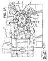
- FIG. 9Ais a top plan view of the transfer turret assembly
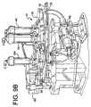
- FIG. 9Bis a top plan view of the transfer turret assembly with the heaters removed;
- FIG. 10is an elevation view of the folding wing workstation in a disengaged position
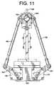
- FIG. 11is an elevation view of the folding wing workstation in an engaged position
- FIG. 12is a motion profile for a folding wing workstation
- FIG. 13is a perspective view of a bottom heating workstation
- FIG. 14is a perspective view of the first bottom forming workstation
- FIG. 15is a perspective view of the second bottom forming workstation
- FIG. 16is a perspective view of the mounting assembly of the second bottom forming workstation of FIG. 15 ;
- FIG. 17is a perspective view of the linear motion assembly of the second bottom forming workstation of FIG. 15 ;
- FIG. 18is a partial exploded view of the second bottom forming workstation of FIG. 15 ;
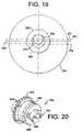
- FIG. 19is an end schematic view of the offsets of the second bottom forming workstation
- FIG. 20is a perspective view of the barrel of the second bottom forming workstation
- FIG. 21is a motion profile for the second bottom forming workstation
- FIG. 22is a perspective view of the tamper and lube workstation
- FIG. 23is a perspective view of one of the curl stations
- FIG. 24is an example of a bottom punch workstation setup screen
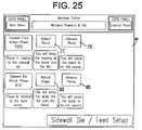
- FIG. 25is an example of a sidewall die/feed setup screen
- FIG. 26is an example of a transfer turret setup screen
- FIG. 27is an example of a folding wing setup screen
- FIG. 28is an example of a bottom heater setup screen
- FIG. 29is an example of a first bottom forming setup screen
- FIG. 30is an example of a second bottom forming setup screen
- FIG. 31is an example of a horizontal rimming turret setup screen
- FIG. 32is an example of a tamper and lube setup screen
- FIG. 33is an example of a pre-curl setup screen.
- FIG. 34is an example of a finish curl setup screen.
- the cup forming machine 10in the present example generally comprises a main or mandrel turret 12 , a transfer turret 14 , and a rimming turret 16 mounted on a frame 18 , however, the cup forming machine may be comprised of a variety of turrets and workstations in a variety of configurations.
- each of the turrets 14 , 16 , 18are horizontal-type turrets.
- a plurality of workstationssurround the mandrel turret 12 , transfer turret 14 and rimming turret 16 .
- some of the workstationsinclude, but are not limited to: a sidewall feeder workstation 20 , a sidewall die cutter workstation 22 , a bottom punch workstation 24 , a folding wing workstation 26 , a first bottom heater workstation 28 , a second bottom heater workstation 30 , a first bottom forming workstation 32 , a second bottom forming workstation 34 , a tamper and lube workstation 36 , a pre-curl workstation 38 , a finish curl workstation 40 , a production discharge workstation 42 and a reject discharge workstation 44 .
- Each of the workstationsis typically mounted to the frame 18 of the cup forming machine 10 .
- each partially formed cup 46generally engages each workstation once.
- one finished cup 90is produced per each cycle of the cup forming machine 10 .
- a single main drive motor connected to a single main drive shaft rotating at a constant angular velocityis utilized to provide the drive for each of the turrets and workstations.
- one drive shaft revolutionconstitutes one machine cycle, during which each workstation performs a particular task on the cup or component thereof associated with a particular mandrel.
- the myriad of mechanical apparatuses and the turrets with which they cooperateare driven by the single main drive shaft. Having a single main drive shaft, however, detrimentally affects the machine performance and capabilities.
- horsepoweris transmitted from the drive shaft at various points along its length by belts, pulleys, chains, gears, cams, etc. which in turn supply power to each of the turrets and workstations.
- the mechanisms of the turrets and workstationsmove, they extract horsepower from the main drive shaft during some portion of each machine cycle.
- various componentsmust be changed and/or re-machined. Additionally, accelerations of mechanisms on the conventional cup forming machine are slower, thereby allowing a lesser amount of dwell time for each mechanism to perform its function.
- a plurality of drive motorsare utilized to drive the different turrets and workstations.
- the drive motorsreceive signals from various controllers and are controlled thereby.
- the drive parameters and profilesmay be independently modified electronically and substantially in real time, and the profiles may be created to allow for increased dwell time of each workstation.
- approximately 18 different servo axes(17 axes with servo motors, 1 ⁇ 2 axis for the encoder for the virtual motor 52 , and 1 ⁇ 2 axis for the digital encoder 296 for the second bottom forming workstation 34
- 22 different motors21 physical motors and 1 virtual electronic motor
- the main controller 49has a memory that stores a plurality of drive or motion profiles, and the main controller 49 is electrically connected to a plurality of drives of various motors and sends signals of the drive profiles to those motors via their respective drives.
- FIG. 8in this embodiment there exists:
- the paper cup forming machine 10creates a finished paper cup 90 such as shown in FIGS. 3–7 .
- This paper cup 90is formed from a sidewall blank 92 wrapped around a bottom blank 94 that is disposed generally transverse thereto.
- the sidewall blank 92is cut or punched from a continuous roll of paper at the sidewall die cutter workstation 22
- the bottom blank 94is cut or punched from a continuous roll of paper at the bottom punch workstation 24 .
- sidewall blanks 92 and bottom blanks 94may be fed by blank feeders into the cup forming machine 10 .
- the sidewall blank 92has a leading edge 91 , adjacent the distal portion 112 of the blank 92 , a trailing edge 93 , which is rolled to form the overturned rim 106 of the cup 90 , a first longitudinal edge 95 and an opposing second longitudinal edge 97 .
- the paper cup 90When formed, the paper cup 90 has a overlapping longitudinal sidewall seam or seal 96 at the joint between the first and second opposing longitudinal edges 95 , 97 , a bottom seal 98 at the joint between the skirt 100 of the bottom blank 94 and the bent lip 102 at the lower region 104 of the sidewall blank 94 , and a curled overturned rim 106 at the upper region 108 of the sidewall 92 leading into the cavity 110 of the cup 90 .
- the longitudinal sidewall seam 96is formed by overlapping one of the first or second longitudinal edges 95 , 97 over the other edge 95 , 97 .
- the bottom seal 98is formed by bending the distal most portion 112 of the sidewall 92 to form the bent lip 102 .
- the bent lip 102is folded over the skirt 100 portion of the bottom blank 94 such that the skirt 100 is squeezed between the distal portion 112 of the sidewall 92 and the bent lip 102 of the sidewall 92 .
- the bottom seal 98is formed of three plies of paper.
- a recessed area 116is created adjacent the side of the bottom blank 94 opposing the cavity 110 of the cup 90 .
- the typical cup 90is made from paperboard blanks having a thermoplastic coating, such as a polyethylene, on at least one side of the blank.
- the thermoplastic materialpermits heating and sealing of adjacent components. It is understood that alternative types of coatings, including environmental friendly coatings, may be utilized with the present invention.
- the sidewall blank 92is a 185 lb. board and has a 0.75 mil. thermoplastic coating on one surface of the blank 92 (i.e., the surface which becomes the inside surface 118 of the formed cup 90 ).
- a thermoplastic coatingmay also be applied to the other surface of the blank 92 in different embodiments.
- the bottom blank 94is made of a 126 lb. board and has a thermoplastic coating on both of it surfaces.
- One surface of the bottom blank 94has a 0.75 mil. thermoplastic coating and the other surface of the bottom blank 94 has a 0.75 mil. thermoplastic coating. Accordingly, in the example of the bottom seal 98 described above, when the sidewall blank 92 is wrapped around the bottom blank 94 , the adjacent heated thermoplastic coated surfaces of the distal portion 112 of the sidewall 92 , the skirt 100 of the bottom blank 94 , and the bent lip 102 of the sidewall blank 92 are pressed together at the second bottom forming workstation 34 to form a strong, leak-proof bottom seal 98 .
- cup forming machine of the present inventioncan manufacture different types of cups as well, including plain paper, waxed paper, etc., and those cups utilizing adhesive seals instead of poly seals. Further, if a thermoplastic coating is utilized, it may be applied to one or both surfaces, and it may be applied in differing thicknesses. The paper types and thicknesses may vary also. Additionally, it is readily understood by one of ordinary skill in the art that the scope of the present invention is not limited to cup forming machines having the identified workstations, and instead the broad aspect of the present invention is applicable to a variety of cup forming machines and configurations thereof.
- the mandrel turret 12is positioned about a vertical axis, and is driven by the main turret drive motor 50 as explained above.
- the mandrel turret 12has a plurality of mandrels 48 extending radially outward from the mandrel turret 12 .
- the mandrels 48are typically frusto-conically shaped, like the cup 90 , and provide a surface on which the cups 90 are formed. If the cup or container 90 that is being formed has a straight wall, however, the mandrel 48 will also have a straight wall.
- the mandrel turret 12has eight equally spaced mandrels 48 , i.e., spaced approximately every 45° about the mandrel turret 12 .
- the main turret motor 50is a servo motor that has a servo drive component to receive command signals from the main controller 49 , and send signals back to the controller 49 and to various drives for other workstations.
- the main turret motor 50is a servo motor.
- servo motorsare electric motors that are designed for high dynamics.
- the servo motoroperates with a servo drive (or amplifier) to control the motor current.
- the servo drivecontrols the current of the motor phases in order to supply the servo motor with exactly the current required for the desired torque and the desired speed.
- the servo motoris equipped with a position sensor, such as an encoder, which provides the servo drive with position and speed feedback.
- a servo driveAs opposed to conventional AC motors which are generally operated at a constant speed (open loop control), a servo drive often operates at highly variable speeds, and often has to accelerate to the rated speed within milliseconds only to decelerate a short time later just as quickly. With servo motors the target position often must be reached exactly with an error of a few millimeters depending on the rating of the motor and drive. To accomplish this function, the servo controller typically has three control loops (torque, velocity, position) that drive the power circuit of the motor by constantly comparing a desired position with actual values to ensure that the motor keeps exactly to the desired motions even under varying load and rapid accelerations and decelerations.
- feedback information for the motoris derived from an encoder attached to the motor shaft of the servo motor.
- the encodergenerates a pulse stream from which the processor can determine the distance traveled, and by calculating the pulse frequency it is possible to measure velocity.
- the drives firmwareis programmed with a mathematical model (also referred to as an algorithm or profile).
- the algorithm or profilepredicts the behavior of the motor in response to a given input command and output position.
- the drive profilealso takes into account additional information like the output velocity, the rate of change of the input and the various tuning settings.
- the main turret motor 50is electrically connected to a plurality of workstations spaced about the periphery of the main turret assembly. Such electrical connection may be direct or indirect.
- the servo drive of the main turret motor 50has three programmable limit switch outputs. These outputs allow the drive of the main turret motor 50 to send out electronic signals when pre-programmed positions are reached by the main turret motor 50 . Accordingly, the main turret motor 50 develops electrical signals of the position of the main motor 50 and sends the electrical signals to the workstations electronically connected thereto to initiate action of the workstations. In a preferred embodiment as shown in FIG.
- the three programmable limit switch output signals of the drive of the main turret motor 50are provided to: (1) the left and right folding wing motors 62 , 64 ; (2) the first and second bottom heater motors 70 , 72 ; and, (3) the first bottom forming motor 74 .
- the main turret motor 50also sends a motion data (positional information) signals 61 directly to the sidewall paper die motor 60 through the sidewall paper die motor's drive.
- the drive of the sidewall paper die motor 60then sends two output signals from its programmable limit switch to (1) the sidewall feeder motor 58 and (2) the transfer turret motor 54 .
- the motion data signal 61is also transferred to the drive of the bottom paper punch motor 68 .
- the bottom paper punch motor 68and in one embodiment more specifically the drive of the bottom paper punch motor 68 , then sends an output signal from its programmable limit switch to the bottom paper feed motor 66 .
- the preferred embodiment of the cup forming machine 10utilizes an electronic virtual motor 52 to mirror the position of the main turret motor 50 in order to provide output signals.
- the electronic virtual motor 52is not a mechanical drive motor, but rather is an electronic computerized motor which operates on an electronic one to one ratio with the main turret drive motor 50 to provide additional programmable limit switch output signals.
- the three programmable limit switch output signals of the virtual motor 52are provided to: (1) the second bottom forming linear motor 78 ; (2) the horizontal rimming turret motor 56 ; and, (3) a gate programmable limit switch 87 .
- the gate programmable limit switch 87provides electronic signals for the controller 49 to create electronic windows to determine when sensor inputs should be evaluated.
- the gate programmable limit switch 87provides electronic windows for receiving signals the bottom paper detect sensor 126 , etc.
- the servo drive of the horizontal turret motor 56which receives its motion trigger signal from the virtual motor 52 that operates on an electronic one to one ration with the main turret drive motor 50 , provides three programmable limit switch output signals to: (1) the tamper lube motor 82 ; (2) the pre-curl motor 84 ; and, (3) the finish curl motor 86 . More specifically, however, the output signals from the programmable limit switch of the drive of the horizontal turret motor 56 are provided to the respective drives of the tamper lube motor, pre-curl motor and finish curl motor. Because a variety of axes and servo motors are utilized to independently control the various workstations, the individual workstations and the motors thereof may be substantially independently operated.
- the main turret motor 50has no specific drive profile. Instead, the main turret motor 50 is commanded by the main controller 49 to rotate at a constant velocity.
- a cam box between the main turret motor 50 and the mandrel turret 12converts the constant rotational velocity of the main turret motor 50 into intermittent motion for the mandrel turret 12 . With the use of the cam box the resultant motion of the mandrel turret 12 is 50% motion index and 50% dwell.
- the bottom punch workstation 24has a bottom paper feed motor 66 and a bottom paper punch motor 68 .
- the bottom paper feed motor 66 and the bottom paper punch motor 68are servo motors.
- the bottom paper feed motor 66receives a signal of a commanded drive or motion profile from the main controller 49 and an electronic signal to begin the drive profile directly from drive of the main turret motor 50 .
- the main controller 49may send both signals to the bottom paper feed motor 66 .
- the bottom paper feed motor 66advances the bottom paper roll at the appropriate velocity and distance such that a required amount of paper is available to be punched to form the bottom blank 94 .
- the bottom punch motor 68is commanded to drive a dual-stage bottom paper punch at a one to one ratio to the main turret 12 . Therefore, like the mandrel turret motor 50 , the bottom punch motor 68 rotates at a constant velocity.
- the dual-stage bottom paper punchoperates to both shear the bottom blank from the roll of paper, and then to form the skirt of the bottom blank.
- one component of the bottom punch workstation 24punches the paper to shear the bottom blank 94 from the continuous roll of bottom wall paper. For one size cup, at this stage the bottom blank 94 is shaped as a disc having approximately a 3′′ diameter.
- a second stage of the bottom punch workstation 24operates to push the disc-shaped bottom blank 94 through the forming ring.
- the forming ringhas approximately a 2.25′′ diameter opening.
- the bottom blank 94is reformed to have a substantially even 0.375′′ skirt portion 100 around the circumference of the bottom blank 94 .
- an air cylinderpushes the formed bottom blank 94 into the opening 120 at the radial end 122 of the adjacent mandrel 48 , and against an outward end wall 124 of the mandrel 48 .
- the edge of the skirt 100which is approximately 0.375′′ long, is adjacent the radial end 122 of the mandrel 48 . It is understood that the specific dimensions for the bottom blank 94 are provided for one exemplar cup shape, and a variety of different shapes, configurations and mechanisms to create the bottom blank 94 are possible without departing from the scope of the present invention.
- the bottom punch workstation 24has its own paper feed motor 66 and bottom paper punch motor 68 , and because the drive profile and parameters for the bottom paper feed motor 66 can be independently modified, the operation and efficiency of this workstation is greatly enhanced. For example, as shown in the bottom punch/feed setup screen 67 in FIG. 24 , the machine operator may retard 69 or advance 71 the phase of the bottom feed motor 66 relative to the bottom punch motor 68 . This allows the operator to either delay the index of the bottom paper into the punch, or to cause the bottom paper to be fed into the punch sooner. Additionally, the bottom feed length can also be adjusted. Further, the drive profile for the bottom paper feed motor 66 stored in the main controller 49 may also be electronically modified.
- the end wall 124 of the mandrel 48has a vacuum which operates to retain the formed bottom blank 94 secure in position.
- the mandrel turret 12is rotated two indexes such that the mandrel 48 with the bottom blank 94 is provided at the folding wing workstation 26 .
- a photo eye 126operates to verify that a bottom blank 94 is provided in the mandrel 48 .
- the sidewall feeder workstation 20 and sidewall die cutter workstation 22are operating to create a sidewall blank 92 for the cup 46 .
- the sidewall feeder motor 58 and sidewall paper die motor 60are servo motors.
- the sidewall paper die motor 60is commanded to drive the sidewall paper die at a one to one ratio to the main turret 12 . Therefore, like the mandrel turret 12 and the bottom punch motor 68 , the sidewall paper die motor 60 generally runs at a constant velocity. Accordingly, in a preferred embodiment, the drive of the sidewall paper die motor 60 is hard wired to the drive of the main turret motor 50 .
- the drive for the sidewall feeder motor 58receives signals from the main controller 49 and the drive of the main turret drive motor 50 (through the drive of the sidewall paper die motor 60 ) such that the feeder motor 58 operates to feed the sidewall blank 94 , and then the sidewall die motor 60 drives the die to cut the sidewall blank 94 .
- a drive or motion profile for the sidewall feeder motor 58resides in the main controller 49 and this drive profile is transmitted to the drive for the sidewall feeder motor 58 from the main controller 49 .
- the drive or motion profile sent to the drive of the sidewall feeder motor 58is initiated based on an initiation signal received from the programmable limit switch of the drive of sidewall paper die motor 60 .
- the sidewall feeder motor 58operates to advance the sidewall paper roll at the appropriate time, position and velocity to the sidewall die cutter workstation 22 .
- the sidewall paper die motor 60operates to reciprocate the sidewall die 130 at the appropriate time, position and velocity (based on its one to one gearing ratio with the main turret) to create the sidewall blanks 92 as described below. For example, as the die 130 gets into the proper position (i.e., as soon as it shears the paper and begins to raise up from the paper) an electronic signal is sent from the drive of the sidewall paper die motor 60 directly to the drive of the sidewall feeder motor 58 to have the sidewall feeder motor 58 begin to feed additional paper to the die 130 .
- the sidewall die cutter workstation 22employs a progressive reciprocating die 130 that is driven by the sidewall paper die motor 60 .
- the term progressive in reference to the sidewall diemeans that the trailing edge of one sidewall blank 92 and the leading edge of the following sidewall blank 92 are die cut at the same time.
- the die 130is reciprocating in that the die moves in an alternating up and down motion to cut the paper that becomes the sidewall blank 92 .
- the rotary motion of the sidewall paper die motor 60is converted into reciprocating motion for the die cutter 22 .
- the shape of the die 130 for the sidewall die cutter workstation 22is substantially U-shaped to conform with the shape of the sidewall blank 92 (see FIG. 4 ). More specifically, for each sidewall blank 92 the die 130 cuts the trailing edge 93 and the two longitudinal edges 95 , 97 . Additionally, during the same stroke the die 130 also cuts the leading edge 91 of the next sidewall blank 92 .
- the sidewall feeder workstation 20 and sidewall die cutter workstationeach have their own motors identified above, and the drive profile and operating parameters for the sidewall feeder motor 58 can be independently modified.
- the operating parametersmay be quantitatively modified at an input station electrically connected to the main controller 49 .
- the machine operatormay retard 77 or advance 79 the phase of the sidewall feeder motor 58 relative to the sidewall paper die motor 60 . This allows the operator to either delay the feeding of the sidewall blank paper into the die, or to cause the sidewall blank paper to be fed into the die sooner.
- the machine operatormay retard 83 or advance 85 the phase of the sidewall die motor 60 relative to the main turret motor 50 . This allows the operator to either delay when the die cuts the blank 92 , or to cause the blank 92 to be cut sooner. Further, since the drive profile for the sidewall feeder motor 58 is stored in the main controller 49 and can be electronically modified.
- a pair of fingers 128 on the transfer turret 14grasps the sidewall blank 92 at the leading edge 91 thereof.
- the fingers 128are operated (i.e., opened and closed) by a cam follower that is manipulated by a cam driven by the sidewall die motor 60 , which operates on a one to one drive ratio with the main turret 12 .
- the fingers 128are opened and closed to fixedly accept the sidewall blank 92
- the fingers 128are opened to release the sidewall blank 92 to the folding wing workstation 26 .
- the fingers 128provide to ensure that the roll of paper is positively held and the position is accurately known both prior to cutting the paper and after the blank 92 is cut.
- the transfer turret 14has five stations on the transfer turret 14 , each station spaced approximately 72°. Each of the stations has a set of fingers 128 which can be adjusted to selectively retain and release a sidewall blank 92 .
- the die 130 of the sidewall die cutter workstation 22performs the task of cutting the three remaining sides of the sidewall blank 92 .
- the transfer turret motor 54is a servo motor. As explained above and shown in FIG. 8 , the drive of the transfer turret motor 54 receives a drive or motion profile signal from the main controller 49 and another signal, a command signal, to begin the drive profile via the programmable limit switch output from the drive of the sidewall paper die motor 60 . Because the transfer turret 14 has its own motor 54 , and because the drive profile and parameters for this motor 54 can be independently modified, the operation and efficiency of this turret is greatly enhanced. For example, as shown in the transfer turret setup screen 103 in FIG.
- the machine operatormay retard 105 or advance 107 the phase of the transfer turret motor 54 relative to the main turret motor 50 . This allows the operator to either delay the index of the transfer turret, or to cause the transfer turret to index sooner. Also, the drive or motion profile for the transfer turret motor 54 that is stored in the main controller 49 may also be electronically modified.
- the transfer turret 14is rotationally advanced by the transfer turret motor 54 to subsequent radial locations to heat the polyethylene coating on the sidewall blank 92 for forming the longitudinal sidewall seam 96 at the folding wing workstation 26 , and to pre-heat the lower region 104 of the sidewall blank 92 for forming the bottom seal 98 at the second bottom forming workstation 34 .
- heat in the form of hot airis blown on the lower region 104 of the inner surface 118 of the sidewall blank 92 adjacent the leading edge 91 thereof.
- the first heating location 132has one heater 134 .
- the transfer turret 14is then rotationally advanced to move the sidewall blank 92 to the second heating location 136 .
- the second heating location 136has 3 heaters.
- the first heater 138 at the second heating location 136is utilized to provide heat, in the form of hot air, to the longitudinal edges 95 , 97 of the inner surface 118 of the sidewall blank 92 ;
- the second heater 140 at the second heating location 136is utilized to provide heat, in the form of hot air, to the lower region 104 of the inner surface 118 of the sidewall blank 92 adjacent the leading edge 91 thereof;
- the third heater 142is utilized to provide heat, in the form of hot air, to the longitudinal edges 95 , 97 , but at the outer surface of the sidewall blank 92 .
- each of the heaters 134 , 138 , 140 , 142comprise a stainless steel cylinder housing an electric cartridge heater. The heater is energized and air is blown past the heater to heat the air. The heated air is then expelled from the heater at a manifold to diffuse the heated air on the appropriate locations on the sidewall blank 92 . It is understood that additional means for heating the polyethylene coating are possible, such as electric or gas radiant heat.
- the transfer turret 14is rotationally advanced to move the sidewall blank 92 to the folding wing workstation 26 .
- the sidewall blank 92is transferred from the transfer turret 14 to the main or mandrel turret 12 .
- another mandrel 48 with a bottom blank 94is provided at the folding wing workstation 26 and adapted to receive a sidewall blank 92 .
- the folding wing workstation 26comprises a mounting bracket 143 , a left folding wing motor 62 , a right folding wing motor 64 , a left crank arm 144 , a left connector 146 , a left folding wing 148 , a right crank arm 150 , a right connector 152 , a right folding wing 154 and a foot clamp 156 .
- the left crank arm 144is connected to the left folding wing motor 62
- the left connector 146is connected at one end to the left crank arm 144 and at the other end to the left folding wing 148 .
- the right crank arm 150is connected to the right folding wing motor 64
- the right connector 152is connected at one end to the right crank arm 150 and at the other end to the right folding wing 154 .
- the left and right folding wing motors 62 , 64are mounted to the mounting bracket 143
- the left and right folding wings 148 , 154are pivotally connected to a common pivot member of the mounting bracket 143 . Accordingly, both the left and right folding wings 148 , 154 pivot about the same point.
- the folding wing workstation 26generally operates to wrap the sidewall blank 92 around the mandrel 48 and form the frustoconically shaped sidewall of the formed cup 90 .
- the left and right folding wing motors 62 , 64are servo motors.
- Each of the respective drives of the folding wing motors 62 , 64receive a drive profile signal, which as with all the drive profile signals contains the appropriate drive profile for the drive of the servo motor, from the main controller 49 .
- each of the drives of the folding wing motors 62 , 64receives a signal directly or indirectly from the drive of the main turret drive motor 50 to begin their respective drive profiles.
- the sidewall blank 92is located directly under the mandrel 48 .
- the folding wings 148 , 154are in a lowered position to allow the transfer turret 14 to advance the sidewall blank 92 into position, and to allow the mandrel turret 14 to advance into the aligned position with the folding wing workstation 26 .
- the foot clamp 156 of the folding wing workstation 26is raised to positively clamp the sidewall blank 92 to the bottom of the mandrel 48 .
- the fingers 128 of the transfer turret 14are lifted to release the sidewall blank 92 from the transfer turret 14 , and the folding wings 148 , 154 , are raised to fold the sidewall blank 92 around the mandrel 48 .
- the raising of the foot clamp 156 to engage the sidewall blank 92 and the releasing of the sidewall blank 92 by the fingers 128is initiated by cam action driven by the main turret 12 .
- Each of the folding wings 148 , 154are manipulated by separate folding wing motors 62 , 64 . Accordingly, as the left folding wing motor 62 is driven the left crank arm 144 is rotated. When the left crank arm rotates 144 the left connector 146 moves up and down.
- the left connector 146is rotatably connected to the left folding wing 148 that is pivotally connected to the mounting bracket 143 , when the left connector 146 moves up and down the left folding wing 148 is manipulated to wrap the left folding wing 148 , and the side of the sidewall blank 92 positioned thereover about the mandrel 48 .
- the same operationoccurs with the right folding wing 154 and the other side of the sidewall blank 92 . This is referred to as the engaged position of the folding wing workstation 26 , and is shown in FIG. 11 .
- the longitudinal sidewall seam 96is created by an overlapping joint between the first and second opposing longitudinal edges 95 , 97 of the sidewall blank 92 .
- one of the folding wingsmust complete its folding of the sidewall blank 92 around the mandrel 48 prior to the opposing side of the sidewall blank 92 .
- both folding wings 148 , 154start their movement at the same time, however, one of the folding wings (typically the left folding wing 148 ) is commanded to complete its motion in slightly less time than the right folding wing 154 .
- a seal clamp 158 from the mandrel turret 12clamps down on the seam 96 to sealingly join the opposing longitudinal edges 95 , 97 of the sidewall blank 92 .
- the seal clamp 158is a component of the mandrel turret 12 and rotates with the mandrel turret 12 .
- the seal clamp 158maintains a clamping pressure on the sidewall 92 of the cup until the seal clamp 158 is released, explained later herein, when the mandrel 48 of the main turret 12 is associated with a mating cup receiver 300 of the horizontal pocket or rimming turret 16 .
- the longitudinal seal 96is created by the adherence of the heated polyethylene on the interior surface 118 of the outer overlapping edge 95 or 97 of the sidewall blank 92 against the outer surface of the opposing inner overlapping edge 95 or 97 of the sidewall blank 92 .
- the foot clamp 156releases the bottom of the sidewall blank 92 and the folding wings 148 , 154 are rotated away from the mandrel 48 and back to the lowered or disengaged position as shown in FIG. 10 .
- this embodiment of the folding wing workstation 26 for the cup forming machine 10has separate motors 62 , 64 for each of the left and right folding wings 148 , 154 , both of which are separately controllable, the cup machine 10 can control which folding wing 148 , 154 finishes the folding of the sidewall blank 92 prior to the other folding wing 148 , 154 .
- the ability to control this featureelectronically allows the cup forming machine 10 to create cups 90 with either a left-over-right longitudinal seal 96 or a right-over-left longitudinal seal 96 .
- the motion profilei.e., the timing, distance, velocity
- each of the folding wings 148 , 154can be independently controlled and manipulated merely by adjusting the drive parameters and/or drive profile.
- FIG. 12An example of one motion profile for the folding wing workstation 26 is shown in FIG. 12 .
- the left and right folding wings 148 , 154begin to fold the sidewall blank 92 at approximately the same time, but the left wing 148 finishes folding its side of the sidewall blank 92 prior to the right wing 154 to create the overlap for the longitudinal seal 96 .
- the folding wing workstation 14has its own motors 62 , 64 , and because the drive profile and parameters for these motors 62 , 64 can be independently modified, the operation and efficiency of this workstation is greatly enhanced.
- the machine operatormay manipulate the stop position 147 of the left folding wing, as well as the stop position 149 of the right folding wing. This allows you to adjust the tightness of the wrap based on various thicknesses of paper being run.
- the main turret 12is advanced to the next workstation for further processing of the partially formed cup 46 .
- the next workstationis the first bottom heater workstation 28 , which is shown in FIG. 13 .
- the first bottom heater workstation 28operates to heat the polyethylene on the inside surface 118 of the distal end portion 112 of the sidewall blank 92 .
- the heater 160 for the first bottom heater workstation 28comprises a stainless steel cylinder housing an electric cartridge heater. The heater is energized and air is blown past the heater to heat the air. The heated air is then expelled from the heater at a manifold to diffuse the heated air on the appropriate locations on the sidewall blank 92 .
- the first bottom heater workstation 28generally comprises a mounting fixture 162 , a first heater motor 70 , a heater 160 , a heater tool/diffuser 166 , and a drive fork and cam assembly to convert the rotational motion of the first heater motor 70 to linear motion of the heater tool 166 .
- the first heater motor 70is a servo motor.
- a drive of the first heater motor 70receives a signal from at least one of the main controller 49 and a controller for the main turret motor 50 , and in response to that signal the first heater motor 70 moves the heater tool 166 into and out of the recessed area 116 of the bottom of the cup 90 according to a specific drive profile.
- the drive profile for the first heater motor 70resides in the main controller 49 .
- the drive profileis transmitted to the drive of the first heater motor 70 from the main controller 49 .
- the drive of the first heater motor 70receives an electronic command signal to begin its motions.
- the main motor 50cycles its drive sends out signals to the various components at different positions of its cycle.
- the drive of the main turret motor 50sends out a signal to the drive of the first heater motor 70 to have that motor initiate its programmed drive profile.
- the end of the heater tool 166is cylindrically shaped and has a plurality of apertures 168 about its circumference. Heated air is forced into a central cavity of the heater tool 166 and is then forced out of the apertures 168 to heat the polyethylene on the inside surface 118 of the sidewall blank 92 . More specifically, in a preferred embodiment for one size cup 90 , when the sidewall blank 92 is wrapped around the mandrel 48 the distal end portion 112 of the sidewall blank 92 extends approximately 0.750′′ past the end 122 of the mandrel 48 and this portion of the sidewall blank 92 is heated.
- the profile for the first heater motor 70is designed such that heater tool/diffuser 166 is inserted into the recessed area 116 immediately as the mandrel 48 is properly positioned. Further, because the first bottom heater workstation 28 has its own drive motor 70 , and because the drive profile for the first heater motor 70 can be independently modified, the heater tool 166 can be inserted and removed from the recessed area 116 at a faster rate, thereby allowing more dwell time for the heater tool 166 to provide increased heat to the sidewall blank 92 for an excellent bottom seal. Providing increased dwell time for each workstation of the cup forming machine 10 is one feature of the present invention.
- the dwell for substantially each of the workstations of the cup forming machine 10may be adjusted at the input station 51 and set independent of the machine speed of the cup forming machine 10 . Additionally, it is understood that the input station 51 is electrically connected to the main controller 49 , and, various parameters for the motors can be quantitatively controlled and adjusted at the input station 51 of the main controller 49 .
- FIG. 28An example of a bottom heater setup screen 161 is shown in FIG. 28 .
- the machine operatormay retard 163 or advance 165 the phase of the bottom heater motor 70 relative to the main turret motor 50 to either delay the heater tool/diffuser 166 from moving into the recessed area 116 or cause the heater tool 166 to move into the recessed area 116 more quickly.
- the setup screen 161allows the operator to adjust the retracted position 167 and extended position 169 of the heater tool 166 , as well as to adjust the dwell time 171 (i.e., the time the heater tool 166 remains inside the recessed area 116 to heat the cup).
- the drive profile for the first heater motor 70 that is stored in the main controller 49may also be electronically modified.
- the main turret 12advances the mandrel 48 and partially formed cup 46 to the second bottom heater workstation 30 .
- the end wall 124 of the mandrel 48is advanced radially outward 0.375′′.
- the edge of the skirt portion 100 of the bottom blank 94is positioned 0.375′′ outside the mandrel 48 opening, and is adjacent the inside surface 118 of the distal end portion 112 of the sidewall blank 92 .
- the polyethylene of the surface of the skirt 100 facing the recessed area 116is heated.
- the second bottom heater workstation 30has a similar components and operation to the first bottom heater workstation 28 , and as such reference to FIG.
- the drive of the second heater motor 72receives a signal from at least one of the main controller 49 and a drive for the main turret motor 50 , and in response to the one or more signals the second heater motor 72 moves the heater tool 166 into and out of the recessed area 116 of the bottom of the cup 90 according to a specific drive profile.
- the drive for the second heater motor 72receives a command drive profile from the main controller 49 .
- the drive of the main turret motor 50sends an electronic signal from its programmable logic switch as a pre-programmed position is reached to the drive for the second heater motor 72 to have the drive profile initiated at the second heater motor 72 .
- the second bottom heater workstation 30has its own drive motor 72 and drive profile therefore to allow for nearly complete control and manipulation of the second bottom heater workstation 30 .
- the first bottom forming workstation 32generally comprises a workstation that bends a portion of the distal end portion 112 of the sidewall blank 92 over the skirt 100 of the bottom blank 94 to prepare the cup for sealing of the sidewall blank 92 to the bottom blank 94 to form the bottom seal 98 of the cup 90 .
- the first bottom forming workstation 32generally comprises a mounting fixture 170 , a first bottom forming linear motor 74 , a reformer tool 172 , a drive fork 174 to assist in converting the rotational motion of the first bottom forming motor 74 to linear motion for the reformer tool 172 , a constant rotation motor 75 to rotate the reforming tool 172 , and a slide mechanism 178 to allow the reforming tool 172 to move inward and outward.
- the constant rotation motor 75is a conventional AC motor that continually rotates the reformer tool 172 at a constant rate of revolution.
- the constant rotation motor 75is connected to the reforming tool 172 via a ball/spline mechanism, and the reforming tool 172 is connected to the slide mechanism 178 .
- the constant rotation motor 75may be fixed to the slide mechanism 178 .
- the ball/spline mechanismallows the reforming tool 172 to move in and out while still being rotated by the constant rotation motor 75 .
- the first bottom forming motor 74provides the drive to move the slide mechanism 178 , including the rotating reforming tool 172 , inward and outward. More specifically, the drive fork 174 that is connected to the drive shaft driven by the bottom forming motor 74 manipulates a cam follower extending from the slide mechanism 178 .
- the first bottom forming motor 74is a servo motor.
- the drive of the first bottom forming motor 74receives a drive or motion profile in the form of a drive profile signal from the main controller 49 , and an electronic signal to trigger the motion from the main turret motor 50 .
- the first bottom forming motor 74initiates its drive profile and moves the slide mechanism 178 having the reforming tool 172 inward to engage the sidewall 92 of the partially formed cup 46 .
- the drive or motion profile for the first bottom forming motor 74resides in the main controller 49 . The drive profile is transmitted to the drive of the first bottom forming motor 74 from the main controller 49 .
- the drive of the first bottom forming motor 74receives a hard-wired signal from the drive of the main turret motor 50 , and more specifically from the programmable limit switch of the drive of the main turret motor 50 . As the main motor 50 cycles its drive sends out signals to the various components at different positions of its cycle.
- the drive of the main motor 50sends out a signal to the drive of the first bottom forming motor 74 to have that motor initiate its programmed drive or motion profile, which generally moves the reforming tool 172 inward toward the mandrel 48 at a rapid velocity and for a specific distance to engage the sidewall 92 , then it slows to a lower speed as it completes approximately the last 0.375′′ of movement (which provides to curl or bend the paper), and then dwells for a period of time to eliminate the jerk effect of reversing motions. Finally, the first bottom forming motor 74 reverses backward at a rapid velocity to disengage the sidewall 92 .
- the function of the first bottom forming workstation 32is to bend the distal end portion 112 of the sidewall blank 92 radially inwardly to create the bent lip 102 of the sidewall blank 92 .
- the bent lip 102 of the sidewall blank 92is positioned over the skirt 100 of the bottom blank 94 , as shown in FIG. 7 , such that the second bottom forming workstation 34 can seal the distal end portion 112 of the sidewall blank 92 to the skirt 100 of the bottom blank 94 to form the bottom seal 98 , as shown in FIG. 6 .
- FIG. 29An example of a first bottom forming setup screen 175 is shown in FIG. 29 .
- the machine operatormay adjust the extended position 179 of the reforming tool 172 , which automatically adjusts the retracted position 177 based on an internal calculation by the main controller 49 .
- the mandrel turret 12is advanced to the second bottom forming workstation 34 (See FIG. 1 ).
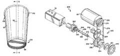
- the second bottom forming workstation 34is shown separately in FIGS. 15–21 .
- the second bottom forming workstation 34generally irons or seals the distal end portion 112 of the sidewall blank 92 around the skirt 100 of the bottom blank 94 to form the bottom seal 98 of the cup 90 (see FIGS. 6 and 7 ).
- a bottom seal tool 210 having a patterned circumferenceapplies a substantially uniform pressure over the entire circumference of the distal end portion 112 of the cup after the bent lip 102 of the sidewall blank 92 is positioned over the skirt 100 of the bottom blank 94 .
- This functionis complicated by the fact that a typical cup 90 is formed at an approximate 5° taper angle to the central longitudinal axis of the cup 90 . Thus, engaging the bottom seal tool 210 to the cup 90 is made more difficult.
- the bottom seal tool 210To perform this function the bottom seal tool 210 must first be moved linearly into the recessed area 116 at the bottom of the cup 90 , and then moved laterally or radially outward toward the bent lip 102 over the skirt 100 to engage these components for applying the pressure necessary to create the bottom seal 98 .
- one embodiment of the present inventionutilizes offset bores in a rotating barrel and an eccentric shaft, in combination with a phase adjustment motor 76 , to change the center of rotation of the bottom seal tool 210 relative to the center of the cup 90 .
- the second bottom forming workstation 34generally comprises a linear motion assembly 200 to assist the bottom sealing tool 210 in moving linearly into and out of the recessed area 116 of the cup 90 , a constant rotation assembly 202 to move the bottom seal tool 210 in a circle, a phase change assembly 204 to adjust the radius of the circle in which the bottom seal tool 210 moves (i.e., to move the bottom seal tool 210 outward to engage the bent lip 102 and skirt 100 and then back inward after the bottom seal 98 is created), and a tracking assembly 206 for monitoring the rotation of the various components of the phase change assembly 204 , each of which are mounted to a mounting assembly 208 .
- These assemblies of the second bottom forming workstation 34work together to manipulate the bottom seal tool 210 such that it seals the skirt 100 to the distal end portion 112 and bent lip portion 102 of the sidewall blank 92 to create the bottom seal 98 for the cup 90 as shown in FIG. 6 .
- FIG. 16One example of the mounting assembly 208 of the second bottom forming workstation 34 is shown in FIG. 16 , and includes a mounting plate 212 , a two opposing risers 214 , a main plate 216 , a first support bracket 218 for supporting the second bottom forming lateral motor 78 , a second opposing support bracket 220 , a first motor mount plate 222 for supporting the second bottom forming rotary motor 80 , and a second motor mount plate 224 for supporting the second bottom forming phase adjustment motor 76 .
- the mounting plate 212 and the main plate 216are located in substantially parallel spaced relation, and the two risers 214 are secured between the mounting plate 212 and the main plate 216 to maintain the spaced relation therebetween.
- the risers 214operate to raise the main plate 216 up from the machine table.
- the first support bracket 218extends transverse, and substantially perpendicular to the main plate 216 and the mounting plate 212 , and the first support bracket 218 is secured at its bottom end to one of the risers 214 .
- the second support bracket 220also extends transverse and substantially perpendicular to the main plate 216 and the mounting plate 212 in an opposing spaced relation to the first support bracket 218 .
- the second support bracket 220is secured at its bottom end to the other of the risers 214 .
- the first motor mount plate 222is positioned at the front and toward a top of the first and second support brackets 218 , 220 , and is further fixedly connected to the first and second support brackets 218 , 220 .
- the first motor mount plate 222When assembled, the first motor mount plate 222 is located in a plane substantially parallel to a plane at the front face of the bottom seal forming tool 210 .
- the second bottom forming rotary motor 80is connected to a rear face 223 of the first motor mount plate 222 , and the drive shaft 274 of the second bottom forming rotary motor 80 extends through an aperture in the first motor mount plate 222 for driving the constant rotation assembly 202 as explained below.
- the first motor mount plate 222also aids in adding rigidity to the first and second support brackets 218 , 220 , and to the overall mounting assembly 208 .
- the second motor mount plate 224is provided at a generally rear portion of the mounting assembly 208 to support the second bottom forming phase adjustment motor 76 .
- the second motor mount plate 224is located in substantially parallel spaced relation to the first motor mount plate 222 , and as such is extends transversely upward from the main plate 216 and substantially perpendicular to the first and second support brackets 218 , 220 .
- the linear motion assembly 200 of one embodiment of the second bottom forming workstation 34is shown in FIG. 17 , and in a preferred embodiment generally includes a motor (the second bottom forming linear motor 78 ), a right angle gear box 226 , a drive fork 228 and a slide assembly 230 .
- the linear motion assembly 200is at least partially moveably connected to the mounting assembly 208 .
- the right angle gear box 226 and motor 78are connected to the first support bracket 218 .
- a drive shaft 232 extending from the gear box 226extends through an aperture in the first support bracket 218 , and the drive fork 228 is connected to the portion of the gear box drive shaft 232 extending through the first support bracket 218 .
- a cam follower 234extends from the slide assembly 230 and is positioned between fork arms of the drive fork 228 to laterally move the slide assembly 230 in response to rotation of the second bottom forming linear motor 78 .
- the second bottom forming linear motor 78is a servo motor.
- the slide assembly 230slides back and forth (i.e., toward and away from the mandrel 48 on the main turret 12 ) on a pair of slide rails 236 that are mounted to the main plate 216 in response to the rotation of the second bottom forming linear motor 78 .
- the cam follower 234which is connected to one of the side plates 238 of the slide assembly 230 , is manipulated by the drive fork 228 and moves the slide assembly 230 back and forth on the slide rails 236 .
- the slide assembly 230generally comprises a drive plate 240 at the bottom of the slide assembly 230 , two opposing side plates 238 extending upward from the drive plate 240 , a front plate 242 onto which the forming collar 244 is connected, a front bearing plate 246 connected between the side plates 238 , and a rear bearing plate 248 connected between the side plates 238 .
- the front plate 242has an aperture therein concentric with the opening 243 of the forming collar 244 to allow the forming tool 210 to reside and move within the opening 243 of the forming collar 244 .
- Bearings 250extend from the side plates 238 to engage the slide rails 236 and to positively secure the slide assembly 230 in sliding engagement with the slide rails 236 .
- front and rear bearing plates 246 , 248house bearings to support a portion of the rotating barrel 254 between the front and rear bearing plates 246 , 248 .
- a rotatable tool shaft 256is rotatably contained within an offset bore 258 in the barrel 254 .
- the tool shaft 256 and barrel 254move inward and outward with the slide assembly 230 .
- the rotatable tool shaft 256is also a component of the phase change assembly 204 .
- the phase change assembly 204generally comprises the second bottom forming phase adjustment motor 76 , an external ring gear 260 driven by the second bottom forming phase adjustment motor 76 , and an internal planetary gear 262 connected to the tool shaft.
- the phase change assembly 204is operably connected to the tool shaft 256 .
- the tool shaft 256has a first end 264 at which the internal gear 262 is connected thereto.
- the shaft 256also has central portion 266 that is housed in bearings 268 in the offset bore 258 in the barrel 254 .
- the shaft 256has an eccentric stub shaft portion 270 that extends from a second end 272 of the shaft 256 .
- the bottom seal finishing tool 210is connected to the eccentric stub shaft 270 at the second end 272 of the shaft 256 .
- the shaft 256has a centerline or central longitudinal axis 257 .
- the eccentric stub shaft portion 270has a centerline or central longitudinal axis 271 that is offset from the central longitudinal axis 257 of the shaft.
- the central longitudinal axis 271 of the eccentric stub shaft 270is offset 0.125′′ from the central longitudinal axis 257 of the shaft 256 .
- the constant rotation assembly 202 of the second bottom forming workstation 34is best shown in FIGS. 15 and 18 .
- the constant rotation assembly 202includes a constant rotation motor 80 (i.e., the second bottom forming rotary motor 80 ) which drives the barrel 254 .
- the constant rotation motor 80is an A.C. motor that continually rotates the barrel 254 at a constant rate of revolution, such as 1,725 revolutions per minute in one embodiment.
- the constant rotation motor 80is mounted to the rear face 223 of the first motor mount plate 222 , and the drive shaft 274 of the constant rotation motor 80 extends through an aperture in the first motor mount plate 222 .
- a sheave 276is connected to the drive shaft 274 of the constant rotation motor 80 , and a V-belt 278 is provided between the sheave 276 and the barrel 254 to drive the barrel 254 .
- the barrel 254has a V-groove 280 in the circumference thereof to accept the V-belt 278 .
- the barrel 254is associated with each of the linear motion assembly 200 , the constant rotation assembly 202 and the phase change assembly 204 (as well as the tracking assembly 206 as described below), however one of ordinary skill in the art would understand that a single component, such as the barrel 254 , need not be associated with each of these assemblies, and instead multiple components may be utilized to perform the same functions as the barrel 254 . Notwithstanding, in a preferred embodiment, as shown in FIGS. 19 and 20 , the barrel 254 comprises a substantially cylindrical component having a first hub 282 extending from one end of the barrel 254 , and a concentric second hub 284 extending from the opposing end of the barrel 254 .
- the barrelis cylindrical, it is understood that it could be any shape and is not limited to this configuration.
- the first hub 282is positioned within the bearing in the front bearing plate 246
- the second hub 284is positioned within the bearing in the rear bearing plate 248 .
- the barrel 254is free to rotate within the slide assembly 230 of the linear motion assembly 200 of the second bottom forming workstation 34 , and on the same longitudinal axis as the mandrel 48 .
- the barrel 254has a central axis 255 extending from the first end 286 of the barrel 254 to the second end 288 of the barrel 254 .
- the barrel 254rotates about its central axis 255 (on the first and second hubs 282 , 284 ).
- the barrel 254further has an offset bore 258 extending from the first end 286 to the second end 288 of the barrel 254 .
- the central axis 290 of the offset bore 258is not concentric with the central axis 255 of the barrel 254 , and rather is offset from or eccentric to the central axis 255 of the barrel 254 .
- the central axis 290 of the offset bore 258is offset 0.250′′ radially outward from the central axis 255 of the barrel 254 . Accordingly, as the barrel 254 is rotated by the constant rotation motor 80 , the shaft 256 in the barrel bore 258 will move in a circle about a 0.250′′ radius to the center of the central axis 255 of the barrel 254 due to its being seated in the bore 258 offset from the central axis 255 of the barrel 254 .
- the shaft 256has a central portion 266 that is housed within the bearings 268 in the offset bore 258 of the barrel 254 , and an eccentric stub shaft portion 270 that extends outside the first end 286 of the barrel 254 .
- the central longitudinal axis 271 of the eccentric stub shaft 270(on which the bottom seal finishing tool 210 is connected) is offset 0.125′′ from the central longitudinal axis 257 of the shaft 256 . Accordingly, the offset relationship between the central axis 255 of the barrel 254 (i.e., the center of rotation of the barrel 254 ) and the central axis 271 of the bottom seal finishing tool 210 can be modified between 0.125′′ and 0.375′′.
- the finishing tool 210can revolve about the center of the barrel 254 on a radius that can be modified between 0.125′′ and 0.375′′ in addition to the radius of the offset bore to the center of the barrel.
- the finishing tool 210can be made to apply pressure to iron the skirt 100 to the distal end portion 112 and bent lip portion 102 of the sidewall blank 92 to create the bottom seal 98 for the cup.
- the amount of pressure applied by the finishing tool 210 on the cup 90can be made to change or be varied. Accordingly, different types of seals and different pressures can be applied by merely modifying the phase relationship to increase or decrease the amount of offset through the rotation of the tool shaft 256 . Further, tool wear can accommodated for electronically instead of having to re-machine or replace various components.
- phase relationship between the barrel 254 and the tool shaft 256is controlled by the relationship of the velocity of the constant rotation motor 80 that rotates the barrel 254 , and the velocity of the second bottom forming phase adjustment motor 76 that rotates the external ring gear 260 . If the velocities match the phase remains the same and the relative position of the two remains the same. If the velocities do not match, the phase will continue to change at a rate equal to the difference in velocity. As the constant rotation motor 80 rotates the barrel 254 , the shaft 256 moves in a circle due to the shaft 256 being seated in the offset bore 258 of the barrel 254 .
- the velocity of the constant rotation motor 80is constant at approximately 1,725 revolutions per minute.
- the velocity of the barrel 254is also approximately constant, and is monitored by the tracking assembly 206 described below.
- the tracking assembly 206tracks the velocity of the barrel 254 and provides position and velocity reference back to the drive for the second bottom forming phase adjustment motor 76 . This information allows the second bottom forming phase adjustment motor 76 , which controls the rotation of the tool shaft 256 , to move in synchronization with the barrel 254 (i.e., at the same velocity).
- the second bottom forming phase adjustment motor 76advances the phase relationship between the tool shaft 256 and the barrel 254 by increasing the velocity of the external ring gear 260 which spins the internal planetary gear 262 to spin the shaft 256 .
- the eccentric stub shaft 270 portion of the tool shaft 256is rotated.
- the tool 210is rotated outward by adjusting the relationship of the radius of rotation of the tool 210 to the barrel 254 through spinning the tool shaft 256 having the eccentric stub shaft 270 portion.
- the second bottom forming phase adjustment motor 76is a servo motor. Further, in a most preferred embodiment the servo motor of the second bottom forming phase adjustment motor 76 has a drive that is electrically connected to the drive (i.e., a programmable limit switch output) of the virtual motor 52 .
- the second bottom forming phase adjustment motor 76ramps back down to a one to one velocity ratio with the barrel to maintain the same phase relationship between the forming tool 210 and the barrel 254 .
- the tool 210rotates in a radius such that the tool 210 , which has been moved radially outward to engage the cup 90 , rotates around the entire inner circumference of the cup to rotatedly iron the skirt 100 to the distal end portion 112 and bent lip portion 102 of the sidewall blank 92 to create the bottom seal 98 for the cup.
- the second bottom forming phase adjustment motor 76retards the phase relationship between the tool shaft 256 and the barrel 254 (i.e., it decreases the velocity of the external ring gear for a period of time and then returns to the same velocity to spin the tool shaft 256 to move its eccentric stub portion 270 back to its original radial position), thereby returning the forming tool 210 back to its original smaller-radius circle of rotation which is disengaged from the cup 90 so that the forming tool 210 can be removed from the recessed area 116 of the cup 90 (see FIG. 21 ).
- the second bottom forming phase adjustment motor 76returns to a one to one velocity ratio with the barrel 254 and the second bottom forming linear motor 78 retracts the slide assembly 230 to remove the tool 210 from the cup 90 and to allow the main turret 12 to advance the mandrel 48 to the next workstation.
- the tracking assembly 206which is best shown in FIGS. 15 and 18 , assists in providing a signal of the velocity and position of the barrel 254 .
- the components for providing the signal for the tracking assembly 206comprise a first gear 292 connected to the outside of the barrel 254 , a mating second gear 294 geared at a one to one ratio with the first gear 292 , and an encoder 296 driven by the mating second gear 294 . Since the encoder 296 is geared at a one to one ratio with the barrel 254 , the encoder 296 can track the speed of the barrel 254 to provide position and velocity reference data of the barrel 254 to the drive of the second bottom forming phase adjustment motor 76 . This information is provided to the second bottom forming phase adjustment motor 76 to control the rotation of the shaft 256 and to keep the phase relation of the shaft 256 synchronized with the barrel 254 according to the drive profile.
- the second bottom forming workstation 34operates through a series of interconnected assemblies. At some point immediately prior to or during the advancement of a mandrel 48 by the main turret 12 from the first bottom forming workstation 30 to the second bottom forming workstation 34 , a signal is sent from the drive of the main turret motor 50 (via the virtual motor drive 52 ) to the second bottom forming workstation 34 to initiate linear movement.
- the actions that the motors of the second bottom forming workstation 34 are to initiateare based on drive or motion profiles stored in the main controller 49 and transferred to the respective drives of the second bottom forming linear motor 78 and second bottom forming phase adjustment motor 76 . Additionally, it is understood that the main controller 49 controls power to the second bottom forming rotary motor 80 (the constant rotation motor for the second bottom forming workstation 34 ) to maintain that motor rotating the barrel 254 at a constant rate of revolution.
- the first action by the second bottom forming workstation 34is to have the drive profile for the second bottom forming linear motor 78 initiated.
- the second bottom forming linear motor 78is energized and rotates the drive fork 228 , which in turn engages the cam follower 234 to slide the slide assembly 230 toward the mandrel 48 having the partially formed cup thereon.
- a portion of the slide assembly 230is positioned around the distal portion of the sidewall 112 , the skirt 100 and the bent lip portion of the sidewall 102 of the partially formed cup.
- the forming collar 244is positioned about the periphery of the identified lower portion of the partially formed cup 46 such that the cup is positioned within the opening 243 in the forming collar 244 . Further, as the slide assembly 230 is moved into its appropriate position the forming tool 210 , which is rotating in a circle in a portion of the opening 243 in the forming collar 244 based on the rotation of the barrel 254 from the constant rotation assembly 202 , will be located within the recessed area 116 of the cup 90 and still rotating in the same circle. Thus, the distal end portion 112 of the sidewall blank 92 and the skirt 100 of the cup will be located between the inner circumference of the forming collar 244 and the forming tool 210 .
- a command signalis sent from the programmable limit switch of the drive of the second bottom forming linear motor 78 to the second bottom forming phase adjustment motor 76 to initiate its drive profile to change the phase relationship between the shaft 156 and the forming tool 210 connected thereto and the barrel 254 .
- the second bottom forming phase adjustment motor 76is generally constantly running to rotate the ring gear 260 to match the velocity of the barrel 254 and to keep the phase relationship between the shaft 256 and the barrel 254 substantially identical.
- the tool 210When the phase relationship between the shaft 256 and the barrel 254 are substantially identical the tool 210 will generally rotate in a constant radius circle, such radius being determined by the offset of the offset bore 258 of the barrel 254 and the location of the offset stub shaft portion 270 of the shaft 256 relative to the offset bore 258 .
- the second bottom forming linear motor 78positions the forming collar 244 around the cup 90 and forming tool 210 within the recessed area 116 of the cup 90 , the second bottom forming phase adjustment motor 76 will change the phase relationship between the barrel 254 and the tool shaft 256 to spin the offset stub shaft 270 and connected forming tool 210 outward toward the cup.
- the bottom forming phase adjustment motor 76will again match the phase relationship between the barrel 254 and the tool shaft 256 to allow the tool shaft 256 to tractor-wheel or spin around the entire inner circumference against the bent lip portion 102 of the cup to form the three-layered bottom seal 98 . Additionally, after the bottom seal 98 is formed the second bottom forming phase adjustment motor 76 retards the phase relationship between the tool shaft 256 and the barrel 254 to return the forming tool 210 back to its original smaller-radius circle of rotation, and then returns back to a one to one velocity ratio with the barrel 254 to maintain the tool 210 in that circle. Finally, the second bottom forming linear motor 78 retracts the slide assembly 230 to remove the tool 210 and forming collar 244 from the cup 90 and to allow the main turret 12 to advance the mandrel 48 to the next workstation.
- the barrel 254moves with the slide assembly 230 .
- the constant rotation motor 80 that drives the barrel 254remains constant.
- the drive belt 278 for the barrel 254pivots at a slight angle with the barrel 254 to allow for the linear or lateral movement of the barrel 254 .
- FIG. 31An example of a second bottom forming setup screen 201 is shown in FIG. 31 .
- the machine operatormay adjust the retracted position 203 and the extended position 205 of the slide assembly 230 .
- the operatormay adjust the paper compression gap 207 (i.e., the distance between the perimeter of the forming tool 210 and the inner circumference of the forming collar 244 ).
- the drive profiles for the motors of the second bottom forming workstation 34 that are stored in the main controller 49may also be electronically modified.
- the main or mandrel turret 12advances the mandrel 48 and partially formed cup from the second bottom forming workstation 34 into alignment with and for transfer to a cup receiver 300 on the rimming or horizontal pocket turret 16 .
- the rimming turret 16is positioned about a vertical axis.
- the rimming turret 16is driven by a horizontal turret motor 56 .
- the horizontal turret motor 56is a servo motor.
- the horizontal turret motor 56receives its drive signals from at least one of the main controller 49 and a drive or controller for the virtual motor 52 (operating on an electronic one to one ratio with the main turret drive motor 50 ). In response to the at least one signal the horizontal turret motor 56 rotates the rimming turret 16 about the variety of workstations positioned about the rimming turret 16 . More specifically, in one embodiment a drive or motion profile for the horizontal turret motor 56 resides in the main controller 49 . The drive profile is transmitted to the drive of the horizontal turret motor 56 from the main controller 49 .
- the drive of the horizontal turret motor 56is hard wired to the programmable limit switch output of the drive of the virtual motor 52 .
- the main motor 50cycles its drive and the drive of the virtual motor 52 send out signals to the various components at different positions of the main motor's cycle.
- the drive of the virtual motor 52sends out a command signal to the drive of the horizontal turret motor 56 to have the horizontal turret motor 56 initiate its programmed drive or motion profile (i.e., to index to the next workstation).
- FIG. 30An example of a horizontal turret setup screen 211 is shown in FIG. 30 .
- the machine operatormay retard 213 and advance 215 the phase of the horizontal turret motor 56 relative to the main turret motor 50 . Retarding the phase will delay the indexing of the horizontal turret 16 relative to the main turret 12 . Conversely, advancing the phase will cause the horizontal turret 16 to index sooner relative to the main turret 12 . Additionally, the operator may adjust the time it takes the horizontal turret 16 to complete one 45° index move 217 . Further, the drive profile for the horizontal turret motor 56 that is stored in the main controller 49 may also be electronically modified.
- the rimming turret 16has eight equally spaced female cup receivers 300 (i.e., spaced approximately every 45° about the rimming turret 16 ).
- Each of the female cup receivers 300 on the rimming turret 16extend radially outward from the rimming turret 16 .
- the rimming turret 16is rotated or advanced in unison with the main turret 12 so that during each dwell period (the time period when the main turret 12 is stopped and the various workstations are performing tasks on the cup) one male mandrel 48 is aligned with an associated cup receiver 300 as shown in FIG. 1 .
- the associated seal clamp 158 from the mandrel turret 12is raised by a cam track and releases the partially formed cup on the mandrel 48 . Thereafter, compressed air is introduced through the mandrel 48 to the inside of the cup so that the cup is blown in a generally straight line to the awaiting cup receiver 300 . After receiving the partially completed cup a vacuum may be applied in the cup receiver 300 to retain the cup. Additionally, after the cup has been delivered from the main turret 12 to the rimming turret 16 , the main turret 12 advances one index to the bottom punch workstation 24 wherein the process described above begins again.
- the rimming turret 16then advances two indexes to the tamper and lube workstation 36 .
- the tamper and lube workstation 36is shown in FIG. 22 , and generally comprises a mounting fixture 302 , a tamper and lube motor 82 , a tamper and lube tool 304 , a drive fork 306 and a cam follower assembly 308 .
- the tamper and lube motor 82is a servo motor.
- the drive fork 306which is driven by the drive shaft of the tamper and lube motor 82 , and the cam assembly 308 connected to the tamper and lube tool 304 , operate to convert the rotational motion of the tamper and lube motor 82 to linear motion of the tamper and lube tool 304 .
- the tamper and lube tool 304moves forward toward the cup receiver 300 to push the partially formed cup into a properly seated relationship with the receiver 300 and to lubricate the upper region 108 of the sidewall blank 92 for subsequent forming of the overturned rim 106 of the cup 90 .
- the drive of the tamper and lube motor 82receives a drive profile signal from the main controller 49 , and a command signal from the drive of the horizontal turret motor 56 .
- the drive of the tamper and lube motor 82is wired directly to the programmable limit switch output of the drive of the horizontal turret motor 56 to receive a control/command signal therefrom.
- the tamper and lube motor 82moves the tamper and lube tool 304 forward toward the cup receiver 300 to engage the cup according to a specific drive profile sent to the drive of the tamper and lube motor 82 by the main controller 49 .
- the tamper and lube workstation 36has its own drive motor 82 , and because the drive profile and parameters therefore can be independently modified, the operation and efficiency of this workstation is greatly enhanced. For example, as shown in the tamper and lube setup screen 309 in FIG. 32 , the machine operator may adjust: the tamper lube retracted position 310 ; the tamper lube extended position 312 ; and the tamper lube dwell time 314 . Additionally, the tamper and lube drive profile stored in the main controller 49 may also be electronically modified.
- the rimming turret 16then advances the partially formed cup seated in the cup receiver 300 to the pre-curl workstation 38 .
- the pre-curl workstation 38generally comprises a mounting fixture 320 , a pre-curl motor 84 , a rim rolling tool 322 , a drive fork 324 and a cam follower assembly 326 .
- the pre-curl motor 84is a servo motor.
- the drive fork 324which is driven by the drive shaft of the pre-curl motor 84 , and the cam follower assembly 326 connected to the rim rolling tool 322 , operate to convert the rotational motion of the pre-curl motor 84 to linear motion of the rim rolling tool 322 .
- the pre-curl tool 322moves forward into engagement with the cup and operates to begin to roll the rim 106 at the upper region 108 of the sidewall 92 . This tool is heated to approximately 200° to facilitate forming the rim on the cup.
- the finish curl workstation 40has similar components and operates similar to the pre-curl workstation 38 , except that the extended position of the finish curl tool is further than the extended position of the pre-curl tool 322 to complete the rim rolling process and complete the manufacturing of the cup 90 .
- the tool of the finish curl workstation 40is heated to approximately 200° to facilitate forming the rim on the cup.
- the drives of both the pre-curl motor 84 and the finish curl motor 86receive a drive profile signal from the main controller 49 , and a command signal from the drive of the horizontal turret motor 56 .
- the drive of each of the pre-curl motor 84 and the finish curl motor 86is hardwired directly to the drive of the horizontal turret motor 56 .
- the pre-curl motor 84 and the finish curl motor 86move their tools forward and engage the cup according to a specific drive or motion profile sent by the main controller 49 .
- each of these workstationshas their own drive motor, and because the drive profile and parameters therefore can be independently modified, the operation and efficiency of these workstations are greatly enhanced. Further, their usefulness with a variety of paper and cup types is greatly enhanced. For example, the amount of rolled rim 106 desired, which affects the individual cup 90 height, can be manipulated by these workstations. As shown in the respective setup screens, see FIGS. 33 and 34 , the machine operator may adjust: the pre-curl retracted position 330 ; the pre-curl extended position 332 ; the pre-curl dwell time 334 ; the finish curl retracted position 336 ; the finish curl extended position 338 ; and, the finish curl dwell time 340 . Additionally, the pre-curl and finish curl profiles stored in the main controller 49 may also be electronically modified.
- the finish curl operationis the last operation performed on the cup 90 .
- the rimming turret 16again advances one workstation index and to a discharge workstation 42 .
- the finished cup 90is blown from the cup receiver 300 by a jet of compressed air into a discharge tube, see FIG. 1 , which serves to guide the finished cup to a collecting device (not shown). If the finished cup 90 is defective for some reason, however, the cup receiver 300 will not discharge the cup 90 into the discharge tube, but rather will wait until the rimming turret 16 advances to the next workstation, the reject discharge workstation 44 , to discharge the cup 90 .
- cup forming machine 10embodies a stop feature wherein when a stop is initiated by the operator, the machine 10 tracks the last cup 90 through the machine and then stops each of the turrets and workstations.
- Another feature of this machine 10is that during an emergency stop all of the servo motors are disabled. Accordingly, all subassemblies can be manually manipulated so that maintenance of any servo motor can be completed on any motor. When an emergency stop is removed all of the servo motors open completely and then cycle to the start position.
- cup forming machine 10is one example of many that may, or may not, incorporate a variety of workstations and turrets as described. Different arrangements of workstations may be used on other cup forming machines. For example, some cup forming machines utilize a single turret with additional rimming stations disposed about the single turret. All are equally adaptable to incorporate any of the workstations, including the workstations to fold the sidewall and the workstation to perform the bottom finish technique of the present invention.
Landscapes
- Engineering & Computer Science (AREA)
- Mechanical Engineering (AREA)
- Making Paper Articles (AREA)
Abstract
Description
| Motor | Axis | Reference | ||
| Number | Number | Number | ||
| 1 | 1 | Main | 50 |
| 2 | 52 | ||
| 3 | 4 | 54 | |
| 4 | 14 | 56 | |
| 5 | 2 | 58 | |
| 6 | 3 | Sidewall | 60 |
| 7 | 5 | Left Folding | 62 |
| 8 | 6 | Right | 64 |
| 9 | 7 | Bottom | 66 |
| 10 | 8 | Bottom | 68 |
| 11 | 9 | 70 | |
| 12 | 10 | 72 | |
| 13 | 11 | First | 74 |
| 14 | First | 75 | |
| AC Motor | |||
| 15 | 13 | Second | 76 |
| 16 | 12 | Second | 78 |
| Motor | |||
| 17 | Second | 80 | |
| 18 | 15 | 82 | |
| 19 | 16 | 84 | |
| 20 | 17 | 86 | |
| 21 | Sidewall Paper Loop Control | (Not Shown) | |
| 22 | Bottom Paper Loop Control | (Not Shown) | |
| AC Motor | |||
Claims (34)
Priority Applications (1)
| Application Number | Priority Date | Filing Date | Title |
|---|---|---|---|
| US10/979,790US7121991B2 (en) | 2004-11-02 | 2004-11-02 | Bottom sealing assembly for cup forming machine |
Applications Claiming Priority (1)
| Application Number | Priority Date | Filing Date | Title |
|---|---|---|---|
| US10/979,790US7121991B2 (en) | 2004-11-02 | 2004-11-02 | Bottom sealing assembly for cup forming machine |
Publications (2)
| Publication Number | Publication Date |
|---|---|
| US20060094577A1 US20060094577A1 (en) | 2006-05-04 |
| US7121991B2true US7121991B2 (en) | 2006-10-17 |
Family
ID=36262799
Family Applications (1)
| Application Number | Title | Priority Date | Filing Date |
|---|---|---|---|
| US10/979,790Expired - LifetimeUS7121991B2 (en) | 2004-11-02 | 2004-11-02 | Bottom sealing assembly for cup forming machine |
Country Status (1)
| Country | Link |
|---|---|
| US (1) | US7121991B2 (en) |
Cited By (37)
| Publication number | Priority date | Publication date | Assignee | Title |
|---|---|---|---|---|
| US20070137030A1 (en)* | 2004-05-18 | 2007-06-21 | D Amato Gianfranco | Tool |
| US20100108693A1 (en)* | 2008-11-04 | 2010-05-06 | The Coca-Cola Company | Insulated double-walled disposable plastic cup |
| US20110233224A1 (en)* | 2010-03-26 | 2011-09-29 | Cook Matthew R | Container sleeve |
| US20120125926A1 (en)* | 2009-06-23 | 2012-05-24 | Teruaki Iyori | Retort cup |
| US20140166738A1 (en)* | 2012-12-14 | 2014-06-19 | Berry Plastics Corporation | Blank for container |
| US8973775B2 (en) | 2013-06-07 | 2015-03-10 | Corey Shonborn | Disposable beverage container adapted to dispense an item through the side of the container |
| US9023445B2 (en) | 2011-10-14 | 2015-05-05 | Kellogg North America Company | Composite containers for storing perishable products |
| US9067705B2 (en) | 2011-06-17 | 2015-06-30 | Berry Plastics Corporation | Process for forming an insulated container having artwork |
| US9102461B2 (en) | 2011-06-17 | 2015-08-11 | Berry Plastics Corporation | Insulated sleeve for a cup |
| US9102802B2 (en) | 2011-08-31 | 2015-08-11 | Berry Plastics Corporation | Polymeric material for an insulated container |
| CN105109106A (en)* | 2015-07-14 | 2015-12-02 | 宣城市博思特日用品有限公司 | Processing device with functions of aligning and limiting for paper cup with handle |
| US20160303811A1 (en)* | 2013-07-29 | 2016-10-20 | Huhtamaki, Inc. | Perforated top curl for plastic container |
| US9562140B2 (en) | 2013-08-16 | 2017-02-07 | Berry Plastics Corporation | Polymeric material for an insulated container |
| US9688456B2 (en) | 2012-12-14 | 2017-06-27 | Berry Plastics Corporation | Brim of an insulated container |
| US9713906B2 (en) | 2012-08-07 | 2017-07-25 | Berry Plastics Corporation | Cup-forming process and machine |
| US9725202B2 (en) | 2013-03-14 | 2017-08-08 | Berry Plastics Corporation | Container |
| US9758655B2 (en) | 2014-09-18 | 2017-09-12 | Berry Plastics Corporation | Cellular polymeric material |
| US9758292B2 (en) | 2011-06-17 | 2017-09-12 | Berry Plastics Corporation | Insulated container |
| US9840049B2 (en) | 2012-12-14 | 2017-12-12 | Berry Plastics Corporation | Cellular polymeric material |
| US9957365B2 (en) | 2013-03-13 | 2018-05-01 | Berry Plastics Corporation | Cellular polymeric material |
| US9993098B2 (en) | 2011-06-17 | 2018-06-12 | Berry Plastics Corporation | Insulated container with molded brim |
| US10011696B2 (en) | 2012-10-26 | 2018-07-03 | Berry Plastics Corporation | Polymeric material for an insulated container |
| CN108454171A (en)* | 2018-02-05 | 2018-08-28 | 海宁诚达机械有限公司 | A kind of paper cup cylinder retracting device |
| US10513589B2 (en) | 2015-01-23 | 2019-12-24 | Berry Plastics Corporation | Polymeric material for an insulated container |
| USD903424S1 (en) | 2017-02-07 | 2020-12-01 | Ball Corporation | Tapered cup |
| USD906056S1 (en) | 2018-12-05 | 2020-12-29 | Ball Corporation | Tapered cup |
| US11091311B2 (en) | 2017-08-08 | 2021-08-17 | Berry Global, Inc. | Insulated container and method of making the same |
| USD950318S1 (en) | 2018-05-24 | 2022-05-03 | Ball Corporation | Tapered cup |
| USD953811S1 (en) | 2020-02-14 | 2022-06-07 | Ball Corporation | Tapered cup |
| US11370579B2 (en) | 2017-02-07 | 2022-06-28 | Ball Corporation | Tapered metal cup and method of forming the same |
| USD968893S1 (en) | 2019-06-24 | 2022-11-08 | Ball Corporation | Tapered cup |
| USD974845S1 (en) | 2020-07-15 | 2023-01-10 | Ball Corporation | Tapered cup |
| USD1012617S1 (en) | 2021-02-22 | 2024-01-30 | Ball Corporation | Tapered cup |
| USD1035386S1 (en) | 2021-12-08 | 2024-07-16 | Ball Corporation | Tapered cup |
| US12145303B2 (en) | 2015-03-04 | 2024-11-19 | Berry Plastics Corporation | Polymeric material for container |
| US12275180B2 (en) | 2013-08-26 | 2025-04-15 | Berry Plastics Corporation | Polymeric material for container |
| US12370594B2 (en) | 2020-10-30 | 2025-07-29 | Ball Corporation | Tapered cup and method of forming the same |
Families Citing this family (12)
| Publication number | Priority date | Publication date | Assignee | Title |
|---|---|---|---|---|
| DE202005019396U1 (en) | 2005-12-12 | 2007-04-19 | Seda S.P.A., Arzano | Tool for pressing together the lower edge of a container wall and the base has outer part and inner segmented part that is movable to press the walls onto the base |
| US7311243B1 (en)* | 2006-07-27 | 2007-12-25 | Paper Machinery Corporation | Two piece paper cup and sidewall blank therefor |
| CN101823352B (en)* | 2010-02-11 | 2012-02-08 | 浙江瑞大机械有限公司 | Equipment for manufacturing paper cover for paper cup and paper bowl |
| CN104985863B (en)* | 2015-07-29 | 2017-12-05 | 瑞安市明国机械有限公司 | Fully-automatic paper cup forming machine |
| CN105415759A (en)* | 2015-12-24 | 2016-03-23 | 嘉兴市新发现机械制造有限公司 | Rotary disc-type embossing mechanism |
| CA3017794C (en)* | 2016-03-18 | 2021-04-13 | Tci Manufacturing Inc. | System and method for manufacturing a flexible intermediate bulk container |
| CN106144685A (en)* | 2016-08-30 | 2016-11-23 | 浙江新德宝机械有限公司 | Rotate paper advance mechanism |
| CN106142677A (en)* | 2016-08-30 | 2016-11-23 | 浙江新德宝机械有限公司 | High-speed paper cup (bowl) forming machine |
| CN107415319A (en)* | 2017-08-17 | 2017-12-01 | 海宁诚达机械有限公司 | A kind of bottom shaping mechanism of paper cup making machine |
| CN110893697A (en)* | 2019-12-07 | 2020-03-20 | 浙江新德宝机械有限公司 | Novel horizontal high-speed paper cup or paper bowl forming machine |
| CN111469486A (en)* | 2020-04-30 | 2020-07-31 | 浙江新发现机械制造有限公司 | A cup body rotary crimping device |
| CN112123861A (en)* | 2020-09-22 | 2020-12-25 | 杨立夸 | Jig conveying device and method for automatic paper cup production |
Citations (149)
| Publication number | Priority date | Publication date | Assignee | Title |
|---|---|---|---|---|
| US1771765A (en) | 1925-01-24 | 1930-07-29 | Kalix Cup Company | Waterproof paper receptacle |
| US2028566A (en) | 1934-10-24 | 1936-01-21 | Harry C Seipel | Cup holder |
| US2374339A (en) | 1944-02-11 | 1945-04-24 | Homer Laughlin China Company | Cup finishing apparatus |
| US2540565A (en) | 1944-03-17 | 1951-02-06 | Dixie Cup Co | Double-wall paper container |
| US2563352A (en) | 1946-04-05 | 1951-08-07 | Malcolm W Morse | Insulated cup |
| US2661889A (en) | 1948-07-20 | 1953-12-08 | Delbert E Phinney | Thermal coffee cup |
| US2675954A (en) | 1952-03-03 | 1954-04-20 | Frank W Vogel | Drinking cup |
| US2828903A (en) | 1956-05-11 | 1958-04-01 | Aubyn L Adkins | Disposable heat insulated container for liquids or solids |
| US2853222A (en) | 1953-04-20 | 1958-09-23 | John P Gallagher | Insulated foil lined paper cup |
| US3001683A (en) | 1959-01-23 | 1961-09-26 | American Seal Kap Corp | Paper container |
| US3049277A (en) | 1959-12-22 | 1962-08-14 | American Can Co | Insulated container |
| US3082900A (en) | 1959-07-21 | 1963-03-26 | Foster Grant Co Inc | Multi-wall insulating receptacle |
| US3126139A (en) | 1964-03-24 | Partially insulated plastic container | ||
| US3199757A (en) | 1962-11-20 | 1965-08-10 | Scott Paper Co | Composite plastic container |
| US3237834A (en) | 1963-07-29 | 1966-03-01 | Sweetheart Plastics | Laminated container and method of making the same |
| US3317110A (en) | 1965-05-10 | 1967-05-02 | Monsanto Co | Container with folded body of curvilinear cross section |
| US3410473A (en) | 1966-08-22 | 1968-11-12 | Robert M. Petrie | Corrugated bodies and method of forming same |
| US3443715A (en) | 1968-01-18 | 1969-05-13 | Illinois Tool Works | Double wall container |
| US3456860A (en) | 1968-01-09 | 1969-07-22 | Illinois Tool Works | Double wall cup |
| US3495736A (en) | 1967-06-21 | 1970-02-17 | Inland Steel Co | Helically beaded container |
| US3580468A (en) | 1969-08-05 | 1971-05-25 | Continental Can Co | Nestable double-walled disposable container |
| US3759437A (en) | 1971-07-14 | 1973-09-18 | Owens Illinois Inc | Composite container |
| US3908523A (en) | 1972-11-15 | 1975-09-30 | Dainippon Printing Co Ltd | Method of making liquid-tight cup |
| US3919368A (en) | 1972-01-14 | 1975-11-11 | Jingo Seto | Simplified process and apparatus for the production of cups from a foamed thermoplastic sheet |
| US3988521A (en) | 1972-07-28 | 1976-10-26 | Owens-Illinois, Inc. | Laminated structures and methods and compositions for producing same |
| US4093904A (en) | 1976-02-04 | 1978-06-06 | Contraves Goerz Corporation | Multi-axis motion generator utilizing feedforward control |
| US4168676A (en) | 1976-12-13 | 1979-09-25 | Onoda Cement Co., Ltd. | Apparatus for making paper containers |
| US4211339A (en) | 1976-12-13 | 1980-07-08 | Onoda Cement Co., Ltd. | Laminated paper container with sealed seams |
| US4261501A (en) | 1979-10-31 | 1981-04-14 | Hallmark Cards Incorporated | Laminated insulated hot drink cup |
| US4264657A (en) | 1979-07-30 | 1981-04-28 | Custom Made Packaging Inc. | Foam based structure #1 |
| GB2108922A (en) | 1981-10-30 | 1983-05-25 | Sandherr Packungen Ag | Lined canisters |
| US4435344A (en) | 1980-12-29 | 1984-03-06 | Nihon Dixie Company, Limited | Method for producing a heat-insulating paper container from a paper coated or laminated with a thermoplastic synthetic resin film |
| US4490130A (en)* | 1981-08-10 | 1984-12-25 | Paper Machinery Corporation | Machine for forming seams of two-piece paper cups |
| US4550854A (en) | 1982-08-10 | 1985-11-05 | Sandherr Packungen Ag | Deep-drawn conical plastic container and method of making |
| DE3318704C2 (en) | 1983-05-21 | 1986-06-19 | Hermann Weyhmüller Maschinenbau, 7910 Neu-Ulm | Process for the manufacture of an end closure for containers |
| US4836764A (en) | 1987-10-13 | 1989-06-06 | Questech Ventures Inc. | Melt-phase thermal pressure apparatus for forming of plastic blanks into retortable containers |
| US4878970A (en) | 1988-05-27 | 1989-11-07 | Amoco Corporation | Heating of a foam cup to increase stiffness |
| US4993580A (en) | 1990-04-16 | 1991-02-19 | Smith Glen R | Insulated beverage container |
| US4997691A (en) | 1987-10-13 | 1991-03-05 | Questech Ventures, Inc. | Retortable container |
| US4997125A (en) | 1982-12-03 | 1991-03-05 | Thomassen & Drijver-Verblifa N.V. | Cylindrical container |
| US5025981A (en) | 1989-07-14 | 1991-06-25 | Rundpack Ag | Packing container |
| US5040682A (en) | 1988-11-14 | 1991-08-20 | Berwick Container Corp. | Container reconfiguring system |
| US5091231A (en) | 1988-10-13 | 1992-02-25 | Questech Ventures, Inc. | Retortable container |
| US5092485A (en) | 1991-03-08 | 1992-03-03 | King Car Food Industrial Co., Ltd. | Thermos paper cup |
| US5145107A (en) | 1991-12-10 | 1992-09-08 | International Paper Company | Insulated paper cup |
| US5203490A (en) | 1992-06-25 | 1993-04-20 | Roe Mark E | Hot cup with heat-insulating hand-grip |
| US5203492A (en) | 1990-09-12 | 1993-04-20 | Rundpack Ag | Packing container |
| US5205473A (en) | 1992-03-19 | 1993-04-27 | Design By Us Company | Recyclable corrugated beverage container and holder |
| US5226585A (en) | 1991-11-19 | 1993-07-13 | Sherwood Tool, Inc. | Disposable biodegradable insulated container and method for making |
| US5267685A (en) | 1993-02-25 | 1993-12-07 | Primtec | Stackability of hollow products with conically contoured sidewalls having longitudinal folds |
| US5324249A (en)* | 1992-08-28 | 1994-06-28 | Paper Machinery Corporation | Cup making machine |
| US5333749A (en) | 1992-05-18 | 1994-08-02 | Rundpack Ag | Packing container |
| US5337622A (en)* | 1988-10-11 | 1994-08-16 | Paper Machinery Corporation | Multi-mandrel programmable turret apparatus and method of effecting time modulation thereof |
| US5363982A (en) | 1994-03-07 | 1994-11-15 | Sadlier Claus E | Multi-layered insulated cup formed of one continuous sheet |
| US5385260A (en) | 1994-01-19 | 1995-01-31 | Sherwood Industries, Inc. | Disposable cup assembly system and method |
| US5415339A (en) | 1993-04-21 | 1995-05-16 | Howard; Jeremy C. | Drinking cup with open ribbed sidewall |
| US5425497A (en) | 1993-11-09 | 1995-06-20 | Sorensen; Jay | Cup holder |
| US5460323A (en) | 1995-01-10 | 1995-10-24 | California Environmental Cup, Inc. | Disposable insulated container |
| US5469983A (en) | 1993-06-19 | 1995-11-28 | Sado Yawata | Heat insulating container and container holding member |
| US5490631A (en) | 1993-12-22 | 1996-02-13 | Nihon Dixie Company Limited | Heat-insulating paper container and method for producing the same |
| US5524817A (en) | 1995-04-04 | 1996-06-11 | Paper Machinery Corporation | Dual walled container |
| US5542599A (en) | 1995-08-07 | 1996-08-06 | Sobol; Ronald E. | Biodegradable thermally insulated beverage cup |
| US5547124A (en) | 1995-07-18 | 1996-08-20 | Michael Hoerauf Maschinenfabrik Gmbh & Co. Kg | Heat insulating container |
| US5556364A (en)* | 1994-09-22 | 1996-09-17 | Paper Machinery Corporation | Cup bottom incurl workstation for a cup making machine |
| US5569143A (en)* | 1994-09-15 | 1996-10-29 | Paper Machinery Corporation | Cup bottom finishing station for a cup making machine |
| US5628453A (en) | 1996-01-16 | 1997-05-13 | Packaging Resources, Inc. | Cup with thermally insulated side wall |
| CA2021036C (en) | 1989-07-14 | 1997-07-15 | Walter Schellenberg | Packing container |
| US5660326A (en) | 1995-08-18 | 1997-08-26 | Sherwood Tool Incorporated | Multi-layered insulated cup formed from folded sheet |
| US5667135A (en) | 1996-04-17 | 1997-09-16 | Sweetheart Cup Company, Inc. | Thermal insulating sleeve for drink cups |
| US5669553A (en) | 1996-08-08 | 1997-09-23 | Sealright Co., Inc. | Insulating cup sleeve |
| US5685480A (en) | 1996-08-16 | 1997-11-11 | Choi; Danny K. | Insulated drinking cup |
| US5713512A (en) | 1996-09-03 | 1998-02-03 | Polytainers, Inc. | Polymeric insulated container |
| US5725916A (en) | 1994-12-19 | 1998-03-10 | Nihon Dixie Company Limited | Heat-insulating paper container and method for producing the same |
| US5746372A (en) | 1996-12-12 | 1998-05-05 | American Excelsior Company | Biodegradable cup holder |
| US5749514A (en) | 1996-05-20 | 1998-05-12 | Universal Ventures | Hollow stackable product with curved sidestrips in longitudinal folds of conically contoured sidewalls |
| US5752653A (en) | 1996-05-13 | 1998-05-19 | Razzaghi; Mahmoud | Paper cup with air insulation |
| US5752646A (en) | 1995-07-28 | 1998-05-19 | James River Corporation Of Virginia | Carton having buckle-controlled brim curl and method and blank for forming the same |
| US5759624A (en) | 1996-06-14 | 1998-06-02 | Insulation Dimension Corporation | Method of making syntactic insulated containers |
| US5766709A (en) | 1996-02-23 | 1998-06-16 | James River Corporation Of Virginia | Insulated stock material and containers and methods of making the same |
| US5765716A (en) | 1996-11-25 | 1998-06-16 | Dopaco, Inc. | Cup protector |
| US5769311A (en) | 1994-08-02 | 1998-06-23 | Toppan Printing Co., Ltd. | Heat insulating cup and method of manufacturing the same |
| US5772111A (en) | 1996-03-12 | 1998-06-30 | Kirsch; John M. | Container structure |
| US5775577A (en) | 1996-10-15 | 1998-07-07 | Baldocci, Modena, Scherrer, Stanghellini Family Trust, And Titus | Disposable insulated container with microflute structure |
| US5794843A (en) | 1996-11-08 | 1998-08-18 | Sanchez; Rafael S. | Cup wrap |
| US5820016A (en) | 1996-05-13 | 1998-10-13 | Dunkin' Donuts Incorporated | Cup and lid |
| US5826786A (en) | 1996-03-06 | 1998-10-27 | Dickert; James | Cup holder sleeve in pre-assembled flat-folded form |
| US5839653A (en) | 1996-07-12 | 1998-11-24 | Zadravetz; Robert B. | Container with corrugated wall |
| US5857615A (en) | 1997-01-13 | 1999-01-12 | New Dimensions Folding Carton, Inc. | Container holder |
| US5911360A (en) | 1995-07-04 | 1999-06-15 | Sandherr Packungen Ag | Deep-drawn plastic cup |
| GB2333087A (en) | 1996-09-26 | 1999-07-14 | Sandherr Packungen Ag | Process for producing a cup-shaped combination packing container, the plastic inside and outside parts for such a process & container produced by this process |
| US5952068A (en) | 1996-06-14 | 1999-09-14 | Insulation Dimension Corporation | Syntactic foam insulated container |
| US5950917A (en) | 1997-07-14 | 1999-09-14 | Sealright Co., Inc. | Dual wall insulated container and method for making the same |
| US6010062A (en) | 1996-03-15 | 2000-01-04 | Athena Kogyo Co., Ltd. | Heat insulated vessel and a method of producing the same |
| US6039682A (en) | 1996-10-23 | 2000-03-21 | Fort James Corporation | Containers formed of a composite paperboard web and methods of forming |
| US6038915A (en) | 1997-07-25 | 2000-03-21 | Questech Packaging, Inc. Liquidating Trust | Automated testing apparatus and method, especially for flexible walled containers |
| US6047852A (en) | 1997-11-05 | 2000-04-11 | Waddington North America, Inc. | Hot beverage lid with thermal flex-guards |
| US6053352A (en) | 1998-09-14 | 2000-04-25 | Dopaco, Inc. | Sleeve protector for cups |
| US6059140A (en) | 1998-03-31 | 2000-05-09 | Numo Manufacturing Acquistion Corporation | Insulated jacket for a beverage container and blank and method for fabricating same |
| US6068182A (en) | 1997-11-27 | 2000-05-30 | Tokunaga; Keiiti | Insulated container |
| US6070755A (en) | 1999-07-20 | 2000-06-06 | Waddington North America, Inc. | Lid with folding side tabs for hot beverage cup |
| US6085970A (en) | 1998-11-30 | 2000-07-11 | Insulair, Inc. | Insulated cup and method of manufacture |
| US6093462A (en) | 1997-10-03 | 2000-07-25 | Questech Packaging Inc. | Low orientation thermoplastic sheet products and processes |
| US6109518A (en) | 1998-09-07 | 2000-08-29 | Michael Hoerauf Maschinenfabrik Gmbh & Co. Kg | Heating-insulating cup and method of making same |
| US6116503A (en) | 1998-07-24 | 2000-09-12 | Varano; Richard F. | Disposable all-purpose container assembly |
| US6129653A (en) | 1997-06-06 | 2000-10-10 | Fort James Corporation | Heat insulating paper cups |
| US6139665A (en) | 1998-03-06 | 2000-10-31 | Fort James Corporation | Method for fabricating heat insulating paper cups |
| US6142331A (en) | 1999-10-06 | 2000-11-07 | Fort James Corporation | Container with indicia covering brim, blank for making such a container, and methods for making the container and blank |
| US6152363A (en) | 1999-05-03 | 2000-11-28 | Westvaco Corporation | Sleeve construction for improved paperboard cup insulation |
| US6182855B1 (en) | 1997-08-27 | 2001-02-06 | Theodore Alpert | Holder for a container |
| US6193098B1 (en) | 1998-05-20 | 2001-02-27 | Dai Nippon Printing Co., Ltd. | Insulating container |
| US6224954B1 (en) | 1997-03-26 | 2001-05-01 | Fort James Corporation | Insulating stock material and containers and methods of making the same |
| US6250545B1 (en) | 2000-05-31 | 2001-06-26 | M&N Plastics, Inc. | Insulative sleeve for disposable hot drink cup |
| US6253995B1 (en) | 2000-05-16 | 2001-07-03 | Burrows Paper Corporation | Insulated containers and sidewalls having laterally extending flutes, and methods |
| US6257485B1 (en) | 1998-11-30 | 2001-07-10 | Insulair, Inc. | Insulated cup and method of manufacture |
| US6264068B1 (en) | 1998-01-06 | 2001-07-24 | Kellogg Company | One-handed container for dispensing a solid and a liquid |
| US6277454B1 (en) | 1999-02-24 | 2001-08-21 | Insulation Dimension Corporation | Syntactic foam insulated container |
| US6286798B1 (en) | 1998-11-19 | 2001-09-11 | Carol Ann Chun | Versatile beverage container holder |
| US6286709B1 (en) | 1999-04-09 | 2001-09-11 | Cathy Hudson | Insulating sleeve |
| US6286754B1 (en) | 2001-03-14 | 2001-09-11 | International Paper Company | Paperboard cup holder |
| US6290091B1 (en) | 2000-08-31 | 2001-09-18 | Sonoco Development, Inc. | Hot or cold beverage container holder |
| US20010027979A1 (en) | 1998-08-24 | 2001-10-11 | Canfield Charles L. | Container insulator |
| US6311457B1 (en) | 1999-08-03 | 2001-11-06 | Riverwood International Corporation | Carton feeding method and apparatus |
| US20010038893A1 (en) | 2000-01-26 | 2001-11-08 | Mohan Kosaraju Krishna | Low density paperboard articles |
| US6315192B1 (en) | 2000-11-14 | 2001-11-13 | Colpac Limited | Blank for a cup holder |
| US20010050287A1 (en) | 2000-05-15 | 2001-12-13 | Fuji Seal, Inc. | Heat-insulating container |
| WO2002005691A2 (en) | 2000-07-14 | 2002-01-24 | Kellogg Company | Single handed container for mixing foods |
| US6343735B1 (en) | 2000-05-04 | 2002-02-05 | Dopaco, Inc. | Insulating sleeve |
| US6364201B1 (en) | 1998-07-24 | 2002-04-02 | Richard F. Varano | Disposable all-purpose container assembly |
| US6364149B1 (en) | 1999-10-05 | 2002-04-02 | Gregory Scott Smith | Fluid container with a thermally responsive insulating side wall |
| DE10054727A1 (en) | 2000-11-05 | 2002-05-08 | Weyhmueller Verpackungstechnik | Insulated plastic or paper cup has outer sleeve of corrugated cardboard with corrugations facing inwards |
| US6412686B1 (en) | 2000-01-05 | 2002-07-02 | Designmahl Ltd. | Thermal insulating sleeve for a container |
| US6416453B1 (en) | 1999-04-12 | 2002-07-09 | Ro-An Industries Corp. | Seal bar mechanism for bag machines |
| US20020172818A1 (en) | 2001-04-05 | 2002-11-21 | Appleton Papers Inc. | Beverage and food containers and substrates |
| US20020185496A1 (en) | 2001-06-12 | 2002-12-12 | Puerini Russell Anthony | Recyclable beverage container handle |
| US20030015582A1 (en) | 2001-07-20 | 2003-01-23 | Handel Gerald J. Van | Disposable thermally insulated cup and method for manufacturing the same |
| US20030029876A1 (en) | 2000-07-17 | 2003-02-13 | Jean-Pierre Giraud | Dual wall insulated cup assembly and a method of manufacturing an insulated cup assembly |
| US6565934B1 (en) | 1997-06-06 | 2003-05-20 | Fort James Corporation | Heat insulating paper cups |
| US20030111475A1 (en) | 2001-12-13 | 2003-06-19 | Peter Cheng | Beverage container accessories |
| US6598786B1 (en) | 2002-03-05 | 2003-07-29 | Tzer-Huang Guo | Melioration of insulating paper container |
| US6601728B1 (en) | 2002-10-28 | 2003-08-05 | Raymond Newkirk | Thermal cup holder |
| US20030146224A1 (en) | 2000-04-12 | 2003-08-07 | Takafumi Fujii | Heat insulating container |
| US6610339B1 (en) | 1999-09-30 | 2003-08-26 | Kellogg Company | Bowl-in-one |
| US20030209556A1 (en) | 2002-04-18 | 2003-11-13 | Heleno Gruber | Introduced in disposable cup |
| US20030226882A1 (en) | 2002-05-03 | 2003-12-11 | Jose Porchia | Corrugated paperboard dishware and cookware |
| US6663926B1 (en) | 1997-08-28 | 2003-12-16 | Dai Nippon Printing Co., Ltd. | Heat-insulating container and apparatus for producing the same |
| USD485133S1 (en) | 2001-08-01 | 2004-01-13 | Mark Breeze-Stringfellow | Holder for a beverage container |
| US6676585B1 (en)* | 1997-06-20 | 2004-01-13 | Michael Hoerauf Maschinenfabrik Gmbh & Co. Kg | Arrangement utilizing star wheels and material supply stations for manufacturing a paper can |
| US20040011801A1 (en) | 2002-06-20 | 2004-01-22 | Albert Rodriguez | Combination adjustable diameter drinking vessel sleeve and recyclable beverage coaster |
| US20040037980A1 (en) | 2001-06-18 | 2004-02-26 | Appleton Papers Inc. | Insulated beverage or food container stock |
- 2004
- 2004-11-02USUS10/979,790patent/US7121991B2/ennot_activeExpired - Lifetime
Patent Citations (183)
| Publication number | Priority date | Publication date | Assignee | Title |
|---|---|---|---|---|
| US3126139A (en) | 1964-03-24 | Partially insulated plastic container | ||
| US1771765A (en) | 1925-01-24 | 1930-07-29 | Kalix Cup Company | Waterproof paper receptacle |
| US2028566A (en) | 1934-10-24 | 1936-01-21 | Harry C Seipel | Cup holder |
| US2374339A (en) | 1944-02-11 | 1945-04-24 | Homer Laughlin China Company | Cup finishing apparatus |
| US2540565A (en) | 1944-03-17 | 1951-02-06 | Dixie Cup Co | Double-wall paper container |
| US2563352A (en) | 1946-04-05 | 1951-08-07 | Malcolm W Morse | Insulated cup |
| US2661889A (en) | 1948-07-20 | 1953-12-08 | Delbert E Phinney | Thermal coffee cup |
| US2675954A (en) | 1952-03-03 | 1954-04-20 | Frank W Vogel | Drinking cup |
| US2853222A (en) | 1953-04-20 | 1958-09-23 | John P Gallagher | Insulated foil lined paper cup |
| US2828903A (en) | 1956-05-11 | 1958-04-01 | Aubyn L Adkins | Disposable heat insulated container for liquids or solids |
| US3001683A (en) | 1959-01-23 | 1961-09-26 | American Seal Kap Corp | Paper container |
| US3082900A (en) | 1959-07-21 | 1963-03-26 | Foster Grant Co Inc | Multi-wall insulating receptacle |
| USRE25618E (en) | 1959-07-21 | 1964-07-14 | Figure | |
| US3049277A (en) | 1959-12-22 | 1962-08-14 | American Can Co | Insulated container |
| US3199757A (en) | 1962-11-20 | 1965-08-10 | Scott Paper Co | Composite plastic container |
| US3237834A (en) | 1963-07-29 | 1966-03-01 | Sweetheart Plastics | Laminated container and method of making the same |
| US3317110A (en) | 1965-05-10 | 1967-05-02 | Monsanto Co | Container with folded body of curvilinear cross section |
| US3410473A (en) | 1966-08-22 | 1968-11-12 | Robert M. Petrie | Corrugated bodies and method of forming same |
| US3495736A (en) | 1967-06-21 | 1970-02-17 | Inland Steel Co | Helically beaded container |
| US3456860A (en) | 1968-01-09 | 1969-07-22 | Illinois Tool Works | Double wall cup |
| US3443715A (en) | 1968-01-18 | 1969-05-13 | Illinois Tool Works | Double wall container |
| US3580468A (en) | 1969-08-05 | 1971-05-25 | Continental Can Co | Nestable double-walled disposable container |
| US3759437A (en) | 1971-07-14 | 1973-09-18 | Owens Illinois Inc | Composite container |
| US3919368A (en) | 1972-01-14 | 1975-11-11 | Jingo Seto | Simplified process and apparatus for the production of cups from a foamed thermoplastic sheet |
| US3988521A (en) | 1972-07-28 | 1976-10-26 | Owens-Illinois, Inc. | Laminated structures and methods and compositions for producing same |
| US3908523A (en) | 1972-11-15 | 1975-09-30 | Dainippon Printing Co Ltd | Method of making liquid-tight cup |
| US4093904A (en) | 1976-02-04 | 1978-06-06 | Contraves Goerz Corporation | Multi-axis motion generator utilizing feedforward control |
| US4168676A (en) | 1976-12-13 | 1979-09-25 | Onoda Cement Co., Ltd. | Apparatus for making paper containers |
| US4211339A (en) | 1976-12-13 | 1980-07-08 | Onoda Cement Co., Ltd. | Laminated paper container with sealed seams |
| US4264657A (en) | 1979-07-30 | 1981-04-28 | Custom Made Packaging Inc. | Foam based structure #1 |
| US4261501A (en) | 1979-10-31 | 1981-04-14 | Hallmark Cards Incorporated | Laminated insulated hot drink cup |
| US4435344A (en) | 1980-12-29 | 1984-03-06 | Nihon Dixie Company, Limited | Method for producing a heat-insulating paper container from a paper coated or laminated with a thermoplastic synthetic resin film |
| US4490130A (en)* | 1981-08-10 | 1984-12-25 | Paper Machinery Corporation | Machine for forming seams of two-piece paper cups |
| GB2108922A (en) | 1981-10-30 | 1983-05-25 | Sandherr Packungen Ag | Lined canisters |
| US4550854A (en) | 1982-08-10 | 1985-11-05 | Sandherr Packungen Ag | Deep-drawn conical plastic container and method of making |
| US4997125A (en) | 1982-12-03 | 1991-03-05 | Thomassen & Drijver-Verblifa N.V. | Cylindrical container |
| DE3318704C2 (en) | 1983-05-21 | 1986-06-19 | Hermann Weyhmüller Maschinenbau, 7910 Neu-Ulm | Process for the manufacture of an end closure for containers |
| US4997691A (en) | 1987-10-13 | 1991-03-05 | Questech Ventures, Inc. | Retortable container |
| US4836764A (en) | 1987-10-13 | 1989-06-06 | Questech Ventures Inc. | Melt-phase thermal pressure apparatus for forming of plastic blanks into retortable containers |
| US4878970A (en) | 1988-05-27 | 1989-11-07 | Amoco Corporation | Heating of a foam cup to increase stiffness |
| US5337622A (en)* | 1988-10-11 | 1994-08-16 | Paper Machinery Corporation | Multi-mandrel programmable turret apparatus and method of effecting time modulation thereof |
| US5091231A (en) | 1988-10-13 | 1992-02-25 | Questech Ventures, Inc. | Retortable container |
| US5040682A (en) | 1988-11-14 | 1991-08-20 | Berwick Container Corp. | Container reconfiguring system |
| US5025981A (en) | 1989-07-14 | 1991-06-25 | Rundpack Ag | Packing container |
| CA2021036C (en) | 1989-07-14 | 1997-07-15 | Walter Schellenberg | Packing container |
| US4993580A (en) | 1990-04-16 | 1991-02-19 | Smith Glen R | Insulated beverage container |
| US5203492A (en) | 1990-09-12 | 1993-04-20 | Rundpack Ag | Packing container |
| US5092485A (en) | 1991-03-08 | 1992-03-03 | King Car Food Industrial Co., Ltd. | Thermos paper cup |
| US5226585A (en) | 1991-11-19 | 1993-07-13 | Sherwood Tool, Inc. | Disposable biodegradable insulated container and method for making |
| US5145107A (en) | 1991-12-10 | 1992-09-08 | International Paper Company | Insulated paper cup |
| US5205473A (en) | 1992-03-19 | 1993-04-27 | Design By Us Company | Recyclable corrugated beverage container and holder |
| US5333749A (en) | 1992-05-18 | 1994-08-02 | Rundpack Ag | Packing container |
| US5203490A (en) | 1992-06-25 | 1993-04-20 | Roe Mark E | Hot cup with heat-insulating hand-grip |
| US5324249A (en)* | 1992-08-28 | 1994-06-28 | Paper Machinery Corporation | Cup making machine |
| US5267685A (en) | 1993-02-25 | 1993-12-07 | Primtec | Stackability of hollow products with conically contoured sidewalls having longitudinal folds |
| US5415339A (en) | 1993-04-21 | 1995-05-16 | Howard; Jeremy C. | Drinking cup with open ribbed sidewall |
| US5469983A (en) | 1993-06-19 | 1995-11-28 | Sado Yawata | Heat insulating container and container holding member |
| US5425497A (en) | 1993-11-09 | 1995-06-20 | Sorensen; Jay | Cup holder |
| US5490631A (en) | 1993-12-22 | 1996-02-13 | Nihon Dixie Company Limited | Heat-insulating paper container and method for producing the same |
| US5385260A (en) | 1994-01-19 | 1995-01-31 | Sherwood Industries, Inc. | Disposable cup assembly system and method |
| USRE35830E (en) | 1994-03-07 | 1998-06-30 | Insul-Air Holdings, Inc. | Multi-layered insulated cup formed of one continuous sheet |
| US5363982A (en) | 1994-03-07 | 1994-11-15 | Sadlier Claus E | Multi-layered insulated cup formed of one continuous sheet |
| US5769311A (en) | 1994-08-02 | 1998-06-23 | Toppan Printing Co., Ltd. | Heat insulating cup and method of manufacturing the same |
| US5569143A (en)* | 1994-09-15 | 1996-10-29 | Paper Machinery Corporation | Cup bottom finishing station for a cup making machine |
| US5556364A (en)* | 1994-09-22 | 1996-09-17 | Paper Machinery Corporation | Cup bottom incurl workstation for a cup making machine |
| US5725916A (en) | 1994-12-19 | 1998-03-10 | Nihon Dixie Company Limited | Heat-insulating paper container and method for producing the same |
| US5460323A (en) | 1995-01-10 | 1995-10-24 | California Environmental Cup, Inc. | Disposable insulated container |
| US5524817A (en) | 1995-04-04 | 1996-06-11 | Paper Machinery Corporation | Dual walled container |
| US5911360A (en) | 1995-07-04 | 1999-06-15 | Sandherr Packungen Ag | Deep-drawn plastic cup |
| US5547124A (en) | 1995-07-18 | 1996-08-20 | Michael Hoerauf Maschinenfabrik Gmbh & Co. Kg | Heat insulating container |
| US5752646A (en) | 1995-07-28 | 1998-05-19 | James River Corporation Of Virginia | Carton having buckle-controlled brim curl and method and blank for forming the same |
| US5542599A (en) | 1995-08-07 | 1996-08-06 | Sobol; Ronald E. | Biodegradable thermally insulated beverage cup |
| US5697550A (en) | 1995-08-18 | 1997-12-16 | Insul-Air Holdings, Inc. | Multi-layered insulated cup formed from folded sheet |
| US5964400A (en) | 1995-08-18 | 1999-10-12 | Sherwood Tool Inc | Multi-layered insulated cup formed from folded sheet |
| US5660326A (en) | 1995-08-18 | 1997-08-26 | Sherwood Tool Incorporated | Multi-layered insulated cup formed from folded sheet |
| US5628453A (en) | 1996-01-16 | 1997-05-13 | Packaging Resources, Inc. | Cup with thermally insulated side wall |
| US20020030296A1 (en) | 1996-02-23 | 2002-03-14 | Geddes Daniel James | Insulated stock material and containers and methods of making the same |
| US6030476A (en) | 1996-02-23 | 2000-02-29 | Fort James Corporation | Insulated stock material and containers and methods of making the same |
| US5766709A (en) | 1996-02-23 | 1998-06-16 | James River Corporation Of Virginia | Insulated stock material and containers and methods of making the same |
| US20030104195A1 (en) | 1996-02-23 | 2003-06-05 | James River Corporation Of Virginia | Insulated stock material and containers and methods of making the same |
| US6319590B1 (en) | 1996-02-23 | 2001-11-20 | Fort James Corporation | Insulated stock material and containers and methods of making the same |
| US5840139A (en) | 1996-02-23 | 1998-11-24 | Fort James Corporation | Insulated stock material and containers and methods of making the same |
| US5826786A (en) | 1996-03-06 | 1998-10-27 | Dickert; James | Cup holder sleeve in pre-assembled flat-folded form |
| US5772111A (en) | 1996-03-12 | 1998-06-30 | Kirsch; John M. | Container structure |
| US6010062A (en) | 1996-03-15 | 2000-01-04 | Athena Kogyo Co., Ltd. | Heat insulated vessel and a method of producing the same |
| US5667135A (en) | 1996-04-17 | 1997-09-16 | Sweetheart Cup Company, Inc. | Thermal insulating sleeve for drink cups |
| US5752653A (en) | 1996-05-13 | 1998-05-19 | Razzaghi; Mahmoud | Paper cup with air insulation |
| US5820016A (en) | 1996-05-13 | 1998-10-13 | Dunkin' Donuts Incorporated | Cup and lid |
| US5749514A (en) | 1996-05-20 | 1998-05-12 | Universal Ventures | Hollow stackable product with curved sidestrips in longitudinal folds of conically contoured sidewalls |
| US5952068A (en) | 1996-06-14 | 1999-09-14 | Insulation Dimension Corporation | Syntactic foam insulated container |
| US5759624A (en) | 1996-06-14 | 1998-06-02 | Insulation Dimension Corporation | Method of making syntactic insulated containers |
| US5839653A (en) | 1996-07-12 | 1998-11-24 | Zadravetz; Robert B. | Container with corrugated wall |
| US6126584A (en) | 1996-07-12 | 2000-10-03 | Zadravetz; Robert B. | Method for forming a container with corrugated wall |
| US5669553A (en) | 1996-08-08 | 1997-09-23 | Sealright Co., Inc. | Insulating cup sleeve |
| US5685480A (en) | 1996-08-16 | 1997-11-11 | Choi; Danny K. | Insulated drinking cup |
| US5713512A (en) | 1996-09-03 | 1998-02-03 | Polytainers, Inc. | Polymeric insulated container |
| GB2333087A (en) | 1996-09-26 | 1999-07-14 | Sandherr Packungen Ag | Process for producing a cup-shaped combination packing container, the plastic inside and outside parts for such a process & container produced by this process |
| US5775577A (en) | 1996-10-15 | 1998-07-07 | Baldocci, Modena, Scherrer, Stanghellini Family Trust, And Titus | Disposable insulated container with microflute structure |
| US6186394B1 (en) | 1996-10-23 | 2001-02-13 | Fort James Corporation | Containers formed of a composite paperboard web and methods of forming the same |
| US6039682A (en) | 1996-10-23 | 2000-03-21 | Fort James Corporation | Containers formed of a composite paperboard web and methods of forming |
| US6287247B1 (en) | 1996-10-23 | 2001-09-11 | Fort James Corporation | Containers formed of a composite paperboard web and methods of forming the same |
| US5794843A (en) | 1996-11-08 | 1998-08-18 | Sanchez; Rafael S. | Cup wrap |
| US5765716A (en) | 1996-11-25 | 1998-06-16 | Dopaco, Inc. | Cup protector |
| US5746372A (en) | 1996-12-12 | 1998-05-05 | American Excelsior Company | Biodegradable cup holder |
| US5857615A (en) | 1997-01-13 | 1999-01-12 | New Dimensions Folding Carton, Inc. | Container holder |
| US6224954B1 (en) | 1997-03-26 | 2001-05-01 | Fort James Corporation | Insulating stock material and containers and methods of making the same |
| US6267837B1 (en) | 1997-03-26 | 2001-07-31 | Fort James Corporation | Method of making container with insulating stock material |
| US6586075B1 (en) | 1997-03-26 | 2003-07-01 | Fort James Corporation | Insulated stock material and containers and methods of making the same |
| US6676586B2 (en) | 1997-06-06 | 2004-01-13 | Fort James Corporation | Heat insulating paper cups |
| US6663927B2 (en) | 1997-06-06 | 2003-12-16 | Fort James Corporation | Heat insulating paper cups |
| US6416829B2 (en) | 1997-06-06 | 2002-07-09 | Fort James Corporation | Heat insulating paper cups |
| US6482481B1 (en) | 1997-06-06 | 2002-11-19 | Fort James Corporation | Heat insulating paper cups |
| US6129653A (en) | 1997-06-06 | 2000-10-10 | Fort James Corporation | Heat insulating paper cups |
| US6565934B1 (en) | 1997-06-06 | 2003-05-20 | Fort James Corporation | Heat insulating paper cups |
| US20020148832A1 (en) | 1997-06-06 | 2002-10-17 | James River Corporation Of Virginia | Heat insulating paper cups |
| US6703090B2 (en) | 1997-06-06 | 2004-03-09 | Fort James Corporation | Heat insulating paper cups |
| US6676585B1 (en)* | 1997-06-20 | 2004-01-13 | Michael Hoerauf Maschinenfabrik Gmbh & Co. Kg | Arrangement utilizing star wheels and material supply stations for manufacturing a paper can |
| US5950917A (en) | 1997-07-14 | 1999-09-14 | Sealright Co., Inc. | Dual wall insulated container and method for making the same |
| US6038915A (en) | 1997-07-25 | 2000-03-21 | Questech Packaging, Inc. Liquidating Trust | Automated testing apparatus and method, especially for flexible walled containers |
| US6182855B1 (en) | 1997-08-27 | 2001-02-06 | Theodore Alpert | Holder for a container |
| US6663926B1 (en) | 1997-08-28 | 2003-12-16 | Dai Nippon Printing Co., Ltd. | Heat-insulating container and apparatus for producing the same |
| US6093462A (en) | 1997-10-03 | 2000-07-25 | Questech Packaging Inc. | Low orientation thermoplastic sheet products and processes |
| US6047852A (en) | 1997-11-05 | 2000-04-11 | Waddington North America, Inc. | Hot beverage lid with thermal flex-guards |
| US6068182A (en) | 1997-11-27 | 2000-05-30 | Tokunaga; Keiiti | Insulated container |
| US6264068B1 (en) | 1998-01-06 | 2001-07-24 | Kellogg Company | One-handed container for dispensing a solid and a liquid |
| US6139665A (en) | 1998-03-06 | 2000-10-31 | Fort James Corporation | Method for fabricating heat insulating paper cups |
| US6308883B1 (en) | 1998-03-06 | 2001-10-30 | Fort James Corporation | Heat insulating paper cups |
| US6059140A (en) | 1998-03-31 | 2000-05-09 | Numo Manufacturing Acquistion Corporation | Insulated jacket for a beverage container and blank and method for fabricating same |
| US6260756B1 (en) | 1998-05-20 | 2001-07-17 | Dai Nippon Printing Co., Ltd. | Heat-insulating container |
| US6193098B1 (en) | 1998-05-20 | 2001-02-27 | Dai Nippon Printing Co., Ltd. | Insulating container |
| US6116503A (en) | 1998-07-24 | 2000-09-12 | Varano; Richard F. | Disposable all-purpose container assembly |
| US6364201B1 (en) | 1998-07-24 | 2002-04-02 | Richard F. Varano | Disposable all-purpose container assembly |
| US6464100B2 (en) | 1998-08-24 | 2002-10-15 | Charles L. Canfield | Container insulator |
| US20010027979A1 (en) | 1998-08-24 | 2001-10-11 | Canfield Charles L. | Container insulator |
| US6109518A (en) | 1998-09-07 | 2000-08-29 | Michael Hoerauf Maschinenfabrik Gmbh & Co. Kg | Heating-insulating cup and method of making same |
| US6053352A (en) | 1998-09-14 | 2000-04-25 | Dopaco, Inc. | Sleeve protector for cups |
| US6286798B1 (en) | 1998-11-19 | 2001-09-11 | Carol Ann Chun | Versatile beverage container holder |
| US6196454B1 (en) | 1998-11-30 | 2001-03-06 | Insulair, Inc. | Insulated cup and method of manufacture |
| US6257485B1 (en) | 1998-11-30 | 2001-07-10 | Insulair, Inc. | Insulated cup and method of manufacture |
| US20010013537A1 (en) | 1998-11-30 | 2001-08-16 | Sadlier Claus E. | Insulated cup and method of manufacture |
| US6422456B1 (en) | 1998-11-30 | 2002-07-23 | Insulair, Inc. | Three-layered insulated cup and method of manufacture |
| US6378766B2 (en) | 1998-11-30 | 2002-04-30 | Insulair, Inc. | Insulated cup and method of manufacture |
| US6085970A (en) | 1998-11-30 | 2000-07-11 | Insulair, Inc. | Insulated cup and method of manufacture |
| US6277454B1 (en) | 1999-02-24 | 2001-08-21 | Insulation Dimension Corporation | Syntactic foam insulated container |
| US6286709B1 (en) | 1999-04-09 | 2001-09-11 | Cathy Hudson | Insulating sleeve |
| US6416453B1 (en) | 1999-04-12 | 2002-07-09 | Ro-An Industries Corp. | Seal bar mechanism for bag machines |
| US6152363A (en) | 1999-05-03 | 2000-11-28 | Westvaco Corporation | Sleeve construction for improved paperboard cup insulation |
| US6070755A (en) | 1999-07-20 | 2000-06-06 | Waddington North America, Inc. | Lid with folding side tabs for hot beverage cup |
| US6311457B1 (en) | 1999-08-03 | 2001-11-06 | Riverwood International Corporation | Carton feeding method and apparatus |
| US6610339B1 (en) | 1999-09-30 | 2003-08-26 | Kellogg Company | Bowl-in-one |
| US6364149B1 (en) | 1999-10-05 | 2002-04-02 | Gregory Scott Smith | Fluid container with a thermally responsive insulating side wall |
| US6142331A (en) | 1999-10-06 | 2000-11-07 | Fort James Corporation | Container with indicia covering brim, blank for making such a container, and methods for making the container and blank |
| US6412686B1 (en) | 2000-01-05 | 2002-07-02 | Designmahl Ltd. | Thermal insulating sleeve for a container |
| US20010038893A1 (en) | 2000-01-26 | 2001-11-08 | Mohan Kosaraju Krishna | Low density paperboard articles |
| US20030146224A1 (en) | 2000-04-12 | 2003-08-07 | Takafumi Fujii | Heat insulating container |
| US6343735B1 (en) | 2000-05-04 | 2002-02-05 | Dopaco, Inc. | Insulating sleeve |
| US20010050287A1 (en) | 2000-05-15 | 2001-12-13 | Fuji Seal, Inc. | Heat-insulating container |
| US6253995B1 (en) | 2000-05-16 | 2001-07-03 | Burrows Paper Corporation | Insulated containers and sidewalls having laterally extending flutes, and methods |
| US6250545B1 (en) | 2000-05-31 | 2001-06-26 | M&N Plastics, Inc. | Insulative sleeve for disposable hot drink cup |
| US6641854B2 (en) | 2000-07-14 | 2003-11-04 | Kellogg Company | Single handed container for mixing foods |
| US6528105B1 (en) | 2000-07-14 | 2003-03-04 | Kellogg Company | Single handed container for mixing foods |
| US20030054078A1 (en) | 2000-07-14 | 2003-03-20 | Mark Gerhart | Single handed container for mixing foods |
| US20030157224A1 (en) | 2000-07-14 | 2003-08-21 | Westerhof David J. | Single handed container for mixing foods |
| WO2002005691A2 (en) | 2000-07-14 | 2002-01-24 | Kellogg Company | Single handed container for mixing foods |
| US20030029876A1 (en) | 2000-07-17 | 2003-02-13 | Jean-Pierre Giraud | Dual wall insulated cup assembly and a method of manufacturing an insulated cup assembly |
| US6290091B1 (en) | 2000-08-31 | 2001-09-18 | Sonoco Development, Inc. | Hot or cold beverage container holder |
| DE10054727A1 (en) | 2000-11-05 | 2002-05-08 | Weyhmueller Verpackungstechnik | Insulated plastic or paper cup has outer sleeve of corrugated cardboard with corrugations facing inwards |
| US6315192B1 (en) | 2000-11-14 | 2001-11-13 | Colpac Limited | Blank for a cup holder |
| US6286754B1 (en) | 2001-03-14 | 2001-09-11 | International Paper Company | Paperboard cup holder |
| US20020172818A1 (en) | 2001-04-05 | 2002-11-21 | Appleton Papers Inc. | Beverage and food containers and substrates |
| US6557751B2 (en) | 2001-06-12 | 2003-05-06 | Russell Anthony Puerini | Recyclable beverage container handle |
| US20020185496A1 (en) | 2001-06-12 | 2002-12-12 | Puerini Russell Anthony | Recyclable beverage container handle |
| US20040037980A1 (en) | 2001-06-18 | 2004-02-26 | Appleton Papers Inc. | Insulated beverage or food container stock |
| US20030121963A1 (en) | 2001-07-20 | 2003-07-03 | Van Handel Gerald J. | Blank for a disposable thermally insulated container |
| US6536657B2 (en) | 2001-07-20 | 2003-03-25 | Fort James Corporation | Disposable thermally insulated cup and method for manufacturing the same |
| US20030015582A1 (en) | 2001-07-20 | 2003-01-23 | Handel Gerald J. Van | Disposable thermally insulated cup and method for manufacturing the same |
| USD485133S1 (en) | 2001-08-01 | 2004-01-13 | Mark Breeze-Stringfellow | Holder for a beverage container |
| US20030111475A1 (en) | 2001-12-13 | 2003-06-19 | Peter Cheng | Beverage container accessories |
| US6598786B1 (en) | 2002-03-05 | 2003-07-29 | Tzer-Huang Guo | Melioration of insulating paper container |
| US20030209556A1 (en) | 2002-04-18 | 2003-11-13 | Heleno Gruber | Introduced in disposable cup |
| US20030226882A1 (en) | 2002-05-03 | 2003-12-11 | Jose Porchia | Corrugated paperboard dishware and cookware |
| US20040011801A1 (en) | 2002-06-20 | 2004-01-22 | Albert Rodriguez | Combination adjustable diameter drinking vessel sleeve and recyclable beverage coaster |
| US6601728B1 (en) | 2002-10-28 | 2003-08-05 | Raymond Newkirk | Thermal cup holder |
Non-Patent Citations (1)
| Title |
|---|
| U.S. Appl. No. 10/676,807, filed Oct. 1, 2003, Smith. |
Cited By (62)
| Publication number | Priority date | Publication date | Assignee | Title |
|---|---|---|---|---|
| US20070137030A1 (en)* | 2004-05-18 | 2007-06-21 | D Amato Gianfranco | Tool |
| US20100108693A1 (en)* | 2008-11-04 | 2010-05-06 | The Coca-Cola Company | Insulated double-walled disposable plastic cup |
| US9180995B2 (en)* | 2009-06-23 | 2015-11-10 | Toppan Printing Co., Ltd. | Retort cup |
| US20120125926A1 (en)* | 2009-06-23 | 2012-05-24 | Teruaki Iyori | Retort cup |
| US20110233224A1 (en)* | 2010-03-26 | 2011-09-29 | Cook Matthew R | Container sleeve |
| US8424712B2 (en)* | 2010-03-26 | 2013-04-23 | Lbp Manufacturing, Inc. | Container sleeve |
| US9694962B2 (en) | 2011-06-17 | 2017-07-04 | Berry Plastics Corporation | Process for forming an insulated container having artwork |
| US9993098B2 (en) | 2011-06-17 | 2018-06-12 | Berry Plastics Corporation | Insulated container with molded brim |
| US9067705B2 (en) | 2011-06-17 | 2015-06-30 | Berry Plastics Corporation | Process for forming an insulated container having artwork |
| US9102461B2 (en) | 2011-06-17 | 2015-08-11 | Berry Plastics Corporation | Insulated sleeve for a cup |
| US9758292B2 (en) | 2011-06-17 | 2017-09-12 | Berry Plastics Corporation | Insulated container |
| US9758293B2 (en) | 2011-06-17 | 2017-09-12 | Berry Plastics Corporation | Insulative container |
| US12139319B2 (en) | 2011-06-17 | 2024-11-12 | Berry Plastics Corporation | Insulated container |
| US9975687B2 (en) | 2011-06-17 | 2018-05-22 | Berry Plastics Corporation | Process for forming an insulated container having artwork |
| US9346605B2 (en) | 2011-06-17 | 2016-05-24 | Berry Plastics Corporation | Insulative container |
| US9358772B2 (en) | 2011-06-17 | 2016-06-07 | Berry Plastics Corporation | Process for forming an insulated container having artwork |
| US9656793B2 (en) | 2011-06-17 | 2017-05-23 | Berry Plastics Corporation | Process for forming an insulated container having artwork |
| US9624348B2 (en) | 2011-08-31 | 2017-04-18 | Berry Plastic Corporation | Polymeric material for an insulated container |
| US10428195B2 (en) | 2011-08-31 | 2019-10-01 | Berry Plastics Corporation | Polymeric material for an insulated container |
| US9102802B2 (en) | 2011-08-31 | 2015-08-11 | Berry Plastics Corporation | Polymeric material for an insulated container |
| US9783649B2 (en) | 2011-08-31 | 2017-10-10 | Berry Plastics Corporation | Polymeric material for an insulated container |
| US9023445B2 (en) | 2011-10-14 | 2015-05-05 | Kellogg North America Company | Composite containers for storing perishable products |
| US9713906B2 (en) | 2012-08-07 | 2017-07-25 | Berry Plastics Corporation | Cup-forming process and machine |
| US10011696B2 (en) | 2012-10-26 | 2018-07-03 | Berry Plastics Corporation | Polymeric material for an insulated container |
| US9688456B2 (en) | 2012-12-14 | 2017-06-27 | Berry Plastics Corporation | Brim of an insulated container |
| US9840049B2 (en) | 2012-12-14 | 2017-12-12 | Berry Plastics Corporation | Cellular polymeric material |
| US9731888B2 (en) | 2012-12-14 | 2017-08-15 | Berry Plastics Corporation | Blank for container |
| US20140166738A1 (en)* | 2012-12-14 | 2014-06-19 | Berry Plastics Corporation | Blank for container |
| US9150344B2 (en)* | 2012-12-14 | 2015-10-06 | Berry Plastics Corporation | Blank for container |
| US9957365B2 (en) | 2013-03-13 | 2018-05-01 | Berry Plastics Corporation | Cellular polymeric material |
| US10633139B2 (en) | 2013-03-14 | 2020-04-28 | Berry Plastics Corporation | Container |
| US9725202B2 (en) | 2013-03-14 | 2017-08-08 | Berry Plastics Corporation | Container |
| US10046880B2 (en) | 2013-03-14 | 2018-08-14 | Berry Plastics Corporation | Container |
| US8973775B2 (en) | 2013-06-07 | 2015-03-10 | Corey Shonborn | Disposable beverage container adapted to dispense an item through the side of the container |
| US10625480B2 (en)* | 2013-07-29 | 2020-04-21 | Huhtamaki, Inc. | Perforated top curl for plastic container |
| US20160303811A1 (en)* | 2013-07-29 | 2016-10-20 | Huhtamaki, Inc. | Perforated top curl for plastic container |
| US9562140B2 (en) | 2013-08-16 | 2017-02-07 | Berry Plastics Corporation | Polymeric material for an insulated container |
| US12275180B2 (en) | 2013-08-26 | 2025-04-15 | Berry Plastics Corporation | Polymeric material for container |
| US9758655B2 (en) | 2014-09-18 | 2017-09-12 | Berry Plastics Corporation | Cellular polymeric material |
| US10513589B2 (en) | 2015-01-23 | 2019-12-24 | Berry Plastics Corporation | Polymeric material for an insulated container |
| US12145303B2 (en) | 2015-03-04 | 2024-11-19 | Berry Plastics Corporation | Polymeric material for container |
| CN105109106A (en)* | 2015-07-14 | 2015-12-02 | 宣城市博思特日用品有限公司 | Processing device with functions of aligning and limiting for paper cup with handle |
| CN105109106B (en)* | 2015-07-14 | 2018-04-20 | 宣城市博思特日用品有限公司 | Handle dixie cup processing unit (plant) with limit function of becoming a full member |
| USD903424S1 (en) | 2017-02-07 | 2020-12-01 | Ball Corporation | Tapered cup |
| US10875076B2 (en) | 2017-02-07 | 2020-12-29 | Ball Corporation | Tapered metal cup and method of forming the same |
| US12221250B2 (en) | 2017-02-07 | 2025-02-11 | Ball Corporation | Tapered metal cup and method of forming the same |
| US11370579B2 (en) | 2017-02-07 | 2022-06-28 | Ball Corporation | Tapered metal cup and method of forming the same |
| US11091311B2 (en) | 2017-08-08 | 2021-08-17 | Berry Global, Inc. | Insulated container and method of making the same |
| US11214429B2 (en) | 2017-08-08 | 2022-01-04 | Berry Global, Inc. | Insulated multi-layer sheet and method of making the same |
| CN108454171A (en)* | 2018-02-05 | 2018-08-28 | 海宁诚达机械有限公司 | A kind of paper cup cylinder retracting device |
| USD950318S1 (en) | 2018-05-24 | 2022-05-03 | Ball Corporation | Tapered cup |
| USD962710S1 (en) | 2018-12-05 | 2022-09-06 | Ball Corporation | Tapered cup |
| USD906056S1 (en) | 2018-12-05 | 2020-12-29 | Ball Corporation | Tapered cup |
| USD968893S1 (en) | 2019-06-24 | 2022-11-08 | Ball Corporation | Tapered cup |
| USD1067731S1 (en) | 2019-06-24 | 2025-03-25 | Ball Corporation | Tapered cup |
| USD953811S1 (en) | 2020-02-14 | 2022-06-07 | Ball Corporation | Tapered cup |
| USD974845S1 (en) | 2020-07-15 | 2023-01-10 | Ball Corporation | Tapered cup |
| USD978618S1 (en) | 2020-07-15 | 2023-02-21 | Ball Corporation | Tapered cup |
| USD1042036S1 (en) | 2020-07-15 | 2024-09-17 | Ball Corporation | Tapered cup |
| US12370594B2 (en) | 2020-10-30 | 2025-07-29 | Ball Corporation | Tapered cup and method of forming the same |
| USD1012617S1 (en) | 2021-02-22 | 2024-01-30 | Ball Corporation | Tapered cup |
| USD1035386S1 (en) | 2021-12-08 | 2024-07-16 | Ball Corporation | Tapered cup |
Also Published As
| Publication number | Publication date |
|---|---|
| US20060094577A1 (en) | 2006-05-04 |
Similar Documents
| Publication | Publication Date | Title |
|---|---|---|
| US7121991B2 (en) | Bottom sealing assembly for cup forming machine | |
| US7117066B2 (en) | Computer controlled cup forming machine | |
| US20060124719A1 (en) | Folding wing assembly for cup forming machine | |
| CN111202295B (en) | A welding device for a mask production machine | |
| CN104816505B (en) | Bottom forming machine for portable paper bags | |
| US5449337A (en) | Cup making machine | |
| US5980440A (en) | Carton forming | |
| DK2773472T3 (en) | Method of mechanically producing a repeatable fold in a can | |
| US4711065A (en) | Apparatus for producing packs, especially cigarette cartons | |
| CN111391345A (en) | Mask, full-automatic mask production machine and production method thereof | |
| US2532844A (en) | Beading machine | |
| JPS6333125A (en) | Rotary flow molding method and device | |
| US5556364A (en) | Cup bottom incurl workstation for a cup making machine | |
| CN107303738A (en) | Paper cup machine | |
| US20120115703A1 (en) | Creasing machine | |
| US3289552A (en) | Paper cup making machine | |
| CN111391346A (en) | Mask ear belt welding machine | |
| US20080028817A1 (en) | Servo-driven cupping press | |
| CN111319278A (en) | Cutting mechanism and method for mask nose strip | |
| CN111300830A (en) | Die cutting and shaping device and method of mask production machine | |
| US4188024A (en) | Device for folding sheet material into hinged lid packets | |
| US3157096A (en) | Device adapted to be used in the production of conical paper cups | |
| JP6196971B2 (en) | Method and apparatus for the manufacture of tobacco packages | |
| CN109229646A (en) | A kind of medicine specification blowing paper winding device, blanking device and mounted box automatic packaging equipment | |
| JPS5814303B2 (en) | Container bottom material cutting device and method |
Legal Events
| Date | Code | Title | Description |
|---|---|---|---|
| AS | Assignment | Owner name:SOLO CUP COMPANY, ILLINOIS Free format text:ASSIGNMENT OF ASSIGNORS INTEREST;ASSIGNORS:MANNLEIN, DEAN JOSEPH;MITCHELL, JAMES JOSEPH;REEL/FRAME:015685/0651;SIGNING DATES FROM 20041115 TO 20041116 | |
| AS | Assignment | Owner name:SOLO CUP OPERATING CORPORATION,ILLINOIS Free format text:MERGER;ASSIGNOR:SOLO CUP COMPANY;REEL/FRAME:016883/0746 Effective date:20051003 Owner name:SOLO CUP OPERATING CORPORATION, ILLINOIS Free format text:MERGER;ASSIGNOR:SOLO CUP COMPANY;REEL/FRAME:016883/0746 Effective date:20051003 | |
| STCF | Information on status: patent grant | Free format text:PATENTED CASE | |
| AS | Assignment | Owner name:U.S. BANK NATIONAL ASSOCIATION, MINNESOTA Free format text:FIRST LIEN INTELLECTUAL PROPERTY SECURITY AGREEMENT;ASSIGNOR:SOLO CUP OPERATING CORPORATION;REEL/FRAME:022910/0054 Effective date:20090702 Owner name:U.S. BANK NATIONAL ASSOCIATION,MINNESOTA Free format text:FIRST LIEN INTELLECTUAL PROPERTY SECURITY AGREEMENT;ASSIGNOR:SOLO CUP OPERATING CORPORATION;REEL/FRAME:022910/0054 Effective date:20090702 | |
| AS | Assignment | Owner name:BANK OF AMERICA, N.A., NEW YORK Free format text:SECOND LIEN INTELLECTUAL PROPERTY SECURITY AGREEMENT;ASSIGNORS:SOLO CUP OPERAING CORPORATION;SOLO CUP COMPANY;SF HOLDINGS GROUP, INC.;AND OTHERS;REEL/FRAME:023065/0131 Effective date:20090702 Owner name:BANK OF AMERICA, N.A.,NEW YORK Free format text:SECOND LIEN INTELLECTUAL PROPERTY SECURITY AGREEMENT;ASSIGNORS:SOLO CUP OPERAING CORPORATION;SOLO CUP COMPANY;SF HOLDINGS GROUP, INC.;AND OTHERS;REEL/FRAME:023065/0131 Effective date:20090702 | |
| FPAY | Fee payment | Year of fee payment:4 | |
| SULP | Surcharge for late payment | ||
| AS | Assignment | Owner name:LILY-CANADA HOLDING CORPORATION, ILLINOIS Free format text:RELEASE BY SECURED PARTY;ASSIGNOR:U.S. BANK NATIONAL ASSOCIATION;REEL/FRAME:028244/0109 Effective date:20120509 Owner name:P.R. SOLO CUP, INC., ILLINOIS Free format text:RELEASE BY SECURED PARTY;ASSIGNOR:U.S. BANK NATIONAL ASSOCIATION;REEL/FRAME:028244/0109 Effective date:20120509 Owner name:SOLO CUP COMPANY, ILLINOIS Free format text:RELEASE BY SECURED PARTY;ASSIGNOR:U.S. BANK NATIONAL ASSOCIATION;REEL/FRAME:028244/0109 Effective date:20120509 Owner name:SF HOLDINGS GROUP, INC., ILLINOIS Free format text:RELEASE BY SECURED PARTY;ASSIGNOR:U.S. BANK NATIONAL ASSOCIATION;REEL/FRAME:028244/0109 Effective date:20120509 Owner name:SOLO CUP OPERATING CORPORATION, ILLINOIS Free format text:RELEASE BY SECURED PARTY;ASSIGNOR:U.S. BANK NATIONAL ASSOCIATION;REEL/FRAME:028244/0109 Effective date:20120509 Owner name:SOLO MANUFACTURING LLC, ILLINOIS Free format text:RELEASE BY SECURED PARTY;ASSIGNOR:U.S. BANK NATIONAL ASSOCIATION;REEL/FRAME:028244/0109 Effective date:20120509 Owner name:SOLO CUP OWINGS MILLS HOLDINGS, ILLINOIS Free format text:RELEASE BY SECURED PARTY;ASSIGNOR:U.S. BANK NATIONAL ASSOCIATION;REEL/FRAME:028244/0109 Effective date:20120509 | |
| AS | Assignment | Owner name:WILMINGTON TRUST (LONDON) LIMITED, UNITED KINGDOM Free format text:SECURITY AGREEMENT;ASSIGNOR:SOLO CUP OPERATING CORPORATION;REEL/FRAME:029581/0001 Effective date:20121231 Owner name:WILMINGTON TRUST (LONDON) LIMITED, UNITED KINGDOM Free format text:SECURITY AGREEMENT;ASSIGNOR:SOLO CUP OPERATING CORPORATION;REEL/FRAME:029581/0030 Effective date:20121231 | |
| FPAY | Fee payment | Year of fee payment:8 | |
| AS | Assignment | Owner name:WILMINGTON TRUST (LONDON) LIMITED, UNITED KINGDOM Free format text:SECURITY INTEREST;ASSIGNOR:SOLO CUP OPERATING CORPORATION;REEL/FRAME:033372/0126 Effective date:20140630 Owner name:WILMINGTON TRUST (LONDON) LIMITED, UNITED KINGDOM Free format text:SECURITY INTEREST;ASSIGNOR:SOLO CUP OPERATING CORPORATION;REEL/FRAME:033372/0098 Effective date:20140630 | |
| MAFP | Maintenance fee payment | Free format text:PAYMENT OF MAINTENANCE FEE, 12TH YEAR, LARGE ENTITY (ORIGINAL EVENT CODE: M1553) Year of fee payment:12 | |
| AS | Assignment | Owner name:SOLO CUP OPERATING CORPORATION, MICHIGAN Free format text:RELEASE BY SECURED PARTY;ASSIGNOR:WILMINGTON TRUST (LONDON) LIMITED;REEL/FRAME:048184/0931 Effective date:20190121 Owner name:SOLO CUP OPERATING CORPORATION, MICHIGAN Free format text:RELEASE BY SECURED PARTY;ASSIGNOR:WILMINGTON TRUST (LONDON) LIMITED;REEL/FRAME:048184/0904 Effective date:20190121 Owner name:SOLO CUP OPERATING CORPORATION, MICHIGAN Free format text:RELEASE BY SECURED PARTY;ASSIGNOR:WILMINGTON TRUST (LONDON) LIMITED;REEL/FRAME:048184/0831 Effective date:20190121 Owner name:SOLO CUP OPERATING CORPORATION, MICHIGAN Free format text:RELEASE BY SECURED PARTY;ASSIGNOR:WILMINGTON TRUST (LONDON) LIMITED;REEL/FRAME:048185/0106 Effective date:20190121 | |
| AS | Assignment | Owner name:HOFFMASTER GROUP, INC., WISCONSIN Free format text:RELEASE BY SECURED PARTY;ASSIGNOR:BANK OF AMERICA, N.A.;REEL/FRAME:063269/0242 Effective date:20230404 |