US7121957B2 - Multiple material golf club head - Google Patents
Multiple material golf club headDownload PDFInfo
- Publication number
- US7121957B2 US7121957B2US10/711,849US71184904AUS7121957B2US 7121957 B2US7121957 B2US 7121957B2US 71184904 AUS71184904 AUS 71184904AUS 7121957 B2US7121957 B2US 7121957B2
- Authority
- US
- United States
- Prior art keywords
- club head
- golf club
- grams
- inch
- face component
- Prior art date
- Legal status (The legal status is an assumption and is not a legal conclusion. Google has not performed a legal analysis and makes no representation as to the accuracy of the status listed.)
- Expired - Lifetime, expires
Links
- 239000000463materialSubstances0.000titleclaimsdescription42
- 239000000956alloySubstances0.000claimsdescription10
- 239000007769metal materialSubstances0.000claimsdescription9
- 229910001069Ti alloyInorganic materials0.000claimsdescription7
- 229910000861Mg alloyInorganic materials0.000claimsdescription6
- 229910052755nonmetalInorganic materials0.000claimsdescription4
- 229910000851Alloy steelInorganic materials0.000claimsdescription2
- 238000012360testing methodMethods0.000abstractdescription8
- 229910052751metalInorganic materials0.000description27
- 239000002184metalSubstances0.000description27
- 239000002131composite materialSubstances0.000description12
- 239000000853adhesiveSubstances0.000description11
- 230000001070adhesive effectEffects0.000description11
- 230000005484gravityEffects0.000description11
- 238000000034methodMethods0.000description10
- 239000002023woodSubstances0.000description10
- 229920003023plasticPolymers0.000description9
- 239000004033plasticSubstances0.000description9
- 229910000838Al alloyInorganic materials0.000description8
- 229910052782aluminiumInorganic materials0.000description8
- XAGFODPZIPBFFR-UHFFFAOYSA-NaluminiumChemical compound[Al]XAGFODPZIPBFFR-UHFFFAOYSA-N0.000description8
- WFKWXMTUELFFGS-UHFFFAOYSA-NtungstenChemical compound[W]WFKWXMTUELFFGS-UHFFFAOYSA-N0.000description7
- 229910052721tungstenInorganic materials0.000description7
- 239000010937tungstenSubstances0.000description7
- 229910000831SteelInorganic materials0.000description6
- 238000004519manufacturing processMethods0.000description6
- 239000010959steelSubstances0.000description6
- 239000010936titaniumSubstances0.000description6
- FYYHWMGAXLPEAU-UHFFFAOYSA-NMagnesiumChemical compound[Mg]FYYHWMGAXLPEAU-UHFFFAOYSA-N0.000description5
- RTAQQCXQSZGOHL-UHFFFAOYSA-NTitaniumChemical compound[Ti]RTAQQCXQSZGOHL-UHFFFAOYSA-N0.000description5
- 239000007788liquidSubstances0.000description5
- 239000011777magnesiumSubstances0.000description5
- 229910052749magnesiumInorganic materials0.000description5
- 239000002861polymer materialSubstances0.000description5
- 229920002635polyurethanePolymers0.000description5
- 239000004814polyurethaneSubstances0.000description5
- 229910052719titaniumInorganic materials0.000description5
- 239000000203mixtureSubstances0.000description4
- 229920001187thermosetting polymerPolymers0.000description4
- 230000007704transitionEffects0.000description4
- 239000004593EpoxySubstances0.000description3
- PWHULOQIROXLJO-UHFFFAOYSA-NManganeseChemical compound[Mn]PWHULOQIROXLJO-UHFFFAOYSA-N0.000description3
- 238000001746injection mouldingMethods0.000description3
- 238000003754machiningMethods0.000description3
- 229910052748manganeseInorganic materials0.000description3
- 239000011572manganeseSubstances0.000description3
- 238000003801millingMethods0.000description3
- 230000008569processEffects0.000description3
- 229920005989resinPolymers0.000description3
- 239000011347resinSubstances0.000description3
- 238000007789sealingMethods0.000description3
- 239000010935stainless steelSubstances0.000description3
- 229910001220stainless steelInorganic materials0.000description3
- 238000012546transferMethods0.000description3
- NLXLAEXVIDQMFP-UHFFFAOYSA-NAmmonia chlorideChemical compound[NH4+].[Cl-]NLXLAEXVIDQMFP-UHFFFAOYSA-N0.000description2
- RYGMFSIKBFXOCR-UHFFFAOYSA-NCopperChemical compound[Cu]RYGMFSIKBFXOCR-UHFFFAOYSA-N0.000description2
- 235000011511DiospyrosNutrition0.000description2
- 244000236655Diospyros kakiSpecies0.000description2
- XEEYBQQBJWHFJM-UHFFFAOYSA-NIronChemical compound[Fe]XEEYBQQBJWHFJM-UHFFFAOYSA-N0.000description2
- 239000004433Thermoplastic polyurethaneSubstances0.000description2
- 229920001587Wood-plastic compositePolymers0.000description2
- 229910045601alloyInorganic materials0.000description2
- 230000004075alterationEffects0.000description2
- 239000002775capsuleSubstances0.000description2
- 238000005266castingMethods0.000description2
- 239000000919ceramicSubstances0.000description2
- 229910052802copperInorganic materials0.000description2
- 239000010949copperSubstances0.000description2
- 238000013016dampingMethods0.000description2
- 238000013461designMethods0.000description2
- 230000000694effectsEffects0.000description2
- 239000000835fiberSubstances0.000description2
- 238000003475laminationMethods0.000description2
- 239000003562lightweight materialSubstances0.000description2
- 150000002739metalsChemical class0.000description2
- 238000000465mouldingMethods0.000description2
- 238000009740moulding (composite fabrication)Methods0.000description2
- BASFCYQUMIYNBI-UHFFFAOYSA-NplatinumChemical compound[Pt]BASFCYQUMIYNBI-UHFFFAOYSA-N0.000description2
- 229920000642polymerPolymers0.000description2
- 239000012255powdered metalSubstances0.000description2
- 230000002787reinforcementEffects0.000description2
- 230000003014reinforcing effectEffects0.000description2
- 230000008439repair processEffects0.000description2
- 238000000926separation methodMethods0.000description2
- LPXPTNMVRIOKMN-UHFFFAOYSA-Msodium nitriteChemical compound[Na+].[O-]N=OLPXPTNMVRIOKMN-UHFFFAOYSA-M0.000description2
- 239000000126substanceSubstances0.000description2
- 239000000057synthetic resinSubstances0.000description2
- 229920003002synthetic resinPolymers0.000description2
- 238000010998test methodMethods0.000description2
- 229920001169thermoplasticPolymers0.000description2
- 239000012815thermoplastic materialSubstances0.000description2
- 229920002803thermoplastic polyurethanePolymers0.000description2
- 239000004416thermosoftening plasticSubstances0.000description2
- 238000003466weldingMethods0.000description2
- 239000011155wood-plastic compositeSubstances0.000description2
- -16-4 titanium alloyChemical compound0.000description1
- QGZKDVFQNNGYKY-UHFFFAOYSA-NAmmoniaChemical compoundNQGZKDVFQNNGYKY-UHFFFAOYSA-N0.000description1
- 229910001369BrassInorganic materials0.000description1
- 240000000731Fagus sylvaticaSpecies0.000description1
- 235000010099Fagus sylvaticaNutrition0.000description1
- CWYNVVGOOAEACU-UHFFFAOYSA-NFe2+Chemical compound[Fe+2]CWYNVVGOOAEACU-UHFFFAOYSA-N0.000description1
- 229920000271Kevlar®Polymers0.000description1
- 229910052765LutetiumInorganic materials0.000description1
- 239000004677NylonSubstances0.000description1
- BQCADISMDOOEFD-UHFFFAOYSA-NSilverChemical compound[Ag]BQCADISMDOOEFD-UHFFFAOYSA-N0.000description1
- ATJFFYVFTNAWJD-UHFFFAOYSA-NTinChemical compound[Sn]ATJFFYVFTNAWJD-UHFFFAOYSA-N0.000description1
- 229910052770UraniumInorganic materials0.000description1
- HCHKCACWOHOZIP-UHFFFAOYSA-NZincChemical compound[Zn]HCHKCACWOHOZIP-UHFFFAOYSA-N0.000description1
- NIXOWILDQLNWCW-UHFFFAOYSA-Nacrylic acid groupChemical groupC(C=C)(=O)ONIXOWILDQLNWCW-UHFFFAOYSA-N0.000description1
- 235000019270ammonium chlorideNutrition0.000description1
- 238000013459approachMethods0.000description1
- DMFGNRRURHSENX-UHFFFAOYSA-Nberyllium copperChemical compound[Be].[Cu]DMFGNRRURHSENX-UHFFFAOYSA-N0.000description1
- 230000015572biosynthetic processEffects0.000description1
- 239000010951brassSubstances0.000description1
- 238000005219brazingMethods0.000description1
- 229910010293ceramic materialInorganic materials0.000description1
- 239000004927claySubstances0.000description1
- 238000013037co-moldingMethods0.000description1
- 238000000748compression mouldingMethods0.000description1
- 230000001419dependent effectEffects0.000description1
- 238000009792diffusion processMethods0.000description1
- 238000009826distributionMethods0.000description1
- 239000013013elastic materialSubstances0.000description1
- 238000004880explosionMethods0.000description1
- 239000000945fillerSubstances0.000description1
- 230000009969flowable effectEffects0.000description1
- 239000012530fluidSubstances0.000description1
- 239000006260foamSubstances0.000description1
- 238000005242forgingMethods0.000description1
- PCHJSUWPFVWCPO-UHFFFAOYSA-NgoldChemical compound[Au]PCHJSUWPFVWCPO-UHFFFAOYSA-N0.000description1
- 229910052737goldInorganic materials0.000description1
- 239000010931goldSubstances0.000description1
- 239000011121hardwoodSubstances0.000description1
- 238000010438heat treatmentMethods0.000description1
- 238000001802infusionMethods0.000description1
- 238000002347injectionMethods0.000description1
- 239000007924injectionSubstances0.000description1
- 229920000554ionomerPolymers0.000description1
- 229910052742ironInorganic materials0.000description1
- 238000002955isolationMethods0.000description1
- 238000005259measurementMethods0.000description1
- 230000007246mechanismEffects0.000description1
- 239000000155meltSubstances0.000description1
- 229910001092metal group alloyInorganic materials0.000description1
- 239000005300metallic glassSubstances0.000description1
- 238000012986modificationMethods0.000description1
- 230000004048modificationEffects0.000description1
- 229920001778nylonPolymers0.000description1
- 229910052697platinumInorganic materials0.000description1
- 229920000728polyesterPolymers0.000description1
- 229920005749polyurethane resinPolymers0.000description1
- 230000035939shockEffects0.000description1
- 229910052709silverInorganic materials0.000description1
- 239000004332silverSubstances0.000description1
- 235000010288sodium nitriteNutrition0.000description1
- 239000007787solidSubstances0.000description1
- 239000000243solutionSubstances0.000description1
- 238000006467substitution reactionMethods0.000description1
- 239000004634thermosetting polymerSubstances0.000description1
- 229910052718tinInorganic materials0.000description1
- 239000011135tinSubstances0.000description1
- 238000001721transfer mouldingMethods0.000description1
- 239000011800void materialSubstances0.000description1
- XLYOFNOQVPJJNP-UHFFFAOYSA-NwaterSubstancesOXLYOFNOQVPJJNP-UHFFFAOYSA-N0.000description1
- 229910052725zincInorganic materials0.000description1
- 239000011701zincSubstances0.000description1
Images


Classifications
- A—HUMAN NECESSITIES
- A63—SPORTS; GAMES; AMUSEMENTS
- A63B—APPARATUS FOR PHYSICAL TRAINING, GYMNASTICS, SWIMMING, CLIMBING, OR FENCING; BALL GAMES; TRAINING EQUIPMENT
- A63B53/00—Golf clubs
- A63B53/04—Heads
- A63B53/0466—Heads wood-type
- A—HUMAN NECESSITIES
- A63—SPORTS; GAMES; AMUSEMENTS
- A63B—APPARATUS FOR PHYSICAL TRAINING, GYMNASTICS, SWIMMING, CLIMBING, OR FENCING; BALL GAMES; TRAINING EQUIPMENT
- A63B53/00—Golf clubs
- A63B53/02—Joint structures between the head and the shaft
- A—HUMAN NECESSITIES
- A63—SPORTS; GAMES; AMUSEMENTS
- A63B—APPARATUS FOR PHYSICAL TRAINING, GYMNASTICS, SWIMMING, CLIMBING, OR FENCING; BALL GAMES; TRAINING EQUIPMENT
- A63B53/00—Golf clubs
- A63B53/04—Heads
- A63B53/0408—Heads characterised by specific dimensions, e.g. thickness
- A—HUMAN NECESSITIES
- A63—SPORTS; GAMES; AMUSEMENTS
- A63B—APPARATUS FOR PHYSICAL TRAINING, GYMNASTICS, SWIMMING, CLIMBING, OR FENCING; BALL GAMES; TRAINING EQUIPMENT
- A63B53/00—Golf clubs
- A63B53/04—Heads
- A63B53/0416—Heads having an impact surface provided by a face insert
- A—HUMAN NECESSITIES
- A63—SPORTS; GAMES; AMUSEMENTS
- A63B—APPARATUS FOR PHYSICAL TRAINING, GYMNASTICS, SWIMMING, CLIMBING, OR FENCING; BALL GAMES; TRAINING EQUIPMENT
- A63B53/00—Golf clubs
- A63B53/04—Heads
- A63B53/0458—Heads with non-uniform thickness of the impact face plate
- A63B53/0462—Heads with non-uniform thickness of the impact face plate characterised by tapering thickness of the impact face plate
- A—HUMAN NECESSITIES
- A63—SPORTS; GAMES; AMUSEMENTS
- A63B—APPARATUS FOR PHYSICAL TRAINING, GYMNASTICS, SWIMMING, CLIMBING, OR FENCING; BALL GAMES; TRAINING EQUIPMENT
- A63B60/00—Details or accessories of golf clubs, bats, rackets or the like
- A—HUMAN NECESSITIES
- A63—SPORTS; GAMES; AMUSEMENTS
- A63B—APPARATUS FOR PHYSICAL TRAINING, GYMNASTICS, SWIMMING, CLIMBING, OR FENCING; BALL GAMES; TRAINING EQUIPMENT
- A63B53/00—Golf clubs
- A63B53/04—Heads
- A63B2053/0491—Heads with added weights, e.g. changeable, replaceable
- A—HUMAN NECESSITIES
- A63—SPORTS; GAMES; AMUSEMENTS
- A63B—APPARATUS FOR PHYSICAL TRAINING, GYMNASTICS, SWIMMING, CLIMBING, OR FENCING; BALL GAMES; TRAINING EQUIPMENT
- A63B2209/00—Characteristics of used materials
- A—HUMAN NECESSITIES
- A63—SPORTS; GAMES; AMUSEMENTS
- A63B—APPARATUS FOR PHYSICAL TRAINING, GYMNASTICS, SWIMMING, CLIMBING, OR FENCING; BALL GAMES; TRAINING EQUIPMENT
- A63B53/00—Golf clubs
- A63B53/04—Heads
- A63B53/0408—Heads characterised by specific dimensions, e.g. thickness
- A63B53/0412—Volume
- A—HUMAN NECESSITIES
- A63—SPORTS; GAMES; AMUSEMENTS
- A63B—APPARATUS FOR PHYSICAL TRAINING, GYMNASTICS, SWIMMING, CLIMBING, OR FENCING; BALL GAMES; TRAINING EQUIPMENT
- A63B53/00—Golf clubs
- A63B53/04—Heads
- A63B53/0433—Heads with special sole configurations
- A—HUMAN NECESSITIES
- A63—SPORTS; GAMES; AMUSEMENTS
- A63B—APPARATUS FOR PHYSICAL TRAINING, GYMNASTICS, SWIMMING, CLIMBING, OR FENCING; BALL GAMES; TRAINING EQUIPMENT
- A63B53/00—Golf clubs
- A63B53/04—Heads
- A63B53/0437—Heads with special crown configurations
Definitions
- the present inventionrelates to a golf club head with a face component composed of a metal material, and an aft-body composed of a light-weight material.
- the golf ballis typically composed of polymer cover materials (such as ionomers) surrounding a rubber-like core. These softer polymer materials having damping (loss) properties that are strain and strain rate dependent, which are on the order of 10–100 times larger than the damping properties of a metallic club face.
- dampingloss
- a more efficient energy transfer from the club head to the golf ballcould lead to greater flight distances of the golf ball.
- CampauU.S. Pat. No. 4,398,965, for a Method Of Making Iron Golf Clubs With Flexible Impact Surface, which discloses a club having a flexible and resilient face plate with a slot to allow for the flexing of the face plate.
- the face plate of Campauis composed of a ferrous material, such as stainless steel, and has a thickness in the range of 0.1 inches to 0.125 inches.
- Jepson et alU.S. Pat. No. 3,937,474, for a Golf Club With A Polyurethane Insert.
- Jepsondiscloses that the polyurethane insert has a hardness between 40 and 75 shore D.
- U.S. Pat. No. 5,499,814, for a Hollow Club Head With Deflecting Insert Face Platediscloses a reinforcing element composed of a plastic or aluminum alloy that allows for minor deflecting of the face plate which has a thickness ranging from 0.01 to 0.30 inches for a variety of materials including stainless steel, titanium, KEVLAR®, and the like.
- Yet another Campau invention, U.S. Pat. No. 3,989,248, for a Golf Club Having Insert Capable Of Elastic Flexingdiscloses a wood club composed of wood with a metal insert.
- U.S. Pat. No. 5,282,624discloses a golf club head having a face plate composed of a forged stainless steel material and having a thickness of 3 mm.
- the face plate of Andersonmay be composed of several forged materials including steel, copper and titanium.
- the forged platehas a uniform thickness of between 0.090 and 0.130 inches.
- SuAnother invention directed toward forged materials in a club head is Su et al., U.S. Pat. No. 5,776,011 for a Golf Club Head.
- Sudiscloses a club head composed of three pieces with each piece composed of a forged material.
- the main objective of Suis to produce a club head with greater loft angle accuracy and reduce structural weaknesses.
- AizawaU.S. Pat. No. 5,346,216 for a Golf Club Head, discloses a face plate having a curved ball hitting surface.
- U.S. Pat. No. 6,146,571 to Vincent, et al.discloses a method of manufacturing a golf club head wherein the walls are obtained by injecting a material such as plastic over an insert affixed to a meltable core.
- the corehas a melt point lower than that of the injectable plastic material so that once the core is removed, an inner volume is maintained to form the inner cavity.
- the insertmay comprise a resistance element for reinforcing the internal portion of the front wall of the shell upon removal of the core where the reinforcement element is comprised of aluminum with a laterally extending portion comprised of steel.
- U.S. Pat. No. 6,149,534 to Peters, et al.discloses a golf club head having upper and lower metal engagement surfaces formed along a single plane interface wherein the metal of the lower surface is heavier and more dense than the metal of the upper surface.
- U.S. Pat. Nos. 5,570,886 and 5,547,427 to Rigal, et al.disclose a golf club head of molded thermoplastic having a striking face defined by an impact-resistant metallic sealing element.
- the sealing elementdefines a front wall of the striking surface of the club head and extends upward and along the side of the impact surface to form a neck for attachment of the shaft to the club head.
- the sealing elementpreferably being between 2.5 and 5 mm in thickness.
- U.S. Pat. No. 5,425,538 to Vincent, et al.discloses a hollow golf club head having a steel shell and a composite striking surface composed of a number of stacked woven webs of fiber.
- U.S. Pat. No. 5,377,986 to Viollaz, et al.discloses a golf club head having a body composed of a series of metal plates and a hitting plate comprised of plastic or composite material wherein the hitting plate is imparted with a forwardly convex shape.
- U.S. Pat. No. 5,310,185 to Viollaz, et aldiscloses a hollow golf club head having a body composed of a series of metal plates, a metal support plate being located on the front hitting surface to which a hitting plate comprised of plastic or composite is attached.
- the metal support platehas a forwardly convex front plate associated with a forwardly convex rear plate of the hitting plate thereby forming a forwardly convex hitting surface.
- U.S. Pat. No. 5,106,094 to Desboilles, et al.discloses a golf club head having a metal striking face plate wherein the striking face plate is a separate unit attached to the golf club head with a quantity of filler material in the interior portion of the club head.
- U.S. Pat. No. 4,568,088 to Kurahashidiscloses a wooden golf club head body reinforced by a mixture of wood-plastic composite material.
- the wood-plastic composite materialbeing unevenly distributed such that a higher density in the range of between 5 and 15 mm lies adjacent to and extends substantially parallel with the front face of the club head.
- U.S. Pat. No. 4,021,047 to Maderdiscloses a golf club wherein the sole plate, face plate, heel, toe and hosel portions are formed as a unitary cast metal piece and wherein a wood or composite crown is attached to this unitary piece thereby forming a hollow chamber in the club head.
- U.S. Pat. No. 5,624,331 to Lo, et al.discloses a hollow metal golf club head where the metal casing of the head is composed of at least two openings.
- the headalso contains a composite material disposed within the head where a portion of the composite material is located in the openings of the golf club head casing.
- U.S. Pat. No. 1,167,387 to Danieldiscloses a hollow golf club head wherein the shell body is comprised of metal such as aluminum alloy and the face plate is comprised of a hard wood such as beech, persimmon or the like.
- the face plateis aligned such that the wood grain presents endwise at the striking plate.
- U.S. Pat. No. 3,692,306 to Gloverdiscloses a golf club head having a bracket with sole and striking plates formed integrally thereon. At least one of the plates has an embedded elongate tube for securing a removably adjustable weight means.
- U.S. Pat. No. 5,410,798 to Lodiscloses a method of manufacturing a composite golf club head using a metal casing to which a laminated member is inserted. A sheet of composite material is subsequently layered over the openings of the laminated member and metal casing to close off the openings in the top of both. An expansible pocket is then inserted into the hollow laminated member comprising sodium nitrite, ammonium chloride and water causing the member to attach integrally to the metal casing when the head is placed into a mold and heated.
- U.S. Pat. No. 4,877,249 to Thompsondiscloses a wood golf club head embodying a laminated upper surface and metallic sole surface having a keel.
- a boltis inserted through the crown of the club head where it is connected to the sole plate at the keel and tightened to compress the laminations.
- U.S. Pat. No. 3,897,066 to Belmontdiscloses a wooden golf club head having removably inserted weight adjustment members.
- the membersare parallel to a central vertical axis running from the face section to the rear section of the club head and perpendicular to the crown to toe axis.
- the weight adjustment membersmay be held in place by the use of capsules filled with polyurethane resin, which can also be used to form the faceplate.
- the capsuleshave openings on a rear surface of the club head with covers to provide access to adjust the weight means.
- U.S. Pat. No. 2,750,194 to Clarkdiscloses a wooden golf club head with weight adjustment means.
- the golf club headincludes a tray member with sides and bottom for holding the weight adjustment preferably cast or formed integrally with the heel plate.
- the heel plate with attached weight memberis inserted into the head of the golf club via an opening.
- U.S. Pat. No. 5,193,811 to Okumoto, et al.discloses a wood type club head body comprised primarily of a synthetic resin and a metallic sole plate.
- the metallic sole platehas on its surface for bonding with the head body integrally formed members comprising a hosel on the heel side, weights on the toe and rear sides and a beam connecting the weights and hosel.
- U.S. Pat. No. 5,516,107 to Okumoto, et al;discloses a golf club head having an outer shell, preferably comprised of synthetic resin, and metal weight member/s located on the interior of the club head.
- a foamable materialis injected into the hollow interior of the club to form the core. Once the foamable material has been injected and the sole plate is attached, the club head is heated to cause the foamable material to expand thus holding the weight member/s in position in recess/es located in toe, heel and/or back side regions by pushing the weight member into the inner surface of the outer shell.
- U.S. Pat. No. 4,872,685 to Sundiscloses a wood type golf club head wherein a female unit is mated with a male unit to form a unitary golf club head.
- the female unitcomprises the upper portion of the golf club head and is preferably composed of plastic, alloy, or wood.
- the male unitincludes the structural portions of sole plate, a face insert consists of the striking plate and weighting elements.
- the male unithas a substantially greater weight being preferably composed of a light metal alloy.
- the unitsare mated or held together by bonding and or mechanical means.
- U.S. Pat. No. 5,398,935 to Katayamadiscloses a wood golf club head having a striking face wherein the height of the striking face at a toe end of the golf club head is nearly equal to or greater than the height of the striking face at the center of the club head.
- U.S. Pat. No. 1,780,625 to Matterndiscloses a club head with a rear portion composed of a light-weight metal such as magnesium.
- U.S. Pat. No. 1,638,916 to Butchartdiscloses a golf club with a balancing member composed of persimmon or a similar wood material, and a shell-like body composed of aluminum attached to the balancing member.
- the present inventionis able to achieve the desired combination of form and mass properties by providing a golf club head with a face component composed of a light-weight material and having a reinforcement layer to achieve the necessary durability.
- One aspect of the present inventionis a golf club head composed of a light-weight metal face component and light-weight aft body, and having a coefficient of restitution of at least 0.81 under test conditions, such as those specified by the USGA.
- the standard USGA conditions for measuring the coefficient of restitutionis set forth in the USGA Procedure for Measuring the Velocity Ratio of a Club Head for Conformance to Rule 4-1 e, Appendix II. Revision I, Aug. 4, 1998 and Revision 0, Jul. 6, 1998, available from the USGA.
- FIG. 1is a front view of a golf club.
- FIG. 1Ais a front view of a golf club illustrating the measurement for the aspect ratio.
- FIG. 2is a rear view of a golf club head.
- FIG. 3is toe side view of the golf club head of FIG. 2 .
- FIG. 4is a heel side plan view of the golf club head of FIG. 2 .
- FIG. 5is a top plan view of the golf club head of FIG. 2 .
- FIG. 6is a bottom view of the golf club head of FIG. 2 .
- FIG. 6Ais a bottom perspective view of the golf club head of FIG. 2 .
- FIG. 7is a cross-sectional view along line 7 — 7 of FIG. 5 .
- FIG. 7Ais an isolated view of circle A of FIG. 7 .
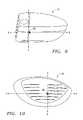
- FIG. 8is an isolated cross-sectional view of a face component of the golf club head overlapping an aft body.
- FIG. 9is a heel side plan view of a golf club of the present invention illustrating the Z-axis and X-axis.
- FIG. 10is a front plan view of a golf club of the present invention illustrating the Z-axis and Y-axis.
- FIG. 11is a front plan view of a golf club illustrating the test frame coordinates X T and Y T and transformed head frame coordinates Y H and Z H .
- FIG. 11Ais a toe end view of the golf club illustrating the test frame coordinate Z T and transformed head frame coordinates X H and Z H .
- FIG. 12is an isolated rear perspective view of the face component of the golf club.
- FIG. 13is an isolated front view of the face component of the golf club head.
- FIG. 13Ais an interior view of the face component of FIG. 13 .
- FIG. 13Bis a bottom plan view of the face component of FIG. 13 .
- FIG. 13Cis a top plan view of the face component of FIG. 13 .
- FIG. 13Dis a toe side view of the face component of FIG. 13 .
- FIG. 13Eis a heel side view of the face component of FIG. 13 .
- FIG. 14is an isolated top plan view of the aft-body of the golf club head.
- FIG. 14Ais an interior view of the aft-body of FIG. 14 .
- FIG. 14Bis a heel side view of the aft-body of FIG. 14 .
- FIG. 14Cis a toe side view of the aft-body of FIG. 14 .
- FIG. 14Dis a bottom plan view of the aft-body of FIG. 14 .
- FIG. 14Eis a rear view of the aft-body of FIG. 14 .
- FIG. 14Fis a bottom perspective view of the aft-body of FIG. 14 .
- a golf clubis generally designated 40 .
- the golf club 40has a golf club head 42 with a hollow interior, not shown.
- Engaging the club head 42is a shaft 48 that has a grip, not shown, at a butt end and is inserted into a hosel 54 at a tip end 56 .
- the club head 42is generally composed of two components, a face component 60 , and an aft-body 61 .
- the aft-body 61has a crown portion 62 and a sole portion 64 .
- the club head 42is preferably partitioned into a heel section 66 nearest the shaft 48 , a toe section 68 opposite the heel section 66 , and a rear section 70 opposite the face component 60 .
- a sole weighting member 133is disposed within a sole undercut portion 133 a of the sole portion.
- the sole weighting member 133has a mass ranging from 0.5 grams to 15 grams.
- the face component 60is generally composed of a metal material, and is preferably composed of a forged metal material. More preferably, the forged metal material is a forged aluminum alloy material. Such forged aluminum alloy materials include 7049, 7050 and 7075 die forged aluminum alloys and 7075 wrought aluminum alloy. Alternatively, the face component 60 is manufactured through casting, forming, machining, powdered metal forming, metal-injection-molding, electro chemical milling, and the like. The face component 60 may also be composed of other suitable materials, such as magnesium alloys.
- FIGS. 12 , 13 , 13 A, 13 B, 13 C, 13 D and 13 Eillustrate the face component 60 in isolation.
- the face component 60generally includes a striking plate portion (also referred to herein as a face plate) 72 and a return portion 74 extending laterally inward from the perimeter of the striking plate portion 72 .
- the striking plate portion 72typically has a plurality of scorelines 75 thereon.
- the striking plate portion 72preferably has a first layer 72 a and a second layer 72 b .
- the first layer 72 awhich includes the exterior surface of the striking plate portion 72 , is preferably formed with the return portion 74 as a single piece.
- the second layer 72 bis preferably attached to an interior surface of the first layer 72 a of the striking plate portion 72 .
- the second layer 72 bis preferably composed a high strength material such as a titanium alloy material, a steel alloy material, a beryllium-copper material, or a forging brass.
- the second layer 72 bpreferably has a thickness ranging from 0.020 inch to 0.080 inch, and more preferably from 0.030 inch to 0.060 inch, and most preferably 0.040 inch.
- the first layer 72 apreferably has a thickness ranging from 0.020 inch to 0.090 inch, more preferably 0.030 inch to 0.060 inch, and most preferably 0.050 inch.
- the first layer 72 ais preferably composed of a low density material such as an aluminum alloy, aluminum, magnesium alloys, and other like material.
- the first layer 72 apreferably has a density less than 5.0 grams per cubic centimeter (“g/cc”), and more preferably less than 3.0 g/cc.
- the second layer 72 bis preferably attached with an adhesive.
- the second layer 72 bis joined using a brazing alloy.
- the second layer 72 bis formed using explosion welding, such as disclosed in U.S. patent application Ser. No. 10/709,902, filed on Jun. 4, 2004, for A Golf Club Head With Face Insert, assigned to Callaway Golf Company, which pertinent parts are hereby incorporated by reference.
- the return portion 74generally includes an upper lateral section 76 , a lower lateral section 78 with a sole extension 95 , a heel lateral section 80 and a toe lateral section 82 .
- the return portion 74preferably encircles the striking plate portion 72 a full 360 degrees.
- the return portion 74may only encompass a partial section of the striking plate portion 72 , such as 270 degrees or 180 degrees, and may also be discontinuous.
- the upper lateral section 76extends inward, towards the aft-body 61 , a predetermined distance, d, to engage the crown 62 .
- the predetermined distanceranges from 0.2 inch to 1.0 inch, more preferably 0.40 inch to 0.75 inch, and most preferably 0.68 inch, as measured from the perimeter 73 of the striking plate portion 72 to the rearward edge of the upper lateral section 76 .
- the upper lateral section 76has a general curvature from the heel section 66 to the toe section 68 .
- the upper lateral section 76has a length from the perimeter 73 of the striking plate portion 72 that is preferably a minimal length near the center of the striking plate portion 72 , and increases toward the toe section 68 and the heel section 66 .
- the perimeter 73 of the striking plate portion 72is defined as the transition point where the face component 60 transitions from a plane substantially parallel to the striking plate portion 72 to a plane substantially perpendicular to the striking plate portion 72 .
- one method for determining the transition pointis to take a plane parallel to the striking plate portion 72 and a plane perpendicular to the striking plate portion 72 , and then take a plane at an angle of forty-five degrees to the parallel plane and the perpendicular plane. Where the forty-five degrees plane contacts the face component is the transition point thereby defining the perimeter of the striking plate portion 72 .
- the present inventionpreferably has the face component 60 engage the crown 62 along a substantially horizontal plane.
- the crown 62has a crown undercut portion 62 a , which is placed under the return portion 74 . Such an engagement enhances the flexibility of the striking plate portion 72 allowing for a greater coefficient of restitution.
- the crown 62 and the upper lateral section 76are attached to each other as further explained below.
- the heel lateral section 80is substantially perpendicular to the striking plate portion 72 , and the heel lateral section 80 covers the hosel 54 before engaging an optional ribbon section 90 and a bottom section 91 of the sole portion 64 of the aft-body 61 .
- the heel lateral section 80is attached to the sole portion 64 , both the ribbon 90 and the bottom section 91 , as explained in greater detail below.
- the heel lateral section 80extends inward a distance, d′′′, from the perimeter 73 a distance of 0.250 inch to 1.50 inches, more preferably 0.50 inch to 1.0 inch, and most preferably 0.950 inch.
- the heel lateral section 80preferably has a general curvature at its edge.
- the toe lateral section 82is attached to the sole portion 64 , both the ribbon 90 and the bottom section 91 , as explained in greater detail below.
- the toe lateral section 82extends inward a distance, d′′, from the perimeter 73 a distance of 0.250 inch to 1.50 inches, more preferably 0.75 inch to 1.30 inch, and most preferably 1.20 inch.
- the toe lateral section 82preferably has a general curvature at its edge.
- the lower lateral section 78extends inward, toward the aft-body 61 , a distance, d′, to engage the sole portion 64 , and a sole extension 95 extends further inward a distance d 5 to preferably function as protection for the sole of the club head 42 .
- the distance d′ranges from 0.2 inch to 1.25 inches, more preferably 0.50 inch to 1.10 inch, and most preferably 0.9 inch, as measured from the perimeter 73 of the striking plate portion 72 to the edge of the lower lateral section 78 .
- the distance d 5ranges from 0.2 inch to 3.0 inches, more preferably 0.50 inch to 2.0 inches, and most preferably 1.50 inch, as measured from the edge of the lower lateral section 78 to an apex 97 of the sole extension 95 .
- the sole extensionis triangular in shape with minor apices 99 .
- the sole extension 95has a crescent shape.
- the sole extension 95has a rectangular shape, and extends to the ribbon 90 .
- the sole portion 64has a sole undercut 64 a for placement under the return portion 74 .
- the sole extension 95is disposed within a sole undercut extension 64 aa .
- the sole portion 64 and the lower lateral section 78 , the heel lateral section 80 and the toe lateral section 82are attached to each other as explained in greater detail below.
- the aft-body 61is preferably composed of a non-metal material, preferably a composite material such as continuous fiber pre-preg material (including thermosetting materials or a thermoplastic materials for the resin). Other materials for the aft-body 61 include other thermosetting materials or other thermoplastic materials such as injectable plastics.
- the aft-body 61alternatively is composed of a low-density material. Preferable low-density metals include magnesium alloys, aluminum alloys, magnesium or aluminum material.
- Exemplary magnesium alloysare available from Phillips Plastics Corporation under the brands AZ-91-D (nominal composition of magnesium with aluminum, zinc and manganese), AM-60-B (nominal composition of magnesium with aluminum and manganese) and AM-50-A (nominal composition of magnesium with aluminum and manganese).
- the low-density metal aft-body 61is preferably manufactured through metal-injection-molding, casting, forming, machining, powdered metal forming, electro chemical milling, and the like.
- the non-metal aft-body 61is preferably manufactured through bladder-molding, resin transfer molding, resin infusion, injection molding, compression molding, or a similar process.
- the face component 60with an adhesive on the interior surface of the return portion 74 , is placed within a mold with a preform of the aft-body 61 for bladder molding.
- the return portion 74is placed and fitted into the undercut portions 62 a and 64 a .
- the adhesivemay be placed on the undercut portions 62 a and 64 a .
- Such adhesivesinclude thermosetting adhesives in a liquid or a film medium.
- a preferred adhesiveis a two part liquid epoxy sold by 3M of Minneapolis Minn. under the brand names DP420NS and DP460NS.
- Other alternative adhesivesinclude modified acrylic liquid adhesives such as DP810NS, also sold by the 3M company.
- foam tapessuch as Hysol Synspan may be utilized with the present invention.
- a bladderis placed within the hollow interior of the preform and face component 60 , and is pressurized within the mold, which is also subject to heating.
- the co-molding processsecures the aft-body 61 to the face component 60 .
- the aft-body 61is bonded to the face component 60 using an adhesive, or mechanically secured to the return portion 74 .
- the return portion 74overlaps the undercut portions 62 a and 64 a a distance Lo, which preferably ranges from 0.25 inch to 1.00 inch, more preferably ranges from 0.40 inch to 0.70 inch, and is most preferably 0.50 inch.
- An annular gap 170is created between an edge 190 of the crown portion 62 and the sole portion 64 , and an edge 195 of the return portion 74 .
- the annular gap 170preferably has a distance Lg that preferably ranges from 0.020 inch to 0.100 inch, more preferably from 0.050 inch to 0.070 inch, and is most preferably 0.060 inch.
- a projection 175 from an upper surface of the undercut portions 62 a and 64 aestablishes a minimum bond thickness between the interior surface of the return portion 74 and the upper surface of the undercut portions 62 a and 64 a .
- the bond thicknesspreferably ranges from 0.002 inch to 0.100 inch, more preferably ranges from 0.005 inch to 0.040 inch, and is most preferably 0.030 inch.
- a liquid adhesive 200preferably secures the aft body 61 to the face component 60 .
- a leading edge 180 of the undercut portions 62 a and 64 amay be sealed to prevent the liquid adhesive from entering the hollow interior 46 .
- FIGS. 14 , 14 A, 14 B, 14 C, 14 D, 14 E, and 14 Fillustrate a preferred embodiment of the aft-body 61 .
- the crown portion 62 of the aft-body 61is generally convex toward the sole portion 64 , and engages the ribbon 90 of sole portion 64 outside of the engagement with the face member 60 .
- the crown portion 62preferably has a thickness in the range of 0.010 to 0.100 inch, more preferably in the range of 0.025 inch to 0.070 inch, even more preferably in the range of 0.028 inch to 0.040 inch, and most preferably has a thickness of 0.033 inch.
- the sole portion 64including the bottom section 91 and the optional ribbon 90 which is substantially perpendicular to the bottom section 91 , preferably has a thickness in the range of 0.010 to 0.100 inch, more preferably in the range of 0.025 inch to 0.070 inch, even more preferably in the range of 0.028 inch to 0.040 inch, and most preferably has a thickness of 0.033 inch.
- the undercut portions 62 a , 64 a , 64 aa and 133 ahave a similar thickness to the sole portion 64 and the crown portion 62 .
- the aft-body 61is composed of a plurality of plies of pre-preg, typically six or seven plies, such as disclosed in U.S. Pat. No. 6,248,025, entitled Composite Golf Head And Method Of Manufacturing, which is hereby incorporated by reference in its entirety.
- the bottom section 91is generally convex toward the crown portion 62 .
- An optional bladder port 135is located in the sole undercut portion 64 a.
- FIG. 7illustrates the hollow interior 46 of the club head 42 of the present invention.
- the hosel 54( FIG. 12 ) is disposed within the hollow interior 46 , and is located as a part of the face component 60 .
- the hosel 54may be composed of a similar material to the face component 60 , and is preferably secured to the face component 60 through welding or the like.
- the hosel 54may also be formed with the formation of the face component 60 .
- the hosel 54may be composed of a non-similar material that is light weight and secured using bonding or other mechanical securing techniques.
- a hollow interior of the hosel 54is defined by a hosel wall that forms a tapering tube from the aperture 59 to the sole potion 64 .
- the hosel walldoes not engage the heel lateral section 80 thereby leaving a void 115 between the hosel wall and the heel lateral section 80 .
- the shaft 48is disposed within a hosel insert 121 that is disposed within the hosel 54 .
- a hosel insert 121 and hosel 54are described in U.S. Pat. No. 6,352,482, filed on Aug. 31, 2000, entitled Golf Club With Hosel Liner, which pertinent parts are hereby incorporated by reference.
- the hosel 54is preferably located rearward from the striking plate portion 72 in order to allow for compliance of the striking plate portion 72 during impact with a golf ball. In one embodiment, the hosel 54 is disposed 0.125 inch rearward from the striking plate portion 72 .
- a weighting member 122is preferably disposed within the hollow interior 46 of the club head 42 .
- the weighting member 122is disposed on the interior surface of the ribbon section 90 of the sole portion 64 in order to increase the moment of inertia and control the center of gravity of the golf club head 42 .
- the weighting member 122 , and additional weighting members 122may be placed in other locations of the club head 42 in order to influence the center of gravity, moment of inertia, or other inherent properties of the golf club head 42 .
- the weighting member 122is preferably tungsten loaded film, tungsten doped polymers, or similar weighting mechanisms such as described in U.S. Pat.
- the weight member 122is composed of three weighting components 122 a , 122 b and 122 c ( FIG. 14A ), which are embedded within the plies of pre-preg of the ribbon section 90 of the sole portion 64 of the aft-body 61 .
- a heel weight component 122 a , a center weight component 122 b and a toe weight component 122 care all disposed within the plies of pre-preg that compose the ribbon section 90 .
- each of the weight components 122 a–chas a mass ranging from 10 grams to 30 grams, preferably from 14 grams to 25 grams, and more preferably from 15 grams to 20 grams.
- Each of the weight components 122 a–chas a density ranging from 5 grams per cubic centimeters to 20 grams per cubic centimeters, more preferably from 7 grams per cubic centimeters to 12 grams per cubic centimeters, and most preferably 8.0 grams per cubic centimeters.
- Each of the weight components 122 a–cis preferably composed of a polymer material integrated with a metal material.
- the metal materialis preferably selected from copper, tungsten, steel, aluminum, tin, silver, gold, platinum, or the like.
- a preferred metalis tungsten due to its high density.
- the polymer materialis a thermoplastic or thermosetting polymer material.
- a preferred polymer materialis polyurethane, epoxy, nylon, polyester, or similar materials.
- a most preferred polymer materialis a thermoplastic polyurethane.
- a preferred weight component 122 a , 122 b or 122 cis an injection molded thermoplastic polyurethane integrated with tungsten to have a density of 8.0 grams per cubic centimeters.
- each of the weight components 122 a–care composed of from 50 to 95 volume percent polyurethane and from 50 to 5 volume percent tungsten. Also, in a preferred embodiment, each of the weight components 122 a–c are composed of from 10 to 25 weight percent polyurethane and from 90 to 75 weight percent tungsten.
- the weight components 122 a–cextend from approximately the heel section 66 of the striking plate portion 72 through the rear section 70 to the toe section 68 of the striking plate portion 72 .
- the weight components 122 a–cmay only extend along the rear section 70 of the ribbon section 90 , the heel section 66 of the ribbon section 90 , the toe section 68 of the ribbon section 90 , or any combination thereof.
- the weight components 122 a–cmay be positioned parallel to each other as opposed to being positioned in series.
- weighting materialsmay be utilized for the weight components 122 a–c without departing from the scope and spirit of the present invention.
- the placement of the weighting components 122 a–callows for the moment of inertia of the golf club head 40 to be optimized.
- Additional methods for manufacturing the face component 60include forming the face component 60 from a flat sheet of metal, super-plastic forming the face component 60 from a flat sheet of metal, machining the face component 60 from a solid block of metal, electrochemical milling the face from a forged pre-form, and like manufacturing methods. Yet further methods include diffusion bonding titanium sheets to yield a variable face thickness face and then superplastic forming.
- the face component 60is composed of an amorphous metal material such as disclosed in U.S. Pat. No. 6,471,604, which was filed on Apr. 4, 2002 and is hereby incorporated by reference in its entirety.
- the present inventionis directed at a golf club head that has a high coefficient of restitution thereby enabling for greater distance of a golf ball hit with the golf club head of the present invention.
- U 1is the club head velocity prior to impact
- U 2is the golf ball velocity prior to impact which is zero
- v 1is the club head velocity just after separation of the golf ball from the face of the club head
- v 2is the golf ball velocity just after separation of the golf ball from the face of the club head
- eis the coefficient of restitution between the golf ball and the club face.
- the values of eare limited between zero and 1.0 for systems with no energy addition.
- the coefficient of restitution, e, for a material such as a soft clay or puttywould be near zero, while for a perfectly elastic material, where no energy is lost as a result of deformation, the value of e would be 1.0.
- the present inventionprovides a club head having a coefficient of restitution ranging from 0.81 to 0.94, as measured under conventional test conditions.
- the coefficient of restitution of the club head 42 of the present invention under standard USGA test conditions with a given ballranges from approximately 0.81 to 0.94, preferably ranges from 0.83 to 0.883 and is most preferably 0.87.
- the striking plate portion 72 of the face component 60has a smaller aspect ratio than face plates of the prior art.
- the aspect ratio as used hereinis defined as the width, “W”, of the face divided by the height, “H”, of the face, as shown in FIG. 1A .
- the width Wis 78 millimeters and the height H is 48 millimeters giving an aspect ratio of 1.625.
- the aspect ratiois usually much greater than 1.
- the original GREAT BIG BERTHA® driverhad an aspect ratio of 1.9.
- the striking plate portion 72 of the present inventionhas an aspect ratio that is no greater than 1.7.
- the aspect ratio of the present inventionpreferably ranges from 1.0 to 1.7.
- One embodimenthas an aspect ratio of 1.3.
- the striking plate portion 72 of the present inventionis more circular than faces of the prior art.
- the face area of the striking plate portion 72 of the present inventionranges from 4.00 square inches to 7.50 square inches, more preferably from 5.00 square inches to 6.5 square inches, and most preferably from 5.8 square inches to 6.0 square inches.
- the club head 42 of the present inventionalso has a greater volume than a club head of the prior art while maintaining a weight that is substantially equivalent to that of the prior art.
- the volume of the club head 42 of the present inventionranges from 290 cubic centimeters to 600 cubic centimeters, and more preferably ranges from 350 cubic centimeters to 510 cubic centimeters, even preferably 385 cubic centimeters to 475 cubic centimeters, and most preferably 460 cubic centimeters.
- the mass of the club head 42 of the present inventionranges from 165 grams to 225 grams, preferably ranges from 175 grams to 205 grams, and most preferably from 190 grams to 200 grams.
- the face component 60has a mass ranging from 50 grams to 110 grams, more preferably ranging from 65 grams to 95 grams, yet more preferably from 70 grams to 90 grams, and most preferably 78 grams.
- the aft-body 61(without weighting) has a mass preferably ranging from 10 grams to 60 grams, more preferably from 15 grams to 50 grams, and most preferably 35 grams to 40 grams.
- the weighting member 122(preferably composed of three separate weighting members 122 a , 122 b and 122 c ) has a mass preferably ranging from 30 grams to 120 grams, more preferably from 50 grams to 80 grams, and most preferably 60 grams.
- the interior hosel 54preferably a mass preferably ranging from 3 grams to 20 grams, more preferably from 5 grams to 15 grams, and most preferably 12 grams. Additionally, epoxy, or other like flowable materials, in an amount ranging from 0.5 grams to 5 grams, may be injected into the hollow interior 46 of the golf club head 42 for selective weighting thereof.
- the depth of the club head 42 from the striking plate portion 72 to the rear section of the crown portion 62preferably ranges from 3.0 inches to 4.5 inches, and is most preferably 3.5 inches.
- the height, “h”, of the club head 42as measured while in striking position, preferably ranges from 2.0 inches to 3.5 inches, and is most preferably 2.50 inches.
- the width, “w”, of the club head 42 from the toe section 68 to the heel section 66preferably ranges from 4.0 inches to 5.0 inches, and more preferably 4.4 inches.
- FIGS. 10 and 10Aillustrate the axes of inertia through the center of gravity of the golf club head.
- the axes of inertiaare designated X, Y and Z.
- the X-axisextends from the striking plate portion 72 through the center of gravity, CG, and to the rear of the golf club head 42 .
- the Y-axisextends from the toe section 68 of the golf club head 42 through the center of gravity, CG, and to the heel section 66 of the golf club head 42 .
- the Z-axisextends from the crown portion 62 through the center of gravity, CG, and to the sole portion 64 .
- the center of gravity, or center of mass, of the golf club headis a point inside of the club head determined by the vertical intersection of two or more points where the club head balances when suspended. A more thorough explanation of this definition of the center of gravity is provided in Golf Club Design, Fitting, Alteration & Repair.
- the center of gravity and the moment of inertia of a golf club head 42are preferably measured using a test frame (X T , Y T , Z T ), and then transformed to a head frame (X H , Y H , Z H ), as shown in FIGS. 11 and 11A .
- the center of gravity of a golf club headmay be obtained using a center of gravity table having two weight scales thereon, as disclosed in U.S. Pat. No. 6,607,452, entitled High Moment Of Inertia Composite Golf Club, and hereby incorporated by reference in its entirety. If a shaft is present, it is removed and replaced with a hosel cube that has a multitude of faces normal to the axes of the golf club head. Given the weight of the golf club head, the scales allow one to determine the weight distribution of the golf club head when the golf club head is placed on both scales simultaneously and weighed along a particular direction, the X, Y or Z direction.
- the moment of inertia, Izz, about the Z-axis for the golf club head 42 of the present inventionwill range from 2800 g-cm 2 to 5000 g-cm 2 , preferably from 3000 g-cm 2 to 4500 g-cm 2 , and most preferably from 3750 g-cm 2 to 4250 g-cm 2 .
- the moment of inertia, Iyy, about the Y-axis for the golf club head 42 of the present inventionwill range from 1500 g-cm 2 to 2750 g-cm 2 , preferably from 2000 g-cm 2 to 2400 g-cm 2 , and most preferably from 2100 g-cm 2 to 2300 g-cm 2 .
- the golf club head 42has products of inertia such as disclosed in U.S. Pat. No. 6,425,832, and is hereby incorporated by reference in its entirety.
- each of the products of inertia, Ixy, Ixz and Iyz, of the golf club head 42have an absolute value less than 100 grams-centimeter squared.
Landscapes
- Health & Medical Sciences (AREA)
- General Health & Medical Sciences (AREA)
- Physical Education & Sports Medicine (AREA)
- Life Sciences & Earth Sciences (AREA)
- Engineering & Computer Science (AREA)
- Wood Science & Technology (AREA)
- Golf Clubs (AREA)
Abstract
Description
e=v2−v1
U1−U2
Claims (9)
Priority Applications (5)
| Application Number | Priority Date | Filing Date | Title |
|---|---|---|---|
| US10/711,849US7121957B2 (en) | 2004-10-08 | 2004-10-08 | Multiple material golf club head |
| PCT/US2005/036383WO2006042205A1 (en) | 2004-10-08 | 2005-10-06 | Multiple material golf club head |
| JP2007535882AJP2008515561A (en) | 2004-10-08 | 2005-10-06 | Composite golf club head |
| CNA2005800423698ACN101076381A (en) | 2004-10-08 | 2005-10-06 | Multiple material golf club head |
| GB0706808AGB2432793B (en) | 2004-10-08 | 2005-10-06 | Multiple material golf club head |
Applications Claiming Priority (1)
| Application Number | Priority Date | Filing Date | Title |
|---|---|---|---|
| US10/711,849US7121957B2 (en) | 2004-10-08 | 2004-10-08 | Multiple material golf club head |
Publications (2)
| Publication Number | Publication Date |
|---|---|
| US20060079346A1 US20060079346A1 (en) | 2006-04-13 |
| US7121957B2true US7121957B2 (en) | 2006-10-17 |
Family
ID=36146067
Family Applications (1)
| Application Number | Title | Priority Date | Filing Date |
|---|---|---|---|
| US10/711,849Expired - LifetimeUS7121957B2 (en) | 2004-10-08 | 2004-10-08 | Multiple material golf club head |
Country Status (5)
| Country | Link |
|---|---|
| US (1) | US7121957B2 (en) |
| JP (1) | JP2008515561A (en) |
| CN (1) | CN101076381A (en) |
| GB (1) | GB2432793B (en) |
| WO (1) | WO2006042205A1 (en) |
Cited By (39)
| Publication number | Priority date | Publication date | Assignee | Title |
|---|---|---|---|---|
| US20070293351A1 (en)* | 1999-11-01 | 2007-12-20 | Callaway Golf Company | Multiple material golf club head |
| US20110065528A1 (en)* | 2009-09-15 | 2011-03-17 | Callaway Golf Company | Multiple material golf club head and a method for forming a golf club head |
| US20110218053A1 (en)* | 2010-03-05 | 2011-09-08 | Callaway Golf Company | Golf club head |
| US8151685B2 (en) | 2006-09-15 | 2012-04-10 | Force Protection Industries, Inc. | Apparatus for defeating high energy projectiles |
| US8177659B1 (en) | 2010-12-10 | 2012-05-15 | Callaway Golf Company | Golf club head with improved aerodynamic characteristics |
| US8197358B1 (en) | 2009-12-16 | 2012-06-12 | Callaway Golf Company | Golf club head with composite weight port |
| US8485919B2 (en) | 2009-12-16 | 2013-07-16 | Callaway Golf Company | Golf club head with composite weight port |
| US8540588B2 (en) | 2009-12-16 | 2013-09-24 | Bradley C. Rice | Golf club head with composite weight port |
| US8585510B1 (en) | 2010-08-30 | 2013-11-19 | Callaway Golf Company | Golf club head with improved aerodynamic characteristics |
| US8684859B1 (en) | 2011-03-10 | 2014-04-01 | Callaway Golf Company | Adjustable golf club shaft and hosel assembly |
| US8696486B1 (en) | 2011-03-10 | 2014-04-15 | Callaway Golf Company | Adjustable golf club shaft and hosel assembly |
| US8715102B1 (en) | 2011-03-10 | 2014-05-06 | Callaway Golf Company | Adjustable golf club shaft and hosel assembly |
| US8721471B2 (en) | 2010-06-01 | 2014-05-13 | Taylor Made Golf Company, Inc. | Hollow golf club head having sole stress reducing feature |
| US8753221B1 (en) | 2012-01-26 | 2014-06-17 | Callaway Golf Company | Adjustable golf club shaft and hosel assembly |
| US8821312B2 (en) | 2010-06-01 | 2014-09-02 | Taylor Made Golf Company, Inc. | Golf club head having a stress reducing feature with aperture |
| US8827831B2 (en) | 2010-06-01 | 2014-09-09 | Taylor Made Golf Company, Inc. | Golf club head having a stress reducing feature |
| US9089749B2 (en) | 2010-06-01 | 2015-07-28 | Taylor Made Golf Company, Inc. | Golf club head having a shielded stress reducing feature |
| US9597561B1 (en)* | 2015-06-30 | 2017-03-21 | Callaway Golf Company | Golf club head having face stress-reduction features |
| US9925432B2 (en) | 2016-05-27 | 2018-03-27 | Karsten Manufacturing Corporation | Mixed material golf club head |
| US20190262669A1 (en)* | 2018-02-28 | 2019-08-29 | Sumitomo Rubber Industries, Ltd. | Golf club head |
| US10486042B1 (en)* | 2018-05-17 | 2019-11-26 | Callaway Golf Company | Golf club head with adjustable center of gravity |
| US10675514B2 (en) | 2018-01-19 | 2020-06-09 | Karsten Manufacturing Corporation | Mixed material golf club head |
| US10806977B2 (en) | 2018-01-19 | 2020-10-20 | Karsten Manufacturing Corporation | Golf club heads comprising a thermoplastic composite material |
| US10828543B2 (en) | 2016-05-27 | 2020-11-10 | Karsten Manufacturing Corporation | Mixed material golf club head |
| US10874915B2 (en) | 2017-08-10 | 2020-12-29 | Taylor Made Golf Company, Inc. | Golf club heads |
| US10888747B2 (en) | 2008-07-15 | 2021-01-12 | Taylor Made Golf Company, Inc. | Aerodynamic golf club head |
| US10940373B2 (en) | 2016-05-27 | 2021-03-09 | Karsten Manufacturing Corporation | Mixed material golf club head |
| US10940374B2 (en) | 2016-05-27 | 2021-03-09 | Karsten Manufacturing Corporation | Mixed material golf club head |
| US10967232B2 (en)* | 2019-05-15 | 2021-04-06 | Karsten Manufacturing Corporation | Club head having balanced impact and swing performance characteristics |
| USD916992S1 (en) | 2019-08-09 | 2021-04-20 | Karsten Manufacturing Corporation | Multi-component golf club head |
| US11045694B2 (en) | 2008-07-15 | 2021-06-29 | Taylor Made Golf Company, Inc. | Aerodynamic golf club head |
| US11130026B2 (en) | 2008-07-15 | 2021-09-28 | Taylor Made Golf Company, Inc. | Aerodynamic golf club head |
| US11517799B2 (en) | 2017-12-08 | 2022-12-06 | Karsten Manufacturing Corporation | Multi-component golf club head |
| US11701557B2 (en) | 2017-08-10 | 2023-07-18 | Taylor Made Golf Company, Inc. | Golf club heads |
| US11786784B1 (en) | 2022-12-16 | 2023-10-17 | Topgolf Callaway Brands Corp. | Golf club head |
| US11819743B2 (en) | 2016-05-27 | 2023-11-21 | Karsten Manufacturing Corporation | Mixed material golf club head |
| US11839802B2 (en) | 2017-12-08 | 2023-12-12 | Karsten Manufacturing Corporation | Multi-component golf club head |
| US11969632B2 (en) | 2016-05-27 | 2024-04-30 | Karsten Manufacturing Corporation | Mixed material golf club head |
| US12128278B2 (en) | 2008-07-15 | 2024-10-29 | Taylor Made Golf Company, Inc. | Aerodynamic golf club head |
Families Citing this family (11)
| Publication number | Priority date | Publication date | Assignee | Title |
|---|---|---|---|---|
| US7214143B2 (en)* | 2005-03-18 | 2007-05-08 | Callaway Golf Company | Golf club head with a face insert |
| US20090293709A1 (en)* | 2008-05-27 | 2009-12-03 | Joynt Vernon P | Apparatus for defeating high energy projectiles |
| US8337323B2 (en)* | 2010-10-22 | 2012-12-25 | Sri Sports Limited | Golf club head |
| JP5756731B2 (en)* | 2011-10-12 | 2015-07-29 | ダンロップスポーツ株式会社 | Golf club |
| JP6533543B2 (en)* | 2016-02-23 | 2019-06-19 | キャラウェイ・ゴルフ・カンパニ | Golf club head with optimized ball speed vs. CT relationship |
| JP6611364B2 (en)* | 2016-12-20 | 2019-11-27 | キャラウェイ・ゴルフ・カンパニ | Golf club head with optimized ball speed vs. CT |
| US10207160B2 (en)* | 2016-12-30 | 2019-02-19 | Taylor Made Golf Company, Inc. | Golf club heads |
| US20180345099A1 (en) | 2017-06-05 | 2018-12-06 | Taylor Made Golf Company, Inc. | Golf club heads |
| EP3894026A4 (en)* | 2018-12-13 | 2022-08-24 | Karsten Manufacturing Corporation | MIXED MATERIAL GOLF CLUB HEAD |
| JP2022024302A (en)* | 2020-07-15 | 2022-02-09 | ブリヂストンスポーツ株式会社 | Golf club head |
| JP2022024303A (en)* | 2020-07-15 | 2022-02-09 | ブリヂストンスポーツ株式会社 | Golf club head |
Citations (43)
| Publication number | Priority date | Publication date | Assignee | Title |
|---|---|---|---|---|
| US1167387A (en) | 1913-11-01 | 1916-01-11 | Percy Gordon Eckersley Daniel | Golf-club and the like. |
| US1780625A (en) | 1924-04-17 | 1930-11-04 | Crawford Mcgregor & Canby Co | Golf-club head |
| US2750194A (en) | 1955-01-24 | 1956-06-12 | Austin N Clark | Golf club head with weight adjustment |
| US3692306A (en) | 1971-02-18 | 1972-09-19 | Cecil C Glover | Golf club having integrally formed face and sole plate with weight means |
| US3897066A (en) | 1973-11-28 | 1975-07-29 | Peter A Belmont | Golf club heads and process |
| US3937474A (en) | 1971-03-10 | 1976-02-10 | Acushnet Company | Golf club with polyurethane insert |
| US3975023A (en) | 1971-12-13 | 1976-08-17 | Kyoto Ceramic Co., Ltd. | Golf club head with ceramic face plate |
| US3989248A (en) | 1974-12-26 | 1976-11-02 | Pepsico, Inc. | Golf club having insert capable of elastic flexing |
| US4021047A (en) | 1976-02-25 | 1977-05-03 | Mader Robert J | Golf driver club |
| US4398965A (en) | 1976-10-26 | 1983-08-16 | Pepsico, Inc. | Method of making iron golf clubs with flexible impact surface |
| US4568088A (en) | 1982-10-19 | 1986-02-04 | Sumitomo Rubber Industries, Ltd. | Golf club head |
| US4872685A (en) | 1988-11-14 | 1989-10-10 | Sun Donald J C | Golf club head with impact insert member |
| US4877249A (en) | 1986-11-10 | 1989-10-31 | Thompson Stanley C | Golf club head and method of strengthening same |
| US5106094A (en) | 1989-06-01 | 1992-04-21 | Salomon S.A. | Golf club head and process of manufacturing thereof |
| US5193811A (en) | 1990-11-09 | 1993-03-16 | The Yokohama Rubber Co., Ltd. | Wood type golf club head |
| US5282624A (en) | 1990-01-31 | 1994-02-01 | Taylor Made Company, Inc. | Golf club head |
| US5288070A (en)* | 1993-03-09 | 1994-02-22 | Chen Archer C C | Golf club head of composite material |
| US5310185A (en) | 1992-02-27 | 1994-05-10 | Taylor Made Golf Company | Golf club head and processes for its manufacture |
| US5322206A (en)* | 1991-03-19 | 1994-06-21 | Yamaha Corporation | Golf club head and a process for producing the same |
| US5344140A (en) | 1989-06-12 | 1994-09-06 | Donald A. Anderson | Golf club head and method of forming same |
| US5346216A (en) | 1992-02-27 | 1994-09-13 | Daiwa Golf Co., Ltd. | Golf club head |
| US5377986A (en) | 1992-02-27 | 1995-01-03 | Taylor Made Golf Company, Inc. | Process for manufacture of a golf club head comprising a mounted hitting surface |
| US5398935A (en) | 1990-11-29 | 1995-03-21 | Maruman Golf Kabushiki Kaisha | Golf wood clubhead |
| US5410798A (en) | 1994-01-06 | 1995-05-02 | Lo; Kun-Nan | Method for producing a composite golf club head |
| US5425538A (en) | 1991-07-11 | 1995-06-20 | Taylor Made Golf Company, Inc. | Golf club head having a fiber-based composite impact wall |
| US5499814A (en) | 1994-09-08 | 1996-03-19 | Lu; Clive S. | Hollow club head with deflecting insert face plate |
| US5516107A (en) | 1991-08-13 | 1996-05-14 | The Yokohama Rubber Co., Ltd. | Wood type golf club head |
| US5547427A (en) | 1992-04-01 | 1996-08-20 | Taylor Made Golf Company, Inc. | Golf club head having a hollow plastic body and a metallic sealing element |
| US5570886A (en) | 1992-04-01 | 1996-11-05 | Taylor Made Golf Company, Inc. | Golf club head having an inner subassembly and an outer casing and method of manufacture |
| US5624331A (en) | 1995-10-30 | 1997-04-29 | Pro-Kennex, Inc. | Composite-metal golf club head |
| US5669827A (en)* | 1995-02-27 | 1997-09-23 | Yamaha Corporation | Metallic wood club head for golf |
| US5743813A (en) | 1997-02-19 | 1998-04-28 | Chien Ting Precision Casting Co., Ltd. | Golf club head |
| US5776011A (en) | 1996-09-27 | 1998-07-07 | Echelon Golf | Golf club head |
| US5863261A (en)* | 1996-03-27 | 1999-01-26 | Demarini Sports, Inc. | Golf club head with elastically deforming face and back plates |
| US6146571A (en) | 1992-09-18 | 2000-11-14 | Taylor Made Golf Co., Inc. | Method of manufacturing a golf club head by plastic injection using inserts meltable core, and a golf club head manufactured by the method |
| US6149534A (en) | 1998-11-02 | 2000-11-21 | Taylor Made Golf Company, Inc. | Bi-metallic golf club head with single plane interface |
| US6299547B1 (en)* | 1999-12-30 | 2001-10-09 | Callaway Golf Company | Golf club head with an internal striking plate brace |
| US6428427B1 (en)* | 2000-10-03 | 2002-08-06 | Callaway Golf Company | Golf club head with coated striking plate |
| US6471604B2 (en)* | 1999-11-01 | 2002-10-29 | Callaway Golf Company | Multiple material golf head |
| US6491532B1 (en)* | 2001-06-29 | 2002-12-10 | Delphi Technologies, Inc. | Arc suppressed electrical connectors |
| US6565452B2 (en)* | 1999-11-01 | 2003-05-20 | Callaway Golf Company | Multiple material golf club head with face insert |
| US6602149B1 (en)* | 2002-03-25 | 2003-08-05 | Callaway Golf Company | Bonded joint design for a golf club head |
| US6638180B2 (en)* | 2001-07-31 | 2003-10-28 | K.K. Endo Seisakusho | Golf club |
- 2004
- 2004-10-08USUS10/711,849patent/US7121957B2/ennot_activeExpired - Lifetime
- 2005
- 2005-10-06GBGB0706808Apatent/GB2432793B/ennot_activeExpired - Fee Related
- 2005-10-06WOPCT/US2005/036383patent/WO2006042205A1/enactiveApplication Filing
- 2005-10-06JPJP2007535882Apatent/JP2008515561A/enactivePending
- 2005-10-06CNCNA2005800423698Apatent/CN101076381A/enactivePending
Patent Citations (44)
| Publication number | Priority date | Publication date | Assignee | Title |
|---|---|---|---|---|
| US1167387A (en) | 1913-11-01 | 1916-01-11 | Percy Gordon Eckersley Daniel | Golf-club and the like. |
| US1780625A (en) | 1924-04-17 | 1930-11-04 | Crawford Mcgregor & Canby Co | Golf-club head |
| US2750194A (en) | 1955-01-24 | 1956-06-12 | Austin N Clark | Golf club head with weight adjustment |
| US3692306A (en) | 1971-02-18 | 1972-09-19 | Cecil C Glover | Golf club having integrally formed face and sole plate with weight means |
| US3937474A (en) | 1971-03-10 | 1976-02-10 | Acushnet Company | Golf club with polyurethane insert |
| US3975023A (en) | 1971-12-13 | 1976-08-17 | Kyoto Ceramic Co., Ltd. | Golf club head with ceramic face plate |
| US3897066A (en) | 1973-11-28 | 1975-07-29 | Peter A Belmont | Golf club heads and process |
| US3989248A (en) | 1974-12-26 | 1976-11-02 | Pepsico, Inc. | Golf club having insert capable of elastic flexing |
| US4021047A (en) | 1976-02-25 | 1977-05-03 | Mader Robert J | Golf driver club |
| US4398965A (en) | 1976-10-26 | 1983-08-16 | Pepsico, Inc. | Method of making iron golf clubs with flexible impact surface |
| US4568088A (en) | 1982-10-19 | 1986-02-04 | Sumitomo Rubber Industries, Ltd. | Golf club head |
| US4877249A (en) | 1986-11-10 | 1989-10-31 | Thompson Stanley C | Golf club head and method of strengthening same |
| US4872685A (en) | 1988-11-14 | 1989-10-10 | Sun Donald J C | Golf club head with impact insert member |
| US5106094A (en) | 1989-06-01 | 1992-04-21 | Salomon S.A. | Golf club head and process of manufacturing thereof |
| US5344140A (en) | 1989-06-12 | 1994-09-06 | Donald A. Anderson | Golf club head and method of forming same |
| US5282624A (en) | 1990-01-31 | 1994-02-01 | Taylor Made Company, Inc. | Golf club head |
| US5193811A (en) | 1990-11-09 | 1993-03-16 | The Yokohama Rubber Co., Ltd. | Wood type golf club head |
| US5398935A (en) | 1990-11-29 | 1995-03-21 | Maruman Golf Kabushiki Kaisha | Golf wood clubhead |
| US5322206A (en)* | 1991-03-19 | 1994-06-21 | Yamaha Corporation | Golf club head and a process for producing the same |
| US5425538A (en) | 1991-07-11 | 1995-06-20 | Taylor Made Golf Company, Inc. | Golf club head having a fiber-based composite impact wall |
| US5516107A (en) | 1991-08-13 | 1996-05-14 | The Yokohama Rubber Co., Ltd. | Wood type golf club head |
| US5310185A (en) | 1992-02-27 | 1994-05-10 | Taylor Made Golf Company | Golf club head and processes for its manufacture |
| US5346216A (en) | 1992-02-27 | 1994-09-13 | Daiwa Golf Co., Ltd. | Golf club head |
| US5377986A (en) | 1992-02-27 | 1995-01-03 | Taylor Made Golf Company, Inc. | Process for manufacture of a golf club head comprising a mounted hitting surface |
| US5547427A (en) | 1992-04-01 | 1996-08-20 | Taylor Made Golf Company, Inc. | Golf club head having a hollow plastic body and a metallic sealing element |
| US5570886A (en) | 1992-04-01 | 1996-11-05 | Taylor Made Golf Company, Inc. | Golf club head having an inner subassembly and an outer casing and method of manufacture |
| US6146571A (en) | 1992-09-18 | 2000-11-14 | Taylor Made Golf Co., Inc. | Method of manufacturing a golf club head by plastic injection using inserts meltable core, and a golf club head manufactured by the method |
| US5288070A (en)* | 1993-03-09 | 1994-02-22 | Chen Archer C C | Golf club head of composite material |
| US5410798A (en) | 1994-01-06 | 1995-05-02 | Lo; Kun-Nan | Method for producing a composite golf club head |
| US5499814A (en) | 1994-09-08 | 1996-03-19 | Lu; Clive S. | Hollow club head with deflecting insert face plate |
| US5669827A (en)* | 1995-02-27 | 1997-09-23 | Yamaha Corporation | Metallic wood club head for golf |
| US5624331A (en) | 1995-10-30 | 1997-04-29 | Pro-Kennex, Inc. | Composite-metal golf club head |
| US5863261A (en)* | 1996-03-27 | 1999-01-26 | Demarini Sports, Inc. | Golf club head with elastically deforming face and back plates |
| US5776011A (en) | 1996-09-27 | 1998-07-07 | Echelon Golf | Golf club head |
| US5743813A (en) | 1997-02-19 | 1998-04-28 | Chien Ting Precision Casting Co., Ltd. | Golf club head |
| US6149534A (en) | 1998-11-02 | 2000-11-21 | Taylor Made Golf Company, Inc. | Bi-metallic golf club head with single plane interface |
| US6565452B2 (en)* | 1999-11-01 | 2003-05-20 | Callaway Golf Company | Multiple material golf club head with face insert |
| US6471604B2 (en)* | 1999-11-01 | 2002-10-29 | Callaway Golf Company | Multiple material golf head |
| US6491592B2 (en)* | 1999-11-01 | 2002-12-10 | Callaway Golf Company | Multiple material golf club head |
| US6299547B1 (en)* | 1999-12-30 | 2001-10-09 | Callaway Golf Company | Golf club head with an internal striking plate brace |
| US6428427B1 (en)* | 2000-10-03 | 2002-08-06 | Callaway Golf Company | Golf club head with coated striking plate |
| US6491532B1 (en)* | 2001-06-29 | 2002-12-10 | Delphi Technologies, Inc. | Arc suppressed electrical connectors |
| US6638180B2 (en)* | 2001-07-31 | 2003-10-28 | K.K. Endo Seisakusho | Golf club |
| US6602149B1 (en)* | 2002-03-25 | 2003-08-05 | Callaway Golf Company | Bonded joint design for a golf club head |
Cited By (101)
| Publication number | Priority date | Publication date | Assignee | Title |
|---|---|---|---|---|
| US20080064525A1 (en)* | 1999-11-01 | 2008-03-13 | Callaway Golf Company | Multiple material golf club head |
| US7491134B2 (en)* | 1999-11-01 | 2009-02-17 | Callaway Golf Company | Multiple material golf club head |
| US7497787B2 (en)* | 1999-11-01 | 2009-03-03 | Callaway Golf Club | Multiple material golf club head |
| US20070293351A1 (en)* | 1999-11-01 | 2007-12-20 | Callaway Golf Company | Multiple material golf club head |
| US8151685B2 (en) | 2006-09-15 | 2012-04-10 | Force Protection Industries, Inc. | Apparatus for defeating high energy projectiles |
| US12364908B2 (en) | 2008-07-15 | 2025-07-22 | Taylor Made Golf Company, Inc. | Aerodynamic golf club head |
| US11130026B2 (en) | 2008-07-15 | 2021-09-28 | Taylor Made Golf Company, Inc. | Aerodynamic golf club head |
| US11045694B2 (en) | 2008-07-15 | 2021-06-29 | Taylor Made Golf Company, Inc. | Aerodynamic golf club head |
| US11633651B2 (en) | 2008-07-15 | 2023-04-25 | Taylor Made Golf Company, Inc. | Aerodynamic golf club head |
| US12128278B2 (en) | 2008-07-15 | 2024-10-29 | Taylor Made Golf Company, Inc. | Aerodynamic golf club head |
| US11707652B2 (en) | 2008-07-15 | 2023-07-25 | Taylor Made Golf Company, Inc. | Aerodynamic golf club head |
| US11465019B2 (en) | 2008-07-15 | 2022-10-11 | Taylor Made Golf Company, Inc. | Aerodynamic golf club head |
| US10888747B2 (en) | 2008-07-15 | 2021-01-12 | Taylor Made Golf Company, Inc. | Aerodynamic golf club head |
| US12070663B2 (en) | 2008-07-15 | 2024-08-27 | Taylor Made Golf Company, Inc. | Aerodynamic golf club head |
| US8425349B2 (en)* | 2009-09-15 | 2013-04-23 | Callaway Golf Company | Multiple material golf club head and a method for forming a golf club head |
| US20110065528A1 (en)* | 2009-09-15 | 2011-03-17 | Callaway Golf Company | Multiple material golf club head and a method for forming a golf club head |
| US8540588B2 (en) | 2009-12-16 | 2013-09-24 | Bradley C. Rice | Golf club head with composite weight port |
| US8485919B2 (en) | 2009-12-16 | 2013-07-16 | Callaway Golf Company | Golf club head with composite weight port |
| US8444506B2 (en) | 2009-12-16 | 2013-05-21 | Callaway Golf Company | Golf club head with composite weight port |
| US8197358B1 (en) | 2009-12-16 | 2012-06-12 | Callaway Golf Company | Golf club head with composite weight port |
| US8435134B2 (en) | 2010-03-05 | 2013-05-07 | Callaway Golf Company | Golf club head |
| US8632419B2 (en) | 2010-03-05 | 2014-01-21 | Callaway Golf Company | Golf club head |
| US20110218053A1 (en)* | 2010-03-05 | 2011-09-08 | Callaway Golf Company | Golf club head |
| US12296238B2 (en) | 2010-06-01 | 2025-05-13 | Taylor Made Golf Company, Inc. | Multi-material iron-type golf club head |
| US10300350B2 (en) | 2010-06-01 | 2019-05-28 | Taylor Made Golf Company, Inc. | Golf club having sole stress reducing feature |
| US9011267B2 (en) | 2010-06-01 | 2015-04-21 | Taylor Made Golf Company, Inc. | Golf club head having a stress reducing feature and shaft connection system socket |
| US9089749B2 (en) | 2010-06-01 | 2015-07-28 | Taylor Made Golf Company, Inc. | Golf club head having a shielded stress reducing feature |
| US9168428B2 (en) | 2010-06-01 | 2015-10-27 | Taylor Made Golf Company, Inc. | Hollow golf club head having sole stress reducing feature |
| US9168434B2 (en) | 2010-06-01 | 2015-10-27 | Taylor Made Golf Company, Inc. | Golf club head having a stress reducing feature with aperture |
| US9174101B2 (en) | 2010-06-01 | 2015-11-03 | Taylor Made Golf Company, Inc. | Golf club head having a stress reducing feature |
| US9265993B2 (en) | 2010-06-01 | 2016-02-23 | Taylor Made Golf Company, Inc | Hollow golf club head having crown stress reducing feature |
| US9566479B2 (en) | 2010-06-01 | 2017-02-14 | Taylor Made Golf Company, Inc. | Golf club head having sole stress reducing feature |
| US11351425B2 (en) | 2010-06-01 | 2022-06-07 | Taylor Made Golf Company, Inc. | Multi-material iron-type golf club head |
| US9610482B2 (en) | 2010-06-01 | 2017-04-04 | Taylor Made Golf Company, Inc | Golf club head having a stress reducing feature with aperture |
| US9610483B2 (en) | 2010-06-01 | 2017-04-04 | Taylor Made Golf Company, Inc | Iron-type golf club head having a sole stress reducing feature |
| US9656131B2 (en) | 2010-06-01 | 2017-05-23 | Taylor Made Golf Company, Inc. | Golf club head having a stress reducing feature and shaft connection system socket |
| US8821312B2 (en) | 2010-06-01 | 2014-09-02 | Taylor Made Golf Company, Inc. | Golf club head having a stress reducing feature with aperture |
| US9950223B2 (en) | 2010-06-01 | 2018-04-24 | Taylor Made Golf Company, Inc. | Golf club head having a stress reducing feature with aperture |
| US9950222B2 (en) | 2010-06-01 | 2018-04-24 | Taylor Made Golf Company, Inc. | Golf club having sole stress reducing feature |
| US9956460B2 (en) | 2010-06-01 | 2018-05-01 | Taylor Made Golf Company, Inc | Golf club head having a stress reducing feature and shaft connection system socket |
| US10245485B2 (en) | 2010-06-01 | 2019-04-02 | Taylor Made Golf Company Inc. | Golf club head having a stress reducing feature with aperture |
| US12357883B2 (en) | 2010-06-01 | 2025-07-15 | Taylor Made Golf Company, Inc. | Golf club head having a shaft connection system socket |
| US8827831B2 (en) | 2010-06-01 | 2014-09-09 | Taylor Made Golf Company, Inc. | Golf club head having a stress reducing feature |
| US10369429B2 (en) | 2010-06-01 | 2019-08-06 | Taylor Made Golf Company, Inc. | Golf club head having a stress reducing feature and shaft connection system socket |
| US11045696B2 (en) | 2010-06-01 | 2021-06-29 | Taylor Made Golf Company, Inc. | Iron-type golf club head |
| US11364421B2 (en) | 2010-06-01 | 2022-06-21 | Taylor Made Golf Company, Inc. | Golf club head having a shaft connection system socket |
| US10556160B2 (en) | 2010-06-01 | 2020-02-11 | Taylor Made Golf Company, Inc. | Golf club head having a stress reducing feature with aperture |
| US10843050B2 (en) | 2010-06-01 | 2020-11-24 | Taylor Made Golf Company, Inc. | Multi-material iron-type golf club head |
| US12042702B2 (en) | 2010-06-01 | 2024-07-23 | Taylor Made Golf Company, Inc. | Iron-type golf club head |
| US11865416B2 (en) | 2010-06-01 | 2024-01-09 | Taylor Made Golf Company, Inc. | Golf club head having a shaft connection system socket |
| US11771964B2 (en) | 2010-06-01 | 2023-10-03 | Taylor Made Golf Company, Inc. | Multi-material iron-type golf club head |
| US8721471B2 (en) | 2010-06-01 | 2014-05-13 | Taylor Made Golf Company, Inc. | Hollow golf club head having sole stress reducing feature |
| US10792542B2 (en) | 2010-06-01 | 2020-10-06 | Taylor Made Golf Company, Inc | Golf club head having a stress reducing feature and shaft connection system socket |
| US8708836B1 (en) | 2010-08-30 | 2014-04-29 | Callaway Golf Company | Golf club head with improved aerodynamic characteristics |
| US8585510B1 (en) | 2010-08-30 | 2013-11-19 | Callaway Golf Company | Golf club head with improved aerodynamic characteristics |
| US8758157B1 (en) | 2010-12-10 | 2014-06-24 | Callaway Golf Company | Golf club head with improved aerodynamic characteristics |
| US8177659B1 (en) | 2010-12-10 | 2012-05-15 | Callaway Golf Company | Golf club head with improved aerodynamic characteristics |
| US8715102B1 (en) | 2011-03-10 | 2014-05-06 | Callaway Golf Company | Adjustable golf club shaft and hosel assembly |
| US8696486B1 (en) | 2011-03-10 | 2014-04-15 | Callaway Golf Company | Adjustable golf club shaft and hosel assembly |
| US8684859B1 (en) | 2011-03-10 | 2014-04-01 | Callaway Golf Company | Adjustable golf club shaft and hosel assembly |
| US8753221B1 (en) | 2012-01-26 | 2014-06-17 | Callaway Golf Company | Adjustable golf club shaft and hosel assembly |
| US9597561B1 (en)* | 2015-06-30 | 2017-03-21 | Callaway Golf Company | Golf club head having face stress-reduction features |
| US11638859B2 (en) | 2016-05-27 | 2023-05-02 | Karsten Manufacturing Corporation | Mixed material golf club head |
| US10828543B2 (en) | 2016-05-27 | 2020-11-10 | Karsten Manufacturing Corporation | Mixed material golf club head |
| US12415119B2 (en) | 2016-05-27 | 2025-09-16 | Karsten Manufacturing Corporation | Mixed material golf club head |
| US11969632B2 (en) | 2016-05-27 | 2024-04-30 | Karsten Manufacturing Corporation | Mixed material golf club head |
| US10940374B2 (en) | 2016-05-27 | 2021-03-09 | Karsten Manufacturing Corporation | Mixed material golf club head |
| US11819743B2 (en) | 2016-05-27 | 2023-11-21 | Karsten Manufacturing Corporation | Mixed material golf club head |
| US11278775B2 (en) | 2016-05-27 | 2022-03-22 | Karsten Manufacturing Corporation | Mixed material golf club head |
| US10940373B2 (en) | 2016-05-27 | 2021-03-09 | Karsten Manufacturing Corporation | Mixed material golf club head |
| US12296239B2 (en) | 2016-05-27 | 2025-05-13 | Karsten Manufacturing Corporation | Mixed material golf club head |
| US12330027B2 (en) | 2016-05-27 | 2025-06-17 | Karsten Manufacturing Corporation | Mixed material golf club head |
| US10765922B2 (en) | 2016-05-27 | 2020-09-08 | Karsten Manufacturing Corporation | Mixed material golf club head |
| US11534666B2 (en) | 2016-05-27 | 2022-12-27 | Karsten Manufacturing Corporation | Mixed material golf club head |
| US9925432B2 (en) | 2016-05-27 | 2018-03-27 | Karsten Manufacturing Corporation | Mixed material golf club head |
| US12097415B2 (en) | 2016-05-27 | 2024-09-24 | Karsten Manufacturing Corporation | Mixed material golf club head |
| US10300354B2 (en) | 2016-05-27 | 2019-05-28 | Karsten Manufacturing Corporation | Mixed material golf club head |
| US11660511B2 (en) | 2016-05-27 | 2023-05-30 | Karsten Manufacturing Corporation | Mixed material golf club head |
| US11701557B2 (en) | 2017-08-10 | 2023-07-18 | Taylor Made Golf Company, Inc. | Golf club heads |
| US10874915B2 (en) | 2017-08-10 | 2020-12-29 | Taylor Made Golf Company, Inc. | Golf club heads |
| US10881917B2 (en) | 2017-08-10 | 2021-01-05 | Taylor Made Golf Company, Inc. | Golf club heads |
| US12128279B2 (en) | 2017-08-10 | 2024-10-29 | Taylor Made Golf Company, Inc. | Golf club heads |
| US12115421B2 (en) | 2017-08-10 | 2024-10-15 | Taylor Made Golf Company, Inc. | Golf club heads |
| US11517799B2 (en) | 2017-12-08 | 2022-12-06 | Karsten Manufacturing Corporation | Multi-component golf club head |
| US11839802B2 (en) | 2017-12-08 | 2023-12-12 | Karsten Manufacturing Corporation | Multi-component golf club head |
| US10806977B2 (en) | 2018-01-19 | 2020-10-20 | Karsten Manufacturing Corporation | Golf club heads comprising a thermoplastic composite material |
| US11235210B2 (en) | 2018-01-19 | 2022-02-01 | Karsten Manufacturing Corporation | Golf club heads comprising a thermoplastic composite material |
| US11896879B2 (en) | 2018-01-19 | 2024-02-13 | Karsten Manufacturing Corporation | Golf club heads comprising a thermoplastic composite material |
| US11110325B2 (en) | 2018-01-19 | 2021-09-07 | Karsten Manufacturing Corporation | Mixed material golf club head |
| US10675514B2 (en) | 2018-01-19 | 2020-06-09 | Karsten Manufacturing Corporation | Mixed material golf club head |
| US10744378B2 (en)* | 2018-02-28 | 2020-08-18 | Sumitomo Rubber Industries, Ltd. | Golf club head |
| US20190262669A1 (en)* | 2018-02-28 | 2019-08-29 | Sumitomo Rubber Industries, Ltd. | Golf club head |
| US20200054926A1 (en)* | 2018-05-17 | 2020-02-20 | Callaway Golf Company | Golf Club Head With Adjustable Center of Gravity |
| US10486042B1 (en)* | 2018-05-17 | 2019-11-26 | Callaway Golf Company | Golf club head with adjustable center of gravity |
| US10716984B2 (en)* | 2018-05-17 | 2020-07-21 | Callaway Golf Company | Golf club head with adjustable center of gravity |
| US12042700B2 (en)* | 2019-05-15 | 2024-07-23 | Karsten Manufacturing Corporation | Club head having balanced impact and swing performance characteristics |
| US20230201673A1 (en)* | 2019-05-15 | 2023-06-29 | Karsten Manufacturing Corporation | Club head having balanced impact and swing performance characteristics |
| US11541287B2 (en)* | 2019-05-15 | 2023-01-03 | Karsten Manufacturing Corporation | Club head having balanced impact and swing performance characteristics |
| US10967232B2 (en)* | 2019-05-15 | 2021-04-06 | Karsten Manufacturing Corporation | Club head having balanced impact and swing performance characteristics |
| USD916992S1 (en) | 2019-08-09 | 2021-04-20 | Karsten Manufacturing Corporation | Multi-component golf club head |
| US11786784B1 (en) | 2022-12-16 | 2023-10-17 | Topgolf Callaway Brands Corp. | Golf club head |
Also Published As
| Publication number | Publication date |
|---|---|
| GB2432793B (en) | 2009-01-14 |
| JP2008515561A (en) | 2008-05-15 |
| GB0706808D0 (en) | 2007-05-16 |
| WO2006042205A1 (en) | 2006-04-20 |
| CN101076381A (en) | 2007-11-21 |
| GB2432793A (en) | 2007-06-06 |
| US20060079346A1 (en) | 2006-04-13 |
Similar Documents
| Publication | Publication Date | Title |
|---|---|---|
| US7121957B2 (en) | Multiple material golf club head | |
| US7255654B2 (en) | Multiple material golf club head | |
| US7128661B2 (en) | Multiple material golf club head | |
| US7497787B2 (en) | Multiple material golf club head | |
| US7025692B2 (en) | Multiple material golf club head | |
| US7125344B2 (en) | Multiple material golf club head | |
| US6582323B2 (en) | Multiple material golf club head | |
| US6881159B2 (en) | Multiple material golf club head | |
| US6602149B1 (en) | Bonded joint design for a golf club head | |
| US7118493B2 (en) | Multiple material golf club head | |
| US6565452B2 (en) | Multiple material golf club head with face insert | |
| US20060229141A1 (en) | High performance low cost driver using multiple material face design | |
| CA2384522C (en) | Multiple material golf club head |
Legal Events
| Date | Code | Title | Description |
|---|---|---|---|
| AS | Assignment | Owner name:CALLAWAY GOLF COMPANY, CALIFORNIA Free format text:ASSIGNMENT OF ASSIGNORS INTEREST;ASSIGNORS:HOCKNELL, ALAN;GALLOWAY, J. ANDREW;REEL/FRAME:015461/0773 Effective date:20041210 | |
| STCF | Information on status: patent grant | Free format text:PATENTED CASE | |
| FPAY | Fee payment | Year of fee payment:4 | |
| FPAY | Fee payment | Year of fee payment:8 | |
| MAFP | Maintenance fee payment | Free format text:PAYMENT OF MAINTENANCE FEE, 12TH YEAR, LARGE ENTITY (ORIGINAL EVENT CODE: M1553) Year of fee payment:12 | |
| AS | Assignment | Owner name:BANK OF AMERICA, N.A., CALIFORNIA Free format text:SECURITY INTEREST;ASSIGNORS:CALLAWAY GOLF COMPANY;CALLAWAY GOLF SALES COMPANY;CALLAWAY GOLF BALL OPERATIONS, INC.;AND OTHERS;REEL/FRAME:045350/0741 Effective date:20171120 | |
| AS | Assignment | Owner name:BANK OF AMERICA, N.A., AS ADMINISTRATIVE AGENT, NO Free format text:SECURITY AGREEMENT;ASSIGNORS:CALLAWAY GOLF COMPANY;OGIO INTERNATIONAL, INC.;REEL/FRAME:048172/0001 Effective date:20190104 Owner name:BANK OF AMERICA, N.A., AS ADMINISTRATIVE AGENT, NORTH CAROLINA Free format text:SECURITY AGREEMENT;ASSIGNORS:CALLAWAY GOLF COMPANY;OGIO INTERNATIONAL, INC.;REEL/FRAME:048172/0001 Effective date:20190104 | |
| AS | Assignment | Owner name:BANK OF AMERICA, N.A., CALIFORNIA Free format text:SECURITY INTEREST;ASSIGNORS:CALLAWAY GOLF COMPANY;CALLAWAY GOLF SALES COMPANY;CALLAWAY GOLF BALL OPERATIONS, INC.;AND OTHERS;REEL/FRAME:048110/0352 Effective date:20190104 | |
| AS | Assignment | Owner name:OGIO INTERNATIONAL, INC., CALIFORNIA Free format text:RELEASE (REEL 048172 / FRAME 0001);ASSIGNOR:BANK OF AMERICA, N.A.;REEL/FRAME:063622/0187 Effective date:20230316 Owner name:TOPGOLF CALLAWAY BRANDS CORP. (F/K/A CALLAWAY GOLF COMPANY), CALIFORNIA Free format text:RELEASE (REEL 048172 / FRAME 0001);ASSIGNOR:BANK OF AMERICA, N.A.;REEL/FRAME:063622/0187 Effective date:20230316 | |
| AS | Assignment | Owner name:BANK OF AMERICA, N.A, AS COLLATERAL AGENT, NORTH CAROLINA Free format text:SECURITY AGREEMENT;ASSIGNORS:TOPGOLF CALLAWAY BRANDS CORP. (FORMERLY CALLAWAY GOLF COMPANY);OGIO INTERNATIONAL, INC.;TOPGOLF INTERNATIONAL, INC.;AND OTHERS;REEL/FRAME:063665/0176 Effective date:20230512 | |
| AS | Assignment | Owner name:BANK OF AMERICA, N.A., CALIFORNIA Free format text:SECURITY INTEREST;ASSIGNORS:TOPGOLF CALLAWAY BRANDS CORP.;OGIO INTERNATIONAL, INC.;TOPGOLF INTERNATIONAL, INC.;AND OTHERS;REEL/FRAME:063692/0009 Effective date:20230517 |