US7121665B2 - Digital eye camera - Google Patents
Digital eye cameraDownload PDFInfo
- Publication number
- US7121665B2 US7121665B2US11/158,426US15842605AUS7121665B2US 7121665 B2US7121665 B2US 7121665B2US 15842605 AUS15842605 AUS 15842605AUS 7121665 B2US7121665 B2US 7121665B2
- Authority
- US
- United States
- Prior art keywords
- laser
- retina
- image
- laser beam
- cornea
- Prior art date
- Legal status (The legal status is an assumption and is not a legal conclusion. Google has not performed a legal analysis and makes no representation as to the accuracy of the status listed.)
- Expired - Fee Related
Links
- 230000002207retinal effectEffects0.000claimsabstractdescription39
- 238000013532laser treatmentMethods0.000claimsabstractdescription22
- 230000003287optical effectEffects0.000claimsdescription77
- 210000001525retinaAnatomy0.000claimsdescription67
- 238000003384imaging methodMethods0.000claimsdescription65
- 210000004087corneaAnatomy0.000claimsdescription42
- 238000000034methodMethods0.000claimsdescription23
- 210000001747pupilAnatomy0.000claimsdescription22
- 238000005286illuminationMethods0.000claimsdescription17
- 230000000694effectsEffects0.000claimsdescription15
- 238000011282treatmentMethods0.000claimsdescription12
- 238000002647laser therapyMethods0.000claimsdescription8
- 238000002583angiographyMethods0.000claimsdescription7
- 230000000007visual effectEffects0.000claimsdescription5
- 238000012544monitoring processMethods0.000claimsdescription3
- 230000010287polarizationEffects0.000claimsdescription3
- 239000013307optical fiberSubstances0.000claimsdescription2
- 230000000087stabilizing effectEffects0.000claims4
- 210000002159anterior chamberAnatomy0.000claims1
- 230000000638stimulationEffects0.000claims1
- 230000006870functionEffects0.000abstractdescription10
- 238000002560therapeutic procedureMethods0.000abstractdescription2
- 238000012800visualizationMethods0.000description13
- 238000013459approachMethods0.000description6
- 230000008901benefitEffects0.000description6
- 230000010339dilationEffects0.000description6
- 230000004438eyesightEffects0.000description6
- 230000004256retinal imageEffects0.000description6
- 238000012360testing methodMethods0.000description6
- 230000001360synchronised effectEffects0.000description5
- 230000007246mechanismEffects0.000description4
- 230000008859changeEffects0.000description3
- 238000013461designMethods0.000description3
- 239000000835fiberSubstances0.000description3
- 210000003733optic diskAnatomy0.000description3
- 238000002428photodynamic therapyMethods0.000description3
- 208000010412GlaucomaDiseases0.000description2
- 206010033546PallorDiseases0.000description2
- 230000004075alterationEffects0.000description2
- 230000000903blocking effectEffects0.000description2
- 201000010099diseaseDiseases0.000description2
- 208000037265diseases, disorders, signs and symptomsDiseases0.000description2
- 239000003889eye dropSubstances0.000description2
- 229940012356eye dropsDrugs0.000description2
- 229910052736halogenInorganic materials0.000description2
- 150000002367halogensChemical class0.000description2
- 238000005259measurementMethods0.000description2
- 230000003340mental effectEffects0.000description2
- 230000008569processEffects0.000description2
- 238000012545processingMethods0.000description2
- 230000035945sensitivityEffects0.000description2
- 238000012546transferMethods0.000description2
- 230000004382visual functionEffects0.000description2
- 229910052724xenonInorganic materials0.000description2
- FHNFHKCVQCLJFQ-UHFFFAOYSA-Nxenon atomChemical compound[Xe]FHNFHKCVQCLJFQ-UHFFFAOYSA-N0.000description2
- 201000002862Angle-Closure GlaucomaDiseases0.000description1
- 201000004569BlindnessDiseases0.000description1
- 206010012689Diabetic retinopathyDiseases0.000description1
- 208000006550MydriasisDiseases0.000description1
- VYPSYNLAJGMNEJ-UHFFFAOYSA-NSilicium dioxideChemical compoundO=[Si]=OVYPSYNLAJGMNEJ-UHFFFAOYSA-N0.000description1
- 230000009286beneficial effectEffects0.000description1
- 239000011248coating agentSubstances0.000description1
- 238000000576coating methodMethods0.000description1
- 230000004456color visionEffects0.000description1
- 239000003086colorantSubstances0.000description1
- 239000013065commercial productSubstances0.000description1
- 230000002999depolarising effectEffects0.000description1
- 230000000916dilatatory effectEffects0.000description1
- 239000006196dropSubstances0.000description1
- 230000005284excitationEffects0.000description1
- 230000004424eye movementEffects0.000description1
- 238000010304firingMethods0.000description1
- 239000012530fluidSubstances0.000description1
- GNBHRKFJIUUOQI-UHFFFAOYSA-NfluoresceinChemical compoundO1C(=O)C2=CC=CC=C2C21C1=CC=C(O)C=C1OC1=CC(O)=CC=C21GNBHRKFJIUUOQI-UHFFFAOYSA-N0.000description1
- 231100001261hazardousToxicity0.000description1
- 210000003128headAnatomy0.000description1
- MOFVSTNWEDAEEK-UHFFFAOYSA-Mindocyanine greenChemical compound[Na+].[O-]S(=O)(=O)CCCCN1C2=CC=C3C=CC=CC3=C2C(C)(C)C1=CC=CC=CC=CC1=[N+](CCCCS([O-])(=O)=O)C2=CC=C(C=CC=C3)C3=C2C1(C)CMOFVSTNWEDAEEK-UHFFFAOYSA-M0.000description1
- 229960004657indocyanine greenDrugs0.000description1
- 230000001939inductive effectEffects0.000description1
- 238000003331infrared imagingMethods0.000description1
- 239000011159matrix materialSubstances0.000description1
- 238000012986modificationMethods0.000description1
- 230000004048modificationEffects0.000description1
- 230000008447perceptionEffects0.000description1
- 230000002093peripheral effectEffects0.000description1
- 238000002360preparation methodMethods0.000description1
- 230000004262retinal healthEffects0.000description1
- 238000012552reviewMethods0.000description1
- 238000012216screeningMethods0.000description1
- 238000010561standard procedureMethods0.000description1
- 239000013589supplementSubstances0.000description1
- 238000001356surgical procedureMethods0.000description1
- 238000012549trainingMethods0.000description1
- 238000011277treatment modalityMethods0.000description1
- 230000001960triggered effectEffects0.000description1
- 230000004304visual acuityEffects0.000description1
Images


Classifications
- A—HUMAN NECESSITIES
- A61—MEDICAL OR VETERINARY SCIENCE; HYGIENE
- A61B—DIAGNOSIS; SURGERY; IDENTIFICATION
- A61B3/00—Apparatus for testing the eyes; Instruments for examining the eyes
- A61B3/10—Objective types, i.e. instruments for examining the eyes independent of the patients' perceptions or reactions
- A61B3/14—Arrangements specially adapted for eye photography
- A—HUMAN NECESSITIES
- A61—MEDICAL OR VETERINARY SCIENCE; HYGIENE
- A61B—DIAGNOSIS; SURGERY; IDENTIFICATION
- A61B3/00—Apparatus for testing the eyes; Instruments for examining the eyes
- A61B3/0008—Apparatus for testing the eyes; Instruments for examining the eyes provided with illuminating means
- A—HUMAN NECESSITIES
- A61—MEDICAL OR VETERINARY SCIENCE; HYGIENE
- A61B—DIAGNOSIS; SURGERY; IDENTIFICATION
- A61B3/00—Apparatus for testing the eyes; Instruments for examining the eyes
- A61B3/10—Objective types, i.e. instruments for examining the eyes independent of the patients' perceptions or reactions
- A61B3/12—Objective types, i.e. instruments for examining the eyes independent of the patients' perceptions or reactions for looking at the eye fundus, e.g. ophthalmoscopes
- A—HUMAN NECESSITIES
- A61—MEDICAL OR VETERINARY SCIENCE; HYGIENE
- A61B—DIAGNOSIS; SURGERY; IDENTIFICATION
- A61B3/00—Apparatus for testing the eyes; Instruments for examining the eyes
- A61B3/10—Objective types, i.e. instruments for examining the eyes independent of the patients' perceptions or reactions
- A61B3/14—Arrangements specially adapted for eye photography
- A61B3/15—Arrangements specially adapted for eye photography with means for aligning, spacing or blocking spurious reflection ; with means for relaxing
- A61B3/152—Arrangements specially adapted for eye photography with means for aligning, spacing or blocking spurious reflection ; with means for relaxing for aligning
- A—HUMAN NECESSITIES
- A61—MEDICAL OR VETERINARY SCIENCE; HYGIENE
- A61B—DIAGNOSIS; SURGERY; IDENTIFICATION
- A61B3/00—Apparatus for testing the eyes; Instruments for examining the eyes
- A61B3/10—Objective types, i.e. instruments for examining the eyes independent of the patients' perceptions or reactions
- A61B3/14—Arrangements specially adapted for eye photography
- A61B3/15—Arrangements specially adapted for eye photography with means for aligning, spacing or blocking spurious reflection ; with means for relaxing
- A61B3/154—Arrangements specially adapted for eye photography with means for aligning, spacing or blocking spurious reflection ; with means for relaxing for spacing
- A—HUMAN NECESSITIES
- A61—MEDICAL OR VETERINARY SCIENCE; HYGIENE
- A61F—FILTERS IMPLANTABLE INTO BLOOD VESSELS; PROSTHESES; DEVICES PROVIDING PATENCY TO, OR PREVENTING COLLAPSING OF, TUBULAR STRUCTURES OF THE BODY, e.g. STENTS; ORTHOPAEDIC, NURSING OR CONTRACEPTIVE DEVICES; FOMENTATION; TREATMENT OR PROTECTION OF EYES OR EARS; BANDAGES, DRESSINGS OR ABSORBENT PADS; FIRST-AID KITS
- A61F9/00—Methods or devices for treatment of the eyes; Devices for putting in contact-lenses; Devices to correct squinting; Apparatus to guide the blind; Protective devices for the eyes, carried on the body or in the hand
- A61F9/007—Methods or devices for eye surgery
- A61F9/008—Methods or devices for eye surgery using laser
- A—HUMAN NECESSITIES
- A61—MEDICAL OR VETERINARY SCIENCE; HYGIENE
- A61B—DIAGNOSIS; SURGERY; IDENTIFICATION
- A61B5/00—Measuring for diagnostic purposes; Identification of persons
- A61B5/0002—Remote monitoring of patients using telemetry, e.g. transmission of vital signals via a communication network
- A—HUMAN NECESSITIES
- A61—MEDICAL OR VETERINARY SCIENCE; HYGIENE
- A61F—FILTERS IMPLANTABLE INTO BLOOD VESSELS; PROSTHESES; DEVICES PROVIDING PATENCY TO, OR PREVENTING COLLAPSING OF, TUBULAR STRUCTURES OF THE BODY, e.g. STENTS; ORTHOPAEDIC, NURSING OR CONTRACEPTIVE DEVICES; FOMENTATION; TREATMENT OR PROTECTION OF EYES OR EARS; BANDAGES, DRESSINGS OR ABSORBENT PADS; FIRST-AID KITS
- A61F9/00—Methods or devices for treatment of the eyes; Devices for putting in contact-lenses; Devices to correct squinting; Apparatus to guide the blind; Protective devices for the eyes, carried on the body or in the hand
- A61F9/007—Methods or devices for eye surgery
- A61F9/008—Methods or devices for eye surgery using laser
- A61F2009/00844—Feedback systems
- A61F2009/00846—Eyetracking
- A—HUMAN NECESSITIES
- A61—MEDICAL OR VETERINARY SCIENCE; HYGIENE
- A61F—FILTERS IMPLANTABLE INTO BLOOD VESSELS; PROSTHESES; DEVICES PROVIDING PATENCY TO, OR PREVENTING COLLAPSING OF, TUBULAR STRUCTURES OF THE BODY, e.g. STENTS; ORTHOPAEDIC, NURSING OR CONTRACEPTIVE DEVICES; FOMENTATION; TREATMENT OR PROTECTION OF EYES OR EARS; BANDAGES, DRESSINGS OR ABSORBENT PADS; FIRST-AID KITS
- A61F9/00—Methods or devices for treatment of the eyes; Devices for putting in contact-lenses; Devices to correct squinting; Apparatus to guide the blind; Protective devices for the eyes, carried on the body or in the hand
- A61F9/007—Methods or devices for eye surgery
- A61F9/008—Methods or devices for eye surgery using laser
- A61F2009/00861—Methods or devices for eye surgery using laser adapted for treatment at a particular location
- A61F2009/00863—Retina
- A—HUMAN NECESSITIES
- A61—MEDICAL OR VETERINARY SCIENCE; HYGIENE
- A61F—FILTERS IMPLANTABLE INTO BLOOD VESSELS; PROSTHESES; DEVICES PROVIDING PATENCY TO, OR PREVENTING COLLAPSING OF, TUBULAR STRUCTURES OF THE BODY, e.g. STENTS; ORTHOPAEDIC, NURSING OR CONTRACEPTIVE DEVICES; FOMENTATION; TREATMENT OR PROTECTION OF EYES OR EARS; BANDAGES, DRESSINGS OR ABSORBENT PADS; FIRST-AID KITS
- A61F9/00—Methods or devices for treatment of the eyes; Devices for putting in contact-lenses; Devices to correct squinting; Apparatus to guide the blind; Protective devices for the eyes, carried on the body or in the hand
- A61F9/007—Methods or devices for eye surgery
- A61F9/008—Methods or devices for eye surgery using laser
- A61F2009/00861—Methods or devices for eye surgery using laser adapted for treatment at a particular location
- A61F2009/00872—Cornea
- A—HUMAN NECESSITIES
- A61—MEDICAL OR VETERINARY SCIENCE; HYGIENE
- A61F—FILTERS IMPLANTABLE INTO BLOOD VESSELS; PROSTHESES; DEVICES PROVIDING PATENCY TO, OR PREVENTING COLLAPSING OF, TUBULAR STRUCTURES OF THE BODY, e.g. STENTS; ORTHOPAEDIC, NURSING OR CONTRACEPTIVE DEVICES; FOMENTATION; TREATMENT OR PROTECTION OF EYES OR EARS; BANDAGES, DRESSINGS OR ABSORBENT PADS; FIRST-AID KITS
- A61F9/00—Methods or devices for treatment of the eyes; Devices for putting in contact-lenses; Devices to correct squinting; Apparatus to guide the blind; Protective devices for the eyes, carried on the body or in the hand
- A61F9/007—Methods or devices for eye surgery
- A61F9/008—Methods or devices for eye surgery using laser
- A61F9/00802—Methods or devices for eye surgery using laser for photoablation
- A61F9/00817—Beam shaping with masks
Definitions
- Eye health-care practitionersgenerally divide patient examination into three parts: examination of the cornea, examination of the retina, and a vision function exam including measurement of the refractive status of the eye.
- the doctor's findingsneed to be recorded and the standard method for last century has been to make hand-written notes in the chart. Hand recording of vision function and refractive status is completely satisfactory.
- Vision functionis basically a quantitative assessment by the doctor and six numbers describe the refractive information of both eyes so that the manual recording process is quick and efficient. Recording the clinical status of the cornea and retina is completely different.
- a BIOmay be used.
- the BIOcomprises a lens mounted on a headband in front of each of the doctor's eyes, a single lens held by hand close to the patient's eye, and a light also mounted on the doctor's headband.
- the field-of-view visualizedis wider than that of the direct ophthalmoscope and this instrument is generally used through dilated pupils.
- the BIOthe doctor can more thoroughly examine the periphery of the retina.
- Using the BIOrequires a great deal of clinical skill and is usually learned over a period of an entire year while the doctor is in training.
- the doctormust develop a mental picture of the broader features of the eye and, because of the bright light and movements of the patient's eye, it is difficult to stop and carefully study one portion of the retina.
- the slit-lampis designed for corneal visualization.
- This instrumentis a binocular microscope and a small lamp that projects a narrow rectangle of light into the anterior structures.
- This microscopewith a special lens and the slit-lamp light, can be used for retinal visualization as well.
- the examinationcan only be done on patients with a dilated iris.
- the lensis positioned to be very close to the patient's eye, which in turn makes it very difficult to determine and adjust the alignment for the lens.
- the contact type lenscan be very uncomfortable to the patients.
- the lensproduces strong light reflection from its surfaces, which deteriorate the quality of retinal image greatly.
- a slit of lightonly small portions of the retina can be observed at a time and patients generally feel that the light intensity if very uncomfortable.
- modifications on the slit lamp biomicroscopeproduce a very substandard retinal visualization system.
- Dilationcomprises the application of eye drops that open the iris to a larger than normal diameter and can not be applied until the refraction portion of the exam is completed. Significant time is required for the drops to take effect. During this time the patient is almost always taking up limited space in the examination room. Further, dilation is very objectionable to patients because of the elapsed time for the dilation to return to normal. Studies show that this alone is a major factor for patients to defer having eye exams. Most patients also find the brightness of the light objectionable and many times to the point of pain.
- BIO'scome equipped with head-mounted cameras, these have not been widely accepted, are regarded as difficult to use, and only image a small portion of the retina at a time in any instance.
- a hazard of dilationis the risk of inducing acute glaucoma that can lead to immediate blindness.
- a system that can accomplish an exam with little or no dilating eye drops and no bright lightwould be of great advantage.
- the fundus cameraAlthough designed for retina imaging, the fundus camera has been used to image the cornea.
- the cameragenerally produces low quality pictures because the inherent achromatic and spherical optical aberrations when used with an air path and are high and the camera has only a very limit working range.
- the corneaWhen the cornea is in focus, the patient's eye is located so close to the camera that it becomes difficult to place a slit-lamp between them and no known commercial product provides a slit-lamp with the fundus camera. If a slit-lamp were added, the lamp would block or distort the view of camera when it is positioned in the front of the objective lens.
- the built-in internal magnification adjustment for the fundus camerais not adequately designed for the required magnifications of corneal imaging. Thus, as a practical matter, using the fundus camera for corneal imaging is very non-optimal.
- a mechanically driven mirroris used to scan a laser beam about the retina and the reflected intensity is measured to generate an image.
- These imaging systemscommonly called a scanning laser ophthalmoscope or SLO, usually only provide one laser wavelength and this therefore does not produce a color image, a significant clinical disadvantage.
- SLOscanning laser ophthalmoscope
- a systemwas provided to the market with two laser colors, but even this produces very, very poor color image quality. Even greater limitations are in the relatively long exposure time that allows eye movement during the frame time, the large size, and the high cost.
- the laserhas been widely used in treatment of various diseases in the anterior and posterior segment of the eye.
- the BIO or biomicroscopeis one method used to deliver the laser to retinal or corneal region.
- the condensing lens and patient's eyemust be in line for viewing, and at same time the laser spot must be directed to the intended area. This is a very challenging task.
- the slit-lamp biomicroscope, with additional laser delivery attachment and a laser lens (contact or noncontact),is the most commonly used platform. Although it provides a more stable condition for laser procedure, the external attachment makes the system complicated to use.
- the laser lensis very often being held by one hand of the clinician. Any motion of the lens causes the viewed retinal image to move, especially in the case of high magnification lens.
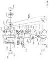
- FIG. 1is a drawing of a preferred embodiment of the invention.
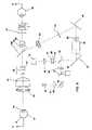
- FIG. 2is a drawing showing the optical layout of the retinal imaging portion of the preferred embodiment.
- FIG. 2Ais a drawing showing the grouping of the elements of FIG. 2 into an objective module, a relay module, and an imaging module.
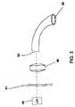
- FIG. 3is a drawing of a preferred ring light source.
- FIGS. 4 , 4 A, and 5are drawings showing the corneal imaging portion of the preferred embodiment.
- FIG. 1is shown the exterior design of a first preferred embodiment of the present invention.
- a typical headrest 1 and chin rest 2is provided to stabilize the patient head.
- the slit lamp 3provides illumination for examination of the cornea and is adjustable in brightness, color, and width of slit.
- the base 4provides the usual degrees of freedom in angular, transverse and longitudinal motion. Inside of the camera are means for adjusting the height of the camera potentially through a motorized system.
- Joystick 5assists in controlling motion and has control switches for operation of the system.
- the joystick 5is shown on base 4 .
- the joystick 5can be mounted on a portable base, and be placed on different position away from the base 4 .
- the retina 9is the back portion of the eye and is a curved object plane.
- the vitreous 11is a non-achromatic gel that fills the eye.
- one challenge of the optical systemwill be to image the curved plane of the retina through the non-achromatic gel onto the flat plane of the electronic area image sensor, typically CCD or CMOS, and produce high resolution achromatic images though an optical system which compensates for the non-achromaticity of the eye.
- the objective lensis comprised of lens elements 12 and 13 .
- the front lens 12is not changed between the retinal and corneal imaging and seals the optical system.
- the second objective element 13is internally changeable and provides for the optical system objective lens changes necessary for switching between the corneal and retinal imaging functions. This also places the lens changing mechanism inside the camera and out of contact with the operator's fingers for safety.
- the rear objective lens 13 when combined with the front objective lens 12comprises the objective lens set for retinal imaging.
- Plane 14is the location of the first real image and may contain a mask to limit the field of view.
- Mirror 15is switched into place for the retinal-imaging task, and when in place, blocks the view of the visualization section of the slit lamp/biomicroscope comprised of elements 35 through 37 and 7 . With the mirror in place the light is directed downwards and is further reflected by mirrors 16 and 17 and directed to image sensor 18 .
- Located at 19is an aperture that is the optical aperture for the imaging system. This aperture is relayed to the lens of the eye to form the entrance pupil of the camera when in the retinal imaging mode.
- Lens 20projects the image at 14 approximately at infinity and lens 21 is movable along the optical axis to focus the image exactly at infinity.
- Lens set 22can be inserted or removed to change the magnification of the system.
- lens 23refocuses the image onto the image sensor 18 .
- sensors of various size or formatcan be utilized by changing only one lens. This is a significant advantage as the sensor for color imaging may have a different size than one optimized for angiography, which might be a larger format sensor operating in a single color. It also allows the system to be retrofitted for new sensors as they may become available.
- Masks or programmable light sources such as LCD'scan be used at 27 to provide for vision function testing. Tests such as perimetry, color sensitivity, contrast sensitivity testing, and the like may be readily provided.
- Source 28provides illumination for retinal imaging and can be pulsed or continues.
- the source 28is shaped as a ring of light and the light is injected co-axially by lenses 29 and 30 such that a ring of light is projected onto the eye lens of the patient but outside of the entrance pupil.
- the illumination lightpasses through the space outside the mirror 17 .
- plane 31a small diameter disk shaped optical linear polarizer is placed on the optical axis to polarize, in the plane of the paper, the portion of the illuminating beam that is on axis. There is an unwanted reflection from objective lens 12 and 13 and this reflection will be polarized. The refection from the retina is however depolarizing.
- polarizing beam splitter 24reflects the s-polarized light and transmits the p-polarized light.
- the polarization direction of the linear polarizer at plane 31is oriented to be normal to that of p-polarization at beam splitter ( 24 ).
- an infrared imaging systemconsisting of beam sampler 32 , lens 33 , and infrared camera 34 is inserted into the optical path.
- the beam sampler 32is highly transmissive to the visual light and slightly reflective for infrared light.
- an infrared source(not shown in FIG. 2 ) mounted outside the periphery of lens 12
- infrared lightis collected by lens 12 and 13 , and then sampled by beam sampler 32 .
- Lens 33forms a corneal image on the camera 34 .
- the image formed on camera 34can be used to determine the transverse and longitudinal alignment to the eye.
- a light emitting diode (LED) module 42consists of multiple white color LEDs could be used to provide light for the source 28 .
- LEDlight emitting diode
- the lightis coupled into the entrance of fiber optical cable 39 by a lens 40 after passing through an optical filter 41 to properly adjust the color temperature of the light.
- the entrance of the fiber optical cable 39has a shape similar to that of LED matrix on module 42 .
- the exit of the fiber optical cable 39forms a ring, which becomes the light source 28 .
- the LED module 42can work in either pulsed or continuous mode. When working in pulsed mode, the light pules is synchronized with the trigger signals from the CCD camera.
- the change in the duration of the light puleswould adjust the brightness of the image, which is done automatically by the automatic exposure mechanism. Further compensation for the lighting condition can be adjusted manually if needed. If the light pulses are triggered consecutively by the imager, then a continuous illumination is perceived by the clinicians since the frequency of the pulses is higher than human eye can distinguish. When the interlaced CCD imager is used, the pulsed mode of illumination helps capture a single retinal picture to the computer with high speed and non-interlacing effect. Triggering a single light pulse synchronized with one of two fields for the captured image frame, and removing the light pulses before and immediately after that light pulse, will provide a full-frame image without the interlacing effect.
- the light puleWhen working in the pulsed mode, the light pule is synchronized with the trigger signals from the CCD camera. The change in the duration of the light pules would adjust the brightness of the image.
- the LED module 42can be moved out and replaced with the one consisting of multiple high power infrared or blue LEDs. These modules preferably provide light source for the FA and ICG sessions, and work in both continuous and pulsed mode similar to that of white color LED module. A blocking optical filter is inserted into the imaging path to block the excitation light.
- the electronically controlled actuators behind the mirror 15can tilt the mirror slightly along a axis within the paper plane, which in effect laterally moves the position of the optical aperture 19 and optical components from 20 to 23 and imager 18 .
- a trigger signal from the electronic image sensorflashes the light source 28 and the computer records a digital image.
- a second imageis taken.
- the amount of tiltmay be introduced to the mirror 16 in opposite direction to generate a more precise stereoscopic view.
- Laser 43 Ais guided to port 43 by an optical fiber 43 B and passes through one of the pinholes on the pinhole array 44 that has pinholes of various sizes. Additional optics may be introduced between the port 43 and pinhole array 44 to homogenize the laser intensity.
- Lens 45collimates the laser beam to lens 47 , which in turn focuses the laser to the plane 14 and subsequently to the retina 9 .
- the location of mirror 46is conjugate to the entrance pupil of the optical system that is located at the eye lens of the patient. Mirror 46 may be rotated in two orthogonal axes in order to steer the laser beam across the retina.
- a narrow band optical beam splitter ( 50 )is inserted into the optical system to inject the laser light into the optical system while allowing the visual light passing though to the image sensor from the retina.
- the beam splitter 50could also be a broad band polarization beam splitter, which reflects the s-polarized light only.
- the optical beam splitter 47samples a small amount of laser light onto photo sensor 48 to determine the power of the laser light. With help of the image sensor the irradiance of the laser on retina can be determined.
- the beam splitter 50is located between mirror 17 and aperture 19 .
- the beam splitter 50can actually placed anywhere along the optical axis between the mirror 17 and image plane 14 .
- the beam splitter 50may be located between lens 30 and mirror 17 or between light source 28 and lens 29 .
- the optical component 43 through 49may function similarly in these alternative options.
- the lasermay also be projected into the optical system from the space between light source 28 , which is shaped as a ring, and mirror 17 , which may be a dichroic beam splitter.
- the laser beamis injected in the middle of the illumination beam. Beam splitter 50 would be eliminated, but the optical components in the projection system from 44 through 49 would be kept.
- the image sensor 18 or other detectorsmay detect the motion of the retina.
- the retinal image and the laser spotthen can be stabilized by a servo system with two electrically activated actuators controlling the tilt of the mirror 16 and/or 17 .
- the laser spotmay track the retinal image by controlling the tilt of mirror 46 .
- the imaging systemcan be operated simultaneously. Thus, angiography can be performed simultaneous with treatment.
- FIGS. 4 and 5To describe this embodiment utilized for the corneal imaging reference is made to FIGS. 4 and 5 .
- FIG. 5is shown a horizontal cross sectional view of the corneal imaging system in a plane on the optical axis line that includes the cornea 10 .
- FIG. 4is shown a vertical cross sectional view of the corneal imaging system alone and through the middle of the system and in a plane which includes the cornea 10 .
- the optics which are used for retinal imagingonly have been moved out and replaced with those used for imaging and visualization of the anterior segment.
- the elements, which are changed between corneal and retinal imaging,include replacing mirror 15 with mirror 15 A, adding elements 53 , 55 , 56 , and 52 , and replacing lens 13 with lens 51 .
- Optical lens 12 and 51comprise the front and rear elements of the objective lens.
- Lens 12is sealed in place and lens 13 used for retinal imaging is moved out and replaced with lens 51 .
- Lens 12 and 51together form the objective lens for the corneal imaging optical system and provide a virtual image of the cornea at image plane 57 .
- the objective lens setprojects the object to infinity.
- the illumination of the corneawill be provided by the common means of a slit-lamp.
- Various lens sets 52are inserted through an internal mechanism into the optical system and can be changed for higher or lower magnification as required.
- the individual axes of lenses in lens sets 52are offset horizontally to the objective lens set to produce a stereo image.
- the lens sets 52are afocal and can be reversed in direction to produce two magnifications for each lens set.
- the objective lens setredirects the individual optical axis of lens set 51 to converge at the center of the eye. By this means the corneal imaging system provides the proper look angle for stereoscopic vision.
- a mirror 15that can be moved into the beam to direct the rays exiting the objective lens and magnification adjustment downwards to the digital imaging system located vertically below or removed to allow visualization of the cornea.
- the reflective coating on this mirroris designed to be highly reflective to laser light, but partially transmissive to the light of other wavelengths. In fact, this mirror can be a partial reflector to provide simultaneous visual observation with digital imaging and imaging simultaneous with laser treatment if desired.
- common erection prisms 36follows image relay lens 35 , as shown in FIG. 5 .
- An inverted real imageis formed at location 37 .
- Lens sets 7are common oculars or eyepieces and an erect image is formed at the retina of the user's eyes 38 .
- the optical axes of the two ocular pathsare shown to be in parallel in FIG. 5 . However, the axes can be tilted to converge.
- lens set 52By changing lens set 52 a variety of magnifications are readily achieved and the eyepiece lens 7 can be exchanged as well for a wide range of magnifications.
- the corneal imaging systemWhen the corneal imaging system is to be used for digital imaging at least some of the light is reflected downwards by mirror 15 .
- the light raysare relayed by lens 53 and 56 to form a virtual image of the cornea at plane 57 . This is the same location for the image as produced by the retinal imaging system.
- This virtual imagethen can be projected to the image sensor 18 by the lens 20 , 21 and 23 .
- Lens 20projects the image to infinity and lens 21 will make small adjustments to this and therefore accomplishes focusing.
- Lens 23focuses the light onto the electronic camera 18 .
- Lens 53 and 56are aligned to the optical axis of a single lens set 52 that is offset from the axis of lens 12 and 51 and image sensor 18 .
- Prism set 55is then used to translate the axis of the light beam from the offset axis to the centrally located axis of the CCD imaging system.
- the relay lens 53 and 56not only form a real corneal image at plane 54 , but also an entrance pupil of the imaging system at the front of lens set 52 . This entrance pupil coincides with the one formed in the visualization system.
- the image from the other viewing channelcan be recorded.
- a stereoscopic view of anterior segment of eyeis created.
- the stereoscopic effectis identical to that seen by naked eye from the binocular directly.
- Another stereoscopic approachwould be to align the relay lens 53 and 56 to the centrally located axis of the CCD image system and eliminate the prism set 55 .
- Electronically controlled actuators behind the mirror 15could then tilt the mirror slightly along an axis within the paper plane which in effect moves the image position laterally and the optical aperture 19 and electronic imaging system behind it.
- Two images, taken from two oppositely tilted mirror positions,are recorded to and displayed by the computer to create the stereoscopic effect.
- the second approachintroduces a tilt between the two viewing channels in the digital recording.
- the stereoscopic effectmay be slightly different from that of the first approach.
- a third approachwould tilt the mirror 16 in opposite direction from the tilt of mirror 15 to cancel out the unwanted effect.
- the result stereoscopic effectwould be similar to that of the first approach.
- a laser projection system identical with that used for the retinal laser systemis formed by optical components 43 through 49 and projects laser to the cornea.
- the laser spotmay either monitored from the image sensor alone or from both CCD camera and binoculars.
- a slit lamp or other well-known meansprovides illumination of the eye.
- An LED moduleconsists of multiple white LEDs can be used as the light source for the slit lamp.
- the light sourceworks in either continuous or pulsed mode. When it works in pulsed mode, the light pulse is synchronized with the trigger signals from the CCD imager. A continuous illumination is then perceived by the clinicians since the frequency of the pulses is higher than human eye can distinguish.
- the brightness of the corneal image, observed either through the binocular or the CCD imageris adjustable by changing the duration of the light pulse.
- the pulsed mode of illuminationhelps capturing a single corneal picture to the computer with high speed and non-interlacing effect. Triggering a single light pulse synchronized with one of two fields for the captured image frame, and removing the light pulses before and immediately after that light pulse does it.
- the corneais a slightly positively curved plane and the image path is air.
- the retinais a highly negatively curved plane and part of the optical path is the vitreous. This fluid is non-achromatic so the camera must compensate for the non-achromaticity of the media for the retina but not so for the air path for the cornea.
- the present inventionachieves both of these functions, and at the high resolution required for ophthalmology as well as providing multiple magnifications.
- the systemis designed to image the retina with low dilation.
- the first design criteriais to inject the light into the eye through a small ring about the entrance pupil and aligning this to the iris opening. Achieving this provides uniform illumination to the retina and a high contrast image.
- transverse and longitudinal alignmentsare critical.
- the use of an infrared camera operating at wavelengths that the eye cannot seeis crucial.
- the infrared illuminationdoes not cause the pupil to constrict.
- the IR camerais always on and focused on the cornea even while the retinal image is being obtained and a separate display shows this image. By this means the transverse and longitudinal alignment of the camera is always assured.
- the optical systemOf further great challenge for the optical system is the requirement to have different camera entrance pupil locations for the corneal and retinal imaging functions.
- For imaging the retinait is of significant advantage to place the entrance pupil of the camera at the eye lens. This reduces the effect of the aberrations of the eye and improves image contrast.
- the entrance pupilmust lie at the objective lens of the imaging system. The system thus operates as a “microscope” when imaging the cornea and as a “telescope” when imaging the retina.
- the systemprovides a plane in the instrument that is conjugate to the retina and this plane lies on the surface of the electronic image sensor. With certain optical beam splitters, this plane can be made accessible within the instrument at other locations for other uses. It is recognized that light emerging from the retina will return to and be in focus on this conjugate plane and this is the modality for imaging. However, light exiting from a plane conjugate to the retina and directed towards the eye will be projected onto the retina. Thus, we have within the system the ability to project light patterns onto the retina. The system could be used for testing the performance of the eye as an imaging system. A simple example of this would be to project visual acuity charts or color perception information. A more complex application would be to perform perimetric measurements. In fact, a programmable LCD could be used to modify the stimulus.
- White color LED modulesconsist of multiple LEDs will be used as the light sources in both retinal imaging and corneal imaging part of the system.
- the LED moduleworks either continuously or in pulsed mode. It will replace the CW light source (often halogen lamp) and flash source (often Xenon lamp) with one single source. It consumes less power, generates less heat, use less housing space, and last much longer. LED modules with different wavelengths will be used as light source for FA and ICG angiograms.
- the stereoscopic images of optic nerve headhave shown great clinic values in assessing the progress of diseases like glaucoma.
- the proposed systemcan take two digital images of optic nerve head from two different entrance pupil positions automatically in less than 1/10 of second. When the two images are displayed separately into left and right eyes, the clinician then sees and perceives the stereoscopic views of the optic nerve head.
- the stereoscopic corneal imagescan also be taken and displayed digitally.
- the proposed systemcan also take two digital images of anterior segment of the eye automatically in very short time, display stereoscopic view digitally.
- the proposed systemprovides an internally integrated laser projection system.
- the laser lightcan be projected internally from a plane conjugate to the imaging plane. No external optics or attachment is needed. The hand of clinician is free from holding the laser lens. There will be no more scattering of laser light from external optics.
- the alignmentis easy and simple.
- the retinal imageis much clearer.
- the laserwould be delivered to the corneal region.
- the operatorcan observe the retinal/corneal image with aiming laser spot on them, then designate (on the image as presented by the computer) the areas to be treated.
- the systemunder computer control, could apply the laser treatment. In the instance of some laser treatments, over 1,000 spots are applied. Performing this manually is very slow but performing it under computer control could be accomplished quickly and accurately. Further, tracking systems could be used to further stabilize the image and/or the laser beam location. The location and accumulated energy delivery as a function of location can be determined and monitored, which is important parameter in some therapies.
- the clinicianis free from the restricted posture during the treatment session, which is the case in the current slit-lamp delivery system. It would greatly reduce the stress imposed on the patients and clinicians.
- this systemcan perform the popular flourescein and indocyanine green angiographies. Even the stereo angiograms can be recorded and displayed digitally.
- the systemis equipped to utilize the differing format sensors that may be preferred for color or monochrome imaging.
- the angiographic imagescan be displayed with known scales to help determining the position and size of laser treatment areas. During the treatment, the angiographic images can be displayed side-by-side with the live images of same scale on one computer monitor. It will greatly reduce the time and preparation work before a laser treatment. Laser treatments can be accomplished simultaneously with angiography. This gives the clinician the ability to identify the area for treatment and monitor in real time the effect of the laser treatment.
- digital imagingobviously eliminates the delay and cost of film processing and assessment of image quality is immediately available.
- studieshave shown that in screening for diabetic retinopathy, a better result is obtained by examining images rather than the direct visualization.
- digital imagingbrings other substantial advantages.
- One of the most prominentis the ability to share findings with colleges and the like by digital transference means. That is, the actual clinical data may be obtained at one location and sent to another by electronic means for remote assessment. If one could examine the entire eye by digital means, a clinical assistant at a remote site could obtain the “digital copy” of the eye and transfer it to the appropriate clinical expert for review.
- Such a systemwould clearly need to image both the posterior and anterior segments of the eye and with high quality images.
Landscapes
- Health & Medical Sciences (AREA)
- Life Sciences & Earth Sciences (AREA)
- Ophthalmology & Optometry (AREA)
- General Health & Medical Sciences (AREA)
- Surgery (AREA)
- Engineering & Computer Science (AREA)
- Biomedical Technology (AREA)
- Heart & Thoracic Surgery (AREA)
- Veterinary Medicine (AREA)
- Public Health (AREA)
- Physics & Mathematics (AREA)
- Animal Behavior & Ethology (AREA)
- Biophysics (AREA)
- Molecular Biology (AREA)
- Medical Informatics (AREA)
- Optics & Photonics (AREA)
- Nuclear Medicine, Radiotherapy & Molecular Imaging (AREA)
- Vascular Medicine (AREA)
- Eye Examination Apparatus (AREA)
Abstract
Description
Claims (35)
Priority Applications (3)
| Application Number | Priority Date | Filing Date | Title |
|---|---|---|---|
| US11/158,426US7121665B2 (en) | 2000-06-13 | 2005-06-22 | Digital eye camera |
| US11/581,020US7922327B2 (en) | 2000-06-13 | 2006-10-13 | Apparatus and method for illuminating and viewing the anterior segment of an eye of a patient |
| US13/047,722US8454161B2 (en) | 2000-06-13 | 2011-03-14 | Apparatus and method for illuminating and imaging the retina of an eye of a patient |
Applications Claiming Priority (4)
| Application Number | Priority Date | Filing Date | Title |
|---|---|---|---|
| US09/592,899US6361167B1 (en) | 2000-06-13 | 2000-06-13 | Digital eye camera |
| US10/033,432US6685317B2 (en) | 2000-06-13 | 2001-12-26 | Digital eye camera |
| US10/758,695US6921169B2 (en) | 2000-06-13 | 2004-01-15 | Digital eye camera |
| US11/158,426US7121665B2 (en) | 2000-06-13 | 2005-06-22 | Digital eye camera |
Related Parent Applications (1)
| Application Number | Title | Priority Date | Filing Date |
|---|---|---|---|
| US10/758,695DivisionUS6921169B2 (en) | 2000-06-13 | 2004-01-15 | Digital eye camera |
Related Child Applications (1)
| Application Number | Title | Priority Date | Filing Date |
|---|---|---|---|
| US11/581,020ContinuationUS7922327B2 (en) | 2000-06-13 | 2006-10-13 | Apparatus and method for illuminating and viewing the anterior segment of an eye of a patient |
Publications (2)
| Publication Number | Publication Date |
|---|---|
| US20050237486A1 US20050237486A1 (en) | 2005-10-27 |
| US7121665B2true US7121665B2 (en) | 2006-10-17 |
Family
ID=21870353
Family Applications (5)
| Application Number | Title | Priority Date | Filing Date |
|---|---|---|---|
| US10/033,432Expired - LifetimeUS6685317B2 (en) | 2000-06-13 | 2001-12-26 | Digital eye camera |
| US10/758,695Expired - LifetimeUS6921169B2 (en) | 2000-06-13 | 2004-01-15 | Digital eye camera |
| US11/158,426Expired - Fee RelatedUS7121665B2 (en) | 2000-06-13 | 2005-06-22 | Digital eye camera |
| US11/581,020Expired - Fee RelatedUS7922327B2 (en) | 2000-06-13 | 2006-10-13 | Apparatus and method for illuminating and viewing the anterior segment of an eye of a patient |
| US13/047,722Expired - Fee RelatedUS8454161B2 (en) | 2000-06-13 | 2011-03-14 | Apparatus and method for illuminating and imaging the retina of an eye of a patient |
Family Applications Before (2)
| Application Number | Title | Priority Date | Filing Date |
|---|---|---|---|
| US10/033,432Expired - LifetimeUS6685317B2 (en) | 2000-06-13 | 2001-12-26 | Digital eye camera |
| US10/758,695Expired - LifetimeUS6921169B2 (en) | 2000-06-13 | 2004-01-15 | Digital eye camera |
Family Applications After (2)
| Application Number | Title | Priority Date | Filing Date |
|---|---|---|---|
| US11/581,020Expired - Fee RelatedUS7922327B2 (en) | 2000-06-13 | 2006-10-13 | Apparatus and method for illuminating and viewing the anterior segment of an eye of a patient |
| US13/047,722Expired - Fee RelatedUS8454161B2 (en) | 2000-06-13 | 2011-03-14 | Apparatus and method for illuminating and imaging the retina of an eye of a patient |
Country Status (3)
| Country | Link |
|---|---|
| US (5) | US6685317B2 (en) |
| AU (1) | AU2002359836A1 (en) |
| WO (1) | WO2003057024A1 (en) |
Cited By (3)
| Publication number | Priority date | Publication date | Assignee | Title |
|---|---|---|---|---|
| US20080309876A1 (en)* | 2007-06-15 | 2008-12-18 | Massie Norbert A | Method And Apparatus For Imaging An Eye Of A Small Animal |
| US20100134759A1 (en)* | 2008-06-26 | 2010-06-03 | Silvestrini Thomas A | Digital imaging system for eye procedures |
| US10973683B2 (en)* | 2017-01-31 | 2021-04-13 | Amo Development, Llc | Methods and systems for laser ophthalmic surgery that provide for iris exposures below a predetermined exposure limit |
Families Citing this family (147)
| Publication number | Priority date | Publication date | Assignee | Title |
|---|---|---|---|---|
| DE10001131A1 (en)* | 2000-01-13 | 2001-07-19 | Wavelight Laser Technologie Ag | Device for ophthalmic eye treatment with fixation light beam |
| US6685317B2 (en) | 2000-06-13 | 2004-02-03 | Massie Research Laboratories, Inc. | Digital eye camera |
| JP2003047595A (en)* | 2001-08-06 | 2003-02-18 | Nidek Co Ltd | Ophthalmic imaging system |
| US20050117118A1 (en)* | 2001-10-05 | 2005-06-02 | David Miller | Digital ophthalmic workstation |
| US20030071893A1 (en)* | 2001-10-05 | 2003-04-17 | David Miller | System and method of providing visual documentation during surgery |
| DE10221472B4 (en)* | 2002-05-15 | 2004-07-08 | E-Eyecare Gmbh | diagnostic device |
| US7145571B2 (en)* | 2002-11-01 | 2006-12-05 | Tenebraex Corporation | Technique for enabling color blind persons to distinguish between various colors |
| US20110229023A1 (en)* | 2002-11-01 | 2011-09-22 | Tenebraex Corporation | Technique for enabling color blind persons to distinguish between various colors |
| US7916152B2 (en)* | 2002-11-01 | 2011-03-29 | Tenebraex Corporaton | Technique for enabling color blind persons to distinguish between various colors |
| DE10254369A1 (en)* | 2002-11-21 | 2004-06-03 | Carl Zeiss Meditec Ag | Ophthalmic device with eye tracker unit |
| DE10302401A1 (en)* | 2003-01-21 | 2004-07-29 | Leica Microsystems (Schweiz) Ag | surgical microscope |
| CA2476457A1 (en)* | 2003-08-22 | 2005-02-22 | Mario Fabris | Method and apparatus for alignment equipment in a steel mill |
| JP4492845B2 (en)* | 2003-10-14 | 2010-06-30 | 株式会社ニデック | Laser treatment device |
| JP4233439B2 (en)* | 2003-11-28 | 2009-03-04 | 株式会社ニデック | Ophthalmic equipment |
| WO2005065528A1 (en)* | 2004-01-02 | 2005-07-21 | Vision Instruments Pty Ltd | Devices to facilitate alignment and focussing of a fundus camera |
| FR2865369A1 (en)* | 2004-01-22 | 2005-07-29 | Centre Nat Rech Scient | DEVICE AND METHOD FOR COMPENSATING CORNEAL BIREFRINGENCE IN AN OPTICAL EXAMINATION OF EYE PARTS SITUATED OUTSIDE THE CORNEA, AND EYE EXAMINATION SYSTEM INCLUDING SUCH A DEVICE |
| US20050231688A1 (en)* | 2004-04-01 | 2005-10-20 | Jones Peter W J | Retinal screening using a night vision device |
| JP4509668B2 (en)* | 2004-06-25 | 2010-07-21 | 株式会社トプコン | Fundus photography system |
| US8109635B2 (en)* | 2004-08-12 | 2012-02-07 | Ophthalmic Imaging Systems | Integrated retinal imager and method |
| ATE534356T1 (en)* | 2005-02-01 | 2011-12-15 | Kurt Heiberger | DEVICE FOR MEASURING AND SURGICALLY CORRECTING IMAGINATION DEFECTS IN THE HUMAN EYE |
| WO2007012008A2 (en)* | 2005-07-15 | 2007-01-25 | California Institute Of Technology | Optomechanical and digital ocular sensor reader systems |
| JP2007029726A (en)* | 2005-07-22 | 2007-02-08 | Carl Zeiss Meditec Ag | Ring light fundus camera |
| WO2007018532A1 (en)* | 2005-08-03 | 2007-02-15 | Boston Scientific Scimed, Inc. | Systems, devices and methods relating to a shape resilient sling-like support for treating urinary incontinence |
| US7445335B2 (en)* | 2006-01-20 | 2008-11-04 | Clarity Medical Systems, Inc. | Sequential wavefront sensor |
| US8919958B2 (en) | 2006-01-20 | 2014-12-30 | Clarity Medical Systems, Inc. | Apparatus and method for operating a real time large diopter range sequential wavefront sensor |
| US9101292B2 (en) | 2006-01-20 | 2015-08-11 | Clarity Medical Systems, Inc. | Apparatus and method for operating a real time large dipoter range sequential wavefront sensor |
| US8777413B2 (en) | 2006-01-20 | 2014-07-15 | Clarity Medical Systems, Inc. | Ophthalmic wavefront sensor operating in parallel sampling and lock-in detection mode |
| US8356900B2 (en) | 2006-01-20 | 2013-01-22 | Clarity Medical Systems, Inc. | Large diopter range real time sequential wavefront sensor |
| US8100530B2 (en)* | 2006-01-20 | 2012-01-24 | Clarity Medical Systems, Inc. | Optimizing vision correction procedures |
| US8820929B2 (en) | 2006-01-20 | 2014-09-02 | Clarity Medical Systems, Inc. | Real-time measurement/display/record/playback of wavefront data for use in vision correction procedures |
| EP2762972B1 (en)* | 2006-02-13 | 2020-04-08 | Midmark Corporation | Monocular three-dimensional imaging |
| US7372642B2 (en)* | 2006-02-13 | 2008-05-13 | 3M Innovative Properties Company | Three-channel camera systems with non-collinear apertures |
| US7646550B2 (en)* | 2006-02-13 | 2010-01-12 | 3M Innovative Properties Company | Three-channel camera systems with collinear apertures |
| US7819591B2 (en) | 2006-02-13 | 2010-10-26 | 3M Innovative Properties Company | Monocular three-dimensional imaging |
| USD582556S1 (en)* | 2006-05-02 | 2008-12-09 | Kabushiki Kaisha Topcon | Fundus camera |
| EP1857043A3 (en)* | 2006-05-18 | 2007-12-12 | Rhine-tec Gesellschaft für Virtuelle Instrumentierung mbH | Device for contactless examination of the eye |
| EP1867273A1 (en)* | 2006-06-12 | 2007-12-19 | Opto Electrônica S/A | System for obtaining a fundus image |
| US20080004610A1 (en)* | 2006-06-30 | 2008-01-03 | David Miller | System for calculating IOL power |
| US7553020B2 (en)* | 2006-09-29 | 2009-06-30 | Welch Allyn, Inc. | Medical diagnostic instrument with variable focus liquid lens |
| JP4907287B2 (en)* | 2006-09-29 | 2012-03-28 | 株式会社ニデック | Slit lamp microscope and ophthalmic laser treatment apparatus having the same |
| WO2008043469A1 (en)* | 2006-10-06 | 2008-04-17 | Carl Zeiss Microlmaging Gmbh | Method for controlling the power of a laser diode or led |
| US7621638B2 (en) | 2006-11-29 | 2009-11-24 | Clarity Medical Systems, Inc. | Delivering a short Arc lamp light for eye imaging |
| IL182158A0 (en)* | 2007-03-25 | 2007-07-24 | David Wexelman | Using a web camera on a pc for diagnosis and treatment of mental disorders |
| DE102007035850A1 (en)* | 2007-07-31 | 2009-02-05 | Carl Zeiss Meditec Ag | laser system |
| US11839430B2 (en) | 2008-03-27 | 2023-12-12 | Doheny Eye Institute | Optical coherence tomography-based ophthalmic testing methods, devices and systems |
| US8348429B2 (en)* | 2008-03-27 | 2013-01-08 | Doheny Eye Institute | Optical coherence tomography device, method, and system |
| WO2009120543A1 (en)* | 2008-03-27 | 2009-10-01 | Doheny Eye Institute | Optical coherence tomography device, method, and system |
| US9168173B2 (en) | 2008-04-04 | 2015-10-27 | Truevision Systems, Inc. | Apparatus and methods for performing enhanced visually directed procedures under low ambient light conditions |
| EP3884844A1 (en) | 2008-07-18 | 2021-09-29 | Doheny Eye Institute | Optical coherence tomography-based ophthalmic testing methods, devices and systems |
| JP5389390B2 (en)* | 2008-07-25 | 2014-01-15 | オリンパス株式会社 | Observation device |
| US10117721B2 (en)* | 2008-10-10 | 2018-11-06 | Truevision Systems, Inc. | Real-time surgical reference guides and methods for surgical applications |
| US9226798B2 (en)* | 2008-10-10 | 2016-01-05 | Truevision Systems, Inc. | Real-time surgical reference indicium apparatus and methods for surgical applications |
| US20100245765A1 (en)* | 2008-10-28 | 2010-09-30 | Dyer Holdings, Llc | Video infrared ophthalmoscope |
| US8433117B2 (en)* | 2008-11-21 | 2013-04-30 | The United States Of America As Represented By The Secretary Of The Army | Computer controlled system for laser energy delivery to the retina |
| US9173717B2 (en) | 2009-02-20 | 2015-11-03 | Truevision Systems, Inc. | Real-time surgical reference indicium apparatus and methods for intraocular lens implantation |
| AU2009343635B2 (en)* | 2009-04-01 | 2014-12-11 | Centervue S.P.A | Instrument for eye examination |
| US8262221B2 (en)* | 2009-04-24 | 2012-09-11 | Filar Paul A | Ophthalmological diagnostic system |
| US8784443B2 (en) | 2009-10-20 | 2014-07-22 | Truevision Systems, Inc. | Real-time surgical reference indicium apparatus and methods for astigmatism correction |
| US20110103655A1 (en)* | 2009-11-03 | 2011-05-05 | Young Warren G | Fundus information processing apparatus and fundus information processing method |
| US20110213342A1 (en)* | 2010-02-26 | 2011-09-01 | Ashok Burton Tripathi | Real-time Virtual Indicium Apparatus and Methods for Guiding an Implant into an Eye |
| CN103025282B (en) | 2010-05-10 | 2015-03-11 | 特拉维夫大学拉玛特有限公司 | System for treating glaucoma by directing electromagnetic energy to the limbal area of an eye |
| US9579153B2 (en)* | 2010-06-03 | 2017-02-28 | Carl Zeiss Meditec Ag | Device and method for vitreous humor surgery |
| JP2012034925A (en)* | 2010-08-10 | 2012-02-23 | Topcon Corp | Ophthalmologic imaging device |
| ES2380469B2 (en)* | 2010-10-15 | 2013-04-10 | Universidad De Murcia | INSTRUMENT FOR THE QUICK MEASURE OF THE OPTICAL PROPERTIES OF THE EYE IN THE VISUAL FIELD. |
| EP2630543B1 (en) | 2010-10-18 | 2019-10-09 | Reach3D Medical LLC. | A STEREOSCOPIC OPTIC Adapter |
| US9635347B2 (en) | 2010-11-15 | 2017-04-25 | Reach3D Medical Llc | Stereoscopic relay optics |
| US9301683B2 (en)* | 2010-12-13 | 2016-04-05 | University Of Virginia Patent Foundation | Intuitive techniques and apparatus for ophthalmic imaging |
| USD701317S1 (en)* | 2011-02-25 | 2014-03-18 | Kowa Company, Ltd. | Retinal camera |
| WO2012119633A1 (en)* | 2011-03-04 | 2012-09-13 | Eyesight & Vision Gmbh | Projector device, and medical device comprising the projector device |
| USD705430S1 (en)* | 2011-03-24 | 2014-05-20 | Canon Kabushiki Kaisha | Corneal tomography apparatus |
| DE102011075799A1 (en)* | 2011-05-13 | 2012-11-15 | Carl Zeiss Meditec Ag | Optical system for a laser therapy device |
| USD698444S1 (en)* | 2011-08-09 | 2014-01-28 | I-Optics | Scanning laser opthalmoscope |
| US8992042B2 (en) | 2011-11-14 | 2015-03-31 | Halma Holdings, Inc. | Illumination devices using natural light LEDs |
| WO2013081619A1 (en)* | 2011-12-01 | 2013-06-06 | University Of Miami | System for ophthalmic imaging |
| EP3597100B1 (en) | 2011-12-05 | 2024-10-23 | Leica Microsystems NC, Inc. | Optical imaging systems having input beam shape control and path length control |
| US9655517B2 (en) | 2012-02-02 | 2017-05-23 | Visunex Medical Systems Co. Ltd. | Portable eye imaging apparatus |
| US20150021228A1 (en) | 2012-02-02 | 2015-01-22 | Visunex Medical Systems Co., Ltd. | Eye imaging apparatus and systems |
| US9179840B2 (en) | 2012-03-17 | 2015-11-10 | Visunex Medical Systems Co. Ltd. | Imaging and lighting optics of a contact eye camera |
| US9351639B2 (en) | 2012-03-17 | 2016-05-31 | Visunex Medical Systems Co. Ltd. | Eye imaging apparatus with a wide field of view and related methods |
| US8777412B2 (en)* | 2012-04-05 | 2014-07-15 | Bioptigen, Inc. | Surgical microscopes using optical coherence tomography and related methods |
| JP5989523B2 (en) | 2012-05-01 | 2016-09-07 | 株式会社トプコン | Ophthalmic equipment |
| CN102657516B (en)* | 2012-05-10 | 2014-05-28 | 中国科学院长春光学精密机械与物理研究所 | Automatic retina imaging system |
| US11077318B2 (en) | 2012-05-25 | 2021-08-03 | Ojai Retinal Technology, Llc | System and process of utilizing energy for treating biological tissue |
| US10076671B2 (en) | 2012-05-25 | 2018-09-18 | Ojai Retinal Technology, Llc | Apparatus for retina phototherapy |
| US10894169B2 (en) | 2012-05-25 | 2021-01-19 | Ojai Retinal Technology, Llc | System and method for preventing or treating Alzheimer's and other neurodegenerative diseases |
| US10278863B2 (en) | 2016-03-21 | 2019-05-07 | Ojai Retinal Technology, Llc | System and process for treatment of myopia |
| US10596389B2 (en) | 2012-05-25 | 2020-03-24 | Ojai Retinal Technology, Llc | Process and system for utilizing energy to treat biological tissue |
| US10953241B2 (en) | 2012-05-25 | 2021-03-23 | Ojai Retinal Technology, Llc | Process for providing protective therapy for biological tissues or fluids |
| US9381115B2 (en) | 2012-05-25 | 2016-07-05 | Ojai Retinal Technology, Llc | System and process for retina phototherapy |
| US9381116B2 (en) | 2012-05-25 | 2016-07-05 | Ojai Retinal Technology, Llc | Subthreshold micropulse laser prophylactic treatment for chronic progressive retinal diseases |
| US20140330352A1 (en)* | 2012-05-25 | 2014-11-06 | Ojai Retinal Technology, Llc | Apparatus for retina phototherapy |
| US9962291B2 (en) | 2012-05-25 | 2018-05-08 | Ojai Retinal Technology, Llc | System and process for neuroprotective therapy for glaucoma |
| US10874873B2 (en) | 2012-05-25 | 2020-12-29 | Ojai Retinal Technology, Llc | Process utilizing pulsed energy to heat treat biological tissue |
| US10219947B2 (en) | 2012-05-25 | 2019-03-05 | Ojai Retinal Technology, Llc | System and process for retina phototherapy |
| TW201406343A (en)* | 2012-08-01 | 2014-02-16 | Altek Corp | Image capture device for fundus and imaging methods thereof |
| WO2014036499A1 (en) | 2012-08-30 | 2014-03-06 | Truevision Systems, Inc. | Imaging system and methods displaying a fused multidimensional reconstructed image |
| ES2799154T3 (en) | 2013-02-26 | 2020-12-15 | Belkin Laser Ltd | Glaucoma treatment system |
| USD717856S1 (en) | 2013-03-01 | 2014-11-18 | Welch Allyn, Inc. | Optical device adapter |
| US10772497B2 (en) | 2014-09-12 | 2020-09-15 | Envision Diagnostics, Inc. | Medical interfaces and other medical devices, systems, and methods for performing eye exams |
| US9226856B2 (en) | 2013-03-14 | 2016-01-05 | Envision Diagnostics, Inc. | Inflatable medical interfaces and other medical devices, systems, and methods |
| WO2014197553A2 (en) | 2013-06-04 | 2014-12-11 | Bioptigen, Inc. | Hybrid telescope for optical beam delivery and related systems and methods |
| CN105592829B (en) | 2013-07-29 | 2018-11-16 | 拜尔普泰戈恩公司 | Surgical optical coherence tomography (OCT) and its related system and method for surgical operation |
| EP3039474A1 (en) | 2013-08-28 | 2016-07-06 | Bioptigen, Inc. | Heads up displays for optical coherence tomography integrated surgical microscopes |
| EP3110306B1 (en)* | 2014-02-20 | 2021-04-21 | Ingeneus Pty Ltd | Ophthalmic device, method and system |
| US20150342465A1 (en)* | 2014-05-27 | 2015-12-03 | United Integrated Services Co., Ltd. | Method of determining temperature shifting error derived from radiation sensor, method of measuring ocular surface temperature and apparatus thereof |
| US9986908B2 (en) | 2014-06-23 | 2018-06-05 | Visunex Medical Systems Co. Ltd. | Mechanical features of an eye imaging apparatus |
| WO2016010627A1 (en)* | 2014-07-16 | 2016-01-21 | Ojai Retinal Technology, Llc | Apparatus for retina phototherapy |
| US10314486B2 (en)* | 2014-08-08 | 2019-06-11 | The Johns Hopkins University | Head-mounted indirect opthalmoscope camera |
| JP1529228S (en)* | 2014-10-30 | 2015-07-21 | ||
| CN107708524A (en) | 2015-01-26 | 2018-02-16 | 威盛纳斯医疗系统公司 | Disposable separation sleeve for eye imaging devices and associated method |
| EP3253276B1 (en) | 2015-02-05 | 2025-08-13 | Carl Zeiss Meditec AG | A method and apparatus for reducing scattered light in broad-line fundus imaging |
| JP6657591B2 (en)* | 2015-05-01 | 2020-03-04 | 株式会社ニデック | Ophthalmic laser delivery and ophthalmic laser treatment device |
| US10022043B2 (en)* | 2015-06-24 | 2018-07-17 | Haixin Xue | Shortened slit lamp microscope |
| US20180303335A1 (en)* | 2015-06-24 | 2018-10-25 | Haixin Xue | Shortened Slit Lamp Microscope |
| EP3349642B1 (en) | 2015-09-17 | 2020-10-21 | Envision Diagnostics, Inc. | Medical interfaces and other medical devices, systems, and methods for performing eye exams |
| USD800314S1 (en)* | 2015-11-26 | 2017-10-17 | Crewt Medical Systems, Inc. | Eye testing apparatus and equipment |
| US9872616B2 (en) | 2015-12-03 | 2018-01-23 | Ehsan Daneshi Kohan | Pupillary response and eye anterior assessment |
| US10048696B2 (en)* | 2015-12-22 | 2018-08-14 | Uber Technologies, Inc. | Intelligent lens masking system for an autonomous vehicle |
| US9827066B2 (en)* | 2016-02-16 | 2017-11-28 | Novartis Ag | Methods and systems for pulsed illumination |
| US10709608B2 (en) | 2016-03-21 | 2020-07-14 | Ojai Retinal Technology, Llc | System and process for prevention of myopia |
| EP3448234A4 (en) | 2016-04-30 | 2019-05-01 | Envision Diagnostics, Inc. | MEDICAL DEVICES, SYSTEMS AND METHODS FOR OPERATING OCULAR EXAMINATIONS AND OCULOMETRY |
| DE102017105580B4 (en)* | 2016-11-04 | 2025-10-02 | Carl Zeiss Meditec Ag | Surgical microscope |
| DE102017103721B4 (en)* | 2017-02-23 | 2022-07-21 | Karl Storz Se & Co. Kg | Device for capturing a stereo image with a rotatable viewing device |
| US11083537B2 (en) | 2017-04-24 | 2021-08-10 | Alcon Inc. | Stereoscopic camera with fluorescence visualization |
| US10299880B2 (en) | 2017-04-24 | 2019-05-28 | Truevision Systems, Inc. | Stereoscopic visualization camera and platform |
| US10917543B2 (en) | 2017-04-24 | 2021-02-09 | Alcon Inc. | Stereoscopic visualization camera and integrated robotics platform |
| US11679031B2 (en)* | 2017-08-17 | 2023-06-20 | Lutronic Vision Inc. | Fundus alignment in optical treatment systems |
| CN107997739B (en)* | 2017-12-07 | 2020-08-21 | 魏征 | Neurology pupil light reflection diagnosis device and use method thereof |
| CN108371540A (en)* | 2018-01-22 | 2018-08-07 | 深圳盛达同泽科技有限公司 | Retina digital imaging system and retina digital imaging instrument |
| JP7321678B2 (en)* | 2018-06-13 | 2023-08-07 | 株式会社トプコン | slit lamp microscope and ophthalmic system |
| IL308110A (en) | 2018-07-02 | 2023-12-01 | Belkin Vision Ltd | Direct selective laser trabeculoplasty |
| US11202567B2 (en)* | 2018-07-16 | 2021-12-21 | Verily Life Sciences Llc | Retinal camera with light baffle and dynamic illuminator for expanding eyebox |
| JP7448973B2 (en) | 2018-10-28 | 2024-03-13 | ベルキン ヴィジョン リミテッド | Direct selective laser trabeculoplasty protection |
| USD922583S1 (en)* | 2018-11-09 | 2021-06-15 | Nikon Corporation | Fundus camera |
| US11642072B2 (en)* | 2019-02-07 | 2023-05-09 | The University Of Toledo | Telestroke eye examination accessory |
| CN110123267B (en)* | 2019-03-22 | 2022-02-08 | 重庆康华瑞明科技股份有限公司 | Additional floodlight projection device based on ophthalmic slit lamp and image analysis system |
| SG11202112758VA (en) | 2019-07-31 | 2021-12-30 | Xenon Vr Inc | Ophthalmologic testing systems and methods |
| CN110477855A (en)* | 2019-08-29 | 2019-11-22 | 合肥奥比斯科技有限公司 | A kind of binocular stereo vision fundus camera |
| WO2022018525A1 (en) | 2020-07-19 | 2022-01-27 | Belkin Vision Ltd. | Automated capsulotomy |
| EP4294252A1 (en)* | 2021-03-22 | 2023-12-27 | The Medical College of Wisconsin, Inc. | Laser-speckle contrast imaging system and method |
| US12048485B2 (en)* | 2021-04-05 | 2024-07-30 | Raytrx, Llc | Surgery 3D visualization apparatus |
| USD1005288S1 (en) | 2022-03-03 | 2023-11-21 | Xenon Ophthalmics Inc. | Module for head mounted display |
| USD1019641S1 (en) | 2022-03-03 | 2024-03-26 | Xenon Ophthalmics Inc. | Headset |
| USD1021898S1 (en) | 2022-03-03 | 2024-04-09 | Xenon Ophthalmics Inc. | Module for head mounted display |
| USD1005289S1 (en) | 2022-03-03 | 2023-11-21 | Xenon Ophthalmics Inc. | Headset |
| WO2024006808A2 (en)* | 2022-07-01 | 2024-01-04 | The Regents Of The University Of Michigan | Systems and methods for fluorescence-based imaging |
| WO2025004029A1 (en)* | 2023-06-24 | 2025-01-02 | Slitled Ltd | System and method for eye examination |
Citations (11)
| Publication number | Priority date | Publication date | Assignee | Title |
|---|---|---|---|---|
| US4443075A (en) | 1981-06-26 | 1984-04-17 | Sri International | Stabilized visual system |
| US5279928A (en) | 1992-11-30 | 1994-01-18 | Eastman Kodak Company | Method for processing a photothermographic element |
| US5279298A (en) | 1992-11-20 | 1994-01-18 | The Johns Hopkins University | Method and apparatus to identify and treat neovascular membranes in the eye |
| US5346689A (en) | 1990-10-03 | 1994-09-13 | Peyman Gholam A | Method of performing angiography |
| US5467104A (en)* | 1992-10-22 | 1995-11-14 | Board Of Regents Of The University Of Washington | Virtual retinal display |
| US5892569A (en)* | 1996-11-22 | 1999-04-06 | Jozef F. Van de Velde | Scanning laser ophthalmoscope optimized for retinal microphotocoagulation |
| US5912720A (en) | 1997-02-13 | 1999-06-15 | The Trustees Of The University Of Pennsylvania | Technique for creating an ophthalmic augmented reality environment |
| US5993001A (en) | 1997-06-05 | 1999-11-30 | Joslin Diabetes Center, Inc. | Stereoscopic imaging system for retinal examination with remote examination unit |
| US6238385B1 (en) | 1997-06-02 | 2001-05-29 | Nidek Co., Ltd. | Laser treatment apparatus |
| US6351663B1 (en) | 1999-09-10 | 2002-02-26 | Akorn, Inc. | Methods for diagnosing and treating conditions associated with abnormal vasculature using fluorescent dye angiography and dye-enhanced photocoagulation |
| US6440950B1 (en) | 1994-12-14 | 2002-08-27 | The Johns Hopkins University | Selective and non-invasive visualization or treatment of vasculature |
Family Cites Families (31)
| Publication number | Priority date | Publication date | Assignee | Title |
|---|---|---|---|---|
| JPS6057853B2 (en)* | 1975-12-08 | 1985-12-17 | キヤノン株式会社 | fundus camera |
| US4141652A (en) | 1977-11-25 | 1979-02-27 | Adaptive Optics Associates, Inc. | Sensor system for detecting wavefront distortion in a return beam of light |
| US4235540A (en)* | 1978-05-10 | 1980-11-25 | Tokyo Kogaku Kikai Kabushiki Kaisha | Eye fundus camera having variable power photographing optical system |
| US4467104A (en)* | 1981-06-22 | 1984-08-21 | Shell Oil Company | Esters of 2-(2-chlorocarbonyl)-2-(2,3-dihydro-2-alkylbenzofuran-7-yl)-hydrazinecarboxylic acid |
| JPS5938A (en) | 1982-06-23 | 1984-01-05 | 有限会社 宇津木光学研究所 | Intraocular observing and inspecting apparatus |
| JP2854657B2 (en)* | 1990-03-14 | 1999-02-03 | 興和株式会社 | Ophthalmic measurement device |
| US5164578A (en) | 1990-12-14 | 1992-11-17 | United Technologies Corporation | Two-dimensional OCP wavefront sensor employing one-dimensional optical detection |
| US5394199A (en) | 1993-05-17 | 1995-02-28 | The Johns Hopkins University | Methods and apparatus for improved visualization of choroidal blood flow and aberrant vascular structures in the eye using fluorescent dye angiography |
| US5355895A (en)* | 1993-07-20 | 1994-10-18 | Hay S Hutson | Ocular disease detection apparatus |
| US5568208A (en) | 1994-03-08 | 1996-10-22 | Van De Velde; Frans J. | Modified scanning laser opthalmoscope for psychophysical applications |
| US5620436A (en)* | 1994-09-22 | 1997-04-15 | Chiron Technolas Gmbh Ophthalmologische Systeme | Method and apparatus for providing precise location of points on the eye |
| US5983120A (en)* | 1995-10-23 | 1999-11-09 | Cytometrics, Inc. | Method and apparatus for reflected imaging analysis |
| JP3615871B2 (en)* | 1996-05-31 | 2005-02-02 | 株式会社ニデック | Anterior segment cross-section imaging device |
| US5841509A (en) | 1996-07-29 | 1998-11-24 | Harooni; Mark | Electro-optic binocular indirect ophthalmoscope |
| US5777719A (en) | 1996-12-23 | 1998-07-07 | University Of Rochester | Method and apparatus for improving vision and the resolution of retinal images |
| US6016038A (en) | 1997-08-26 | 2000-01-18 | Color Kinetics, Inc. | Multicolored LED lighting method and apparatus |
| US6791696B1 (en) | 1998-06-18 | 2004-09-14 | Optikos Corporation | Automated optical measurement apparatus and method |
| JP2000028315A (en)* | 1998-07-13 | 2000-01-28 | Honda Motor Co Ltd | Object detection device |
| US6376819B1 (en) | 1999-07-09 | 2002-04-23 | Wavefront Sciences, Inc. | Sub-lens spatial resolution Shack-Hartmann wavefront sensing |
| US6120461A (en) | 1999-08-09 | 2000-09-19 | The United States Of America As Represented By The Secretary Of The Army | Apparatus for tracking the human eye with a retinal scanning display, and method thereof |
| US6199986B1 (en) | 1999-10-21 | 2001-03-13 | University Of Rochester | Rapid, automatic measurement of the eye's wave aberration |
| US6814441B2 (en) | 1999-11-18 | 2004-11-09 | Kabushiki Kaisha Topcon | Apparatus for measurement of polarized distribution, polarizing filter for using therein and polarizing filter assembly |
| US6215957B1 (en) | 1999-12-03 | 2001-04-10 | Peter Arthur Van Houten | Synchronizer for fundus camera |
| US6419671B1 (en) | 1999-12-23 | 2002-07-16 | Visx, Incorporated | Optical feedback system for vision correction |
| JP3647351B2 (en) | 2000-03-22 | 2005-05-11 | 株式会社ニデック | Ophthalmic equipment |
| US6361167B1 (en)* | 2000-06-13 | 2002-03-26 | Massie Research Laboratories, Inc. | Digital eye camera |
| US6685317B2 (en) | 2000-06-13 | 2004-02-03 | Massie Research Laboratories, Inc. | Digital eye camera |
| US6616279B1 (en) | 2000-10-02 | 2003-09-09 | Johnson & Johnson Vision Care, Inc. | Method and apparatus for measuring wavefront aberrations |
| US6669341B2 (en) | 2001-08-31 | 2003-12-30 | Metrologic Instruments, Inc. | Ophthalmic instrument having wavefront sensor with multiple imaging devices that simultaneously capture multiple images of an array of spots produced by a lenslet array |
| US6910770B2 (en) | 2003-02-10 | 2005-06-28 | Visx, Incorporated | Eye refractor with active mirror wavefront sensor |
| US7173691B2 (en) | 2003-12-22 | 2007-02-06 | Qed Technologies International, Inc. | Method for calibrating the geometry of a multi-axis metrology system |
- 2001
- 2001-12-26USUS10/033,432patent/US6685317B2/ennot_activeExpired - Lifetime
- 2002
- 2002-12-26WOPCT/US2002/041261patent/WO2003057024A1/ennot_activeApplication Discontinuation
- 2002-12-26AUAU2002359836Apatent/AU2002359836A1/ennot_activeAbandoned
- 2004
- 2004-01-15USUS10/758,695patent/US6921169B2/ennot_activeExpired - Lifetime
- 2005
- 2005-06-22USUS11/158,426patent/US7121665B2/ennot_activeExpired - Fee Related
- 2006
- 2006-10-13USUS11/581,020patent/US7922327B2/ennot_activeExpired - Fee Related
- 2011
- 2011-03-14USUS13/047,722patent/US8454161B2/ennot_activeExpired - Fee Related
Patent Citations (11)
| Publication number | Priority date | Publication date | Assignee | Title |
|---|---|---|---|---|
| US4443075A (en) | 1981-06-26 | 1984-04-17 | Sri International | Stabilized visual system |
| US5346689A (en) | 1990-10-03 | 1994-09-13 | Peyman Gholam A | Method of performing angiography |
| US5467104A (en)* | 1992-10-22 | 1995-11-14 | Board Of Regents Of The University Of Washington | Virtual retinal display |
| US5279298A (en) | 1992-11-20 | 1994-01-18 | The Johns Hopkins University | Method and apparatus to identify and treat neovascular membranes in the eye |
| US5279928A (en) | 1992-11-30 | 1994-01-18 | Eastman Kodak Company | Method for processing a photothermographic element |
| US6440950B1 (en) | 1994-12-14 | 2002-08-27 | The Johns Hopkins University | Selective and non-invasive visualization or treatment of vasculature |
| US5892569A (en)* | 1996-11-22 | 1999-04-06 | Jozef F. Van de Velde | Scanning laser ophthalmoscope optimized for retinal microphotocoagulation |
| US5912720A (en) | 1997-02-13 | 1999-06-15 | The Trustees Of The University Of Pennsylvania | Technique for creating an ophthalmic augmented reality environment |
| US6238385B1 (en) | 1997-06-02 | 2001-05-29 | Nidek Co., Ltd. | Laser treatment apparatus |
| US5993001A (en) | 1997-06-05 | 1999-11-30 | Joslin Diabetes Center, Inc. | Stereoscopic imaging system for retinal examination with remote examination unit |
| US6351663B1 (en) | 1999-09-10 | 2002-02-26 | Akorn, Inc. | Methods for diagnosing and treating conditions associated with abnormal vasculature using fluorescent dye angiography and dye-enhanced photocoagulation |
Cited By (6)
| Publication number | Priority date | Publication date | Assignee | Title |
|---|---|---|---|---|
| US20080309876A1 (en)* | 2007-06-15 | 2008-12-18 | Massie Norbert A | Method And Apparatus For Imaging An Eye Of A Small Animal |
| US7993000B2 (en) | 2007-06-15 | 2011-08-09 | Phoenix Research Laboratories | Method and apparatus for imaging an eye of a small animal |
| US20100134759A1 (en)* | 2008-06-26 | 2010-06-03 | Silvestrini Thomas A | Digital imaging system for eye procedures |
| US10973683B2 (en)* | 2017-01-31 | 2021-04-13 | Amo Development, Llc | Methods and systems for laser ophthalmic surgery that provide for iris exposures below a predetermined exposure limit |
| US11865042B2 (en) | 2017-01-31 | 2024-01-09 | Amo Development, Llc | Methods and systems for laser ophthalmic surgery that provide for iris exposures below a predetermined exposure limit |
| US20240122756A1 (en)* | 2017-01-31 | 2024-04-18 | Amo Development, Llc | Methods and systems for laser ophthalmic surgery that provide for iris exposures below a predetermined exposure limit |
Also Published As
| Publication number | Publication date |
|---|---|
| US6685317B2 (en) | 2004-02-03 |
| US7922327B2 (en) | 2011-04-12 |
| US20120062839A1 (en) | 2012-03-15 |
| US8454161B2 (en) | 2013-06-04 |
| AU2002359836A1 (en) | 2003-07-24 |
| US20020060778A1 (en) | 2002-05-23 |
| US20070030446A1 (en) | 2007-02-08 |
| US20040196432A1 (en) | 2004-10-07 |
| US20050237486A1 (en) | 2005-10-27 |
| WO2003057024A1 (en) | 2003-07-17 |
| US6921169B2 (en) | 2005-07-26 |
Similar Documents
| Publication | Publication Date | Title |
|---|---|---|
| US7121665B2 (en) | Digital eye camera | |
| US6361167B1 (en) | Digital eye camera | |
| EP1441640B1 (en) | Imaging device for imaging a focal plane of a target within the eye through the pupil of the eye | |
| US7452080B2 (en) | Scanning ophthalmic fixation method and apparatus | |
| US8488895B2 (en) | Laser scanning digital camera with pupil periphery illumination and potential for multiply scattered light imaging | |
| JP5563488B2 (en) | Ophthalmic devices and methods for eye observation, examination, diagnosis and / or treatment | |
| AU2007254999B2 (en) | Laser scanning digital camera with simplified optics and potential for multiply scattered light imaging | |
| JP6527717B2 (en) | Laser treatment device | |
| US6257722B1 (en) | Ophthalmic apparatus | |
| US6086205A (en) | Apparatus and method for simultaneous bilateral retinal digital angiography | |
| JP2003047595A (en) | Ophthalmic imaging system | |
| US10398313B2 (en) | Slit lamp structure for an ophthalmoscope | |
| WO2000021432A9 (en) | Methods and apparatus for digital ocular imaging | |
| KR100796355B1 (en) | Slit lamp inspection device using near infrared | |
| JP2021062292A (en) | Ophthalmic Surgical Microscope |
Legal Events
| Date | Code | Title | Description |
|---|---|---|---|
| AS | Assignment | Owner name:PINTO INVESTMENT PARTNERS, L.P., TEXAS Free format text:SECURITY AGREEMENT;ASSIGNORS:CLARITY MEDICAL SYSTEMS, INC.;RETCAM, INC.;REEL/FRAME:023364/0475 Effective date:20061107 | |
| FPAY | Fee payment | Year of fee payment:4 | |
| AS | Assignment | Owner name:RETCAM, INC., CALIFORNIA Free format text:RELEASE BY SECURED PARTY;ASSIGNOR:PINTO INVESTMENT PARTNERS, L.P.;REEL/FRAME:030390/0733 Effective date:20130509 Owner name:CLARITY MEDICAL SYSTEMS, INC., CALIFORNIA Free format text:RELEASE BY SECURED PARTY;ASSIGNOR:PINTO INVESTMENT PARTNERS, L.P.;REEL/FRAME:030390/0733 Effective date:20130509 | |
| AS | Assignment | Owner name:COMERICA BANK, A TEXAS BANKING ASSOCIATION, MICHIG Free format text:SECURITY AGREEMENT;ASSIGNOR:CLARITY MEDICAL SYSTEMS, INC.;REEL/FRAME:031156/0796 Effective date:20130509 | |
| FPAY | Fee payment | Year of fee payment:8 | |
| AS | Assignment | Owner name:CLARITY MEDICAL SYSTEMS, INC., CALIFORNIA Free format text:RELEASE BY SECURED PARTY;ASSIGNOR:COMERICA BANK;REEL/FRAME:043271/0930 Effective date:20170810 | |
| FEPP | Fee payment procedure | Free format text:MAINTENANCE FEE REMINDER MAILED (ORIGINAL EVENT CODE: REM.) | |
| LAPS | Lapse for failure to pay maintenance fees | Free format text:PATENT EXPIRED FOR FAILURE TO PAY MAINTENANCE FEES (ORIGINAL EVENT CODE: EXP.); ENTITY STATUS OF PATENT OWNER: SMALL ENTITY | |
| STCH | Information on status: patent discontinuation | Free format text:PATENT EXPIRED DUE TO NONPAYMENT OF MAINTENANCE FEES UNDER 37 CFR 1.362 | |
| FP | Lapsed due to failure to pay maintenance fee | Effective date:20181017 |