US7121139B2 - Thermal mass flow rate sensor having fixed bypass ratio - Google Patents
Thermal mass flow rate sensor having fixed bypass ratioDownload PDFInfo
- Publication number
- US7121139B2 US7121139B2US10/987,718US98771804AUS7121139B2US 7121139 B2US7121139 B2US 7121139B2US 98771804 AUS98771804 AUS 98771804AUS 7121139 B2US7121139 B2US 7121139B2
- Authority
- US
- United States
- Prior art keywords
- flow
- sensor
- main conduit
- tube
- flow rate
- Prior art date
- Legal status (The legal status is an assumption and is not a legal conclusion. Google has not performed a legal analysis and makes no representation as to the accuracy of the status listed.)
- Expired - Lifetime
Links
- 238000011144upstream manufacturingMethods0.000claimsabstractdescription37
- 238000010438heat treatmentMethods0.000claimsabstractdescription9
- 229910052751metalInorganic materials0.000claimsdescription21
- 239000002184metalSubstances0.000claimsdescription21
- 238000000034methodMethods0.000claimsdescription16
- 239000012530fluidSubstances0.000claimsdescription13
- PXHVJJICTQNCMI-UHFFFAOYSA-NNickelChemical compound[Ni]PXHVJJICTQNCMI-UHFFFAOYSA-N0.000claimsdescription7
- 239000002245particleSubstances0.000claimsdescription6
- RTAQQCXQSZGOHL-UHFFFAOYSA-NTitaniumChemical compound[Ti]RTAQQCXQSZGOHL-UHFFFAOYSA-N0.000claimsdescription4
- 229910001220stainless steelInorganic materials0.000claimsdescription4
- 239000010935stainless steelSubstances0.000claimsdescription4
- 239000010936titaniumSubstances0.000claimsdescription4
- 229910000990Ni alloyInorganic materials0.000claimsdescription3
- 229910052759nickelInorganic materials0.000claimsdescription3
- 229910001000nickel titaniumInorganic materials0.000claimsdescription3
- 239000000843powderSubstances0.000claimsdescription3
- 230000035699permeabilityEffects0.000claimsdescription2
- 240000008100Brassica rapaSpecies0.000claims1
- 235000007575Calluna vulgarisNutrition0.000claims1
- 239000007789gasSubstances0.000description72
- 238000012937correctionMethods0.000description6
- 230000008859changeEffects0.000description5
- 238000004519manufacturing processMethods0.000description5
- 238000013461designMethods0.000description4
- 230000000694effectsEffects0.000description4
- 238000012512characterization methodMethods0.000description3
- 238000012546transferMethods0.000description3
- 239000000376reactantSubstances0.000description2
- 239000004065semiconductorSubstances0.000description2
- 229910001203Alloy 20Inorganic materials0.000description1
- 229910000792MonelInorganic materials0.000description1
- 229910045601alloyInorganic materials0.000description1
- 239000000956alloySubstances0.000description1
- 238000005260corrosionMethods0.000description1
- 230000007797corrosionEffects0.000description1
- 238000010586diagramMethods0.000description1
- 229910000856hastalloyInorganic materials0.000description1
- 229910001055inconels 600Inorganic materials0.000description1
- 229910001119inconels 625Inorganic materials0.000description1
- 229910001098inconels 690Inorganic materials0.000description1
- 239000000463materialSubstances0.000description1
- 238000005259measurementMethods0.000description1
- 230000007246mechanismEffects0.000description1
- 150000002739metalsChemical class0.000description1
- 230000008569processEffects0.000description1
- 229910052719titaniumInorganic materials0.000description1
Images


Classifications
- G—PHYSICS
- G01—MEASURING; TESTING
- G01F—MEASURING VOLUME, VOLUME FLOW, MASS FLOW OR LIQUID LEVEL; METERING BY VOLUME
- G01F1/00—Measuring the volume flow or mass flow of fluid or fluent solid material wherein the fluid passes through a meter in a continuous flow
- G01F1/68—Measuring the volume flow or mass flow of fluid or fluent solid material wherein the fluid passes through a meter in a continuous flow by using thermal effects
- G01F1/684—Structural arrangements; Mounting of elements, e.g. in relation to fluid flow
- G01F1/6847—Structural arrangements; Mounting of elements, e.g. in relation to fluid flow where sensing or heating elements are not disturbing the fluid flow, e.g. elements mounted outside the flow duct
- G—PHYSICS
- G01—MEASURING; TESTING
- G01F—MEASURING VOLUME, VOLUME FLOW, MASS FLOW OR LIQUID LEVEL; METERING BY VOLUME
- G01F1/00—Measuring the volume flow or mass flow of fluid or fluent solid material wherein the fluid passes through a meter in a continuous flow
- G01F1/68—Measuring the volume flow or mass flow of fluid or fluent solid material wherein the fluid passes through a meter in a continuous flow by using thermal effects
- G—PHYSICS
- G01—MEASURING; TESTING
- G01F—MEASURING VOLUME, VOLUME FLOW, MASS FLOW OR LIQUID LEVEL; METERING BY VOLUME
- G01F5/00—Measuring a proportion of the volume flow
- G—PHYSICS
- G01—MEASURING; TESTING
- G01F—MEASURING VOLUME, VOLUME FLOW, MASS FLOW OR LIQUID LEVEL; METERING BY VOLUME
- G01F5/00—Measuring a proportion of the volume flow
- G01F5/005—Measuring a proportion of the volume flow by measuring pressure or differential pressure, created by the use of flow constriction
Definitions
- the present disclosurerelates to mass flow rate sensors, and more particularly, to a thermal based mass flow rate sensor having a sensor tube and at least one bypass tube, wherein the bypass tube and the sensor tube contain porous media that provide the sensor with a fixed bypass ratio.
- Mass flow controllersare widely used in the semiconductor manufacturing industry to control the delivery of process reactants.
- FIG. 1there is shown an example of a typical mass flow rate controller (MFC).
- the MFCgenerally includes a mass flow rate sensor (which includes a sensor tube and bypass tube, as described below) for measuring the rate of flow of gas through the MFC, a valve for controlling the flow of gas through the MFC and a simple control circuit or a computer mounted on a P.C. board and connected to the mass flow rate sensor and the valve.
- the computeris programmed with a desired flow rate through a connector, for example, which the computer compares to an actual flow rate as measured by the mass flow rate sensor. If the actual flow rate does not equal the desired flow rate, the computer is further programmed to open or close the valve until the actual flow rate equals the desired flow rate.
- Thermal mass flow sensorsoperate on the principle of conservation of thermal energy, where power applied to a flowing gas equals the mass flow rate of the gas multiplied by the specific heat of the gas, the density of the gas and the temperature change of the gas.
- the mass flow ratecan therefore be determined if the properties of the gas, the temperature changes of the gas, and the rate of power applied to the gas are known.
- One class of thermal mass flow rate sensorsemploys a sensor tube as the primary sensing mechanism, as shown in the exemplary prior art mass flow rate sensor 10 of FIGS. 1 and 2 .
- a sensor tube 12diverts a portion 14 of the main flow 16 passing through a primary conduit 18 of the MFC, while the remainder of the flaw passes through a bypass tube 18 a that includes a laminar flow element 22 .
- the sensor tube 12is significantly smaller than the primary conduit 18 , but is shown somewhat large in FIG. 2 for clarity.
- one or more heating elements 20attach tote sensor tube 12 to allow a heat transfer from the heating elements 20 , through the tube 12 and to the fluid.
- the heating elements 20also serve as resistance tenperature sensors that track the local temperature of the wall of the sensor tube 12 .
- the increase in gas temperature between the two heating elements 20is a function of the mass flow rate of the gas through the sensor tube 12 , the specific heat of the gas, the density of the gas, and the power delivered to the heater elements 20 .
- a circuitconverts the difference in resistance (or temperature) of the two elements 20 into a voltage output (power) which is calibrated to known flow rates. Normally, the change in resistance is converted to voltage by a Wheatstone bridge, which is connected to the processor.
- the processorcompares the voltage level to stored reference gas calibration data to determine the flow rate.
- the stored reference gas calibration data, or tableincludes voltages produced by the sensor for a range of known flow rates of the reference gas.
- the multi-gas correction functionis the ratio of flows, in the sensor tube 12 only, of the new gas over the reference gas (Qnew/Qref). This ratio changes with sensor voltage.
- the calibration table of the reference gasis simply a list of sensor voltages and measured total flows at those voltages. To obtain the calibration table in the new gas, the flow of the reference gas is multiplied by the multi-gas correction function at each voltage in the reference gas calibration table.
- the multi-gas correction functionis meant to make the sensor tube 12 independent of the type of gas being measured.
- the multi-gas correction functionassumes that a bypass ratio is the same in both the reference gas and the gas being measured.
- the bypass ratio ⁇ (also referred to as split ratio) of the sensor 10is defined as the total flow through the bypass tube 18 a and the sensor tube 12 , Q total divided by flow through just the sensor tube 12 , Q sensor .
- ⁇In a multi-gas application, ⁇ must be equal for all gases. Any change in ⁇ from that of the reference gas is defined as the multi-gas bypass ratio error ⁇ bp for that gas.
- the multi-gas bypass ratio error ⁇ bpoccurs because the bypass ratio ⁇ changes for different gases because of pressure losses, such as entrance effects, caused by non-ideal geometric conditions of the primary conduit, the bypass tube and the sensor tube. These pressure losses are often referred to as “Reynolds Losses” because the losses are a function of the Reynolds number of the gas being measured.
- the Reynolds Lossescan be a major source of error in measuring the gas flow.
- the Reynolds lossesare normally minimized or eliminated so that the bypass ratio ⁇ remains constant for different gases by properly designing the bypass tube 18 a and the sensor tube 12 .
- Properly designing the bypass tube 18 aoften results in a complex, relatively large and expensive sensor 10 , especially at high flow ranges.
- the new and improved thermal mass flow rate sensorwill be substantially independent of gas properties (i.e., characterization of the bypass ratio will not be required for each type of gas being measured in the mass flow rate sensor).
- the new and improved thermal mass flow rate sensoralso will preferably be relatively simple in design, inexpensive to manufacture, and compact in size.
- the present disclosureprovides a new and improved thermal mass flow rate sensor.
- the sensorincludes a main conduit including an upstream portion and a downstream portion, a sensor tube and a bypass tube connecting the upstream portion of the main conduit to the downstream portion of the main conduit such that flow through the main conduit is divided through the sensor tube and the bypass tube, and at least one heater element for heating the sensor tube.
- the sensoralso includes a first flow restrictor positioned between the upstream portion of the main conduit and the sensor tube, and a second flow restrictor positioned between the upstream portion of the main conduit and the bypass tube.
- the flow restrictorscomprise porous media.
- the mass flow rate sensor of the present disclosureoperates substantially independently of gas properties since the flow restrictors provide the flow sensing apparatus with a fixed flow ratio.
- the mass flow rate sensor of the present disclosureis relatively simple in design, inexpensive to manufacture, and compact in size.
- FIG. 1is a diagram of an exemplary embodiment of a mass flow controller including a mass flow rate sensor constructed in accordance with the prior art
- FIG. 2is an enlarged sectional view of a portion of the flow rate sensor of FIG. 1 showing a main conduit, a sensor tube, a bypass tube and a laminar flow element of the flow rate sensor;
- FIG. 3is a side elevation view of a portion of an exemplary embodiment of a mass flow rate sensor constructed in accordance with the present disclosure and including a main conduit, a sensor tube and a bypass tube;
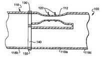
- FIG. 4is a sectional view of the mass flow rate sensor of FIG. 3 , further showing a first flow restrictor positioned between the main conduit and the sensor tube and a second flow restrictor positioned between the main conduit and the bypass tube;
- FIG. 5is an enlarged end elevation view of the first and the second flow restrictors.
- FIG. 6is a graph illustrating multiple gas bypass ratio errors for three gases versus flow rate for a mass flow rate sensor constructed in accordance with the present disclosure.
- FIGS. 3 and 4show an exemplary embodiment of a flow rate sensor 100 constructed in accordance with the present disclosure.
- the flow rate sensor 100can be used as part of a mass flow rate controller, such as the mass flow rate controller shown in FIG. 1 .
- the flow rate sensor 100 of the present disclosurereplaces the flow rate sensor 10 shown in FIGS. 1 and 2 .
- the present disclosureis also directed to a method of measuring flow and a method of controlling flow using the flow rate sensor 100 of FIGS. 3 and 4 .
- the metal used to make the first and the second porous media flow restrictors 130 , 140is selected from, but not limited to, a group consisting of stainless steel, nickel and nickel alloys, and titanium, to meet special requirements, such as greater temperature and corrosion resistance.
- the metals and alloysinclude, but are not limited to, Stainless Steel 316L, 304L, 310, 347 and 430, Hastelloy C-276, C-22, X, N, B and B2, Inconel 600, 625 and 690, Nickel 200 and Monel® 400 (70 Ni-30 Cu), Titanium, and Alloy 20.
- L tubeis the length of the tube and ⁇ p tube is the change of pressure of the gas over the length L tube of the tube.
- the above equationscan be used to design porous media flow restrictors 130 , 140 that make the flow sensor 100 substantially independent of gas properties.
- the porous mediamakes the bypass tube 118 a substantially independent of gas properties, while the multi-gas correction functions make the sensor tube 112 substantially independent of gas properties.
- the only potential error sourceis the assumption of fully developed flow in equation 3. In reality, however, the sensor tube 112 will have a pressure loss caused by entrance effects.
- the first porous media flow restrictor 130is designed so that the pressure drop ⁇ p 130 through the first porous media flow restrictor is much larger than the pressure drop ⁇ p 112 through the sensor tube 112 .
Landscapes
- Physics & Mathematics (AREA)
- Fluid Mechanics (AREA)
- General Physics & Mathematics (AREA)
- Measuring Volume Flow (AREA)
Abstract
Description
Δptube=Qtube(8μLtube/πrtube4) (5)
Δppm=Qpm(μtpm/Apmkpm) (6)
QsensorQ130=Q112
Qbypass=Q140=Q140 (7)
Δp100=Δp112+Δp130=Δp118+Δp140 (8)
Claims (27)
Priority Applications (7)
| Application Number | Priority Date | Filing Date | Title |
|---|---|---|---|
| US10/987,718US7121139B2 (en) | 2004-11-12 | 2004-11-12 | Thermal mass flow rate sensor having fixed bypass ratio |
| DE112005002770TDE112005002770T5 (en) | 2004-11-12 | 2005-10-26 | Thermal mass flow rate sensor with fixed shunt ratio |
| KR1020077012954AKR20070074663A (en) | 2004-11-12 | 2005-10-26 | Thermal Mass Flow Sensor with Fixed Vice Spab |
| JP2007541223AJP2008519981A (en) | 2004-11-12 | 2005-10-26 | Thermal mass flow sensor with predetermined bypass ratio |
| GB0708933AGB2434209A (en) | 2004-11-12 | 2005-10-26 | Thermal mass flow rate sensor having bypass ratio |
| PCT/US2005/039151WO2006055223A1 (en) | 2004-11-12 | 2005-10-26 | Thermal mass flow rate sensor having bypass ratio |
| TW094139522ATW200632288A (en) | 2004-11-12 | 2005-11-11 | Thermal mass flow rate sensor having fixed bypass ratio |
Applications Claiming Priority (1)
| Application Number | Priority Date | Filing Date | Title |
|---|---|---|---|
| US10/987,718US7121139B2 (en) | 2004-11-12 | 2004-11-12 | Thermal mass flow rate sensor having fixed bypass ratio |
Publications (2)
| Publication Number | Publication Date |
|---|---|
| US20060101907A1 US20060101907A1 (en) | 2006-05-18 |
| US7121139B2true US7121139B2 (en) | 2006-10-17 |
Family
ID=35788486
Family Applications (1)
| Application Number | Title | Priority Date | Filing Date |
|---|---|---|---|
| US10/987,718Expired - LifetimeUS7121139B2 (en) | 2004-11-12 | 2004-11-12 | Thermal mass flow rate sensor having fixed bypass ratio |
Country Status (7)
| Country | Link |
|---|---|
| US (1) | US7121139B2 (en) |
| JP (1) | JP2008519981A (en) |
| KR (1) | KR20070074663A (en) |
| DE (1) | DE112005002770T5 (en) |
| GB (1) | GB2434209A (en) |
| TW (1) | TW200632288A (en) |
| WO (1) | WO2006055223A1 (en) |
Cited By (19)
| Publication number | Priority date | Publication date | Assignee | Title |
|---|---|---|---|---|
| US20080250854A1 (en)* | 2007-04-12 | 2008-10-16 | Junhua Ding | Mass flow device using a flow equalizer for improving the output response |
| WO2012141852A3 (en)* | 2011-04-14 | 2012-12-06 | Trane International Inc. | Water flow measurement device |
| US8397586B2 (en) | 2010-03-22 | 2013-03-19 | Honeywell International Inc. | Flow sensor assembly with porous insert |
| US8418549B2 (en) | 2011-01-31 | 2013-04-16 | Honeywell International Inc. | Flow sensor assembly with integral bypass channel |
| US20130098486A1 (en)* | 2011-10-20 | 2013-04-25 | Honeywell International Inc. | Flow sensor with bypass taps in laminarizing channel and flow restrictor in a bpyass channel |
| US8485031B2 (en) | 2010-03-22 | 2013-07-16 | Honeywell International Inc. | Sensor assembly with hydrophobic filter |
| US8656772B2 (en) | 2010-03-22 | 2014-02-25 | Honeywell International Inc. | Flow sensor with pressure output signal |
| US8695417B2 (en) | 2011-01-31 | 2014-04-15 | Honeywell International Inc. | Flow sensor with enhanced flow range capability |
| US8756990B2 (en) | 2010-04-09 | 2014-06-24 | Honeywell International Inc. | Molded flow restrictor |
| US20150000655A1 (en)* | 2013-06-28 | 2015-01-01 | Carefusion 303, Inc. | Flow sensor |
| US9003877B2 (en) | 2010-06-15 | 2015-04-14 | Honeywell International Inc. | Flow sensor assembly |
| US9052217B2 (en) | 2012-11-09 | 2015-06-09 | Honeywell International Inc. | Variable scale sensor |
| US9707369B2 (en) | 2013-06-28 | 2017-07-18 | Vyaire Medical Capital Llc | Modular flow cassette |
| US9795757B2 (en) | 2013-06-28 | 2017-10-24 | Vyaire Medical Capital Llc | Fluid inlet adapter |
| US20180073901A1 (en)* | 2016-08-19 | 2018-03-15 | Cameron International Corporation | Assembly for control and/or measurement of fluid flow |
| US9952079B2 (en) | 2015-07-15 | 2018-04-24 | Honeywell International Inc. | Flow sensor |
| US9962514B2 (en) | 2013-06-28 | 2018-05-08 | Vyaire Medical Capital Llc | Ventilator flow valve |
| US10401206B2 (en)* | 2014-12-23 | 2019-09-03 | Endress + Hauser Flowtec Ag | Thermal, flow measuring device |
| US10495112B2 (en) | 2013-06-28 | 2019-12-03 | Vyaire Medical Capital Llc | Low-noise blower |
Families Citing this family (8)
| Publication number | Priority date | Publication date | Assignee | Title |
|---|---|---|---|---|
| GB2480881B (en) | 2010-06-04 | 2012-10-24 | Servomex Group Ltd | Thermal fluid flow apparatus |
| JP5969760B2 (en)* | 2011-12-27 | 2016-08-17 | 株式会社堀場エステック | Thermal flow sensor |
| US10139259B2 (en)* | 2014-12-05 | 2018-11-27 | General Electric Company | System and method for metering gas based on amplitude and/or temporal characteristics of an electrical signal |
| KR101682145B1 (en)* | 2015-08-20 | 2016-12-02 | 엠케이프리시젼 주식회사 | Thermal Mass Flow Meter with Sintered Filter |
| US20190070524A1 (en)* | 2017-09-06 | 2019-03-07 | Mott Corporation | Devices, systems, and methods for splitting fluid flows with porous media |
| US10837812B2 (en) | 2017-11-09 | 2020-11-17 | Honeywell International Inc | Miniature flow sensor with shroud |
| CN109117579B (en)* | 2018-08-30 | 2022-12-27 | 沈阳云仿致准科技股份有限公司 | Design calculation method of porous orifice plate flowmeter |
| WO2021113058A1 (en)* | 2019-12-02 | 2021-06-10 | Dow Silicones Corporation | Composition for preparing a release coating |
Citations (12)
| Publication number | Priority date | Publication date | Assignee | Title |
|---|---|---|---|---|
| US4433575A (en) | 1981-05-19 | 1984-02-28 | Rutherford Ralph E | Flow splitting device for fluid flow meter |
| US4522058A (en) | 1983-06-15 | 1985-06-11 | Mks Instruments, Inc. | Laminar-flow channeling in thermal flowmeters and the like |
| US5114447A (en) | 1991-03-12 | 1992-05-19 | Mott Metallurgical Corporation | Ultra-high efficiency porous metal filter |
| US5295394A (en) | 1991-06-13 | 1994-03-22 | Mks Japan Inc. | Bypass unit for a flowmeter sensor |
| US5332005A (en) | 1992-11-06 | 1994-07-26 | Aalborg Instruments & Controls, Inc. | Laminar flow element and method for metering fluid flow |
| US5750892A (en) | 1996-09-27 | 1998-05-12 | Teledyne Industries, Inc. | Laminar flow element with inboard sensor taps and coaxial laminar flow guides |
| US5804717A (en)* | 1996-04-05 | 1998-09-08 | Mks Instruments, Inc. | Mass flow transducer having extended flow rate measurement range |
| US5824894A (en) | 1997-05-07 | 1998-10-20 | Mks Instruments, Inc. | Mass flowmeter and laminar flow elements for use therein |
| US6119730A (en) | 1998-12-21 | 2000-09-19 | Mcmillan Company | Precision laminar flow element for use in thermal mass flow sensors and flow controllers |
| US6422256B1 (en) | 1998-10-08 | 2002-07-23 | Mott Metallurgical Corporation | Fluid flow controlling |
| US20030115950A1 (en) | 2001-12-21 | 2003-06-26 | Jesse Ambrosina | Apparatus and method for thermal dissipation in a thermal mass flow sensor |
| US6719947B1 (en) | 1998-05-08 | 2004-04-13 | Mott Metallurgical Corporation | Composite porous media |
Family Cites Families (11)
| Publication number | Priority date | Publication date | Assignee | Title |
|---|---|---|---|---|
| US3792609A (en)* | 1971-05-10 | 1974-02-19 | Tylan Corp | Flow splitter |
| SE421349B (en)* | 1977-12-16 | 1981-12-14 | Graende Per Olof | FLOOD METERS FOR REGISTERING REAL LOSS OF PULSED FLUID FLUID |
| US4282751A (en)* | 1979-08-29 | 1981-08-11 | Eaton Corporation | Fluid flowmeter |
| JPS609696Y2 (en)* | 1980-11-20 | 1985-04-05 | 株式会社日本自動車部品総合研究所 | Liquid level detection device |
| US4497202A (en)* | 1983-05-31 | 1985-02-05 | Dresser Industries, Inc. | Laminar flowmeter |
| DE3725312A1 (en)* | 1987-07-30 | 1989-02-09 | Jiri Hokynar | CONTROL UNIT FOR FLUID RIVER |
| US4800754A (en)* | 1987-10-07 | 1989-01-31 | Sierra Instruments, Inc. | Wide-range, adjustable flowmeter |
| JPH0422822A (en)* | 1990-05-17 | 1992-01-27 | Oval Corp | Thermal type flow meter |
| EP0677165B1 (en)* | 1993-09-07 | 2000-02-23 | Motorola, Inc. | System to determine engine misfire |
| FR2771817B1 (en)* | 1997-11-28 | 1999-12-31 | Schlumberger Ind Sa | DEVICE FOR MEASURING THE VISCOSITY OF A FLUID |
| US6332348B1 (en)* | 2000-01-05 | 2001-12-25 | Advanced Micro Devices, Inc. | Gas flow calibration of mass flow controllers |
- 2004
- 2004-11-12USUS10/987,718patent/US7121139B2/ennot_activeExpired - Lifetime
- 2005
- 2005-10-26KRKR1020077012954Apatent/KR20070074663A/ennot_activeWithdrawn
- 2005-10-26DEDE112005002770Tpatent/DE112005002770T5/ennot_activeWithdrawn
- 2005-10-26WOPCT/US2005/039151patent/WO2006055223A1/enactiveApplication Filing
- 2005-10-26JPJP2007541223Apatent/JP2008519981A/enactivePending
- 2005-10-26GBGB0708933Apatent/GB2434209A/ennot_activeWithdrawn
- 2005-11-11TWTW094139522Apatent/TW200632288A/enunknown
Patent Citations (12)
| Publication number | Priority date | Publication date | Assignee | Title |
|---|---|---|---|---|
| US4433575A (en) | 1981-05-19 | 1984-02-28 | Rutherford Ralph E | Flow splitting device for fluid flow meter |
| US4522058A (en) | 1983-06-15 | 1985-06-11 | Mks Instruments, Inc. | Laminar-flow channeling in thermal flowmeters and the like |
| US5114447A (en) | 1991-03-12 | 1992-05-19 | Mott Metallurgical Corporation | Ultra-high efficiency porous metal filter |
| US5295394A (en) | 1991-06-13 | 1994-03-22 | Mks Japan Inc. | Bypass unit for a flowmeter sensor |
| US5332005A (en) | 1992-11-06 | 1994-07-26 | Aalborg Instruments & Controls, Inc. | Laminar flow element and method for metering fluid flow |
| US5804717A (en)* | 1996-04-05 | 1998-09-08 | Mks Instruments, Inc. | Mass flow transducer having extended flow rate measurement range |
| US5750892A (en) | 1996-09-27 | 1998-05-12 | Teledyne Industries, Inc. | Laminar flow element with inboard sensor taps and coaxial laminar flow guides |
| US5824894A (en) | 1997-05-07 | 1998-10-20 | Mks Instruments, Inc. | Mass flowmeter and laminar flow elements for use therein |
| US6719947B1 (en) | 1998-05-08 | 2004-04-13 | Mott Metallurgical Corporation | Composite porous media |
| US6422256B1 (en) | 1998-10-08 | 2002-07-23 | Mott Metallurgical Corporation | Fluid flow controlling |
| US6119730A (en) | 1998-12-21 | 2000-09-19 | Mcmillan Company | Precision laminar flow element for use in thermal mass flow sensors and flow controllers |
| US20030115950A1 (en) | 2001-12-21 | 2003-06-26 | Jesse Ambrosina | Apparatus and method for thermal dissipation in a thermal mass flow sensor |
Non-Patent Citations (6)
| Title |
|---|
| High Purity Porous Metal Flow Restrictor, www.moticorp.com. |
| Molbloc/molbox Gas Flow Standards, www.dhinstruments.com. |
| PCT International Search Report for related PCT Application No.: PCT/US05/039151, 3 pages. |
| PCT Written Opinion of the International Searching Authority for related PCT Application No.: PCT/US05/039151, 7 pages. |
| Porous Metal Design Guidebook, www.mpif.org. |
| Precision Mass Flow Metering for CVD Applications, www.bronkhorst.com. |
Cited By (26)
| Publication number | Priority date | Publication date | Assignee | Title |
|---|---|---|---|---|
| US20080250854A1 (en)* | 2007-04-12 | 2008-10-16 | Junhua Ding | Mass flow device using a flow equalizer for improving the output response |
| US8656772B2 (en) | 2010-03-22 | 2014-02-25 | Honeywell International Inc. | Flow sensor with pressure output signal |
| US8397586B2 (en) | 2010-03-22 | 2013-03-19 | Honeywell International Inc. | Flow sensor assembly with porous insert |
| US8485031B2 (en) | 2010-03-22 | 2013-07-16 | Honeywell International Inc. | Sensor assembly with hydrophobic filter |
| US8756990B2 (en) | 2010-04-09 | 2014-06-24 | Honeywell International Inc. | Molded flow restrictor |
| US9003877B2 (en) | 2010-06-15 | 2015-04-14 | Honeywell International Inc. | Flow sensor assembly |
| US8418549B2 (en) | 2011-01-31 | 2013-04-16 | Honeywell International Inc. | Flow sensor assembly with integral bypass channel |
| US8695417B2 (en) | 2011-01-31 | 2014-04-15 | Honeywell International Inc. | Flow sensor with enhanced flow range capability |
| US9091577B2 (en) | 2011-01-31 | 2015-07-28 | Honeywell International Inc. | Flow sensor assembly with integral bypass channel |
| US9273986B2 (en) | 2011-04-14 | 2016-03-01 | Trane International Inc. | Water flow measurement device |
| WO2012141852A3 (en)* | 2011-04-14 | 2012-12-06 | Trane International Inc. | Water flow measurement device |
| US20130098486A1 (en)* | 2011-10-20 | 2013-04-25 | Honeywell International Inc. | Flow sensor with bypass taps in laminarizing channel and flow restrictor in a bpyass channel |
| US8826731B2 (en)* | 2011-10-20 | 2014-09-09 | Honeywell International Inc. | Flow sensor with bypass taps in laminarizing channel and flow restrictor in a bypass channel |
| US9052217B2 (en) | 2012-11-09 | 2015-06-09 | Honeywell International Inc. | Variable scale sensor |
| US20150000655A1 (en)* | 2013-06-28 | 2015-01-01 | Carefusion 303, Inc. | Flow sensor |
| US9707369B2 (en) | 2013-06-28 | 2017-07-18 | Vyaire Medical Capital Llc | Modular flow cassette |
| US9746359B2 (en)* | 2013-06-28 | 2017-08-29 | Vyaire Medical Capital Llc | Flow sensor |
| US9795757B2 (en) | 2013-06-28 | 2017-10-24 | Vyaire Medical Capital Llc | Fluid inlet adapter |
| US9962514B2 (en) | 2013-06-28 | 2018-05-08 | Vyaire Medical Capital Llc | Ventilator flow valve |
| US10495112B2 (en) | 2013-06-28 | 2019-12-03 | Vyaire Medical Capital Llc | Low-noise blower |
| US10539444B2 (en) | 2013-06-28 | 2020-01-21 | Vyaire Medical Capital Llc | Flow sensor |
| US10549063B2 (en) | 2013-06-28 | 2020-02-04 | Vyaire Medical Capital Llc | Modular flow cassette |
| US10401206B2 (en)* | 2014-12-23 | 2019-09-03 | Endress + Hauser Flowtec Ag | Thermal, flow measuring device |
| US9952079B2 (en) | 2015-07-15 | 2018-04-24 | Honeywell International Inc. | Flow sensor |
| US20180073901A1 (en)* | 2016-08-19 | 2018-03-15 | Cameron International Corporation | Assembly for control and/or measurement of fluid flow |
| US10337895B2 (en)* | 2016-08-19 | 2019-07-02 | Cameron International Corporation | Assembly for control and/or measurement of fluid flow |
Also Published As
| Publication number | Publication date |
|---|---|
| US20060101907A1 (en) | 2006-05-18 |
| DE112005002770T5 (en) | 2007-09-27 |
| KR20070074663A (en) | 2007-07-12 |
| JP2008519981A (en) | 2008-06-12 |
| WO2006055223A1 (en) | 2006-05-26 |
| TW200632288A (en) | 2006-09-16 |
| GB2434209A (en) | 2007-07-18 |
| GB0708933D0 (en) | 2007-06-20 |
Similar Documents
| Publication | Publication Date | Title |
|---|---|---|
| US7121139B2 (en) | Thermal mass flow rate sensor having fixed bypass ratio | |
| JP4594728B2 (en) | Flow controller based on higher accuracy pressure | |
| US7874208B2 (en) | System for and method of providing a wide-range flow controller | |
| US20060101908A1 (en) | Thermal mass flow rate sensor including bypass passageways and a sensor passageway having similar entrance effects | |
| US7467027B2 (en) | Compensation for thermal siphoning in mass flow controllers | |
| US7000463B1 (en) | Reynolds number correction function for mass flow rate sensor | |
| US9810377B2 (en) | System and method for improving the accuracy of a rate of decay (ROD) measurement in a mass flow controller | |
| WO1997038287A1 (en) | Mass flow transducer having extended flow rate measurement range | |
| CA2857065C (en) | Device and method for determining the mass-flow of a fluid | |
| EP3540382B1 (en) | Airflow sensor with gas composition correction | |
| Viswanathan et al. | Development, modeling and certain investigations on thermal mass flow meters | |
| WO2022069875A1 (en) | Gas flow sensor assembly, and semiconductor gas flow sensor and method of forming a semiconductor gas flow sensor | |
| US20030115951A1 (en) | Apparatus and method for thermal isolation of thermal mass flow sensor | |
| Olson | Heat transfer in thin, compact heat exchangers with circular, rectangular, or pin-fin flow passages | |
| JPH037243B2 (en) | ||
| US20220074775A1 (en) | Dual Tube Hybrid Coriolis Mass Flow Sensor | |
| KR20100111884A (en) | Mass flow meter and controller | |
| US6918295B1 (en) | Thermal mass flow rate sensor providing increased rate of heat transfer to gas | |
| Kim | Mathematical analysis of capillary thermal mass flow sensors for gas and liquid flow measurement | |
| CN214251092U (en) | Detector integrating flow meter and temperature sensor | |
| Olin | MEASUREMENTS 8c CONTROL | |
| JPH0325724B2 (en) | ||
| Kim et al. | Study on the transient characteristics of the sensor tube of a thermal mass flow meter | |
| Olson | Heat transfer in a compact heat exchanger containing rectangular channels and using helium gas | |
| Eid et al. | Online Measurements of Thermophysical Properties of Ideal Gas Mixture in Pipes |
Legal Events
| Date | Code | Title | Description |
|---|---|---|---|
| AS | Assignment | Owner name:MKS INSTRUMENTS, INC., MASSACHUSETTS Free format text:ASSIGNMENT OF ASSIGNORS INTEREST;ASSIGNORS:SHAJII, ALI;MENEGHINI, PAUL;SMITH, DANIEL ALEXANDER;REEL/FRAME:015997/0498 Effective date:20041103 | |
| STCF | Information on status: patent grant | Free format text:PATENTED CASE | |
| FPAY | Fee payment | Year of fee payment:4 | |
| FPAY | Fee payment | Year of fee payment:8 | |
| AS | Assignment | Owner name:DEUTSCHE BANK AG NEW YORK BRANCH, NEW YORK Free format text:SECURITY AGREEMENT;ASSIGNORS:MKS INSTRUMENTS, INC.;NEWPORT CORPORATION;REEL/FRAME:038663/0265 Effective date:20160429 Owner name:BARCLAYS BANK PLC, NEW YORK Free format text:SECURITY AGREEMENT;ASSIGNORS:MKS INSTRUMENTS, INC.;NEWPORT CORPORATION;REEL/FRAME:038663/0139 Effective date:20160429 | |
| MAFP | Maintenance fee payment | Free format text:PAYMENT OF MAINTENANCE FEE, 12TH YEAR, LARGE ENTITY (ORIGINAL EVENT CODE: M1553) Year of fee payment:12 | |
| AS | Assignment | Owner name:BARCLAYS BANK PLC, AS COLLATERAL AGENT, NEW YORK Free format text:PATENT SECURITY AGREEMENT (ABL);ASSIGNORS:ELECTRO SCIENTIFIC INDUSTRIES, INC.;MKS INSTRUMENTS, INC.;NEWPORT CORPORATION;REEL/FRAME:048211/0312 Effective date:20190201 Owner name:NEWPORT CORPORATION, CALIFORNIA Free format text:RELEASE BY SECURED PARTY;ASSIGNOR:DEUTSCHE BANK AG NEW YORK BRANCH;REEL/FRAME:048226/0095 Effective date:20190201 Owner name:MKS INSTRUMENTS, INC., MASSACHUSETTS Free format text:RELEASE BY SECURED PARTY;ASSIGNOR:DEUTSCHE BANK AG NEW YORK BRANCH;REEL/FRAME:048226/0095 Effective date:20190201 | |
| AS | Assignment | Owner name:BARCLAYS BANK PLC, AS COLLATERAL AGENT, NEW YORK Free format text:CORRECTIVE ASSIGNMENT TO CORRECT THE REMOVE U.S. PATENT NO.7,919,646 PREVIOUSLY RECORDED ON REEL 048211 FRAME 0312. ASSIGNOR(S) HEREBY CONFIRMS THE PATENT SECURITY AGREEMENT (ABL);ASSIGNORS:ELECTRO SCIENTIFIC INDUSTRIES, INC.;MKS INSTRUMENTS, INC.;NEWPORT CORPORATION;REEL/FRAME:055668/0687 Effective date:20190201 | |
| AS | Assignment | Owner name:JPMORGAN CHASE BANK, N.A., AS COLLATERAL AGENT, ILLINOIS Free format text:SECURITY INTEREST;ASSIGNORS:MKS INSTRUMENTS, INC.;NEWPORT CORPORATION;ELECTRO SCIENTIFIC INDUSTRIES, INC.;REEL/FRAME:061572/0069 Effective date:20220817 | |
| AS | Assignment | Owner name:ELECTRO SCIENTIFIC INDUSTRIES, INC., OREGON Free format text:RELEASE BY SECURED PARTY;ASSIGNOR:BARCLAYS BANK PLC;REEL/FRAME:063009/0001 Effective date:20220817 Owner name:NEWPORT CORPORATION, MASSACHUSETTS Free format text:RELEASE BY SECURED PARTY;ASSIGNOR:BARCLAYS BANK PLC;REEL/FRAME:063009/0001 Effective date:20220817 Owner name:MKS INSTRUMENTS, INC., MASSACHUSETTS Free format text:RELEASE BY SECURED PARTY;ASSIGNOR:BARCLAYS BANK PLC;REEL/FRAME:063009/0001 Effective date:20220817 Owner name:ELECTRO SCIENTIFIC INDUSTRIES, INC., OREGON Free format text:RELEASE BY SECURED PARTY;ASSIGNOR:BARCLAYS BANK PLC;REEL/FRAME:062739/0001 Effective date:20220817 Owner name:NEWPORT CORPORATION, MASSACHUSETTS Free format text:RELEASE BY SECURED PARTY;ASSIGNOR:BARCLAYS BANK PLC;REEL/FRAME:062739/0001 Effective date:20220817 Owner name:MKS INSTRUMENTS, INC., MASSACHUSETTS Free format text:RELEASE BY SECURED PARTY;ASSIGNOR:BARCLAYS BANK PLC;REEL/FRAME:062739/0001 Effective date:20220817 |