US7120819B1 - Method and system for fault diagnosis in a data network - Google Patents
Method and system for fault diagnosis in a data networkDownload PDFInfo
- Publication number
- US7120819B1 US7120819B1US09/998,846US99884601AUS7120819B1US 7120819 B1US7120819 B1US 7120819B1US 99884601 AUS99884601 AUS 99884601AUS 7120819 B1US7120819 B1US 7120819B1
- Authority
- US
- United States
- Prior art keywords
- data
- fault
- network
- fault data
- core
- Prior art date
- Legal status (The legal status is an assumption and is not a legal conclusion. Google has not performed a legal analysis and makes no representation as to the accuracy of the status listed.)
- Expired - Lifetime, expires
Links
Images


Classifications
- G—PHYSICS
- G06—COMPUTING OR CALCULATING; COUNTING
- G06F—ELECTRIC DIGITAL DATA PROCESSING
- G06F11/00—Error detection; Error correction; Monitoring
- G06F11/22—Detection or location of defective computer hardware by testing during standby operation or during idle time, e.g. start-up testing
- G06F11/2294—Detection or location of defective computer hardware by testing during standby operation or during idle time, e.g. start-up testing by remote test
Definitions
- the present inventionrelates to the field of network management. More specifically, the present invention relates to the self-diagnosis of faults within data networks.
- Network engineersmanage the data networks and must be familiar with their specific data network's topology, the behavior of all the devices on their network, and be able to process huge amounts of seemingly unrelated data.
- a single fault in the data networkcan produce hundreds and even thousands of alarms that must be analyzed by the NE, which is a prohibitive task.
- Traditional network fault diagnosisrequired the direct involvement with a NE who analyzed large amounts of seemingly unrelated fault data to determine what is causing the data network to operate improperly.
- the NEnecessarily must have expertise in troubleshooting, an understanding of network device behavior, and specific knowledge regarding their network, such as, topology, typical traffic conditions, applications, and legacy systems.
- One problem with the management of data networksis that fewer NEs with the necessary specialized expertise are available.
- NEsare responsible for more area within the field of network management to overcome the lack of NEs in the field.
- allocation of the resources provided by the NEis inefficient.
- a NEspends an inordinate amount of time monitoring and troubleshooting a data network in order to resolve problems on the network. That time could be better spent accomplishing other network management tasks.
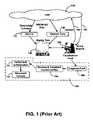
- FIG. 1is an illustration of the traditional fault management as a process.
- a NE 150has access to network data 130 and alarms 120 from a data network (e.g., local area network (LAN) 110 ).
- a network management toolcan be used to monitor and collect performance data in the form of remote monitoring (RMON) data (e.g., RMON-1 and RMON-2), alarms, or events where present thresholds have been crossed.
- RMONremote monitoring
- This datais aggregated and displayed to the NE in the form of display data 140 , such as, graphs and tables.
- a troubleshooting episodeis triggered by a user (not shown) of the data network 110 .
- the usercontacts the NE 150 with a problem regarding the network 110 .
- the usermay be experiencing slowness in responses transmitted through the network 110 , or the user may have lost connectivity.
- the NEcan analyze the display data 140 to manually troubleshoot the problem. Many times, the display data 140 is insufficient, and so the NE must query the data network, as represented by the path 180 of queries, to further isolate and diagnose the fault. This usually takes the form of scripts, such as, ping, or traceroute, and through the use of sniffers. The network 110 then sends back to the NE query results in path 185 .
- Block 190illustrates a flow chart of the process engaged by the NE 150 to perform troubleshooting.
- the NE 150analyses the fault data presented and diagnoses the fault.
- the NE 150develops and then implements a plan to correct the problem. Thereafter, the NE must verify the problem has been eliminated, in step 170 .
- a NEmay submit a report of the incident in step 175 .
- FIG. 1illustrates, the NE is responsible for isolating and identifying faults that are causing the problem. This can be time consuming and tedious, especially for large enterprise networks. As such, the analysis of fault data by the NE in today's larger heterogeneous networks is prone to error due to the large amounts of fault data to be manually processed.
- the present inventionprovides a method for self-diagnosing faults within a data network.
- One embodiment of the present inventionprovides a method that achieves the above accomplishment and which also provides for a method and system that lessens the burden on a network engineer when diagnosing faults. Additionally, one embodiment of the present invention provides a method and system that achieves the above accomplishments and which also provides for increased efficiency in the process of diagnosing faults within a data network.
- a network management stationreceives filtered fault data from the various subnetworks of computer systems that comprise the network.
- Each of the subnetworkshave an associated performance manager that monitors, collects and filters fault and network performance data from the subnetwork.
- Each of the performance managerssend their respective filtered data to the NMS.
- the NMSfurther analyses the filtered data to identify the fault and locate a source of the fault within the topology of the network.
- the NMScan further query the network for additional fault and network performance data as necessary.
- the NMSdisplays the fault, cause of the fault, and location of the fault to a network engineer for correction.
- FIG. 1is a block diagram illustrating the traditional primary role of the network engineer within a process for diagnosing a fault within a data network.
- FIG. 2illustrates a block diagram of an exemplary electronic device that is capable of diagnosing a fault in a data network, in accordance with one embodiment of the present invention.
- FIG. 3is a block diagram illustrating a process for self diagnosing a fault within a data network, in accordance with one embodiment of the present invention.
- FIG. 4is a diagram illustrating an exemplary data network that is capable of diagnosing faults, in accordance with one embodiment of the present invention.
- FIG. 5is a block diagram of an exemplary data network that is capable of diagnosing faults, in accordance with one embodiment of the present invention.
- FIG. 6is a flow diagram illustrating steps in a method for diagnosing faults within a data network, in accordance with one embodiment of the present invention.
- FIG. 7is a flow diagram illustrating steps in a method for analyzing fault data in order to identify two exemplary fault types and isolate the source of instances of the faults.
- FIG. 2is a block diagram of exemplary interior components of an exemplary computer system 200 , upon which embodiments of the present invention may be implemented.
- FIG. 2illustrates circuitry of an exemplary computer system 200 .
- Exemplary computer system 200includes an address/data bus 220 for communicating information, a central processor 201 coupled with the bus 220 for processing information and instructions, a volatile memory 202 (e.g., random access memory (RAM), static RAM dynamic RAM, etc.) coupled with the bus 220 for storing information and instructions for the central processor 201 , and a non-volatile memory 203 (e.g., read only memory (ROM), programmable ROM, flash memory, EPROM, EEPROM, etc.) coupled to the bus 220 for storing static information and instructions for the processor 201 .
- RAMrandom access memory
- EEPROMelectrically erasable programmable ROM
- FIG. 2illustrates circuitry of an exemplary computer system 200 .
- Exemplary computer system 200includes an address/data bus 220 for communicating information, a central processor 201 coupled with the bus 220 for processing information and instructions, a volatile memory 202 (e.g., random access memory (
- Exemplary computer system 200also includes an optional data storage device 204 (e.g., memory card, hard drive, etc.) coupled with the bus 220 for storing information and instructions. Data storage device 204 can be removable. Exemplary computer system 200 also contains an electronic display device 205 coupled to the bus 220 for displaying information to a user.
- the display device 205 utilized with the computer system 200may be a liquid crystal device, cathode ray tube (CRT), field emission device (FED, also called flat panel CRT) or other display device suitable for creating photographic or graphical images.
- CTRcathode ray tube
- FEDfield emission device
- Exemplary computer system 200also contains an alpha-numeric input 206 for communicating information and command selections to the central processor 201 .
- system 200also includes an optional cursor control or directing device 207 coupled to the bus 220 for communicating user input information and command selections to the central processor 201 .
- signal Input/Output device 208which is coupled to bus 220 for providing a communication link between computer system 200 and a network environment, is described. As such signal Input/Output device 208 enables the central processor unit 201 to communicate with or monitor other electronic systems or analog circuit blocks coupled to a data network.
- the present inventionprovides a method for diagnosing faults within a data network. Also, one embodiment of the present invention provides a method that lessens the burden on a network engineer for diagnosing faults within a data network. Still another embodiment of the present invention increases the efficiency of diagnosing faults within a data network.
- FIGS. 6 and 7illustrate a method for self diagnosing network faults within a data network, in the present invention.
- the FIGS. 3 , 4 , and 5provide a system architecture for implementing the method outlined in flow chart 600 of self diagnosing a data network.
- IPinternet-protocol
- TCP/IPTransmission Control Protocol/Internet Protocol
- Network faultscan be classified as hardware and software faults. These hardware and software faults can in turn cause other fault effects in the network such as congestion or even network failure.
- Examples of hardware faultsare failures of devices due to physical external events, such as, accidents (e.g., kicking a cable loose), mishandling, or improper installation, etc.
- Other hardware faultsare due to the aging of the device and/or weaknesses in the design of the hardware device.
- Software faultscause network devices to produce incorrect outputs.
- Software faultsoccur as slow or faulty service by the network due to incorrect information (e.g., erroneous router tables) or erratic behavior of the device due to software bugs, (e.g., incorrect processing of packets).
- Software faultscan also surface as lack of communication service if software tables have become corrupted (e.g., spanning tree loops that result in no packet forwarding at all).
- Flow chart 600includes processes of the present invention which, in one embodiment, are carried out by a processor under the control of computer-readable and computer executable instructions.
- the computer-readable and computer-executable instructionsreside, for example, in data storage features such as computer usable volatile memory 202 , computer usable non-volatile memory 203 , and/or data storage device 204 of FIG. 2 .
- the computer readable and computer-executable instructionsare used to control or operate in conjunction with, for example, central processing unit 201 of FIG. 2 .
- an exemplary communication network 300is shown that is capable of self diagnosing faults as illustrated by the flow chart 600 , in accordance with one embodiment of the present invention.
- system 300is a local area network (LAN), but other embodiments are well suited to other networks having a plurality of remotely located and coupled computer systems.
- the communication network 300is a transmission control protocol/internet protocol (TCP/IP) based data network.
- TCP/IPtransmission control protocol/internet protocol
- a generalized self diagnosing network (SDN) system 335controls the process 330 of automating the diagnosis of faults within the data network 300 .
- the SDN system 335receives a plurality of fault data, as illustrated in step 610 of flow chart 600 .
- the SDN system 335receives alarm data 310 from the data network 300 .
- Alarm data 310come in the form of alarms or events where preset thresholds within devices of the data network 300 have been exceeded or not been met.
- network data 315consists of performance data that is constantly monitored by a network management tool.
- the network data 315consists of the standardized remote monitoring 1&2 (RMON 1&2) data.
- the SDN system 335can also make further queries to the data network 300 for the fault diagnosis process if there is insufficient data.
- the SDN system 335sends queries 320 for fault data to devices on network 300 .
- the responses or query results 325are sent directly back to the SDN system 335 to be combined with the previously collected and received fault data.
- Block 330 of FIG. 3illustrates a generalized process for diagnosing faults within a data network 300 by the SDN system 335 .
- the steps illustrated in flow chart 600are embedded in the diagnosing fault block 340 of FIG. 3 .
- the present embodimentfilters the fault data to eliminate extraneous data.
- the filtering processsignificantly reduces the amount of fault data.
- alarm filteringcan be accomplished by eliminating multiple occurrences of the same alarm, inhibiting low priority alarms, generalizing alarms to their superclasses (as determined by domain experts), and replacing a specified occurrence of similar alarms with a single “count” alarm.
- Other embodimentsare well suited to the use of other filtering processes.
- the filtering processcan be implemented through rules or algorithms.
- the dataappears in the form of alarms, RMON 1&2 data, or any other suitable monitored data.
- the present embodimentalso correlates the alarms by substituting a new item for a set of alarms that match a predefined pattern. In one embodiment, this process can be approached as a pattern recognition problem.
- alarm correlationrequires the speedy analysis of large amounts of fault data.
- the fault datais quickly classified into recognized patterns, clusters, or categories of fault data.
- statistical and probabilistic approachesare appropriate, such as, using neural network analysis, or statistical algorithms.
- the outputtakes on the form of problem types and characteristics that are recognizable in troubleshooting the data network 300 .
- a core of fault datais produced by the SDN system 335 .
- This core of fault datais further analyzed by the SDN system 335 by the present embodiment, in step 630 of flow chart 600 .
- the analytical process of step 630detects the fault by identifying the type of fault and isolating the misbehaving device in the network that is the cause of the fault.
- the analytical process of fault detection in step 630requires a symbolic approach.
- the fault data that is filtered and correlated, and other suitable network datacan be analyzed to determine if more data must be obtained (e.g., obtained through the use of scripts, such as, ping or traceroute).
- the fault diagnosis process as outlined in flow chart 600is an iterative process.
- the present embodimentsends requests for more fault or network performance data, receives the answers to those request, and continues to troubleshoot the problem using the newly acquired information.
- flow chart 700illustrates steps in the analytical process that is outlined in step 630 of FIG. 6 , in accordance with one embodiment of the present invention. From step 630 , the present embodiment implements the analytical process by determining if the core of fault data is due to two example faults: a broken link or congestion within the data network 300 , in condition block 710 .
- the present embodiment via SDN system 335performs a ping walk in step 720 .
- the function of the ping walkis to traverse the network topology (or map) generated by a networking monitoring tool by pinging all the Internet Protocol (IP) addressed devices in the network 300 and identifying those that are not reachable from anywhere.
- IPInternet Protocol
- the results of the ping walkare compared to the network topology to determine the location of a broken link.
- the network topologyis produced by a network monitoring tool that produces a tree representation of the data network 300 which uses arcs and nodes to represent the network topology. Those well versed in the art understand that the arcs represent pings and the nodes represent devices on the network.
- flow chart 700proceeds to step 740 .
- congestionoccurs when a device or a link in the network is experiencing delay or packet loss due to congestion conditions such as, the load on the network or a bottleneck.
- Congestionis detected by examining traffic data that is monitored. Congestion collapse of a network occurs when the total productive work done by a network decreases significantly with an increase in the load on the network.
- the traffic datais comprised of delay, packet loss, and queue size, in one embodiment.
- a delay in a networkis an increase in time a packet has to wait at a network device before being forwarded.
- Packet lossis the percentage of packets which are dropped due to queue overflows.
- Queue sizeis the length of the packets queued at a network device. Queue size gives the earliest indication of congestion, followed by delay, and then by packet loss. If congestion is detected early, often only small adjustments are needed to cure the congestion.
- delayis commonly measured by looking at the round trip time of packets in the network.
- IPinternet protocol
- the present embodimentanalyses traffic data to determine the identity of the fault, due to congestion, that is associated with the core of fault data.
- Traffic datais RMON 1&2 data, or any other monitored network data, such as, delay.
- the present embodimentanalyses the traffic data to isolate the source of the core of fault data.
- the process of deductive reasoningis used to determine the type of fault, the cause of the fault, and the location of the fault.
- the deductive process used to identify and isolate the faultis implemented using fuzzy pattern matching technologies such as case-based reasoning or deductive/inductive logic techniques such as expert systems.
- the SDN system 335displays the results (e.g., identifying the type of fault, the cause, and the source of the fault) to the network engineer with an explanation of its reasoning, in accordance with one embodiment of the present invention.
- resultse.g., identifying the type of fault, the cause, and the source of the fault
- the network engineerwith an explanation of its reasoning, in accordance with one embodiment of the present invention.
- a short description of possible remedial or corrective actionsis developed and displayed to the NE as shown by block 347 .
- the SDN system 335 as illustrated in block 330 of FIG. 3illustrates the easing of the burden on the NE 150 by automating the fault diagnosis process. This is done by automating the analysis burden. However, in another embodiment, the NE continues to retain as much control over the automation process as is needed.
- the NEreceives information at a much later point than in the traditional fault diagnosis process as illustrated in Prior Art FIG. 1 .
- the burden of analyzing the large amounts of fault datais now provided by the SDN system 335 .
- the NEcan step in later in the fault diagnosis process and utilize the information provided by the SDN system 335 regarding fault identification and source isolation to take an appropriate corrective action, in block 350 .
- the NEcan further verify fault elimination in block 355 .
- the NEcan provide documentation of the fault and the remedies implemented.
- FIGS. 4 and 5are diagrams illustrating exemplary architectures of self diagnosing networks (SDN) systems.
- FIG. 4gives an exemplary architecture of a SDN system 400 .
- FIG. 5gives a block diagram of an exemplary SDN system 500 that is representative of the architecture of SDN system 400 .
- the SDN system 400is comprised of a multi-layered network.
- the lower layeris comprised of a plurality of subnetworks (subnets), e.g., subnet- 1 410 on up to subnet-n 420 .
- the plurality of scaleable subnetworkscreate the data network (e.g., the network LAN 300 of FIG. 3 ).
- edge devices and core devicesLocated within each of the subnetworks (e.g., subnet- 1 410 on up to subnet-n 420 ), are edge devices and core devices.
- the edge devicesare comprised of electronic systems, such as, computer systems, printers, facsimile machines, etc.
- the edge devicesare 410 a , 410 b , on up to 410 n .
- the edge devicesare 420 a , 420 b , on up to 420 n .
- Each of the edge devicesare capable of collecting RMON 1&2 data for network performance and fault monitoring that is used for fault analysis, in one embodiment.
- the core devices within the subnetworksare comprised of network support devices, such as, routers, switches, hubs, etc. Most of the core devices are also capable of collecting RMON 1&2 data for fault monitoring and fault analysis, in one embodiment.
- the core device 415is coupled to each of the edge devices, 410 a , 410 b , on up to 410 n .
- the core device 425is coupled to each of the edge devices, 420 a , 420 b , on up to 420 n.
- the RMON 1&2 data collected in each of edge devices of subnet- 1 410 and subnet- 2 420are passed on up to their respective core device and then sent to a middle layer edge monitor. For example, in subnet- 1 410 , the RMON 1&2 data is sent to the edge monitor 430 a . In subnet- 2 - 420 , the RMON 1&2 data is sent to the edge monitor 430 b.
- Each of the edge monitors at the middle layerprovide the filtering and correlating of the RMON 1&2 fault data produced by each of the edge and core devices located in their respective subnets, as illustrated in step 620 of the fault diagnosis process of flow chart 600 .
- the top layeris comprised of a network management station 440 that is coupled to each of the subnetworks (e.g., subnetwork- 1 410 on up to subnetwork-n 420 ) via their respective edge monitors (e.g., 430 a and 430 b ).
- the network management station 440provides the analysis portion of the SDN system 400 , as illustrated in step 630 of flow chart 600 .
- the station 440troubleshoots any problems experienced by the network 400 , further analyzes the core of fault data, and reports potential problems and solutions to the network engineer managing the network 400 .
- the SDN system 500is similar to the architecture of FIG. 4 , in accordance with one embodiment of the present invention.
- the SDN system 500is comprised of three layers, a lower layer 510 , a middle layer 520 , and a top layer 530 .
- the SDN system 500is capable of diagnosing faults within the communication system or network 550 .
- the lower layer 510 of FIG. 5is analogous to the core and edge devices that comprise each of the subnetworks (e.g., subnet- 1 410 and subnet-n 420 ).
- the lower layeris comprised of performance managers (e.g., 512 , 514 , on up to 517 ).
- Each of these performance managers devicessupply management information base (MIB) information to the SDN system 500 , such as RMON 1&2 data, in one embodiment.
- MIBmanagement information base
- Other embodimentsare well suited to other MIB tables to be incorporated in to the diagnostic system.
- the middle layer 520 of FIG. 5consists of SDN network performance managers (SDNnpm), such as, SDNnpm 522 , SDNnpm 524 , and SDNnpm 527 .
- SDNnpmSDN network performance managers
- the middle layer 520 of FIG. 5is analogous to each of the edge monitors ( 430 a and 430 b ) that are associated with respective subnetworks.
- the role of the SDNnpm (e.g., 522 , 524 , and 527 ) within the SDN system 500is to poll the various coupled performance managers devices (e.g., 512 , 514 , and 517 respectively) for MIB data, filter and correlate those data (e.g., step 620 of flow chart 600 ), and transfer the remaining data that has been filtered and correlated to the top layer 530 .
- various coupled performance managers devicese.g., 512 , 514 , and 517 respectively
- filter and correlate those datae.g., step 620 of flow chart 600
- the top layer 530 of FIG. 5consists of a SDN network management system (SDNnms) 535 .
- SDNnmsSDN network management system
- the SDNnms 535is analogous to the top network management station 440 .
- the SDNnms 535acts as the central control of the SDN system 500 and performs the fault diagnosis of the data network 550 , as illustrated in step 630 of flow chart 600 .
- the SDNnms 535interacts with a network topology system 540 for topology information regarding the network 550 .
- the topology system 540discovers the topology of the network 550 and supplies this topology to the SDNnms 535 in graphical form. Thereafter, the SDNnms 535 is able to perform fault diagnosis of the network 550 utilizing the network topology to isolate the source of faults due to broken links and congestion.
Landscapes
- Engineering & Computer Science (AREA)
- General Engineering & Computer Science (AREA)
- Theoretical Computer Science (AREA)
- Computer Hardware Design (AREA)
- Quality & Reliability (AREA)
- Physics & Mathematics (AREA)
- General Physics & Mathematics (AREA)
- Data Exchanges In Wide-Area Networks (AREA)
Abstract
Description
Claims (36)
Priority Applications (1)
| Application Number | Priority Date | Filing Date | Title |
|---|---|---|---|
| US09/998,846US7120819B1 (en) | 2001-11-15 | 2001-11-15 | Method and system for fault diagnosis in a data network |
Applications Claiming Priority (1)
| Application Number | Priority Date | Filing Date | Title |
|---|---|---|---|
| US09/998,846US7120819B1 (en) | 2001-11-15 | 2001-11-15 | Method and system for fault diagnosis in a data network |
Publications (1)
| Publication Number | Publication Date |
|---|---|
| US7120819B1true US7120819B1 (en) | 2006-10-10 |
Family
ID=37072537
Family Applications (1)
| Application Number | Title | Priority Date | Filing Date |
|---|---|---|---|
| US09/998,846Expired - LifetimeUS7120819B1 (en) | 2001-11-15 | 2001-11-15 | Method and system for fault diagnosis in a data network |
Country Status (1)
| Country | Link |
|---|---|
| US (1) | US7120819B1 (en) |
Cited By (64)
| Publication number | Priority date | Publication date | Assignee | Title |
|---|---|---|---|---|
| US20040141464A1 (en)* | 2003-01-21 | 2004-07-22 | Bellsouth Intellectual Property Corporation | Method and system for obtaining logical performance data for a circuit in a data network |
| US20040143653A1 (en)* | 2003-01-21 | 2004-07-22 | Bellsouth Intellectual Property Corporation | Method and system for provisioning and maintaining a circuit in a data network |
| US20040218591A1 (en)* | 2003-04-29 | 2004-11-04 | Craig Ogawa | Bridge apparatus and methods of operation |
| US20040249914A1 (en)* | 2003-05-21 | 2004-12-09 | Flocken Philip A. | Computer service using automated local diagnostic data collection and automated remote analysis |
| US20050050182A1 (en)* | 2003-08-26 | 2005-03-03 | Xerox Corporation | Peripheral device diagnostic method and architecture |
| US20050135263A1 (en)* | 2003-12-23 | 2005-06-23 | Bellsouth Intellectual Property Corporation | Method and system for real time simultaneous monitoring of logical circuits in a data network |
| US20050135238A1 (en)* | 2003-12-23 | 2005-06-23 | Bellsouth Intellectual Property Corporation | Method and system for providing a failover circuit for rerouting logical circuit data in a data network |
| US20050172160A1 (en)* | 2003-12-23 | 2005-08-04 | Bellsouth Intellectual Property Corporation | Method and system for automatically rerouting logical circuit data in a virtual private network |
| US20050216584A1 (en)* | 2004-03-24 | 2005-09-29 | Nortel Networks Limited | Method and apparatus for collecting management information on a communication network |
| US20050237943A1 (en)* | 2004-04-27 | 2005-10-27 | Yasushi Sasagawa | Transmission device |
| US20060146700A1 (en)* | 2003-12-23 | 2006-07-06 | Bellsouth Intellectual Property Corporation | Method and system for automatically renaming logical circuit identifiers for rerouted logical circuits in a data network |
| US20060198321A1 (en)* | 2005-03-04 | 2006-09-07 | Nadeau Thomas D | System and methods for network reachability detection |
| US20060218600A1 (en)* | 2005-03-01 | 2006-09-28 | Keith Johnson | System and method for identifying and isolating faults in a video on demand provisioning system |
| US20060242286A1 (en)* | 2003-05-21 | 2006-10-26 | Joshua Hawkins | Systems and methods for controlling error reporting and resolution |
| US20070294594A1 (en)* | 2006-05-18 | 2007-12-20 | The Boeing Company | Collaborative web-based airplane level failure effects analysis tool |
| US20070294584A1 (en)* | 2006-04-28 | 2007-12-20 | Microsoft Corporation | Detection and isolation of data items causing computer process crashes |
| US20080082867A1 (en)* | 2002-10-01 | 2008-04-03 | Rackmaster Systems, Inc. | Remote chassis monitoring system |
| US20080109681A1 (en)* | 2003-11-26 | 2008-05-08 | International Business Machines Corporation | Apparatus for Adaptive Problem Determination in Distributed Service-Based Applications |
| US20080155346A1 (en)* | 2006-10-13 | 2008-06-26 | Britt Steven V | Network fault pattern analyzer |
| US7434109B1 (en)* | 2002-09-26 | 2008-10-07 | Computer Associates Think, Inc. | Network fault manager for maintaining alarm conditions |
| US20080273472A1 (en)* | 2007-05-03 | 2008-11-06 | Adrian Bashford | Ethernet resource management |
| US20090003223A1 (en)* | 2007-06-29 | 2009-01-01 | Mccallum Gavin | Discovering configured tunnels between nodes on a path in a data communications network |
| US20090003345A1 (en)* | 2007-06-27 | 2009-01-01 | Steve Chen-Lin Chang | Network device dynamic help |
| US20090172474A1 (en)* | 2008-01-02 | 2009-07-02 | Virtual Instruments Corporation | Network Diagnostic Systems and Methods for Light Levels of Optical Signals |
| US7609623B2 (en) | 2003-12-23 | 2009-10-27 | At&T Intellectual Property I, L.P. | Method and system for automatically rerouting data from an overbalanced logical circuit in a data network |
| US20100146337A1 (en)* | 2008-12-10 | 2010-06-10 | Airbus Operations Sas | Method and device for detecting non-regression of an input/output system in a simulation environment |
| US7768904B2 (en) | 2004-04-22 | 2010-08-03 | At&T Intellectual Property I, L.P. | Method and system for fail-safe renaming of logical circuit identifiers for rerouted logical circuits in a data network |
| US20100218052A1 (en)* | 2009-02-23 | 2010-08-26 | International Business Machines Corporation | Apparatus and method to generate and collect diagnostic data |
| US7945817B1 (en)* | 2004-04-30 | 2011-05-17 | Sprint Communications Company L.P. | Method and system for automatically recognizing alarm patterns in a communications network |
| US7983174B1 (en)* | 2005-12-19 | 2011-07-19 | Cisco Technology, Inc. | Method and apparatus for diagnosing a fault in a network path |
| US8086907B1 (en)* | 2008-09-30 | 2011-12-27 | Juniper Networks, Inc. | Systems and methods for network information collection |
| US8094568B1 (en)* | 2005-04-22 | 2012-01-10 | At&T Intellectual Property Ii, L.P. | Method and apparatus for enabling auto-ticketing for endpoint devices |
| US8199638B2 (en) | 2003-12-23 | 2012-06-12 | At&T Intellectual Property I, L.P. | Method and system for automatically rerouting logical circuit data in a data network |
| US8203933B2 (en)* | 2003-12-23 | 2012-06-19 | At&T Intellectual Property I, L.P. | Method and system for automatically identifying a logical circuit failure in a data network |
| US8223632B2 (en) | 2003-12-23 | 2012-07-17 | At&T Intellectual Property I, L.P. | Method and system for prioritized rerouting of logical circuit data in a data network |
| US8295162B2 (en) | 2006-05-16 | 2012-10-23 | At&T Intellectual Property I, L.P. | System and method to achieve sub-second routing performance |
| US20120307624A1 (en)* | 2011-06-01 | 2012-12-06 | Cisco Technology, Inc. | Management of misbehaving nodes in a computer network |
| US8339938B2 (en) | 2004-04-22 | 2012-12-25 | At&T Intellectual Property I, L.P. | Method and system for automatically tracking the rerouting of logical circuit data in a data network |
| US8339988B2 (en) | 2004-04-22 | 2012-12-25 | At&T Intellectual Property I, L.P. | Method and system for provisioning logical circuits for intermittent use in a data network |
| US8345537B2 (en) | 2004-04-22 | 2013-01-01 | At&T Intellectual Property I, L.P. | Methods and systems for automatically rerouting logical circuit data from a logical circuit failure to a dedicated backup circuit in a data network |
| WO2013021316A1 (en)* | 2011-08-10 | 2013-02-14 | International Business Machines Corporation | A network management system |
| US8743889B2 (en) | 2010-07-06 | 2014-06-03 | Nicira, Inc. | Method and apparatus for using a network information base to control a plurality of shared network infrastructure switching elements |
| US20140280802A1 (en)* | 2013-03-15 | 2014-09-18 | Cisco Technology, Inc. | Capability identification and modification through hardware introspection and reflection |
| US9369360B1 (en)* | 2014-05-12 | 2016-06-14 | Google Inc. | Systems and methods for fault detection in large scale networks |
| US9467330B2 (en)* | 2013-10-14 | 2016-10-11 | Hewlett Packard Enterprise Development Lp | Diagnosing connectivity in a network |
| US20170048121A1 (en)* | 2015-08-13 | 2017-02-16 | Level 3 Communications, Llc | Systems and methods for managing network health |
| US20190044790A1 (en)* | 2017-08-02 | 2019-02-07 | International Business Machines Corporation | Testing and delivering verification of network configurations |
| US10298996B2 (en) | 2016-08-18 | 2019-05-21 | At&T Intellectual Property I, L.P. | Satellite TV user community smart device monitoring and management |
| WO2019241199A1 (en)* | 2018-06-12 | 2019-12-19 | Tier3 Technologies, Llc | System and method for predictive maintenance of networked devices |
| CN110661660A (en)* | 2019-09-25 | 2020-01-07 | 北京宝兰德软件股份有限公司 | Alarm information root analysis method and device |
| US10567246B2 (en) | 2015-12-15 | 2020-02-18 | At&T Intellectual Property I, L.P. | Processing performance data of a content delivery network |
| US10592821B2 (en) | 2015-06-19 | 2020-03-17 | Trane International Inc. | Self-learning fault detection for HVAC systems |
| US10684035B2 (en) | 2018-01-08 | 2020-06-16 | Trane International Inc. | HVAC system that collects customer feedback in connection with failure triage |
| US10911294B2 (en) | 2018-11-08 | 2021-02-02 | Vmware, Inc. | Method of diagnosing data delivery over a network between data centers |
| US11005777B2 (en) | 2018-07-10 | 2021-05-11 | At&T Intellectual Property I, L.P. | Software defined prober |
| WO2021158347A1 (en)* | 2020-02-04 | 2021-08-12 | Commscope Technologies Llc | Data analysis and configuration of a distributed radio access network |
| CN113485861A (en)* | 2021-07-08 | 2021-10-08 | 无锡江南计算技术研究所 | Basic layer fault diagnosis method and device based on resource optimization strategy |
| US20220086038A1 (en)* | 2015-11-20 | 2022-03-17 | Geotab Inc. | Big telematics data network communication fault identification device |
| US20220086753A1 (en)* | 2015-11-20 | 2022-03-17 | Geotab Inc. | Big telematics data network communication fault identification method |
| CN114490294A (en)* | 2021-11-10 | 2022-05-13 | 统信软件技术有限公司 | A system performance testing method, device and computing device for application software |
| US11677588B2 (en) | 2010-07-06 | 2023-06-13 | Nicira, Inc. | Network control apparatus and method for creating and modifying logical switching elements |
| US11755403B2 (en) | 2015-11-20 | 2023-09-12 | Geotab Inc. | Big telematics data network communication fault identification system |
| US11778563B2 (en) | 2015-11-20 | 2023-10-03 | Geotab Inc. | Big telematics data network communication fault identification system method |
| US11979280B2 (en) | 2010-07-06 | 2024-05-07 | Nicira, Inc. | Network control apparatus and method for populating logical datapath sets |
Citations (7)
| Publication number | Priority date | Publication date | Assignee | Title |
|---|---|---|---|---|
| US5404503A (en)* | 1991-02-05 | 1995-04-04 | Storage Technology Corporation | Hierarchical distributed knowledge based machine inititated maintenance system |
| US5790780A (en)* | 1996-07-16 | 1998-08-04 | Electronic Data Systems Corporation | Analysis of failures in a computing environment |
| US5872911A (en)* | 1995-12-29 | 1999-02-16 | Mci Communications Corporations | Method and system of service impact analysis in a communications network |
| US5936940A (en)* | 1996-08-22 | 1999-08-10 | International Business Machines Corporation | Adaptive rate-based congestion control in packet networks |
| US6289379B1 (en)* | 1997-11-07 | 2001-09-11 | Hitachi, Ltd. | Method for monitoring abnormal behavior in a computer system |
| US6304900B1 (en)* | 1999-02-18 | 2001-10-16 | International Business Machines Corporation | Data processing system and method for permitting a server computer system to remotely modify operation of a client system's network hardware |
| US6654914B1 (en)* | 1999-05-28 | 2003-11-25 | Teradyne, Inc. | Network fault isolation |
- 2001
- 2001-11-15USUS09/998,846patent/US7120819B1/ennot_activeExpired - Lifetime
Patent Citations (7)
| Publication number | Priority date | Publication date | Assignee | Title |
|---|---|---|---|---|
| US5404503A (en)* | 1991-02-05 | 1995-04-04 | Storage Technology Corporation | Hierarchical distributed knowledge based machine inititated maintenance system |
| US5872911A (en)* | 1995-12-29 | 1999-02-16 | Mci Communications Corporations | Method and system of service impact analysis in a communications network |
| US5790780A (en)* | 1996-07-16 | 1998-08-04 | Electronic Data Systems Corporation | Analysis of failures in a computing environment |
| US5936940A (en)* | 1996-08-22 | 1999-08-10 | International Business Machines Corporation | Adaptive rate-based congestion control in packet networks |
| US6289379B1 (en)* | 1997-11-07 | 2001-09-11 | Hitachi, Ltd. | Method for monitoring abnormal behavior in a computer system |
| US6304900B1 (en)* | 1999-02-18 | 2001-10-16 | International Business Machines Corporation | Data processing system and method for permitting a server computer system to remotely modify operation of a client system's network hardware |
| US6654914B1 (en)* | 1999-05-28 | 2003-11-25 | Teradyne, Inc. | Network fault isolation |
Cited By (146)
| Publication number | Priority date | Publication date | Assignee | Title |
|---|---|---|---|---|
| US7434109B1 (en)* | 2002-09-26 | 2008-10-07 | Computer Associates Think, Inc. | Network fault manager for maintaining alarm conditions |
| US8745435B2 (en)* | 2002-09-26 | 2014-06-03 | Ca, Inc. | Network fault manager |
| US8448012B2 (en) | 2002-09-26 | 2013-05-21 | Ca, Inc. | Network fault manager |
| US20090070640A1 (en)* | 2002-09-26 | 2009-03-12 | Stabile Lawrence A | Network fault manager for maintaining alarm conditions |
| US8015456B2 (en) | 2002-09-26 | 2011-09-06 | Computer Associates Think, Inc. | Network fault manager for maintaining alarm conditions |
| US7865764B2 (en)* | 2002-10-01 | 2011-01-04 | Rackmaster Systems, Inc. | Remote chassis monitoring system |
| US20080082867A1 (en)* | 2002-10-01 | 2008-04-03 | Rackmaster Systems, Inc. | Remote chassis monitoring system |
| US20040143653A1 (en)* | 2003-01-21 | 2004-07-22 | Bellsouth Intellectual Property Corporation | Method and system for provisioning and maintaining a circuit in a data network |
| US20040141464A1 (en)* | 2003-01-21 | 2004-07-22 | Bellsouth Intellectual Property Corporation | Method and system for obtaining logical performance data for a circuit in a data network |
| US20090103544A1 (en)* | 2003-01-21 | 2009-04-23 | At&T Intellectual Property I, L.P. | Method and system for provisioning and maintaining a circuit in a data network |
| US7469282B2 (en)* | 2003-01-21 | 2008-12-23 | At&T Intellectual Property I, L.P. | Method and system for provisioning and maintaining a circuit in a data network |
| US8200802B2 (en) | 2003-01-21 | 2012-06-12 | At&T Intellectual Property I, L.P. | Methods and systems for provisioning and maintaining a circuit in a data network |
| US7890618B2 (en) | 2003-01-21 | 2011-02-15 | At&T Intellectual Property I, L.P. | Method and system for provisioning and maintaining a circuit in a data network |
| US7391734B2 (en)* | 2003-01-21 | 2008-06-24 | At&T Delaware Intellectual Property Corporation, Inc. | Method and system for obtaining logical performance data for a circuit in a data network |
| US20040218591A1 (en)* | 2003-04-29 | 2004-11-04 | Craig Ogawa | Bridge apparatus and methods of operation |
| US9069666B2 (en) | 2003-05-21 | 2015-06-30 | Hewlett-Packard Development Company, L.P. | Systems and methods for controlling error reporting and resolution |
| US20040249914A1 (en)* | 2003-05-21 | 2004-12-09 | Flocken Philip A. | Computer service using automated local diagnostic data collection and automated remote analysis |
| US20060242286A1 (en)* | 2003-05-21 | 2006-10-26 | Joshua Hawkins | Systems and methods for controlling error reporting and resolution |
| US20050050182A1 (en)* | 2003-08-26 | 2005-03-03 | Xerox Corporation | Peripheral device diagnostic method and architecture |
| US20080109681A1 (en)* | 2003-11-26 | 2008-05-08 | International Business Machines Corporation | Apparatus for Adaptive Problem Determination in Distributed Service-Based Applications |
| US8547830B2 (en) | 2003-12-23 | 2013-10-01 | At&T Intellectual Property I, L.P. | Methods and systems to reroute data in a data network |
| US7630302B2 (en) | 2003-12-23 | 2009-12-08 | At&T Intellectual Property I, L.P. | Method and system for providing a failover circuit for rerouting logical circuit data in a data network |
| US8730795B2 (en) | 2003-12-23 | 2014-05-20 | At&T Intellectual Property I, L.P. | Methods and systems for automatically rerouting logical circuit data |
| US8750102B2 (en) | 2003-12-23 | 2014-06-10 | At&T Intellectual Property I, L.P. | Methods and systems for automatically rerouting logical circuit data in a data network |
| US8547831B2 (en) | 2003-12-23 | 2013-10-01 | At&T Intellectual Property I, L.P. | Methods and systems for automatically rerouting logical circuit data |
| US8937856B2 (en) | 2003-12-23 | 2015-01-20 | At&T Intellectual Property I, L.P. | Methods and systems to reroute data in a data network |
| US8942086B2 (en) | 2003-12-23 | 2015-01-27 | At&T Intellectual Property I, L.P. | Methods and systems for automatically rerouting logical circuit data in a data network |
| US20060146700A1 (en)* | 2003-12-23 | 2006-07-06 | Bellsouth Intellectual Property Corporation | Method and system for automatically renaming logical circuit identifiers for rerouted logical circuits in a data network |
| US8345543B2 (en) | 2003-12-23 | 2013-01-01 | At&T Intellectual Property I, L.P. | Methods and systems for automatically rerouting logical circuit data |
| US8243592B2 (en) | 2003-12-23 | 2012-08-14 | At&T Intellectual Property I, L.P. | Methods and systems for automatically rerouting data in a data network |
| US7609623B2 (en) | 2003-12-23 | 2009-10-27 | At&T Intellectual Property I, L.P. | Method and system for automatically rerouting data from an overbalanced logical circuit in a data network |
| US8711679B2 (en) | 2003-12-23 | 2014-04-29 | At&T Intellectual Property I, L.P. | Methods and systems for automatically identifying a logical circuit failure in a data network |
| US7639623B2 (en) | 2003-12-23 | 2009-12-29 | At&T Intellectual Property I, L.P. | Method and system for real time simultaneous monitoring of logical circuits in a data network |
| US7639606B2 (en) | 2003-12-23 | 2009-12-29 | At&T Intellectual Property I, L.P. | Method and system for automatically rerouting logical circuit data in a virtual private network |
| US8223632B2 (en) | 2003-12-23 | 2012-07-17 | At&T Intellectual Property I, L.P. | Method and system for prioritized rerouting of logical circuit data in a data network |
| US7646707B2 (en) | 2003-12-23 | 2010-01-12 | At&T Intellectual Property I, L.P. | Method and system for automatically renaming logical circuit identifiers for rerouted logical circuits in a data network |
| US9059900B2 (en) | 2003-12-23 | 2015-06-16 | At&T Intellectual Property I, L.P. | Methods and systems for automatically rerouting logical circuit data |
| US8203933B2 (en)* | 2003-12-23 | 2012-06-19 | At&T Intellectual Property I, L.P. | Method and system for automatically identifying a logical circuit failure in a data network |
| US20050172160A1 (en)* | 2003-12-23 | 2005-08-04 | Bellsouth Intellectual Property Corporation | Method and system for automatically rerouting logical circuit data in a virtual private network |
| US8199638B2 (en) | 2003-12-23 | 2012-06-12 | At&T Intellectual Property I, L.P. | Method and system for automatically rerouting logical circuit data in a data network |
| US8031588B2 (en) | 2003-12-23 | 2011-10-04 | At&T Intellectual Property I, L.P. | Methods and systems for automatically renaming logical Circuit identifiers for rerouted logical circuits in a data network |
| US8031620B2 (en) | 2003-12-23 | 2011-10-04 | At&T Intellectual Property I, L.P. | Method and system for real time simultaneous monitoring of logical circuits in a data network |
| US20050135238A1 (en)* | 2003-12-23 | 2005-06-23 | Bellsouth Intellectual Property Corporation | Method and system for providing a failover circuit for rerouting logical circuit data in a data network |
| US20050135263A1 (en)* | 2003-12-23 | 2005-06-23 | Bellsouth Intellectual Property Corporation | Method and system for real time simultaneous monitoring of logical circuits in a data network |
| US7657623B2 (en)* | 2004-03-24 | 2010-02-02 | Nortel Networks Limited | Method and apparatus for collecting management information on a communication network |
| US20050216584A1 (en)* | 2004-03-24 | 2005-09-29 | Nortel Networks Limited | Method and apparatus for collecting management information on a communication network |
| US8953495B2 (en) | 2004-04-22 | 2015-02-10 | At&T Intellectual Property I, L.P. | Methods and systems for provisioning logical circuits for intermittent use in a data network |
| US8339988B2 (en) | 2004-04-22 | 2012-12-25 | At&T Intellectual Property I, L.P. | Method and system for provisioning logical circuits for intermittent use in a data network |
| US9338051B2 (en) | 2004-04-22 | 2016-05-10 | At&T Intellectual Property I, L.P. | Methods and systems for automatically tracking the rerouting of logical circuit data in a data network |
| US8339938B2 (en) | 2004-04-22 | 2012-12-25 | At&T Intellectual Property I, L.P. | Method and system for automatically tracking the rerouting of logical circuit data in a data network |
| US7768904B2 (en) | 2004-04-22 | 2010-08-03 | At&T Intellectual Property I, L.P. | Method and system for fail-safe renaming of logical circuit identifiers for rerouted logical circuits in a data network |
| US8345537B2 (en) | 2004-04-22 | 2013-01-01 | At&T Intellectual Property I, L.P. | Methods and systems for automatically rerouting logical circuit data from a logical circuit failure to a dedicated backup circuit in a data network |
| US8953435B2 (en) | 2004-04-22 | 2015-02-10 | At&T Intellectual Property I, L.P. | Methods and systems for automatically tracking the rerouting of logical circuit data in a data network |
| US9148365B2 (en) | 2004-04-22 | 2015-09-29 | At&T Intellectual Property I, L.P. | Methods and systems for automatically tracking the rerouting of logical circuit data in a data network |
| US8737196B2 (en) | 2004-04-22 | 2014-05-27 | At&T Intellectual Property I, L.P. | Methods and systems for automatically tracking the rerouting of logical circuit data in a data network |
| US8670348B2 (en) | 2004-04-22 | 2014-03-11 | At&T Intellectual Property I, L.P. | Methods and systems for provisioning logical circuits for intermittent use in a data network |
| US8665705B2 (en) | 2004-04-22 | 2014-03-04 | At&T Intellectual Property I, L.P. | Methods and systems for automatically rerouting logical circuit data from a logical circuit failure to a dedicated backup circuit in a data network |
| US8565074B2 (en) | 2004-04-22 | 2013-10-22 | At&T Intellectual Property I, L.P. | Methods and systems for automatically tracking the rerouting of logical circuit data in a data network |
| US8509118B2 (en) | 2004-04-22 | 2013-08-13 | At&T Intellectual Property I, L.P. | Methods and systems for provisioning logical circuits for intermittent use in a data network |
| US8509058B2 (en) | 2004-04-22 | 2013-08-13 | At&T Intellectual Property I, L.P. | Methods and systems for automatically rerouting logical circuit data from a logical circuit failure to a dedicated backup circuit in a data network |
| US20050237943A1 (en)* | 2004-04-27 | 2005-10-27 | Yasushi Sasagawa | Transmission device |
| US7945817B1 (en)* | 2004-04-30 | 2011-05-17 | Sprint Communications Company L.P. | Method and system for automatically recognizing alarm patterns in a communications network |
| US20060218600A1 (en)* | 2005-03-01 | 2006-09-28 | Keith Johnson | System and method for identifying and isolating faults in a video on demand provisioning system |
| US7383473B2 (en)* | 2005-03-01 | 2008-06-03 | Time Warner Cable, Inc. | System and method for identifying and isolating faults in a video on demand provisioning system |
| US7990888B2 (en) | 2005-03-04 | 2011-08-02 | Cisco Technology, Inc. | System and methods for network reachability detection |
| US20060198321A1 (en)* | 2005-03-04 | 2006-09-07 | Nadeau Thomas D | System and methods for network reachability detection |
| US8094568B1 (en)* | 2005-04-22 | 2012-01-10 | At&T Intellectual Property Ii, L.P. | Method and apparatus for enabling auto-ticketing for endpoint devices |
| US8687502B2 (en) | 2005-04-22 | 2014-04-01 | At&T Intellectual Property Ii, L.P. | Method and apparatus for enabling auto-ticketing for endpoint devices |
| US7983174B1 (en)* | 2005-12-19 | 2011-07-19 | Cisco Technology, Inc. | Method and apparatus for diagnosing a fault in a network path |
| US20070294584A1 (en)* | 2006-04-28 | 2007-12-20 | Microsoft Corporation | Detection and isolation of data items causing computer process crashes |
| US8295162B2 (en) | 2006-05-16 | 2012-10-23 | At&T Intellectual Property I, L.P. | System and method to achieve sub-second routing performance |
| US8873379B2 (en) | 2006-05-16 | 2014-10-28 | At&T Intellectual Property I, L.P. | System and method to achieve sub-second routing performance |
| US20070294594A1 (en)* | 2006-05-18 | 2007-12-20 | The Boeing Company | Collaborative web-based airplane level failure effects analysis tool |
| US7770052B2 (en)* | 2006-05-18 | 2010-08-03 | The Boeing Company | Collaborative web-based airplane level failure effects analysis tool |
| US20080155346A1 (en)* | 2006-10-13 | 2008-06-26 | Britt Steven V | Network fault pattern analyzer |
| US7647530B2 (en)* | 2006-10-13 | 2010-01-12 | Hewlett-Packard Development Company, L.P. | Network fault pattern analyzer |
| US20080273472A1 (en)* | 2007-05-03 | 2008-11-06 | Adrian Bashford | Ethernet resource management |
| US20090003345A1 (en)* | 2007-06-27 | 2009-01-01 | Steve Chen-Lin Chang | Network device dynamic help |
| US20090003223A1 (en)* | 2007-06-29 | 2009-01-01 | Mccallum Gavin | Discovering configured tunnels between nodes on a path in a data communications network |
| US8111627B2 (en) | 2007-06-29 | 2012-02-07 | Cisco Technology, Inc. | Discovering configured tunnels between nodes on a path in a data communications network |
| US20090172474A1 (en)* | 2008-01-02 | 2009-07-02 | Virtual Instruments Corporation | Network Diagnostic Systems and Methods for Light Levels of Optical Signals |
| WO2009088918A1 (en)* | 2008-01-02 | 2009-07-16 | Virtual Instruments Corporation | Network diagnostic systems and methods for light levels of optical signals |
| US8086907B1 (en)* | 2008-09-30 | 2011-12-27 | Juniper Networks, Inc. | Systems and methods for network information collection |
| US20120072764A1 (en)* | 2008-09-30 | 2012-03-22 | Juniper Networks, Inc. | Systems and methods for network information collection |
| US8381044B2 (en)* | 2008-09-30 | 2013-02-19 | Juniper Networks, Inc. | Systems and methods for network information collection |
| US20100146337A1 (en)* | 2008-12-10 | 2010-06-10 | Airbus Operations Sas | Method and device for detecting non-regression of an input/output system in a simulation environment |
| FR2939532A1 (en)* | 2008-12-10 | 2010-06-11 | Airbus France | METHOD AND DEVICE FOR DETECTING NON-REGRESSION OF AN INPUT / OUTPUT SYSTEM IN A SIMULATION ENVIRONMENT |
| EP2196909A1 (en) | 2008-12-10 | 2010-06-16 | Airbus Opérations | Method and apparatus for detecting non regression of an input-output system within a simulation environment |
| US20100218052A1 (en)* | 2009-02-23 | 2010-08-26 | International Business Machines Corporation | Apparatus and method to generate and collect diagnostic data |
| US8112676B2 (en)* | 2009-02-23 | 2012-02-07 | International Business Machines Corporation | Apparatus and method to generate and collect diagnostic data |
| US9106587B2 (en) | 2010-07-06 | 2015-08-11 | Nicira, Inc. | Distributed network control system with one master controller per managed switching element |
| US9008087B2 (en) | 2010-07-06 | 2015-04-14 | Nicira, Inc. | Processing requests in a network control system with multiple controller instances |
| US11223531B2 (en) | 2010-07-06 | 2022-01-11 | Nicira, Inc. | Method and apparatus for interacting with a network information base in a distributed network control system with multiple controller instances |
| US8880468B2 (en)* | 2010-07-06 | 2014-11-04 | Nicira, Inc. | Secondary storage architecture for a network control system that utilizes a primary network information base |
| US11509564B2 (en) | 2010-07-06 | 2022-11-22 | Nicira, Inc. | Method and apparatus for replicating network information base in a distributed network control system with multiple controller instances |
| US8775594B2 (en) | 2010-07-06 | 2014-07-08 | Nicira, Inc. | Distributed network control system with a distributed hash table |
| US11539591B2 (en) | 2010-07-06 | 2022-12-27 | Nicira, Inc. | Distributed network control system with one master controller per logical datapath set |
| US8743889B2 (en) | 2010-07-06 | 2014-06-03 | Nicira, Inc. | Method and apparatus for using a network information base to control a plurality of shared network infrastructure switching elements |
| US8966040B2 (en) | 2010-07-06 | 2015-02-24 | Nicira, Inc. | Use of network information base structure to establish communication between applications |
| US9391928B2 (en) | 2010-07-06 | 2016-07-12 | Nicira, Inc. | Method and apparatus for interacting with a network information base in a distributed network control system with multiple controller instances |
| US8842679B2 (en) | 2010-07-06 | 2014-09-23 | Nicira, Inc. | Control system that elects a master controller instance for switching elements |
| US10326660B2 (en) | 2010-07-06 | 2019-06-18 | Nicira, Inc. | Network virtualization apparatus and method |
| US11677588B2 (en) | 2010-07-06 | 2023-06-13 | Nicira, Inc. | Network control apparatus and method for creating and modifying logical switching elements |
| US11876679B2 (en) | 2010-07-06 | 2024-01-16 | Nicira, Inc. | Method and apparatus for interacting with a network information base in a distributed network control system with multiple controller instances |
| US9172663B2 (en) | 2010-07-06 | 2015-10-27 | Nicira, Inc. | Method and apparatus for replicating network information base in a distributed network control system with multiple controller instances |
| US11979280B2 (en) | 2010-07-06 | 2024-05-07 | Nicira, Inc. | Network control apparatus and method for populating logical datapath sets |
| US12028215B2 (en) | 2010-07-06 | 2024-07-02 | Nicira, Inc. | Distributed network control system with one master controller per logical datapath set |
| CN103609067B (en)* | 2011-06-01 | 2018-02-09 | 思科技术公司 | Management to misbehaving node in computer network |
| CN103609067A (en)* | 2011-06-01 | 2014-02-26 | 思科技术公司 | Management of misbehaving nodes in a computer network |
| US20120307624A1 (en)* | 2011-06-01 | 2012-12-06 | Cisco Technology, Inc. | Management of misbehaving nodes in a computer network |
| WO2013021316A1 (en)* | 2011-08-10 | 2013-02-14 | International Business Machines Corporation | A network management system |
| US9253023B2 (en)* | 2011-08-10 | 2016-02-02 | International Business Machines Corporation | Network management system with a switchable flood revention mode pregarding fault events for a managed device |
| CN103733567B (en)* | 2011-08-10 | 2016-10-12 | 国际商业机器公司 | Nms |
| GB2506323A (en)* | 2011-08-10 | 2014-03-26 | Ibm | A network management system |
| CN103733567A (en)* | 2011-08-10 | 2014-04-16 | 国际商业机器公司 | A network management system |
| US20140173109A1 (en)* | 2011-08-10 | 2014-06-19 | International Business Machines Corporation | Network Management System |
| GB2506323B (en)* | 2011-08-10 | 2014-07-16 | Ibm | A network management system |
| US20140280802A1 (en)* | 2013-03-15 | 2014-09-18 | Cisco Technology, Inc. | Capability identification and modification through hardware introspection and reflection |
| US9467330B2 (en)* | 2013-10-14 | 2016-10-11 | Hewlett Packard Enterprise Development Lp | Diagnosing connectivity in a network |
| US9369360B1 (en)* | 2014-05-12 | 2016-06-14 | Google Inc. | Systems and methods for fault detection in large scale networks |
| US10592821B2 (en) | 2015-06-19 | 2020-03-17 | Trane International Inc. | Self-learning fault detection for HVAC systems |
| US10498588B2 (en)* | 2015-08-13 | 2019-12-03 | Level 3 Communications, Llc | Systems and methods for managing network health |
| US20170048121A1 (en)* | 2015-08-13 | 2017-02-16 | Level 3 Communications, Llc | Systems and methods for managing network health |
| US20220086038A1 (en)* | 2015-11-20 | 2022-03-17 | Geotab Inc. | Big telematics data network communication fault identification device |
| US11881988B2 (en)* | 2015-11-20 | 2024-01-23 | Geotab Inc. | Big telematics data network communication fault identification device |
| US11800446B2 (en)* | 2015-11-20 | 2023-10-24 | Geotab Inc. | Big telematics data network communication fault identification method |
| US11778563B2 (en) | 2015-11-20 | 2023-10-03 | Geotab Inc. | Big telematics data network communication fault identification system method |
| US11755403B2 (en) | 2015-11-20 | 2023-09-12 | Geotab Inc. | Big telematics data network communication fault identification system |
| US20220086753A1 (en)* | 2015-11-20 | 2022-03-17 | Geotab Inc. | Big telematics data network communication fault identification method |
| US11316762B2 (en) | 2015-12-15 | 2022-04-26 | At&T Intellectual Property I, L.P. | Processing performance data of a content delivery network |
| US10567246B2 (en) | 2015-12-15 | 2020-02-18 | At&T Intellectual Property I, L.P. | Processing performance data of a content delivery network |
| US10298996B2 (en) | 2016-08-18 | 2019-05-21 | At&T Intellectual Property I, L.P. | Satellite TV user community smart device monitoring and management |
| US10805671B2 (en) | 2016-08-18 | 2020-10-13 | At&T Intellectual Property I, L.P. | Satellite TV user community smart device monitoring and management |
| US20190044789A1 (en)* | 2017-08-02 | 2019-02-07 | International Business Machines Corporation | Testing and delivering verification of network configurations |
| US10771322B2 (en)* | 2017-08-02 | 2020-09-08 | International Business Machines Corporation | Testing and delivering verification of network configurations |
| US20190044790A1 (en)* | 2017-08-02 | 2019-02-07 | International Business Machines Corporation | Testing and delivering verification of network configurations |
| US10771321B2 (en)* | 2017-08-02 | 2020-09-08 | International Business Machines Corporation | Testing and delivering verification of network configurations |
| US10684035B2 (en) | 2018-01-08 | 2020-06-16 | Trane International Inc. | HVAC system that collects customer feedback in connection with failure triage |
| WO2019241199A1 (en)* | 2018-06-12 | 2019-12-19 | Tier3 Technologies, Llc | System and method for predictive maintenance of networked devices |
| US11005777B2 (en) | 2018-07-10 | 2021-05-11 | At&T Intellectual Property I, L.P. | Software defined prober |
| US10911294B2 (en) | 2018-11-08 | 2021-02-02 | Vmware, Inc. | Method of diagnosing data delivery over a network between data centers |
| CN110661660A (en)* | 2019-09-25 | 2020-01-07 | 北京宝兰德软件股份有限公司 | Alarm information root analysis method and device |
| CN110661660B (en)* | 2019-09-25 | 2021-09-10 | 北京宝兰德软件股份有限公司 | Alarm information root analysis method and device |
| WO2021158347A1 (en)* | 2020-02-04 | 2021-08-12 | Commscope Technologies Llc | Data analysis and configuration of a distributed radio access network |
| CN113485861A (en)* | 2021-07-08 | 2021-10-08 | 无锡江南计算技术研究所 | Basic layer fault diagnosis method and device based on resource optimization strategy |
| CN114490294A (en)* | 2021-11-10 | 2022-05-13 | 统信软件技术有限公司 | A system performance testing method, device and computing device for application software |
Similar Documents
| Publication | Publication Date | Title |
|---|---|---|
| US7120819B1 (en) | Method and system for fault diagnosis in a data network | |
| AU2021200243B2 (en) | Systems and methods for an interactive network analysis platform | |
| DE602005000383T2 (en) | Error detection and diagnostics | |
| EP0909056B1 (en) | Network management event correlation in environments containing inoperative network elements | |
| US6363384B1 (en) | Expert system process flow | |
| US7249286B1 (en) | System and method for automatically diagnosing protocol errors from packet traces | |
| US6526044B1 (en) | Real-time analysis through capture buffer with real-time historical data correlation | |
| US6529954B1 (en) | Knowledge based expert analysis system | |
| US8370466B2 (en) | Method and system for providing operator guidance in network and systems management | |
| EP0503784B1 (en) | Hypothesis and conclusion method to diagnose data communication network | |
| US7962592B2 (en) | System and method for network management | |
| US7180856B1 (en) | Method and system of monitoring the receipt of multicast traffic | |
| US20110270957A1 (en) | Method and system for logging trace events of a network device | |
| US20070274234A1 (en) | Network management method | |
| US20210126844A1 (en) | Application aware device monitoring correlation and visualization | |
| US11032124B1 (en) | Application aware device monitoring | |
| US20060085680A1 (en) | Network monitoring method and apparatus | |
| US20060168263A1 (en) | Monitoring telecommunication network elements | |
| US20040006619A1 (en) | Structure for event reporting in SNMP systems | |
| CN110224883A (en) | A kind of Grey Fault Diagnosis method applied to telecommunications bearer network | |
| KR100887874B1 (en) | Disability Management System and Method in Internet Network | |
| CN114244682B (en) | Equipment alarm loss and leakage repairing method and device | |
| DE102023126512A1 (en) | MECHANISM FOR AN INTELLIGENT AND COMPREHENSIVE SURVEILLANCE SYSTEM WITH PEER-TO-PEER AGENTS IN A NETWORK | |
| US8284044B2 (en) | Poll-based alarm handling system and method | |
| CN115913903B (en) | A method and system for automatically repairing network failures of network equipment of a recording master station |
Legal Events
| Date | Code | Title | Description |
|---|---|---|---|
| AS | Assignment | Owner name:3COM CORPORATION, CALIFORNIA Free format text:ASSIGNMENT OF ASSIGNORS INTEREST;ASSIGNORS:GURER, DENISE;LUSHER, ELAINE;REEL/FRAME:012738/0811;SIGNING DATES FROM 20020208 TO 20020219 | |
| STCF | Information on status: patent grant | Free format text:PATENTED CASE | |
| FPAY | Fee payment | Year of fee payment:4 | |
| AS | Assignment | Owner name:HEWLETT-PACKARD COMPANY, CALIFORNIA Free format text:MERGER;ASSIGNOR:3COM CORPORATION;REEL/FRAME:024630/0820 Effective date:20100428 | |
| AS | Assignment | Owner name:HEWLETT-PACKARD COMPANY, CALIFORNIA Free format text:CORRECTIVE ASSIGNMENT TO CORRECT THE SEE ATTACHED;ASSIGNOR:3COM CORPORATION;REEL/FRAME:025039/0844 Effective date:20100428 | |
| AS | Assignment | Owner name:HEWLETT-PACKARD DEVELOPMENT COMPANY, L.P., TEXAS Free format text:ASSIGNMENT OF ASSIGNORS INTEREST;ASSIGNOR:HEWLETT-PACKARD COMPANY;REEL/FRAME:027329/0044 Effective date:20030131 | |
| AS | Assignment | Owner name:HEWLETT-PACKARD DEVELOPMENT COMPANY, L.P., TEXAS Free format text:CORRECTIVE ASSIGNMENT PREVIUOSLY RECORDED ON REEL 027329 FRAME 0001 AND 0044;ASSIGNOR:HEWLETT-PACKARD COMPANY;REEL/FRAME:028911/0846 Effective date:20111010 | |
| FPAY | Fee payment | Year of fee payment:8 | |
| AS | Assignment | Owner name:HEWLETT PACKARD ENTERPRISE DEVELOPMENT LP, TEXAS Free format text:ASSIGNMENT OF ASSIGNORS INTEREST;ASSIGNOR:HEWLETT-PACKARD DEVELOPMENT COMPANY, L.P.;REEL/FRAME:037079/0001 Effective date:20151027 | |
| MAFP | Maintenance fee payment | Free format text:PAYMENT OF MAINTENANCE FEE, 12TH YEAR, LARGE ENTITY (ORIGINAL EVENT CODE: M1553) Year of fee payment:12 | |
| AS | Assignment | Owner name:VALTRUS INNOVATIONS LIMITED, IRELAND Free format text:ASSIGNMENT OF ASSIGNORS INTEREST;ASSIGNORS:HEWLETT PACKARD ENTERPRISE DEVELOPMENT LP;HEWLETT PACKARD ENTERPRISE COMPANY;REEL/FRAME:055360/0424 Effective date:20210121 |