US7120457B2 - Transmission control method and apparatus for mobile communication system - Google Patents
Transmission control method and apparatus for mobile communication systemDownload PDFInfo
- Publication number
- US7120457B2 US7120457B2US10/376,310US37631003AUS7120457B2US 7120457 B2US7120457 B2US 7120457B2US 37631003 AUS37631003 AUS 37631003AUS 7120457 B2US7120457 B2US 7120457B2
- Authority
- US
- United States
- Prior art keywords
- mobile terminal
- base station
- power control
- link
- control information
- Prior art date
- Legal status (The legal status is an assumption and is not a legal conclusion. Google has not performed a legal analysis and makes no representation as to the accuracy of the status listed.)
- Expired - Fee Related, expires
Links
Images


Classifications
- H—ELECTRICITY
- H04—ELECTRIC COMMUNICATION TECHNIQUE
- H04W—WIRELESS COMMUNICATION NETWORKS
- H04W52/00—Power management, e.g. Transmission Power Control [TPC] or power classes
- H04W52/04—Transmission power control [TPC]
- H04W52/30—Transmission power control [TPC] using constraints in the total amount of available transmission power
- H04W52/36—Transmission power control [TPC] using constraints in the total amount of available transmission power with a discrete range or set of values, e.g. step size, ramping or offsets
- H04W52/362—Aspects of the step size
- H—ELECTRICITY
- H04—ELECTRIC COMMUNICATION TECHNIQUE
- H04W—WIRELESS COMMUNICATION NETWORKS
- H04W52/00—Power management, e.g. Transmission Power Control [TPC] or power classes
- H04W52/04—Transmission power control [TPC]
- H04W52/30—Transmission power control [TPC] using constraints in the total amount of available transmission power
- H—ELECTRICITY
- H04—ELECTRIC COMMUNICATION TECHNIQUE
- H04W—WIRELESS COMMUNICATION NETWORKS
- H04W52/00—Power management, e.g. Transmission Power Control [TPC] or power classes
- H04W52/04—Transmission power control [TPC]
- H04W52/18—TPC being performed according to specific parameters
- H04W52/24—TPC being performed according to specific parameters using SIR [Signal to Interference Ratio] or other wireless path parameters
- H04W52/248—TPC being performed according to specific parameters using SIR [Signal to Interference Ratio] or other wireless path parameters where transmission power control commands are generated based on a path parameter
Definitions
- the present inventiongenerally relates to a transmission power control method and apparatus for mobile communication system which controls the transmission power between the base station and mobile terminal of a mobile communication system, and particularly to the effective technology suitable for use in the transmission power control method and apparatus for mobile communication system which controls the transmission power in accordance with the change of signals received between the base station and mobile terminal of the mobile communication system of TDD-SS (Time Division Duplex-Spread Spectrum) and FDD (Frequency Division Duplex) system.
- TDD-SSTime Division Duplex-Spread Spectrum
- FDDFrequency Division Duplex
- This mobile communication systememploys different carrier frequencies for the up link on which signals are transmitted from a mobile terminal to the base station and for the down link on which signals are transmitted from the base station to the mobile terminal by the FDD.
- the signal transmitted and received between the base station and mobile terminal of this mobile communication systemis attenuated along the distance between the base station and mobile terminal, and by obstacles present therebetween, and fluctuated by the fading due to the interference between the direct wave and the reflected wave, or the like.
- the transmission power in the FDD mobile communication systemis controlled by closed-loop control.
- the IS-95 specificationsapply up link transmission power control of the FDD system which controls the transmission power of the terminal.
- the technique on the scheme of the FDD down link power controlis proposed in U.S. Pat. No. 5,559,790 entitled “Spread Spectrum Communication System and Transmission Power Control Method Therefor” invented by Yano, et al., assigned to the present assignee and issued Sep. 24, 1996.
- another technique on the information of the up link power controlis proposed in a copending U.S. patent application Ser. No.
- the mobile communication systemis of CDMA-FDD or CDMA-TDD
- the following problemis caused when transmission power control is performed through the transmission path between the mobile terminal and the base station.
- the base stationtransmits signals with an extremely higher power in accordance with the transmission power control, and thus interferes with other mobile terminals.
- the transmission power from a mobile terminalon the contrary, is excessively risen, it also obstructs or interferes with other base stations.
- a transmission power control method and apparatus for controlling the power of a signal transmitted between a base station and a mobile terminalwhich includes: means for detecting a signal fluctuation occurring on a down link or up link; means for generating power control information in order to compensate for the signal fluctuation occurring on the up link or down link on the basis of the detected signal fluctuation; means for compensating for the power of the signal transmitted on the up link or down link on the basis of the information; and means for comparing the generated power control information and a predetermined permissible compensated value, temporarily stopping the transmission if the power control information is larger than a predetermined permissible compensation value as a result of the comparison, and compensating for the transmission power if the power control information is equal to or smaller than the predetermined permissible compensation value, all the above means being provided in the base station or mobile terminal.
- the above ideais useful particularly when a signal of data packets is transmitted between the base station and the mobile terminal.
- the transmission power of the packetis requested to be more than a predetermined value, and when it will be too intense to interfere with other base stations or mobile terminals in a mobile communication system, the transmission is temporarily stopped, and a certain time later it resumes, in which case it has been confirmed by the inventors that the communications are not disturbed at all.
- the present inventionproposes the following typical aspects.
- a transmission power control method for controlling the power of a signal transmitted between the base station and the mobile terminal which constitute a mobile communication systemcomprises the steps of detecting a signal fluctuation occurring on a down link that is provided to transmit a signal from the base station to the mobile terminal, generating power control information for compensating for a signal fluctuation on an up link on the basis of the detected signal fluctuation, compensating for the transmission power of the signal transmitted on the up link from the mobile terminal to the base station on the basis of the generated power control information, and transmitting the power control information used for compensating for the transmission power, and transmitting the signal of which the power has been compensated, from the mobile terminal to the base station.
- the mobile terminal that communicates with the base stationreceives a signal transmitted on a down link from the base station to the mobile terminal, for example, a pilot signal transmitted on a pilot channel.
- the mobile terminaldetects a signal fluctuation, such as the attenuation, occurring on the down link due to the fading and distance or an obstacle along the channel.
- the mobile terminalassumes that the detected signal fluctuation in the down link similarly occurs in the up link on which a signal is transmitted from the mobile terminal to the base station, and generates power control information to compensate for the signal fluctuation occurring on the up link.
- the mobile terminalmodifies the transmission power of the signal to be transmitted on the up link from the mobile terminal to the base station on the basis of the generated power control information.
- the mobile terminalalso transmits the power control information used for compensating for the transmission power from the mobile terminal to the base station.
- the mobile terminalsince the mobile terminal compensates for the signal fluctuation occurring on the up link for the transmission from the mobile terminal to the base station by detecting the signal fluctuation occurring on the down link for the transmission from the base station to the mobile terminal, it is possible to fast compensate for the signal fluctuation occurring on the up link for the transmission from the mobile terminal to the base station.
- a transmission power control method for the mobile communication systemwherein the base terminal that communicates with the mobile terminal has functions to receive the power control information transmitted from the mobile terminal to the base station, detect a signal fluctuation occurring on the up link for the transmission from the mobile terminal to the base station, generate power control information to compensate for the signal fluctuation occurring on the down link on the basis of the detected signal fluctuation and the power control information sent from the mobile terminal, and compensate for the transmission power of the signal to be transmitted on the down link from the base station to the mobile terminal on the basis of the generated power control information.
- the base stationreceives a signal sent on the up link from the mobile terminal to the base station, for example, a signal of reservation packets and data packets transmitted on a reservation channel and transmission channel.
- the base stationdetects the signal fluctuation occurring on the up link for the transmission from the mobile terminal to the base station, and generate power control information to compensate for the signal fluctuation occurring on the down link on the basis of the detected signal fluctuation and the power control information sent from the mobile terminal.
- the base stationmodifies the transmission power of the signal transmitted on the down link from the base station to the mobile terminal on the basis of the generated power control information.
- the base stationsince the base station detects the signal fluctuation occurring on the up link for the transmission from the mobile terminal to the base station, and compensates for the signal fluctuation occurring on the down link for the transmission from the base station to the mobile terminal, it is possible to fast compensate for the signal fluctuation occurring on the down link for the transmission from the base station to the mobile terminal.
- a transmission power control method for the mobile communication systemfurther comprising the steps of comparing the generated power control information and a maximum permissible modification or compensation value, temporarily stopping the transmission if the generated power control information is larger than the maximum permissible compensation value, and compensating for the transmission power if the generated power control information is equal to or smaller than the maximum permissible compensation value.
- the base station or the mobile terminalcompares the generated associated power control information and the maximum permissible compensation value of the base station or the mobile terminal, temporarily stops the transmission if the generated power control information is larger than the maximum permissible compensation value until the next time slot comes.
- the transmission poweris compensated on the basis of the generated power control information.
- the transmission power control method for the mobile communication systemsince the transmission is temporarily stopped if the generated control information is larger than the maximum permissible compensation value and resumes when the power control information becomes equal to or smaller than the maximum permissible compensation value, the transmission power can be prevented from being wasted.
- FIG. 1is a block diagram of a mobile communication system according to one embodiment of the invention.
- FIG. 2is a block diagram of a base station 100 of the mobile communication system according to this embodiment.
- FIG. 3is a block diagram of a mobile terminal 110 of the mobile communication system according to this embodiment.
- FIG. 4is a timing chart briefly showing the data transmission in the mobile communication system according to this embodiment.
- FIG. 5is a flowchart showing procedures of the transmission power control by the base station 100 of the mobile communication system according to this embodiment.
- FIG. 6is a flowchart showing procedures of the transmission power control by the mobile terminal 110 of the mobile communication system according to this embodiment.
- FIG. 7is a block diagram of a mobile communication system according to another embodiment of the invention.
- FIG. 8is a flowchart showing procedures of the transmission power control by a base station 700 of a mobile communication system according to the above other embodiment.
- FIG. 9is a flowchart showing procedures of the transmission power control by a mobile terminal 710 of a mobile communication system according to the above other embodiment.
- One embodiment of the transmission power control method and apparatus according to the inventionwill be described, which is used in the mobile communication system and which controls the transmission power when communication is made between a base station and a mobile terminal by means of the TDD-SS system.
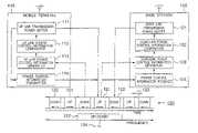
- FIG. 1is a block diagram showing an outline of the construction of the mobile communication system according to this embodiment.
- the mobile communication system of this embodimenthas the base station 100 which includes a down link transmission power setter 101 , a down link power control information comparator 102 , a down link power control information generator 103 and a power control information receiver 104 , the mobile terminal 110 which includes an up link transmission power setter 111 , an up link power control information comparator 112 , an up link power control information generator 113 and a power control information transmitter 114 , communication channels 120 which include an up link 121 , a down link 122 and guard times 123 , and a carrier frequency 124 .
- the base station 100 and the mobile terminal 110are connected by the up link 121 on which a signal is transmitted from the mobile terminal 110 to the base station 100 and the down link 122 on which a signal is transmitted from the base station 100 to the mobile terminal 110 .
- the communication channels 120 on the carrier frequency 124are assigned in a time-sharing manner to the up link 121 and down link 122 between which the guard times 123 are provided to prevent the interference.
- the down link transmission power setter 101 of the base station 100responds to the result from the down link power control information comparator 102 to fix a transmission power that is to be transmitted on the down link 122 from the base station 100 .
- the down link power control information comparator 102 of the base station 100compares whether or not the control information of down link 122 which is generated by the down link power control information generator 103 is larger than the maximum permissible compensation value of the base station 100 .
- the down link power control information generator 103generates power control information for the down link 122 by using the signal information on the up link 121 and the power control information of the down link sent from the mobile terminal 110 .
- the down link power control information generator 103 of the base station 100computes the value of the signal on the up link 121 before compensation by use of the power control information transmitted from the mobile terminal 110 , and generates the power control information for the down link 122 .
- the power control information receiver 104 of the base station 100receives the power control information transmitted from the mobile terminal 110 .
- the up link transmission power setter 111 of the mobile terminal 110determines the transmission power which the mobile terminal 110 is to transmit on the up link 121 in accordance with the result from the up link power control information comparator 112 .
- the up link power control information comparator 112 of the mobile terminal 110compares whether or not the control information of the up link 121 which is generated by the up link power control information generator 113 is larger than the maximum permissible compensation value of the mobile terminal 110 .
- the up link power control information generator 113 of the mobile terminal 110generates the power control information of the up link 121 by use of the signal information on the down link 122 .
- the power control information transmitter 114 of the mobile terminal 110transmits the power control information of the up link 121 set by the up link transmission power setter 111 to the base station 100 .
- FIG. 2is a block diagram showing an outline of the construction of the base station 100 of the mobile communication system according to this embodiment.
- the base station 100further includes a CPU 201 , a memory 202 , a display unit 203 , an input/output unit 204 , the digital signal processor (DSP) 205 , a mobile communication exchange interface unit 206 , an antenna 210 , a pilot channel modulator 211 , an answering channel modulator 212 , a transmission channel modulator 213 , reservation channel matched filters 214 – 215 , transmission channel matched filters 216 – 217 , a para-noise code generator (PN code generator) 218 , adders 220 and 221 , multipliers 230 and 231 , and a TDD switch 240 .
- PN code generatorpara-noise code generator
- a busconnects the CPU 201 that controls the operation of the whole base station 100 , the memory 202 that loads a control program for controlling the operation of the whole base station 100 , the display unit 203 that displays the operating condition of the base station 100 , the input/output unit 204 that instructs the base station 100 to operate for the input/output process, the DSP 205 that controls the process for communicating with the mobile terminal 110 , and the mobile communication exchange interface unit 206 .
- the base station 100communicates with the mobile terminal 110 by means of TDD-SS. Between the base station 100 and the mobile terminal 110 , there are provided a pilot channel, a reservation channel, an answering (responding) channel and a transmission channel on the same carrier frequency 124 (see FIG. 4 ).
- the DSP 205 of the base station 100includes the down link transmission power setter 101 , the down link power control information comparator 102 , the down link power control information generator 103 and the power control information receiver 104 as described above.
- the DSP 205is connected to the pilot channel modulator 211 , the answering channel modulator 212 , the transmission channel modulator 213 , the reservation channel matched filters 214 – 215 , the transmission channel matched filters 216 – 217 , the PN code generator 218 , and the TDD switch 240 .
- the pilot channel modulator 211 of the base station 100modulates the pilot channel for the transmission of the pilot signal, and supplies the modulated pilot signal through the adder 220 , multiplier 230 and TDD switch 240 to the antenna 210 , from which it is transmitted to the mobile terminal 110 .
- the answering channel modulator 212modulates the answering channel through which an answer or response to the reservation packet received from the mobile terminal 110 is transmitted.
- the modulated answer to the reservation packetis supplied through the adders 220 and 221 , multiplier 230 and TDD switch 240 to the antenna 210 , from which it is transmitted to the mobile terminal 110 .
- the transmission channel modulator 213modulates a plurality of transmission channels on which data packets are transmitted.
- the modulated data packetis supplied through the adders 220 and 221 , multiplier 230 and TDD switch 240 to the antenna 210 , from which it is transmitted to the mobile terminal 110 .
- the reservation channel matched filters 214 – 215receive the reservation packets transmitted from the mobile terminal 110 , and the received reservation packets are processed by the DSP 205 .
- the transmission channel matched filters 216 – 217receive the data packets sent from the mobile terminal 110 , and the received data packets are processed by the DSP 205 .
- the PN code generator 218generates the PN code that is used on each of the pilot channel, reservation channel, answering channel and transmission channel.
- the TDD switch 240responds to a TDD timing signal produced from the DSP 205 to timely switch the up link 121 and down link 122 , or to timely change over from transmission to reception or vice versa.
- the base station 100receives the power control information from the mobile terminal 110 , it supplies the received power control information through the reservation channel matched filters 214 – 215 and transmission channel matched filters 216 – 217 to the power control information receiver 104 of the DSP 205 .
- the power control signal fixed by the down link transmission power setter 101 of the DSP 205is supplied to the pilot channel modulator 211 , answering channel modulator 212 and transmission channel modulator 213 .
- FIG. 3shows in block diagram an outline of the construction of the mobile terminal 110 of the mobile communication system according to this embodiment.
- the mobile terminal 110further has a CPU 301 , a memory 302 , a display unit 303 , an input/output unit 304 , the DSP 305 , an antenna 310 , a reservation channel modulator 311 , a transmission channel modulator 312 , a pilot channel demodulator 313 , an answering channel demodulator 314 , a transmission channel demodulator 315 , a PN code generator 316 , a fading-compensating power controller 317 , an adder 320 , multipliers 330 and 331 , and a TDD switch 340 .
- the CPU 301 that controls the operation of the whole terminalis connected to the memory 302 that loads a control program, the display unit 303 that displays the condition of the operation, the input/output unit 304 that makes the input/output process on the data to transmit or have received, and the DSP 305 that controls the process for communicating with the base station 100 .
- the DSP 305 of the mobile terminal 110includes the up link transmission power setter 111 , the up link power control information comparator 112 , the up link power control information generator 113 and the power control information transmitter 114 as described above.
- the DSP 305is connected via a bus to the reservation channel modulator 311 , transmission channel modulator 312 , pilot channel demodulator 313 , answering channel demodulator 314 , transmission channel demodulator 315 , PN code generator 316 , fading-compensating power controller 317 , and TDD switch 340 .
- the reservation channel modulator 311modulates the reservation channel through which a notice of reservation for a transmission channel is sent to the base station 100 , informing the base station of having data packets to be transmitted through the transmission channel.
- the transmission channel modulator 312modulates a plurality of transmission channels on which data packets are transmitted.
- the reservation packets and data packetswhich have been modulated by the reservation channel modulator 311 and transmission channel modulator 312 , respectively, are supplied through the adder 320 , multiplier 330 , fading-compensating power controller 317 and TDD switch 340 to the antenna 310 , from which those packets are transmitted from the antenna to the base station 100 .
- the pilot channel demodulator 313demodulates the pilot channel on which a pilot signal is transmitted.
- the signal intensity and TDD timing of the received and demodulated pilot signalare supplied to the DSP 305 .
- the answering channel demodulator 314demodulates the answering channel on which answering packets are transmitted.
- the transmission channel demodulator 315demodulates a plurality of transmission channels on which data packets are transmitted.
- the PN code generator 316generates a plurality of PN codes to be used on each of the pilot channel, reservation channel, answering channel and transmission channel.
- the fading-compensating power controller 317controls the transmission power on the basis of the fading information produced from the DSP 305 .
- the TDD switch 340responds to a TDD timing signal produced from the DSP 305 to timely switch the up link 121 and down link 122 , or to timely change over from transmission to reception or vice versa.
- FIG. 4is a timing chart schematically showing the data transmission in the mobile communication system according to this embodiment.
- reference numerals 401 – 403represent the reservation packets, 411 – 413 the answering packets, 421 – 423 the data packets, and 431 and 432 the pilot data.
- the data that are transmitted and received in the mobile communication systemcontain the reservation packets 401 – 403 , answering packets 411 – 413 , data packets 421 – 423 , and pilot data 431 and 432 .
- the base station 100sends the answering packets 411 – 413 to the mobile terminal 110 , and then the mobile terminal 110 transmits the data packets 421 – 423 to the base station 100 .
- the reservation packets 401 – 403 , answering packets 411 – 413 , data packets 421 – 423 and pilot data 431 and 432 transmitted and received in the mobile communication system according to this embodimentare spread in their spectra in the form of the reservation code, answering code, up/down transmission code and pilot code, respectively, and transmitted on both up link 121 and down link 122 of the same carrier frequency 124 .
- the channels using the carrier frequency 124are separated as up link 121 and down link 122 in a time sharing manner.
- the reservation packets 401 – 403are first transmitted on the up link 121 from the mobile terminal 110 to the base station 100 .
- the base station 100 that received the reservation packets 401 – 403determines a transmission channel to be assigned to the mobile terminal 110 , and then transmits the answering packets 411 – 413 on the down link 122 to the mobile terminal 110 .
- the mobile terminal 110 that received the answering packets 411 – 413transmits the data packets 421 – 423 to the base station 100 .
- the pilot signal to be transmitted from the base station 100 to the mobile terminal 110is transmitted only on the down link 122 as, the pilot data 431 and 432 are assigned thereto.
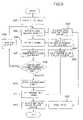
- FIG. 5shows the procedure of the process for the transmission power control in the base station 100 of the mobile communication system according to this embodiment.
- the base station 100makes transmission power control so that the transmission power on the down link 122 is determined on the basis of the power control information sent from the mobile terminal 110 and the signal intensity on the up link 121 , and transmitted to the mobile terminal 110 .
- the signal on the reservation channel or transmission channelis received from the reservation channel matched filters 214 – 215 or transmission channel matched filters 216 – 217 .
- the down link power control information generator 103 of the DSP 205 of the base station 100extracts the intensity from the input signal on the reservation channel or transmission channel at each bit.
- the down link power control information generator 103 of the base station 100estimates the fading of the up link 121 by using the power control information of the mobile terminal 110 received by the power control information receiver 104 and the previously received signal intensity at each bit on the reservation channel or transmission channel.
- the received signal intensity on the reservation channel or transmission channel of the up link 121is restored to the previous signal intensity before the compensation by the mobile terminal 110 by use of the information on the fading within the power control information transmitted from the mobile terminal 110 , and then the fading on the up link 121 is estimated.
- the down link power control information generator 103 of the base station 100computes the transmission power necessary for compensating for the fading that has been estimated at step 503 .
- the down link power control information comparator 102 of the base station 100compares the necessary power computed by the down link power control information generator 103 and the maximum permissible compensation value of the transmission power which can be compensated for by the base station 100 .
- step 505if the transmission power necessary for compensating for the fading estimated at step 503 is larger than the maximum permissible compensation value of the base station 100 as a result of the comparison between the necessary power computed by the down link power control information generator 103 and the maximum permissible compensation value of the base station 100 , the program goes to step 506 .
- step 506the base station 100 stops until the following slot, and then the program goes back to the step 502 .
- step 505if the transmission power necessary for compensating for the fading estimated at step 503 is equal to or lower than the maximum permissible compensation value of the base station 100 as a result of the comparison between the necessary power calculated by the down link power control information generator 103 and the maximum permissible compensation value of the base station 100 , the program goes to step 507 .
- the down link transmission power setter 101 of the base station 100fixes the transmission power on the down link 122 according to the necessary power calculated by the down link power control information generator 103 .
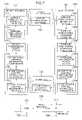
- FIG. 6shows the procedure of the process for the transmission power control in the mobile terminal 110 of the mobile communication system according to this embodiment.
- the mobile terminal 110makes transmission power control so as to set the transmission power on the up link 121 by receiving the pilot signal sent from the base station 100 , and to transmit to the base station 100 the power control information used to control the transmission power.
- the pilot signal transmitted from the base station 100is received by the pilot channel demodulator 313 and fed to the DSP 305 .
- the up link power control information generator 113 of the mobile terminal 110extracts the signal intensity from the received pilot signal.
- the up link power control information generator 113 of the mobile terminal 110integrates the extracted signal intensity over the particular time slot period in which the received pilot signal is transmitted or over the particular packet period in which the packet is sent.
- the up link power control information generator 113 of the mobile terminal 110computes the attenuation of the pilot signal due to the distance or the shadowing attenuation of the pilot signal due to obstacles along the channel from the integrated value over the slot or packet period.
- the up link power control information generator 113 of the mobile terminal 110computes the compensation value for use in the compensation for the attenuation calculated at step 604 .
- the up link power control information generator 113 of the mobile terminal 110estimates the fading caused in the pilot signal from the signal intensity at each bit of the pilot signal extracted at step 602 .
- the up link power control information generator 113 of the mobile terminal 110calculates the compensation value for use in compensating for the fading estimated at step 606 .
- the up link power control information comparator 112 of the mobile terminal 110compares the transmission power necessary to compensate for the fading calculated by the up link power control information generator 113 , and the maximum permissible compensation value of the maximum transmission power which can be compensated for by the mobile terminal 110 .
- step 608if the transmission power necessary to compensate for the fading estimated at step 607 is larger than the maximum permissible compensation value of the mobile terminal 100 as a result of the comparison between the necessary power calculated by the up link power control information generator 113 and the maximum permissible compensation value of the mobile terminal 110 , the program goes to step 609 .
- step 609the mobile terminal 110 stops until the following slot, and then the program goes back to step 602 .
- step 608if the transmission power necessary to correct the fading estimated at step 607 is equal to or smaller than the maximum permissible compensation value of the mobile terminal 100 as a result of the comparison between the necessary power calculated by the up link power control information generator 113 and the maximum permissible compensation value of the mobile terminal 110 , the program goes to step 610 .
- the up link transmission power setter 111 of the mobile terminal 110selects a transmission power level nearest to the necessary power calculated by the up link power control information generator 113 from a plurality of previously set transmission power levels.
- the up link transmission power setter 111 of the mobile terminal 110sets the transmission power on the up link 121 in accordance with the compensation value for use in compensating for the distance or shadowing attenuation which was calculated at step 605 and the transmission power level selected at step 610 .
- the up link power control information generator 113 of the mobile terminal 110measures the ratio C/I from the integrated value obtained when the pilot signal was integrated over the slot or packet period at step 603 .
- the power control information transmitter 114 of the mobile terminal 110sends the information of fading set at step 611 and the ratio C/I obtained at step 612 as power control information to the base station 100 .
- FIGS. 7 to 9Another embodiment of the mobile communication system using FDD to which the invention is applied will be described with reference to FIGS. 7 to 9 .
- the FDD mobile communication systemincludes a base station 700 which has a down link power control information receiver 701 , a down link transmission power setter 702 , an up link power control information generator 703 and an up link power control information transmitter 704 , a mobile terminal 710 which has a down link power control information transmitter 711 , a down link power control information generator 712 , an up link transmission power setter 713 and an up link power control information receiver 714 , an up link 721 , a down link 722 , a guard frequency 723 , an up link carrier frequency 724 , and a down link carrier frequency 725 .
- the base station 700 and the mobile terminal 710are connected by the up link 721 for transmitting a signal from the mobile terminal 710 to the base station 700 , and the down link 722 for transmitting a signal from the base station 700 to the mobile terminal 710 .
- the up link 721 and down link 722utilize different carrier frequencies, or the up link carrier frequency 724 and the down link carrier frequency 725 , respectively, with the guard frequency band 723 provided between the channels in order to prevent the interference.
- the mobile terminal 710When the base station 700 sends a pilot signal on the down link 722 , the mobile terminal 710 receives the pilot signal, and causes the down link power control information generator 712 to measure the intensity of the received pilot signal on the down link and to thereby estimate the attenuation of the signal and fading condition in the transmission path. Thus, it generates down link power control information for use in controlling the transmission power in the down link 722 .
- the down link power control information transmitter 711 of the mobile terminal 710transmits the generated down link power control information through the up link 721 to the base station 700 .
- the down link power control information receiver 701 of the base station 700receives the down link power control information sent from the mobile terminal 710 , and supplies it to the down link transmission power setter 702 .
- the down link transmission power setter 702 of the base station 700sets the transmission power of the down link 722 by using the received down link power control information.
- the up link power control information generator 703 of the base station 700when receiving the signal on the up link 721 from the mobile terminal 710 , measures the condition of fading or the like of the signal on the up link 721 , and generates up link power control information for use in controlling the transmission power of the up link 721 .
- the power control information transmitter 704 of the base station 700transmits the generated up link power control information through the down link 722 to the mobile terminal 710 .
- the up link power control information receiver 714 of the mobile terminal 710receives the up link power control information sent from the base station 700 , and supplies it to the up link transmission power setter 713 .
- the up link transmission power setter 713sets the transmission power of the up link 721 by using the received up link power control information.
- FIG. 8shows the procedure of the process for the transmission power control in the base station 700 of the mobile communication system.
- the base station 700makes transmission power control so that the transmission power of the down link 722 is set according to the down link power control information sent from the mobile terminal 710 , and that the condition of the fading or the like on the up link 721 is measured, thus producing up link power control information, which is transmitted to the mobile terminal 710 .
- the down link power control information receiver 701 of the base station 700receives the down link power control information sent from the mobile terminal 710 through the up link 721 .
- the down link transmission power setter 702 of the base station 700calculates the necessary transmission power by using the down link power control information sent from the mobile terminal 710 .
- the down link power control information comparator 706 of the base station 700compares the transmission power necessary for use in compensating for the necessary power that is generated by the down link power control information generator 705 , and the maximum permissible compensation value of the maximum transmission power that can be compensated for in the base station 700 .
- step 802 Aif the necessary transmission power calculated on the basis of the down link power control information is larger than the maximum permissible compensation value of the base station 700 as a result of the comparison, the program goes to step 802 B for stopping the transmission. After the transmission is stopped until the next slot or packet period, the program goes to step 804 , where the signal from the matched filter is received. On the other hand, if the calculated necessary transmission power is equal to or smaller than the maximum permissible compensation value of the base station 700 , the program goes to step 803 , where the transmission power is set.
- the down link transmission power setter 702 of the base station 700sets the transmission power of the down link 722 by using the calculated necessary transmission power.
- the up link power control information generator 703 of the base station 700receives the signal sent on the up link 721 from the mobile terminal 710 .
- the up link power control information generator 703 of the base station 700extracts the signal intensity at each bit from the received signal on the up link 721 .
- the up link power control information generator 703 of the base station 700estimates the fading of the signal sent on the up link 721 from the mobile terminal 710 on the basis of the change of the signal intensity extracted at each bit, and generates up link power control information.
- the up link power control information transmitter 704 of the base station 700transmits the up link power control information, which the up link power control information generator 703 has generated, through the down link 722 to the mobile terminal 710 .
- FIG. 9shows the procedure of the process for the transmission power control in the mobile terminal 710 of the mobile communication system according to this latter embodiment.
- the mobile terminal 710makes transmission power control so that the transmission power of the up link 721 is set according to the up link power control information sent from the base station 700 , and that the condition of the fading or the like of the signal on the down link 722 is measured, thus generating down link power control information, which is sent to the base station 700 .
- the mobile terminal 710receives the pilot signal sent on the down link 722 from the base station 700 .
- the up link transmission power setter 713 of the mobile terminal 710extracts the signal intensity at each bit from the received pilot signal.
- the up link transmission power setter 713 of the mobile terminal 710integrates the extracted signal intensity over a particular time, namely, a time slot for which data is transmitted, or a packet period for which a packet is transmitted.
- the up link transmission power setter 713 of the mobile terminal 710calculates the. attenuation of the pilot signal due to the distance or the shadowing attenuation due to the obstacles along the transmission path on the basis of the integrated value over the slot or packet period.
- the up link power control information receiver 714 of the mobile terminal 710extracts information of the attenuation due to the distance or shadowing from the received up link power control information.
- the up link transmission setter 713 of the mobile terminal 710computes a necessary transmission power of the signal to be sent on the up link 721 on the basis of the attenuation of the pilot signal due to the distance or the attenuation of the pilot signal due to the obstacles which- has been calculated at step 904 , and the information of the attenuation due to the distance or shadowing which has been extracted at step 905 .
- the up link power control information comparator 716 of the mobile terminal 710compares the transmission power calculated for compensation by the up link power control information generator with the maximum permissible compensation value of the maximum transmission power that can be compensated for in the mobile terminal 710 .
- step 906 Aif the transmission power calculates at step 906 and necessary to compensate for the attenuation which is the result of the steps 904 , 905 is larger than the maximum permissible compensation value of the mobile terminal 710 when the necessary power calculated by the up link power control information generator 715 is compared with the maximum permissible compensation value of the mobile terminal 710 , the program goes to step 906 B.
- step 906 Bthe mobile terminal 710 stops until the next slot or packet period, and then the program goes to step 908 , where the fading is estimated.
- step 906 Aif the necessary power calculated by the up link power control information generator is equal to or smaller than the maximum permissible compensation value of the mobile terminal 710 , the program goes to step 907 , where the transmission power is set.
- the up link transmission power setter 713 of the mobile terminal 710sets the above-calculated transmission power of the up link 721 .
- the down link power control information generator 712 of the mobile terminal 710estimates the fading in the down link 722 by using the signal intensity extracted at each bit from the pilot signal at step 902 , and the distance or shadowing attenuation calculated at step 904 .
- the down link power control information generator 712 of the mobile terminal 710measures the ratio C/I (Carrier/Interference) from the integrated value that was attained by integration over the slot or packet period of the pilot signal at step 903 .
- the down link power control information transmitter 711 of the mobile terminal 710transmits the information of fading estimated at step 908 and the ratio C/I obtained at step 909 as the down link power control information on the up link 721 .
- the power control information of the up link 721 which has been obtained in the base station 700is transmitted to the mobile terminal 710 in order for the mobile terminal 710 to control the transmission power of the up link 721
- the power control information of the down link 722 which has been attained in the mobile terminal 710is transmitted to the base station 700 in order for the base station 700 to control the transmission power of the down link 722 .
- the maximum permissible compensation value in the above comparing processcan be dynamically set in accordance with the condition of the communication path, for example, the velocity of the mobile terminal.
- the maximum permissible compensation valuefurther can be set in accordance with the difference between the data rates of the communication packets or the service quality needed.
Landscapes
- Engineering & Computer Science (AREA)
- Computer Networks & Wireless Communication (AREA)
- Signal Processing (AREA)
- Mobile Radio Communication Systems (AREA)
Abstract
Description
Claims (10)
Priority Applications (4)
| Application Number | Priority Date | Filing Date | Title |
|---|---|---|---|
| US10/376,310US7120457B2 (en) | 1996-11-27 | 2003-03-03 | Transmission control method and apparatus for mobile communication system |
| US11/544,655US7421283B2 (en) | 1996-11-27 | 2006-10-10 | Transmission power control method and apparatus for mobile communication system |
| US12/198,918US20090005107A1 (en) | 1996-11-27 | 2008-08-27 | Transmission power control system and apparatus for mobile communication system |
| US12/198,913US20090005106A1 (en) | 1996-11-27 | 2008-08-27 | Transmission power control method and apparatus for mobile communication system |
Applications Claiming Priority (5)
| Application Number | Priority Date | Filing Date | Title |
|---|---|---|---|
| JP31623296 | 1996-11-27 | ||
| JP08-316232 | 1996-11-27 | ||
| US08/975,672US6175744B1 (en) | 1996-11-27 | 1997-11-28 | Transmission power control method and apparatus for mobile communication system |
| US09/729,272US6546260B2 (en) | 1996-11-27 | 2000-12-05 | Transmission power control method and apparatus for mobile communication system |
| US10/376,310US7120457B2 (en) | 1996-11-27 | 2003-03-03 | Transmission control method and apparatus for mobile communication system |
Related Parent Applications (1)
| Application Number | Title | Priority Date | Filing Date |
|---|---|---|---|
| US09/729,272ContinuationUS6546260B2 (en) | 1996-11-27 | 2000-12-05 | Transmission power control method and apparatus for mobile communication system |
Related Child Applications (1)
| Application Number | Title | Priority Date | Filing Date |
|---|---|---|---|
| US11/544,655ContinuationUS7421283B2 (en) | 1996-11-27 | 2006-10-10 | Transmission power control method and apparatus for mobile communication system |
Publications (2)
| Publication Number | Publication Date |
|---|---|
| US20030130004A1 US20030130004A1 (en) | 2003-07-10 |
| US7120457B2true US7120457B2 (en) | 2006-10-10 |
Family
ID=18074792
Family Applications (6)
| Application Number | Title | Priority Date | Filing Date |
|---|---|---|---|
| US08/975,672Expired - LifetimeUS6175744B1 (en) | 1996-11-27 | 1997-11-28 | Transmission power control method and apparatus for mobile communication system |
| US09/729,272Expired - LifetimeUS6546260B2 (en) | 1996-11-27 | 2000-12-05 | Transmission power control method and apparatus for mobile communication system |
| US10/376,310Expired - Fee RelatedUS7120457B2 (en) | 1996-11-27 | 2003-03-03 | Transmission control method and apparatus for mobile communication system |
| US11/544,655Expired - Fee RelatedUS7421283B2 (en) | 1996-11-27 | 2006-10-10 | Transmission power control method and apparatus for mobile communication system |
| US12/198,918AbandonedUS20090005107A1 (en) | 1996-11-27 | 2008-08-27 | Transmission power control system and apparatus for mobile communication system |
| US12/198,913AbandonedUS20090005106A1 (en) | 1996-11-27 | 2008-08-27 | Transmission power control method and apparatus for mobile communication system |
Family Applications Before (2)
| Application Number | Title | Priority Date | Filing Date |
|---|---|---|---|
| US08/975,672Expired - LifetimeUS6175744B1 (en) | 1996-11-27 | 1997-11-28 | Transmission power control method and apparatus for mobile communication system |
| US09/729,272Expired - LifetimeUS6546260B2 (en) | 1996-11-27 | 2000-12-05 | Transmission power control method and apparatus for mobile communication system |
Family Applications After (3)
| Application Number | Title | Priority Date | Filing Date |
|---|---|---|---|
| US11/544,655Expired - Fee RelatedUS7421283B2 (en) | 1996-11-27 | 2006-10-10 | Transmission power control method and apparatus for mobile communication system |
| US12/198,918AbandonedUS20090005107A1 (en) | 1996-11-27 | 2008-08-27 | Transmission power control system and apparatus for mobile communication system |
| US12/198,913AbandonedUS20090005106A1 (en) | 1996-11-27 | 2008-08-27 | Transmission power control method and apparatus for mobile communication system |
Country Status (5)
| Country | Link |
|---|---|
| US (6) | US6175744B1 (en) |
| KR (2) | KR100496528B1 (en) |
| CN (2) | CN1136741C (en) |
| FI (1) | FI116112B (en) |
| SE (1) | SE521599C2 (en) |
Families Citing this family (63)
| Publication number | Priority date | Publication date | Assignee | Title |
|---|---|---|---|---|
| US6977967B1 (en)* | 1995-03-31 | 2005-12-20 | Qualcomm Incorporated | Method and apparatus for performing fast power control in a mobile communication system |
| TW347616B (en)* | 1995-03-31 | 1998-12-11 | Qualcomm Inc | Method and apparatus for performing fast power control in a mobile communication system a method and apparatus for controlling transmission power in a mobile communication system is disclosed. |
| CN1136741C (en)* | 1996-11-27 | 2004-01-28 | 株式会社日立制作所 | Transmission power control method for mobile communication system, mobile terminal and base station |
| US6351458B2 (en)* | 1997-09-22 | 2002-02-26 | Matsushita Electric Industrial Co., Ltd. | CDMA cellular wireless communication system |
| US6335920B1 (en)* | 1998-06-29 | 2002-01-01 | Hughes Electronics Corporation | Satellite-based measurement for uplink power control and time synchronization |
| KR20000013025A (en)* | 1998-08-01 | 2000-03-06 | 윤종용 | Forward initial transmitting power control device of telecommunication system and method therefor |
| JP3204310B2 (en)* | 1998-08-12 | 2001-09-04 | 日本電気株式会社 | CDMA mobile communication system and downlink transmission power control method thereof |
| US7158490B1 (en)* | 1998-09-21 | 2007-01-02 | Nokia Mobile Phones Limited | Apparatus, and associated method, for effectuating power control of a communication device |
| DE69935715T2 (en)* | 1999-01-16 | 2007-12-27 | Koninklijke Philips Electronics N.V. | RADIO COMMUNICATION SYSTEM |
| US6456835B1 (en)* | 1999-01-19 | 2002-09-24 | Tantivy Communications, Inc. | Arbitration method for high power transmissions in a code division multiple access system |
| FI112012B (en)* | 1999-01-19 | 2003-10-15 | Nokia Corp | Control of transmission power in a radio system |
| KR100401191B1 (en)* | 1999-02-13 | 2003-10-10 | 삼성전자주식회사 | Apparatus and method for controlling transmission of reverse link in cdma comminication system |
| KR100609122B1 (en)* | 1999-06-15 | 2006-08-04 | 에스케이 텔레콤주식회사 | Transmission power control apparatus and method thereof in code division multiple access system |
| GB9921989D0 (en)* | 1999-09-16 | 1999-11-17 | Nokia Telecommunications Oy | Power control in a communication system |
| US7310529B1 (en)* | 2000-01-24 | 2007-12-18 | Nortel Networks Limited | Packet data traffic control for cellular wireless networks |
| US20010040877A1 (en)* | 2000-05-09 | 2001-11-15 | Motorola, Inc. | Method of dynamic transmit scheduling using channel quality feedback |
| KR100659199B1 (en)* | 2000-05-19 | 2006-12-19 | 유티스타콤코리아 유한회사 | Transmission Power Control Circuit and Method of CDM Mobile Communication System |
| JP2001346265A (en)* | 2000-06-06 | 2001-12-14 | Matsushita Electric Ind Co Ltd | Wireless communication system and communication terminal device used therefor |
| GB0022633D0 (en)* | 2000-09-15 | 2000-11-01 | Koninkl Philips Electronics Nv | Secondary station and method of operating the station |
| JP3562459B2 (en)* | 2000-10-17 | 2004-09-08 | 株式会社日立製作所 | Mobile terminal device |
| US6999430B2 (en)* | 2000-11-30 | 2006-02-14 | Qualcomm Incorporated | Method and apparatus for transmitting data traffic on a wireless communication channel |
| US6748196B2 (en)* | 2001-01-30 | 2004-06-08 | Kon-Hee Lee | Transmit output controlling circuit and method of a wireless mobile communication system |
| US8199696B2 (en)* | 2001-03-29 | 2012-06-12 | Qualcomm Incorporated | Method and apparatus for power control in a wireless communication system |
| KR100434042B1 (en)* | 2001-05-19 | 2004-06-04 | 엘지전자 주식회사 | Closed loop power control method for code division multiple access |
| FR2825540B1 (en)* | 2001-06-01 | 2003-08-29 | Nortel Networks Ltd | METHOD FOR CONTROLLING TRANSMIT POWER OF A MOBILE RADIO TERMINAL, MOBILE TERMINAL AND BASE STATION FOR CARRYING OUT SAID METHOD |
| US7330446B2 (en)* | 2001-09-21 | 2008-02-12 | Industrial Technology Research Institute | Closed-loop power control method for a code-division multiple-access cellular system |
| JP3487508B2 (en)* | 2001-11-01 | 2004-01-19 | ソニー株式会社 | Communication device, communication method, communication control program, receiving device, receiving method, and receiving control program |
| KR100487221B1 (en)* | 2001-11-23 | 2005-05-03 | 삼성전자주식회사 | Method and apparatus for controlling the transmission power of control information in a mobile communication system |
| KR100446521B1 (en)* | 2001-12-12 | 2004-09-04 | 삼성전자주식회사 | Apparatus for measuring transmission power in a base station transceiver subsystem |
| KR100446526B1 (en)* | 2001-12-12 | 2004-09-04 | 삼성전자주식회사 | Apparatus for measuring transmission power in a base station transceiver subsystem |
| JP4155740B2 (en)* | 2002-01-11 | 2008-09-24 | 株式会社日立コミュニケーションテクノロジー | Radio power transmission terminal transmission power control method and base station therefor |
| JP4065138B2 (en)* | 2002-03-20 | 2008-03-19 | 松下電器産業株式会社 | Method for controlling generation of transmission power control information and mobile terminal device |
| US7170876B2 (en)* | 2002-04-30 | 2007-01-30 | Qualcomm, Inc. | Outer-loop scheduling design for communication systems with channel quality feedback mechanisms |
| EP1517456A4 (en)* | 2002-06-25 | 2009-12-30 | Fujitsu Ltd | PERFORMANCE RULES AND DEVICE |
| JP2004228762A (en)* | 2003-01-21 | 2004-08-12 | Matsushita Electric Ind Co Ltd | Test device, mobile terminal device, and test method |
| KR100976463B1 (en)* | 2003-02-04 | 2010-08-18 | 엘지전자 주식회사 | Method for controlling transmit power of uplink signal and communication terminal for same |
| GB0310289D0 (en)* | 2003-05-03 | 2003-06-11 | Koninkl Philips Electronics Nv | Communication system |
| EP1652048A4 (en) | 2003-07-21 | 2009-04-15 | Fusionone Inc | Device message management system |
| JP2005064751A (en)* | 2003-08-08 | 2005-03-10 | Matsushita Electric Ind Co Ltd | Mobile station apparatus and reception method in mobile station apparatus |
| US8290527B2 (en)* | 2004-07-30 | 2012-10-16 | Airvana, Corp. | Power control in a local network node (LNN) |
| US7328047B2 (en)* | 2004-08-31 | 2008-02-05 | Research In Motion Limited | Mobile wireless communications device with reduced interfering energy from the display and related methods |
| US7606210B2 (en) | 2004-09-10 | 2009-10-20 | Nivis, Llc | System and method for message consolidation in a mesh network |
| US7554941B2 (en)* | 2004-09-10 | 2009-06-30 | Nivis, Llc | System and method for a wireless mesh network |
| US7505734B2 (en)* | 2004-09-10 | 2009-03-17 | Nivis, Llc | System and method for communicating broadcast messages in a mesh network |
| US7676195B2 (en)* | 2004-09-10 | 2010-03-09 | Nivis, Llc | System and method for communicating messages in a mesh network |
| KR100663492B1 (en)* | 2004-10-26 | 2007-01-02 | 삼성전자주식회사 | Power control method and apparatus for portable internet terminal |
| JP4656387B2 (en)* | 2004-12-28 | 2011-03-23 | 日本電気株式会社 | Mobile radio communication system and monitoring control method in mobile radio communication system |
| JP4551814B2 (en)* | 2005-05-16 | 2010-09-29 | Okiセミコンダクタ株式会社 | Wireless communication device |
| CN101218763B (en)* | 2005-06-14 | 2012-02-15 | 株式会社Ntt都科摩 | Base station, mobile station, and power control method |
| JP4834352B2 (en) | 2005-06-14 | 2011-12-14 | 株式会社エヌ・ティ・ティ・ドコモ | Base station, mobile station, and power control method |
| JP2007013489A (en)* | 2005-06-29 | 2007-01-18 | Kyocera Corp | COMMUNICATION SYSTEM, COMMUNICATION DEVICE, TRANSMISSION POWER CONTROL METHOD, AND PROGRAM |
| US7893873B2 (en)* | 2005-12-20 | 2011-02-22 | Qualcomm Incorporated | Methods and systems for providing enhanced position location in wireless communications |
| JP4317992B2 (en)* | 2006-02-28 | 2009-08-19 | 沖電気工業株式会社 | Communication control device, communication control method, node, and communication system |
| JP5057105B2 (en)* | 2006-03-17 | 2012-10-24 | 日本電気株式会社 | Transmission power control method, base station, base station control station, and control program therefor |
| JP4763539B2 (en)* | 2006-07-21 | 2011-08-31 | 富士通株式会社 | Wireless system, wireless transmitter and wireless receiver |
| US20080221388A1 (en)* | 2007-03-09 | 2008-09-11 | University Of Washington | Side viewing optical fiber endoscope |
| US8811891B2 (en)* | 2007-06-29 | 2014-08-19 | Samsung Electronics Co., Ltd. | Apparatus and method for setting transmit power of a compact base station in a wireless communication system |
| CN101971662B (en)* | 2008-01-30 | 2014-07-23 | 爱立信电话股份有限公司 | Method and device for configuring measurement time slots for mobile terminals in TDD system |
| US9474099B2 (en)* | 2008-12-23 | 2016-10-18 | Keyssa, Inc. | Smart connectors and associated communications links |
| KR101568878B1 (en) | 2009-03-17 | 2015-11-12 | 삼성전자주식회사 | Method and apparatus for reporting available transmit power information of a terminal in a wireless communication system |
| US9681394B2 (en)* | 2012-02-28 | 2017-06-13 | Optis Circuit Technology, Llc | Method for power control, user equipment, computer program and storage medium |
| US10419958B2 (en)* | 2014-04-25 | 2019-09-17 | Nec Corporation | Wireless communication control method and device in wireless communication control system, and wireless communication device |
| US10616835B2 (en) | 2016-06-02 | 2020-04-07 | Lg Electronics Inc. | Method for controlling uplink transmission power in wireless communication system, and apparatus therefor |
Citations (41)
| Publication number | Priority date | Publication date | Assignee | Title |
|---|---|---|---|---|
| JPS56117441A (en) | 1980-02-22 | 1981-09-14 | Omron Tateisi Electronics Co | Suppressing method for undesired electric wave in information collecting system |
| JPS60182228A (en) | 1984-02-29 | 1985-09-17 | Nippon Telegr & Teleph Corp <Ntt> | wireless telephone equipment |
| JPS63184420A (en) | 1986-09-04 | 1988-07-29 | Nippon Telegr & Teleph Corp <Ntt> | Signal transmission system in mobile communication |
| JPS6442944A (en) | 1987-08-10 | 1989-02-15 | Mitsubishi Electric Corp | Packet communication equipment with variable coding rate |
| US4811421A (en) | 1986-03-14 | 1989-03-07 | Christophe Havel | Transmission power control device in a radio communication transmitting/receiving station |
| JPH01174023A (en) | 1987-12-28 | 1989-07-10 | Nippon Telegr & Teleph Corp <Ntt> | Mobile communication system |
| JPH02184149A (en) | 1989-01-11 | 1990-07-18 | Iwatsu Electric Co Ltd | cordless telephone device |
| US5093924A (en)* | 1989-09-19 | 1992-03-03 | Nippon Telegraph And Telephone Corporation | Channel assigning method in a mobile communication system |
| JPH0530001A (en) | 1991-07-19 | 1993-02-05 | Mitsubishi Electric Corp | Cordless telephone system |
| EP0548939A2 (en) | 1991-12-26 | 1993-06-30 | Nec Corporation | Transmission power control system capable of keeping signal quality constant in mobile communication network |
| US5267262A (en) | 1989-11-07 | 1993-11-30 | Qualcomm Incorporated | Transmitter power control system |
| US5282239A (en) | 1991-07-09 | 1994-01-25 | Mitsubishi Denki Kabushiki Kaisha | Cordless telephone system for moving conveyances |
| US5333175A (en) | 1993-01-28 | 1994-07-26 | Bell Communications Research, Inc. | Method and apparatus for dynamic power control in TDMA portable radio systems |
| JPH07212303A (en) | 1994-01-12 | 1995-08-11 | Hitachi Ltd | Power control method |
| JPH07221700A (en) | 1994-01-31 | 1995-08-18 | Matsushita Electric Ind Co Ltd | CDMA / TDD wireless communication system |
| EP0682419A2 (en) | 1994-05-12 | 1995-11-15 | Ntt Mobile Communications Network Inc. | Transmission power control for mobile radio using open and closed loop |
| US5485486A (en) | 1989-11-07 | 1996-01-16 | Qualcomm Incorporated | Method and apparatus for controlling transmission power in a CDMA cellular mobile telephone system |
| JPH0865201A (en) | 1994-08-18 | 1996-03-08 | Matsushita Electric Ind Co Ltd | Mobile communication device |
| US5535429A (en) | 1993-01-27 | 1996-07-09 | Telefonaktiebolaget Lm Ericsson | Method of disconnecting an established communication connection in a mobile radio system |
| US5539728A (en) | 1993-12-02 | 1996-07-23 | Cselt - Centro Studi E Laboratori Telecomunicazioni S.P.A. | Method and device for power control in the base-to-mobile link of a mobile radio system with code division multiple access |
| JPH08242198A (en) | 1995-03-02 | 1996-09-17 | Nec Corp | Packet communication method |
| US5559789A (en) | 1994-01-31 | 1996-09-24 | Matsushita Electric Industrial Co., Ltd. | CDMA/TDD Radio Communication System |
| US5559790A (en) | 1993-07-23 | 1996-09-24 | Hitachi, Ltd. | Spread spectrum communication system and transmission power control method therefor |
| US5574984A (en) | 1993-02-11 | 1996-11-12 | Motorola, Inc. | Method and apparatus for controlling a power level of a base station of a wireless communication system |
| US5604730A (en) | 1994-07-25 | 1997-02-18 | Qualcomm Incorporated | Remote transmitter power control in a contention based multiple access system |
| KR970055914A (en) | 1995-12-26 | 1997-07-31 | 김광호 | Automatic Power Control Method in Mobile Wireless System |
| US5655219A (en)* | 1993-03-05 | 1997-08-05 | Hitachi, Ltd. | Wireless LAN system capable of re-transmission under management of a base station device to a destination mobile terminal device |
| US5673259A (en)* | 1995-05-17 | 1997-09-30 | Qualcomm Incorporated | Random access communications channel for data services |
| JPH09331291A (en) | 1996-04-10 | 1997-12-22 | Oki Electric Ind Co Ltd | Radio communication system and radio communication equipment |
| US5713074A (en) | 1994-08-11 | 1998-01-27 | Roke Manor Research Limited | Mobile radio power control device using the comparison of retransmitted data |
| JPH10215219A (en) | 1996-11-27 | 1998-08-11 | Hitachi Ltd | Mobile communication system transmission power control method and its implementation device |
| US5839056A (en) | 1995-08-31 | 1998-11-17 | Nokia Telecommunications Oy | Method and apparatus for controlling transmission power of a radio transmitter |
| US5845212A (en) | 1995-10-11 | 1998-12-01 | Nec Corporation | Optimum power and handover control by cellular system mobile unit |
| US5864760A (en) | 1993-10-28 | 1999-01-26 | Qualcomm Incorporated | Method and apparatus for reducing the average transmit power from a sectorized base station |
| US5870393A (en) | 1995-01-20 | 1999-02-09 | Hitachi, Ltd. | Spread spectrum communication system and transmission power control method therefor |
| US5873027A (en) | 1993-07-16 | 1999-02-16 | Matsushita Electric Industrial Co., Ltd. | Mobile radio system with control over radio wave output if a malfunction is detected |
| US5987033A (en)* | 1997-09-08 | 1999-11-16 | Lucent Technologies, Inc. | Wireless lan with enhanced capture provision |
| US6175744B1 (en) | 1996-11-27 | 2001-01-16 | Hitachi, Ltd. | Transmission power control method and apparatus for mobile communication system |
| US6330456B1 (en)* | 1998-12-11 | 2001-12-11 | Nortel Networks Limited | System and method to combine power control commands during soft handoff in DS/CDMA cellular systems |
| US6377813B1 (en)* | 1998-12-03 | 2002-04-23 | Nokia Corporation | Forward link closed loop power control for a third generation wideband CDMA system |
| US6526032B1 (en)* | 1998-05-08 | 2003-02-25 | Matsushita Electric Industrial Co., Ltd. | Base station apparatus and transmission power control method |
Family Cites Families (20)
| Publication number | Priority date | Publication date | Assignee | Title |
|---|---|---|---|---|
| US559789A (en)* | 1896-05-05 | Trustees | ||
| JPS6421521A (en) | 1987-07-15 | 1989-01-24 | Nec Corp | Coordinate input device |
| JPS6442944U (en) | 1987-09-11 | 1989-03-15 | ||
| KR970005591B1 (en) | 1992-11-06 | 1997-04-18 | 삼성항공산업 주식회사 | Auto zoom camera and its driving method |
| JPH06334588A (en)* | 1993-05-25 | 1994-12-02 | Nec Corp | System and device for mobile radio station communication |
| JPH07226709A (en)* | 1994-02-14 | 1995-08-22 | Matsushita Electric Ind Co Ltd | Wireless communication system |
| JP2993554B2 (en)* | 1994-05-12 | 1999-12-20 | エヌ・ティ・ティ移動通信網株式会社 | Transmission power control method and communication device using the transmission power control method |
| US5603096A (en)* | 1994-07-11 | 1997-02-11 | Qualcomm Incorporated | Reverse link, closed loop power control in a code division multiple access system |
| JP3104537B2 (en) | 1994-08-30 | 2000-10-30 | 松下電器産業株式会社 | Electronic components |
| JP2910619B2 (en)* | 1995-05-22 | 1999-06-23 | 日本電気株式会社 | Wireless transmission power cutoff method |
| ZA965340B (en)* | 1995-06-30 | 1997-01-27 | Interdigital Tech Corp | Code division multiple access (cdma) communication system |
| US5802445A (en)* | 1995-07-13 | 1998-09-01 | Globalstar L.P. | Methods and apparatus for providing user RF exposure monitoring and control in a satellite communications system |
| JP3212238B2 (en) | 1995-08-10 | 2001-09-25 | 株式会社日立製作所 | Mobile communication system and mobile terminal device |
| CA2206385C (en)* | 1996-05-28 | 2009-03-24 | Shinichiro Ohmi | Access control method in communication system |
| US5864547A (en) | 1996-08-21 | 1999-01-26 | Hughes Electronics Corporation | Method and system for controlling uplink power in a high data rate satellite communication system employing on-board demodulation and remodulation |
| EP0940930B1 (en)* | 1998-03-03 | 2012-09-26 | NEC Corporation | Method of controlling transmission power in a cellular type mobile communication system |
| JP3403950B2 (en)* | 1998-09-07 | 2003-05-06 | 松下電器産業株式会社 | Mobile station apparatus, broadcast channel receiving method in mobile station apparatus, and cell search method in mobile station apparatus |
| KR100401191B1 (en)* | 1999-02-13 | 2003-10-10 | 삼성전자주식회사 | Apparatus and method for controlling transmission of reverse link in cdma comminication system |
| KR100464485B1 (en)* | 2000-11-09 | 2004-12-31 | 엘지전자 주식회사 | A method and a device of transmitting high-speed packet data |
| US7330446B2 (en)* | 2001-09-21 | 2008-02-12 | Industrial Technology Research Institute | Closed-loop power control method for a code-division multiple-access cellular system |
- 1997
- 1997-11-26CNCNB971229538Apatent/CN1136741C/ennot_activeExpired - Lifetime
- 1997-11-26CNCNB2003101245879Apatent/CN1242633C/ennot_activeExpired - Lifetime
- 1997-11-26SESE9704345Apatent/SE521599C2/ennot_activeIP Right Cessation
- 1997-11-26KRKR1019970063161Apatent/KR100496528B1/ennot_activeExpired - Lifetime
- 1997-11-26FIFI974336Apatent/FI116112B/ennot_activeIP Right Cessation
- 1997-11-28USUS08/975,672patent/US6175744B1/ennot_activeExpired - Lifetime
- 2000
- 2000-12-05USUS09/729,272patent/US6546260B2/ennot_activeExpired - Lifetime
- 2002
- 2002-04-09KRKR1020020019119Apatent/KR100473252B1/ennot_activeExpired - Lifetime
- 2003
- 2003-03-03USUS10/376,310patent/US7120457B2/ennot_activeExpired - Fee Related
- 2006
- 2006-10-10USUS11/544,655patent/US7421283B2/ennot_activeExpired - Fee Related
- 2008
- 2008-08-27USUS12/198,918patent/US20090005107A1/ennot_activeAbandoned
- 2008-08-27USUS12/198,913patent/US20090005106A1/ennot_activeAbandoned
Patent Citations (43)
| Publication number | Priority date | Publication date | Assignee | Title |
|---|---|---|---|---|
| JPS56117441A (en) | 1980-02-22 | 1981-09-14 | Omron Tateisi Electronics Co | Suppressing method for undesired electric wave in information collecting system |
| JPS60182228A (en) | 1984-02-29 | 1985-09-17 | Nippon Telegr & Teleph Corp <Ntt> | wireless telephone equipment |
| US4811421A (en) | 1986-03-14 | 1989-03-07 | Christophe Havel | Transmission power control device in a radio communication transmitting/receiving station |
| JPS63184420A (en) | 1986-09-04 | 1988-07-29 | Nippon Telegr & Teleph Corp <Ntt> | Signal transmission system in mobile communication |
| JPS6442944A (en) | 1987-08-10 | 1989-02-15 | Mitsubishi Electric Corp | Packet communication equipment with variable coding rate |
| JPH01174023A (en) | 1987-12-28 | 1989-07-10 | Nippon Telegr & Teleph Corp <Ntt> | Mobile communication system |
| JPH02184149A (en) | 1989-01-11 | 1990-07-18 | Iwatsu Electric Co Ltd | cordless telephone device |
| US5093924A (en)* | 1989-09-19 | 1992-03-03 | Nippon Telegraph And Telephone Corporation | Channel assigning method in a mobile communication system |
| US5267262A (en) | 1989-11-07 | 1993-11-30 | Qualcomm Incorporated | Transmitter power control system |
| US5485486A (en) | 1989-11-07 | 1996-01-16 | Qualcomm Incorporated | Method and apparatus for controlling transmission power in a CDMA cellular mobile telephone system |
| US5282239A (en) | 1991-07-09 | 1994-01-25 | Mitsubishi Denki Kabushiki Kaisha | Cordless telephone system for moving conveyances |
| JPH0530001A (en) | 1991-07-19 | 1993-02-05 | Mitsubishi Electric Corp | Cordless telephone system |
| EP0548939A2 (en) | 1991-12-26 | 1993-06-30 | Nec Corporation | Transmission power control system capable of keeping signal quality constant in mobile communication network |
| US5535429A (en) | 1993-01-27 | 1996-07-09 | Telefonaktiebolaget Lm Ericsson | Method of disconnecting an established communication connection in a mobile radio system |
| US5333175A (en) | 1993-01-28 | 1994-07-26 | Bell Communications Research, Inc. | Method and apparatus for dynamic power control in TDMA portable radio systems |
| US5574984A (en) | 1993-02-11 | 1996-11-12 | Motorola, Inc. | Method and apparatus for controlling a power level of a base station of a wireless communication system |
| US5655219A (en)* | 1993-03-05 | 1997-08-05 | Hitachi, Ltd. | Wireless LAN system capable of re-transmission under management of a base station device to a destination mobile terminal device |
| US5873027A (en) | 1993-07-16 | 1999-02-16 | Matsushita Electric Industrial Co., Ltd. | Mobile radio system with control over radio wave output if a malfunction is detected |
| US5559790A (en) | 1993-07-23 | 1996-09-24 | Hitachi, Ltd. | Spread spectrum communication system and transmission power control method therefor |
| US5864760A (en) | 1993-10-28 | 1999-01-26 | Qualcomm Incorporated | Method and apparatus for reducing the average transmit power from a sectorized base station |
| US5539728A (en) | 1993-12-02 | 1996-07-23 | Cselt - Centro Studi E Laboratori Telecomunicazioni S.P.A. | Method and device for power control in the base-to-mobile link of a mobile radio system with code division multiple access |
| JPH07212303A (en) | 1994-01-12 | 1995-08-11 | Hitachi Ltd | Power control method |
| JPH07221700A (en) | 1994-01-31 | 1995-08-18 | Matsushita Electric Ind Co Ltd | CDMA / TDD wireless communication system |
| US5559789A (en) | 1994-01-31 | 1996-09-24 | Matsushita Electric Industrial Co., Ltd. | CDMA/TDD Radio Communication System |
| US5590409A (en) | 1994-05-12 | 1996-12-31 | Ntt Mobile Communications Network Inc. | Transmission power control method and a transmission power control apparatus |
| EP0682419A2 (en) | 1994-05-12 | 1995-11-15 | Ntt Mobile Communications Network Inc. | Transmission power control for mobile radio using open and closed loop |
| US5604730A (en) | 1994-07-25 | 1997-02-18 | Qualcomm Incorporated | Remote transmitter power control in a contention based multiple access system |
| US5713074A (en) | 1994-08-11 | 1998-01-27 | Roke Manor Research Limited | Mobile radio power control device using the comparison of retransmitted data |
| JPH0865201A (en) | 1994-08-18 | 1996-03-08 | Matsushita Electric Ind Co Ltd | Mobile communication device |
| US5870393A (en) | 1995-01-20 | 1999-02-09 | Hitachi, Ltd. | Spread spectrum communication system and transmission power control method therefor |
| JPH08242198A (en) | 1995-03-02 | 1996-09-17 | Nec Corp | Packet communication method |
| US5673259A (en)* | 1995-05-17 | 1997-09-30 | Qualcomm Incorporated | Random access communications channel for data services |
| US5839056A (en) | 1995-08-31 | 1998-11-17 | Nokia Telecommunications Oy | Method and apparatus for controlling transmission power of a radio transmitter |
| US5845212A (en) | 1995-10-11 | 1998-12-01 | Nec Corporation | Optimum power and handover control by cellular system mobile unit |
| KR970055914A (en) | 1995-12-26 | 1997-07-31 | 김광호 | Automatic Power Control Method in Mobile Wireless System |
| US6031828A (en) | 1996-04-10 | 2000-02-29 | Oki Electric Industry Co., Ltd | Radio communication system |
| JPH09331291A (en) | 1996-04-10 | 1997-12-22 | Oki Electric Ind Co Ltd | Radio communication system and radio communication equipment |
| JPH10215219A (en) | 1996-11-27 | 1998-08-11 | Hitachi Ltd | Mobile communication system transmission power control method and its implementation device |
| US6175744B1 (en) | 1996-11-27 | 2001-01-16 | Hitachi, Ltd. | Transmission power control method and apparatus for mobile communication system |
| US5987033A (en)* | 1997-09-08 | 1999-11-16 | Lucent Technologies, Inc. | Wireless lan with enhanced capture provision |
| US6526032B1 (en)* | 1998-05-08 | 2003-02-25 | Matsushita Electric Industrial Co., Ltd. | Base station apparatus and transmission power control method |
| US6377813B1 (en)* | 1998-12-03 | 2002-04-23 | Nokia Corporation | Forward link closed loop power control for a third generation wideband CDMA system |
| US6330456B1 (en)* | 1998-12-11 | 2001-12-11 | Nortel Networks Limited | System and method to combine power control commands during soft handoff in DS/CDMA cellular systems |
Non-Patent Citations (4)
| Title |
|---|
| Japanese Office Action mailed Dec. 14, 2004. |
| Japanese Patent Office Action, JP-2002-068405 with mailing date of Jun. 8, 2004. |
| Japanese Patent Office Action, JP-9 325096 with mailing date of Jun. 8, 2004. |
| Korean Patent Office Action with issue date of Mar. 26, 2004. |
Also Published As
| Publication number | Publication date |
|---|---|
| US20090005106A1 (en) | 2009-01-01 |
| SE9704345L (en) | 1998-05-28 |
| US20010000168A1 (en) | 2001-04-05 |
| US20090005107A1 (en) | 2009-01-01 |
| FI974336A0 (en) | 1997-11-26 |
| CN1136741C (en) | 2004-01-28 |
| US20030130004A1 (en) | 2003-07-10 |
| KR100496528B1 (en) | 2005-09-30 |
| CN1185084A (en) | 1998-06-17 |
| US6175744B1 (en) | 2001-01-16 |
| SE521599C2 (en) | 2003-11-18 |
| KR100473252B1 (en) | 2005-03-08 |
| SE9704345D0 (en) | 1997-11-26 |
| FI974336L (en) | 1998-05-28 |
| US7421283B2 (en) | 2008-09-02 |
| US20070032197A1 (en) | 2007-02-08 |
| US6546260B2 (en) | 2003-04-08 |
| FI116112B (en) | 2005-09-15 |
| CN1510938A (en) | 2004-07-07 |
| CN1242633C (en) | 2006-02-15 |
| KR19980042787A (en) | 1998-08-17 |
Similar Documents
| Publication | Publication Date | Title |
|---|---|---|
| US7120457B2 (en) | Transmission control method and apparatus for mobile communication system | |
| EP0680160B1 (en) | Method and apparatus for transmission power control of a mobile station during soft handoff in a CDMA system | |
| US7953029B2 (en) | Mobile communication system with transmission control of data transmission rate request value | |
| US6272354B1 (en) | Method for adjusting transmit power during call set-up, and a cellular radio system | |
| EP0928075B1 (en) | Transmission power control in a CDMA/TDD radio communication system | |
| EP1117195B1 (en) | Base and mobile station apparatus and transmission power control method | |
| US6954434B2 (en) | CDMA mobile communication system and transmission power control method therefor | |
| US5771451A (en) | Method of transmission power control in a cellular mobile communication system and apparatus thereof | |
| US7532888B2 (en) | CDMA mobile communication system, base station, mobile station and communication control method during soft handover | |
| CA2402370C (en) | Mcs selection in downlink shared channel transmission | |
| US6501954B2 (en) | Mobile radio communication system and radio circuit controlling method therefor | |
| EP1045527A1 (en) | Communication system and apparatus with transmission power control | |
| EP1133070A2 (en) | Transmit power control method and apparatus in a radio communication system | |
| EP1134913A2 (en) | Mobile station, base station and mobile communication system with transmission power control | |
| JP3631601B2 (en) | Mobile communication system transmission power control method and apparatus for implementing the same | |
| US6097947A (en) | Method for detecting failure mobile station in cellular mobile communication network through transmission power control | |
| US6081727A (en) | Transmission power control system capable of disabling communication of a mobile terminal which carries out an abnormal operation | |
| US6718181B1 (en) | Communication terminal, and over-interference prevention method | |
| EP0999657B1 (en) | CDMA transmission power control capable of preventing call disconnection and degradation of capacity of subscribers | |
| JP3902775B2 (en) | Implementation apparatus for mobile communication system and recording medium recording its processing program | |
| JP3660911B2 (en) | Mobile communication system transmission power control method, apparatus for implementing the same, and computer-readable recording medium recording the processing program |
Legal Events
| Date | Code | Title | Description |
|---|---|---|---|
| FEPP | Fee payment procedure | Free format text:PAYOR NUMBER ASSIGNED (ORIGINAL EVENT CODE: ASPN); ENTITY STATUS OF PATENT OWNER: LARGE ENTITY | |
| AS | Assignment | Owner name:HITACHI COMMUNICATION TECHNOLOGIES, LTD., JAPAN Free format text:ASSIGNMENT OF ASSIGNORS INTEREST;ASSIGNOR:HITACHI, LTD.;REEL/FRAME:020281/0435 Effective date:20071107 | |
| AS | Assignment | Owner name:HITACHI, LTD.,JAPAN Free format text:MERGER;ASSIGNOR:HITACHI COMMUNICATION TECHNOLOGIES, LTD.;REEL/FRAME:023758/0625 Effective date:20090701 Owner name:HITACHI, LTD., JAPAN Free format text:MERGER;ASSIGNOR:HITACHI COMMUNICATION TECHNOLOGIES, LTD.;REEL/FRAME:023758/0625 Effective date:20090701 | |
| AS | Assignment | Owner name:TENTLY LIMITED Free format text:ASSIGNMENT OF ASSIGNORS INTEREST;ASSIGNOR:HITACHI, LTD.;REEL/FRAME:024160/0438 Effective date:20100317 | |
| FPAY | Fee payment | Year of fee payment:4 | |
| FPAY | Fee payment | Year of fee payment:8 | |
| AS | Assignment | Owner name:FIPA FROHWITTER INTELLECTUAL PROPERTY AG, GERMANY Free format text:ASSIGNMENT OF ASSIGNORS INTEREST;ASSIGNOR:TENTLY LIMITED;REEL/FRAME:033534/0807 Effective date:20140616 | |
| FEPP | Fee payment procedure | Free format text:MAINTENANCE FEE REMINDER MAILED (ORIGINAL EVENT CODE: REM.) | |
| LAPS | Lapse for failure to pay maintenance fees | Free format text:PATENT EXPIRED FOR FAILURE TO PAY MAINTENANCE FEES (ORIGINAL EVENT CODE: EXP.); ENTITY STATUS OF PATENT OWNER: LARGE ENTITY | |
| STCH | Information on status: patent discontinuation | Free format text:PATENT EXPIRED DUE TO NONPAYMENT OF MAINTENANCE FEES UNDER 37 CFR 1.362 | |
| FP | Lapsed due to failure to pay maintenance fee | Effective date:20181010 |