US7120359B2 - Broadcast and select all optical network - Google Patents
Broadcast and select all optical networkDownload PDFInfo
- Publication number
- US7120359B2 US7120359B2US10/178,071US17807102AUS7120359B2US 7120359 B2US7120359 B2US 7120359B2US 17807102 AUS17807102 AUS 17807102AUS 7120359 B2US7120359 B2US 7120359B2
- Authority
- US
- United States
- Prior art keywords
- optical
- fiber ring
- add
- light
- signal
- Prior art date
- Legal status (The legal status is an assumption and is not a legal conclusion. Google has not performed a legal analysis and makes no representation as to the accuracy of the status listed.)
- Expired - Lifetime, expires
Links
- 230000003287optical effectEffects0.000titleclaimsabstractdescription344
- 239000000835fiberSubstances0.000claimsdescription124
- 238000000034methodMethods0.000claimsdescription28
- 230000004044responseEffects0.000claimsdescription11
- 238000004891communicationMethods0.000claimsdescription4
- 230000008878couplingEffects0.000claims1
- 238000010168coupling processMethods0.000claims1
- 238000005859coupling reactionMethods0.000claims1
- 230000001419dependent effectEffects0.000description16
- 239000013307optical fiberSubstances0.000description13
- 238000013459approachMethods0.000description9
- 238000006243chemical reactionMethods0.000description5
- 238000005516engineering processMethods0.000description5
- 239000000969carrierSubstances0.000description4
- 230000001427coherent effectEffects0.000description4
- 238000001514detection methodMethods0.000description4
- 238000010586diagramMethods0.000description4
- 230000003595spectral effectEffects0.000description4
- 230000008901benefitEffects0.000description3
- 230000005540biological transmissionEffects0.000description3
- 239000006185dispersionSubstances0.000description3
- 238000010276constructionMethods0.000description2
- 239000000284extractSubstances0.000description2
- RGNPBRKPHBKNKX-UHFFFAOYSA-NhexaflumuronChemical compoundC1=C(Cl)C(OC(F)(F)C(F)F)=C(Cl)C=C1NC(=O)NC(=O)C1=C(F)C=CC=C1FRGNPBRKPHBKNKX-UHFFFAOYSA-N0.000description2
- 230000007774longtermEffects0.000description2
- 229910003327LiNbO3Inorganic materials0.000description1
- 230000003044adaptive effectEffects0.000description1
- 230000003321amplificationEffects0.000description1
- 230000008859changeEffects0.000description1
- 238000013461designMethods0.000description1
- 230000009977dual effectEffects0.000description1
- 230000008030eliminationEffects0.000description1
- 238000003379elimination reactionMethods0.000description1
- 230000007613environmental effectEffects0.000description1
- GQYHUHYESMUTHG-UHFFFAOYSA-Nlithium niobateChemical compound[Li+].[O-][Nb](=O)=OGQYHUHYESMUTHG-UHFFFAOYSA-N0.000description1
- 238000012986modificationMethods0.000description1
- 230000004048modificationEffects0.000description1
- 230000009022nonlinear effectEffects0.000description1
- 238000003199nucleic acid amplification methodMethods0.000description1
- 230000010363phase shiftEffects0.000description1
- 230000009467reductionEffects0.000description1
- 238000000926separation methodMethods0.000description1
Images


Classifications
- H—ELECTRICITY
- H04—ELECTRIC COMMUNICATION TECHNIQUE
- H04Q—SELECTING
- H04Q11/00—Selecting arrangements for multiplex systems
- H04Q11/0001—Selecting arrangements for multiplex systems using optical switching
- H04Q11/0062—Network aspects
- G—PHYSICS
- G02—OPTICS
- G02F—OPTICAL DEVICES OR ARRANGEMENTS FOR THE CONTROL OF LIGHT BY MODIFICATION OF THE OPTICAL PROPERTIES OF THE MEDIA OF THE ELEMENTS INVOLVED THEREIN; NON-LINEAR OPTICS; FREQUENCY-CHANGING OF LIGHT; OPTICAL LOGIC ELEMENTS; OPTICAL ANALOGUE/DIGITAL CONVERTERS
- G02F1/00—Devices or arrangements for the control of the intensity, colour, phase, polarisation or direction of light arriving from an independent light source, e.g. switching, gating or modulating; Non-linear optics
- G02F1/01—Devices or arrangements for the control of the intensity, colour, phase, polarisation or direction of light arriving from an independent light source, e.g. switching, gating or modulating; Non-linear optics for the control of the intensity, phase, polarisation or colour
- G02F1/03—Devices or arrangements for the control of the intensity, colour, phase, polarisation or direction of light arriving from an independent light source, e.g. switching, gating or modulating; Non-linear optics for the control of the intensity, phase, polarisation or colour based on ceramics or electro-optical crystals, e.g. exhibiting Pockels effect or Kerr effect
- G02F1/035—Devices or arrangements for the control of the intensity, colour, phase, polarisation or direction of light arriving from an independent light source, e.g. switching, gating or modulating; Non-linear optics for the control of the intensity, phase, polarisation or colour based on ceramics or electro-optical crystals, e.g. exhibiting Pockels effect or Kerr effect in an optical waveguide structure
- G02F1/0356—Devices or arrangements for the control of the intensity, colour, phase, polarisation or direction of light arriving from an independent light source, e.g. switching, gating or modulating; Non-linear optics for the control of the intensity, phase, polarisation or colour based on ceramics or electro-optical crystals, e.g. exhibiting Pockels effect or Kerr effect in an optical waveguide structure controlled by a high-frequency electromagnetic wave component in an electric waveguide structure
- H—ELECTRICITY
- H04—ELECTRIC COMMUNICATION TECHNIQUE
- H04B—TRANSMISSION
- H04B10/00—Transmission systems employing electromagnetic waves other than radio-waves, e.g. infrared, visible or ultraviolet light, or employing corpuscular radiation, e.g. quantum communication
- H04B10/27—Arrangements for networking
- H04B10/275—Ring-type networks
- H04B10/2755—Ring-type networks with a headend
- H—ELECTRICITY
- H04—ELECTRIC COMMUNICATION TECHNIQUE
- H04B—TRANSMISSION
- H04B10/00—Transmission systems employing electromagnetic waves other than radio-waves, e.g. infrared, visible or ultraviolet light, or employing corpuscular radiation, e.g. quantum communication
- H04B10/50—Transmitters
- H04B10/501—Structural aspects
- H04B10/503—Laser transmitters
- H04B10/505—Laser transmitters using external modulation
- H—ELECTRICITY
- H04—ELECTRIC COMMUNICATION TECHNIQUE
- H04B—TRANSMISSION
- H04B10/00—Transmission systems employing electromagnetic waves other than radio-waves, e.g. infrared, visible or ultraviolet light, or employing corpuscular radiation, e.g. quantum communication
- H04B10/50—Transmitters
- H04B10/501—Structural aspects
- H04B10/506—Multiwavelength transmitters
- H—ELECTRICITY
- H04—ELECTRIC COMMUNICATION TECHNIQUE
- H04B—TRANSMISSION
- H04B10/00—Transmission systems employing electromagnetic waves other than radio-waves, e.g. infrared, visible or ultraviolet light, or employing corpuscular radiation, e.g. quantum communication
- H04B10/50—Transmitters
- H04B10/516—Details of coding or modulation
- H04B10/5165—Carrier suppressed; Single sideband; Double sideband or vestigial
- H—ELECTRICITY
- H04—ELECTRIC COMMUNICATION TECHNIQUE
- H04B—TRANSMISSION
- H04B10/00—Transmission systems employing electromagnetic waves other than radio-waves, e.g. infrared, visible or ultraviolet light, or employing corpuscular radiation, e.g. quantum communication
- H04B10/50—Transmitters
- H04B10/564—Power control
- H—ELECTRICITY
- H04—ELECTRIC COMMUNICATION TECHNIQUE
- H04J—MULTIPLEX COMMUNICATION
- H04J14/00—Optical multiplex systems
- H04J14/02—Wavelength-division multiplex systems
- H04J14/0201—Add-and-drop multiplexing
- H04J14/0202—Arrangements therefor
- H04J14/0204—Broadcast and select arrangements, e.g. with an optical splitter at the input before adding or dropping
- H—ELECTRICITY
- H04—ELECTRIC COMMUNICATION TECHNIQUE
- H04J—MULTIPLEX COMMUNICATION
- H04J14/00—Optical multiplex systems
- H04J14/02—Wavelength-division multiplex systems
- H04J14/0201—Add-and-drop multiplexing
- H04J14/0202—Arrangements therefor
- H04J14/0205—Select and combine arrangements, e.g. with an optical combiner at the output after adding or dropping
- H—ELECTRICITY
- H04—ELECTRIC COMMUNICATION TECHNIQUE
- H04J—MULTIPLEX COMMUNICATION
- H04J14/00—Optical multiplex systems
- H04J14/02—Wavelength-division multiplex systems
- H04J14/0201—Add-and-drop multiplexing
- H04J14/0202—Arrangements therefor
- H04J14/0206—Express channels arrangements
- H—ELECTRICITY
- H04—ELECTRIC COMMUNICATION TECHNIQUE
- H04J—MULTIPLEX COMMUNICATION
- H04J14/00—Optical multiplex systems
- H04J14/02—Wavelength-division multiplex systems
- H04J14/0201—Add-and-drop multiplexing
- H04J14/0202—Arrangements therefor
- H04J14/0209—Multi-stage arrangements, e.g. by cascading multiplexers or demultiplexers
- H—ELECTRICITY
- H04—ELECTRIC COMMUNICATION TECHNIQUE
- H04J—MULTIPLEX COMMUNICATION
- H04J14/00—Optical multiplex systems
- H04J14/02—Wavelength-division multiplex systems
- H04J14/0201—Add-and-drop multiplexing
- H04J14/0202—Arrangements therefor
- H04J14/021—Reconfigurable arrangements, e.g. reconfigurable optical add/drop multiplexers [ROADM] or tunable optical add/drop multiplexers [TOADM]
- H04J14/0212—Reconfigurable arrangements, e.g. reconfigurable optical add/drop multiplexers [ROADM] or tunable optical add/drop multiplexers [TOADM] using optical switches or wavelength selective switches [WSS]
- H—ELECTRICITY
- H04—ELECTRIC COMMUNICATION TECHNIQUE
- H04J—MULTIPLEX COMMUNICATION
- H04J14/00—Optical multiplex systems
- H04J14/02—Wavelength-division multiplex systems
- H04J14/0201—Add-and-drop multiplexing
- H04J14/0202—Arrangements therefor
- H04J14/021—Reconfigurable arrangements, e.g. reconfigurable optical add/drop multiplexers [ROADM] or tunable optical add/drop multiplexers [TOADM]
- H04J14/02126—Multicast switch arrangements
- H—ELECTRICITY
- H04—ELECTRIC COMMUNICATION TECHNIQUE
- H04J—MULTIPLEX COMMUNICATION
- H04J14/00—Optical multiplex systems
- H04J14/02—Wavelength-division multiplex systems
- H04J14/0201—Add-and-drop multiplexing
- H04J14/0202—Arrangements therefor
- H04J14/0213—Groups of channels or wave bands arrangements
- H—ELECTRICITY
- H04—ELECTRIC COMMUNICATION TECHNIQUE
- H04J—MULTIPLEX COMMUNICATION
- H04J14/00—Optical multiplex systems
- H04J14/02—Wavelength-division multiplex systems
- H04J14/0201—Add-and-drop multiplexing
- H04J14/0215—Architecture aspects
- H04J14/0217—Multi-degree architectures, e.g. having a connection degree greater than two
- H—ELECTRICITY
- H04—ELECTRIC COMMUNICATION TECHNIQUE
- H04J—MULTIPLEX COMMUNICATION
- H04J14/00—Optical multiplex systems
- H04J14/02—Wavelength-division multiplex systems
- H04J14/0201—Add-and-drop multiplexing
- H04J14/0215—Architecture aspects
- H04J14/0219—Modular or upgradable architectures
- H—ELECTRICITY
- H04—ELECTRIC COMMUNICATION TECHNIQUE
- H04J—MULTIPLEX COMMUNICATION
- H04J14/00—Optical multiplex systems
- H04J14/02—Wavelength-division multiplex systems
- H04J14/0201—Add-and-drop multiplexing
- H04J14/0215—Architecture aspects
- H04J14/022—For interconnection of WDM optical networks
- H—ELECTRICITY
- H04—ELECTRIC COMMUNICATION TECHNIQUE
- H04J—MULTIPLEX COMMUNICATION
- H04J14/00—Optical multiplex systems
- H04J14/02—Wavelength-division multiplex systems
- H04J14/0227—Operation, administration, maintenance or provisioning [OAMP] of WDM networks, e.g. media access, routing or wavelength allocation
- H04J14/0228—Wavelength allocation for communications one-to-all, e.g. broadcasting wavelengths
- H—ELECTRICITY
- H04—ELECTRIC COMMUNICATION TECHNIQUE
- H04J—MULTIPLEX COMMUNICATION
- H04J14/00—Optical multiplex systems
- H04J14/02—Wavelength-division multiplex systems
- H04J14/0227—Operation, administration, maintenance or provisioning [OAMP] of WDM networks, e.g. media access, routing or wavelength allocation
- H04J14/0241—Wavelength allocation for communications one-to-one, e.g. unicasting wavelengths
- H—ELECTRICITY
- H04—ELECTRIC COMMUNICATION TECHNIQUE
- H04J—MULTIPLEX COMMUNICATION
- H04J14/00—Optical multiplex systems
- H04J14/02—Wavelength-division multiplex systems
- H04J14/0278—WDM optical network architectures
- H04J14/0283—WDM ring architectures
- H—ELECTRICITY
- H04—ELECTRIC COMMUNICATION TECHNIQUE
- H04J—MULTIPLEX COMMUNICATION
- H04J14/00—Optical multiplex systems
- H04J14/02—Wavelength-division multiplex systems
- H04J14/0287—Protection in WDM systems
- H04J14/0293—Optical channel protection
- H04J14/0294—Dedicated protection at the optical channel (1+1)
- H—ELECTRICITY
- H04—ELECTRIC COMMUNICATION TECHNIQUE
- H04J—MULTIPLEX COMMUNICATION
- H04J14/00—Optical multiplex systems
- H04J14/02—Wavelength-division multiplex systems
- H04J14/0287—Protection in WDM systems
- H04J14/0293—Optical channel protection
- H04J14/0295—Shared protection at the optical channel (1:1, n:m)
- G—PHYSICS
- G02—OPTICS
- G02F—OPTICAL DEVICES OR ARRANGEMENTS FOR THE CONTROL OF LIGHT BY MODIFICATION OF THE OPTICAL PROPERTIES OF THE MEDIA OF THE ELEMENTS INVOLVED THEREIN; NON-LINEAR OPTICS; FREQUENCY-CHANGING OF LIGHT; OPTICAL LOGIC ELEMENTS; OPTICAL ANALOGUE/DIGITAL CONVERTERS
- G02F1/00—Devices or arrangements for the control of the intensity, colour, phase, polarisation or direction of light arriving from an independent light source, e.g. switching, gating or modulating; Non-linear optics
- G02F1/01—Devices or arrangements for the control of the intensity, colour, phase, polarisation or direction of light arriving from an independent light source, e.g. switching, gating or modulating; Non-linear optics for the control of the intensity, phase, polarisation or colour
- G02F1/21—Devices or arrangements for the control of the intensity, colour, phase, polarisation or direction of light arriving from an independent light source, e.g. switching, gating or modulating; Non-linear optics for the control of the intensity, phase, polarisation or colour by interference
- G02F1/212—Mach-Zehnder type
- H—ELECTRICITY
- H04—ELECTRIC COMMUNICATION TECHNIQUE
- H04J—MULTIPLEX COMMUNICATION
- H04J14/00—Optical multiplex systems
- H04J14/02—Wavelength-division multiplex systems
- H04J14/0278—WDM optical network architectures
- H04J14/0286—WDM hierarchical architectures
- H—ELECTRICITY
- H04—ELECTRIC COMMUNICATION TECHNIQUE
- H04Q—SELECTING
- H04Q11/00—Selecting arrangements for multiplex systems
- H04Q11/0001—Selecting arrangements for multiplex systems using optical switching
- H04Q11/0005—Switch and router aspects
- H04Q2011/0037—Operation
- H04Q2011/0047—Broadcast; Multicast
- H—ELECTRICITY
- H04—ELECTRIC COMMUNICATION TECHNIQUE
- H04Q—SELECTING
- H04Q11/00—Selecting arrangements for multiplex systems
- H04Q11/0001—Selecting arrangements for multiplex systems using optical switching
- H04Q11/0062—Network aspects
- H04Q2011/009—Topology aspects
- H04Q2011/0092—Ring
Definitions
- the present inventionrelates generally to all optical networks, and more particularly to an all optical network that uses broadcast and select and minimizes pass-through losses between rings.
- regeneratorsIn today's long-haul dense-wavelength-division-multiplexed (DWDM) optical networks, multiple regenerators have been replaced by optical amplifiers.
- DWDMdense-wavelength-division-multiplexed
- telecom operatorsare still relying on regenerators and O-E-O wavelength-converters.
- Wavelength-convertersare needed because conventional DWDM systems do not possess enough wavelengths to cover a wide service area such as multiple interconnected rings, and therefore wavelengths used in one ring must be re-used in another ring via wavelength converters.
- Regeneratorsare needed because most of the transmission technologies used in today's metro networks can only support limited transmission distance and data rates.
- FIGS. 1( a ) and 1 ( b )have a central hub which terminates all the wavelengths by a pair of DWDM mux and demux, an array of O-E-O regenerators, and an electronic cross-connect/switch, such as the one illustrated in FIG. 2 . If the central hub in FIG. 2 does not terminate all the wavelengths by DWDM mux/demux and O-E-O regenerators, there is a possibility that the wavelengths may circulate perpetually around the ring especially when excessive amplifications are supplied along the ring. This positive net gain can cause lasing phenomenon and consequently unstable received signals.
- 6,192,173is that a controlled loss can be added to the ring, and the net round-trip loss should be large enough to prevent the onset of positive feedback but is sufficiently small to allow detection of optical signals to occur with a certain acceptable bit-error-rate.
- This methodmakes network control very complicated because adaptive loss control must be provided to different ring sizes and number of nodes, and the system bit-error-rate performance can be degraded.
- wavelength add-dropis carried out by using two optical circulators and a fiber Bragg grating (FBG).
- the FBGperforms the “drop” function by reflecting a wavelength through the first optical circulator. Consequently, when there are two or more wavelengths needed to be dropped, more FBGs are inserted between the two optical circulators, and service disruption is incurred.
- dynamic wavelength OADMis implemented in terms of wavelength separation and combination devices (e.g., a DWDM wavelength/band mux/demux pair), together with one or more optical switches—such as 2 ⁇ 2 or N ⁇ N devices.
- the mux and demux pairare connected back-to-back, while for those wavelengths or bands to be dropped and added, there is a 2 ⁇ 2 switch inserted between the mux/demux pair.
- a system plannerneeds to pre-plan how many 2 ⁇ 2 switches must be placed in advance. This results in two problems, (1) once a fixed number of 2 ⁇ 2 switches are installed, future upgrade to install more switches can cause service disruptions, and (2) if an N ⁇ N switch is installed right at the beginning to cover every possible wavelength/band add-drop in the future, its cost will be high. In addition, the N ⁇ N switch long-term reliability is still questionable.
- the added wavelengthcan be the same as the dropped wavelength. This is a useful feature for ring networks with limited number of available wavelengths.
- FIGS. 3( a ) and 3 ( b )Another type of optical ring network, illustrated in FIGS. 3( a ) and 3 ( b ), uses optical couplers along the main path of the ring network to replace the complicated OADMs.
- This kind of optical networkis a broadcast-and-select optical network, also referred to as a “one-hop” networks, which has been investigated in a DWDM all-optical star (R. Ramaswami and K. N. Sirarajan, Optical Networks:. a practical perspective , Morgan, 1998) and proposed in ring networks (“Flexible WDM network architecture”, U.S. Pat. No. 6,192,173, April 2001).
- any user on the ringcan receive this message (the “broadcast” characteristic of the network).
- a receiverreceives its desired signal by using either a tunable filter or a fixed filter/demultiplexer (the “select” characteristics of the receiver).
- a tunable lasercan also be used to launch a dynamically tunable wavelength into a fixed optical filter on the receiving end. In either case, the disadvantage is that no wavelength can be re-used. This is because the dropped wavelength will continue to propagate along the rest of the ring network(s), and no other nodes can use the dropped wavelength any more.
- each transceiver cardmust receive at a specific wavelength, ⁇ x , and transmit at another wavelength, ⁇ y .
- Most of today's metro-ring optical networkshave a limited number of available wavelengths, consequently one cannot afford not to “re-use” the “dropped” wavelengths. Therefore, today's DWDM metro-ring optical network seldom uses broadcast-and-select scheme.
- an object of the present inventionis to provide a broadcast and select architecture in an all optical fiber ring network.
- Another object of the present inventionis to provide a passive fiber ring network that does not have active elements.
- Yet another object of the present inventionis to provide an all optical fiber ring network that has minimal fiber ring lasing or coherent cross-talk on the ring.
- a further object of the present inventionis to provide an all optical fiber ring network that eliminates the need for in-line amplifier gain saturation on the ring.
- Still another object of the present inventionis to provide an all optical fiber ring network where all wavelength powers are equalized by controlling the launched power of each wavelength.
- a first ringis included that has at least one transmitter and one receiver.
- the first ringincludes a plurality of network nodes.
- At least a first add/drop broadband coupleris coupled to the first ring.
- the broadband couplerincludes an add port and a drop port to add and drop wavelengths to and or from the first ring, a pass-through direction and an add/drop direction.
- the first add/drop broadband coupleris configured to minimize a pass-through loss in the first ring and is positioned on the first ring.
- An all optical network for optical signal trafficincludes a first ring and at least a first add/drop broadband coupler.
- the first ringincludes least one transmitter and one receiver, a plurality of network nodes.
- the first add/drop broadband coupleris coupled to the first ring and is configured to minimize a pass-through loss in the first ring.
- the broadband coupleris positioned on the first ring and includes an add port and a drop port to add and drop wavelengths to and or from the first ring, a pass-through direction and an add/drop direction.
- the broadband couplerincludes at least a first 1 ⁇ 2 coupler to add traffic and a second 1 ⁇ 2 coupler to drop traffic.
- the first ringincludes at least a first working fiber and a first protection fiber that carries all of the optical signal traffic, wherein optical signal traffic travels in a clockwise direction in the first working fiber and in a counter-clockwise direction in the first protection fiber.
- an all-optical hubthat couples the first ring to at least a second ring.
- the all-optical hubincludes at least one 1 ⁇ N band-splitter and an N ⁇ 1 coupler that couples optical signal traffic among rings coupled together on the network, wherein N is the number of rings coupled together.
- a loss padthat maintains at least 25 dB round-trip traveling loss around the first ring.
- a first three-port add-drop filtercoupled to the first ring in the add/drop direction, the first three-port add-drop filter including an input port and a drop port.
- a plurality of wavelength-dependent three-port add-drop filtersconfigured to be cascaded at each node for the drop direction to drop multiple wavelengths, and cascaded for the add direction to add multiple wavelengths.
- a least a fist expansion modulecoupled to the first ring that adds and drops more than one wavelength.
- the tunable filteris configured to reflect non-selected wavelengths to a through port for one cascaded three-port optical add/drop filter to an adjacent cascaded three-port optical add/drop filter.
- FIG. 1( a )is a schematic diagram of the conventional OADM that is placed in the main path of the ring network for OADM using Bragg grating.
- FIG. 1( b )is a schematic diagram of the conventional OADM that is placed in the main path of the ring network for OADM using DWDM mux/demux and optical switches.
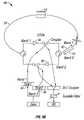
- FIG. 2illustrates a conventional central hub consisting of DWDM mux/demux and electronic N ⁇ N switches.
- FIG. 3( a )is a schematic diagram of a broadcast-and-select or “one hop” optical ring network using only optical couplers at each node.
- FIG. 3( b )is similar to FIG. 3( a ), except that there are in-line amplifiers inserted between add and drop ports.
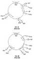
- FIG. 4( a )illustrates one embodiment of a wavelength-add-drop hierarchy.
- FIG. 4( b )illustrates another embodiment of a hierarchical wavelength add-drop.
- FIG. 5is a diagram of a conventional SONET uni-directional protection switching ring (UPSR).
- UPSRuni-directional protection switching ring
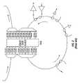
- FIG. 6illustrates one embodiment of a two-fiber broadcast-and-select ring architecture of the present invention, with a pair of 1 ⁇ 1, or 1 ⁇ 2 switches in the central hub.
- FIG. 7( a )illustrates operation of protection switches in the central hub and nodes of the FIG. 6 embodiment when both fibers break.
- FIG. 7( b )illustrates operation of protection switches in the central hub and nodes of the FIG. 6 embodiment when a single fiber breaks.
- FIG. 7( c )illustrates operation of protection switches in the central hub and nodes of the FIG. 6 embodiment when a single optical amplifier fails.
- FIG. 8illustrates operation of protection switches in the central hub and a node when a single optical amplifier fails.
- FIG. 10illustrates that multiple rings can be interconnected in a manner such that they appear to be a single ring.
- FIG. 11illustrates a central hub construction without O-E-O conversions for interconnecting two ring networks.
- FIG. 12illustrates an out-of-band optical supervision/communication channel at 1510 nm for inter-nodal communication and protection switching.
- FIG. 13illustrates a central hub construction without O-E-O conversions for interconnecting three ring networks.
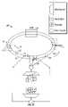
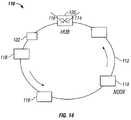
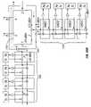
- FIG. 14illustrates one embodiment of a broadcast and select all optical network of the present invention.
- FIGS. 15( a ) through 15 ( f )illustrate various arrangements of an in-line amplifier, booster amplifier and optical fiber couplers in the various nodes that can be utilized with the all optical network of FIG. 14 .
- FIG. 16illustrates operation of protection switches in the central hub and nodes of the FIG. 14 embodiment when there is a break in a fiber.
- FIG. 17illustrates an embodiment of the FIG. 16 protection switches when there is no break in a fiber.
- FIG. 18illustrates a hub structure that can be utilized with the FIG. 14 embodiment.
- FIG. 19illustrates the FIG. 14 embodiment with three coupled rings.
- FIG. 20( a )illustrates the FIG. 14 embodiment as an all passive optical ring.
- FIG. 20( b )illustrates another embodiment of the FIG. 20( a ) all passive optical ring network.
- FIG. 20( c )illustrates another embodiment of the FIG. 20( a ) all passive optical ring network.
- FIG. 20( d )illustrates another embodiment of the FIG. 20( a ) all passive optical ring network.
- FIG. 21illustrates the FIG. 14 embodiment with series add/drop off-line.
- FIG. 22illustrates the FIG. 14 embodiment with parallel add/drop off-line.
- FIG. 23illustrates another embodiment of a FIG. 14 network with series add/drop off-line.
- An all optical networkis utilized with at least two rings that are geographically dispersed. Each ring has at least one transmitter and receiver. A sufficiently large enough number of wavelengths is shared in both rings to achieve the sharing without O-E-O conversions between the rings. Alternatively, the available wavelengths are separated into distinct ring bands.
- the optical signal trafficis shared throughout the entire optical network. Each ring is provided with its own distinct ring band of the optical signal traffic. All of the optical signal traffic is transmittable throughout the optical network.
- Each receiveris configured to receive only wavelengths in a ring band designated for its associated ring.
- the present inventionalso provides all optical networks for optical signal traffic.
- the all optical networkhas at least first and second rings. Each ring has at least one transmitter and receiver and its own distinct ring band of the optical signal traffic. All of the optical signal traffic is transmittable throughout the entire all optical network. Each receiver is configured to receive only wavelengths in a ring band designated for its associated ring.
- a central hubcouples the first and second rings and separates the optical signal traffic into ring bands.
- an all optical networkin another embodiment, includes a first ring with at least first and second protection fibers that carry all of the optical signal traffic.
- the optical signal traffictravels in a clockwise direction in the first protection fiber and in a counter-clockwise direction in the second protection fiber.
- At least one 1 ⁇ 1 or a 1 ⁇ 2 switchis coupled to each first and second protection fiber. The 1 ⁇ 1 or 1 ⁇ 2 switch is maintained in an open position when there is no break point in the ring and closed upon an occurrence of a break point in the ring.
- in-line amplifiersWith the methods and networks of the present invention, various arrangements of in-line amplifiers, booster amplifiers and optical fiber couplers in each node can be used, such as those illustrated by way of example and without limitation in FIGS. 4( a ) through ( c ).
- FIG. 4( a )illustrates one example of a wavelength-add-drop hierarchy.
- the ring networkonly broadband couplers, and possibly optical amplifiers, are used.
- an array of tunable lasersare added through an optical coupler.
- a fixed wavelength demultiplexer or an optical filtersis located after a main-path coupler.
- an optional 1 ⁇ M optical splitter and M tunable optical filterscan be included. Each is utilized to extract a sub-wavelength channel.
- FIG. 4( b )illustrates another example of a hierarchical wavelength add-drop.
- the ring networkonly broadband couplers, and possibly optical amplifiers, are used.
- an array of N fixed lasersare added through a DWDM multiplexer, for a large N, through a CDWM multiplexer or an optical coupler for a small N.
- a tunable wavelength OADMis located after the main-path coupler.
- an optional 1 ⁇ N optical splitter and N tunable optical filtersare optional 1 ⁇ N optical splitter and N tunable optical filters. These extract a sub-wavelength channel.
- FIG. 5is included to illustrate a conventional SONET uni-directional protection switching ring (UPSR) that can be used with the methods and networks of the present invention.
- UPSRuni-directional protection switching ring
- FIG. 6One embodiment of the present invention, illustrated in FIG. 6 , is an all optical network 10 with a first ring 12 that has at least first and second protection fibers 14 and 16 that carry all of the optical signal traffic of network 10 .
- Optical signal traffictravels in a clockwise direction 18 in first protection fiber 14 and in a counter-clockwise direction 20 in second protection fiber 16 .
- At least one 1 ⁇ 1 or 1 ⁇ 2 switch 22is coupled to first and second protection fibers 14 and 16 in a central hub 24 or at any nodes 26 of network 10 .
- Switch 22is open under normal conditions and a break point is maintained in ring 12 . A perpetual re-circulating of optical signal traffic is prevented.
- Each nodeincludes one or more transmitters and receivers, mux/demux and fiber coupler.
- Every transmitter in network 10launches its signal in both first and second fibers 14 and 16 . Because of the break point in central hub 24 only one of these duplicated signals can be received at a destination. The break point in central hub 24 also prevents the two duplicated signals arriving at the same destination in which case the two signals may be combined destructively, they may be 180° out of phase.
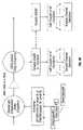
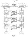
- FIG. 7( a )When there is a broken fiber in network 10 , as shown in FIG. 7( a ), a new break point is created. The old break point in hub 24 is immediately closed for both first and second protection fibers 14 and 16 . Several other fiber or optical amplifier break conditions can also be protected by turning on and off the pair of 1 ⁇ 1 switches, as illustrated in FIGS. 7( b ) through 7 ( c ).
- both first and second fibers 14 and 16are broken.
- optical switch 26is open to ensure that there is a break point in the clock-wise working ring.
- FIG. 8( c )a failure exists in one optical amplifier.
- Optical switches 28 and 30are switched in order to let launched signal bypass the failed in-line amplifier.
- Optical switch 32is switched to open position to ensure that there is a break point in the clock-wise ring. In a normal operating condition, without a break or failure of a fiber or an amplifier, the transmitted signal arrives at the receiver in direction 18 or direction 20 but not in both.
- FIG. 8In another embodiment of the present invention, illustrated in FIG. 8 only one switch 32 needs to be turned open to perform the same protection as that in FIG. 7( c ).
- a single fiber 34is used instead of dual fibers, as illustrated in FIGS. 9( a ) through ( e ).
- each nodehas two optical amplifiers 36 and 38 arranged in such a condition that each one amplifies a band of optical signals and is oriented toward opposite directions.
- the same datais duplicated in the two bands 40 and 42 by using either two optical transmitters 44 and 46 , as shown in FIGS. 9( a ), or by using a single transmitter 18 transmitting duplicated signals in different frequencies (wavelengths), as shown in FIG. 9 ( d ).
- the receiver in each nodecan select either of the two bands, which come from different directions along the ring, by using a tunable filter which can tune from one band to the other.
- Ring to ring interconnectioncan be achieved by breaking the rings and interconnecting them to form a single ring 50 , as illustrated in FIG. 10 .
- the FIG. 10 embodimentforces each in-line amplifier in each node to amplify all wavelengths traveling along the ring, even though the wavelengths were not intended for that particular node. This can increase the cost of optical amplifiers.
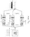
- all optical network 52 for optical signal trafficincludes at least first and second rings 54 and 56 .
- Each ring 30 and 32has at least one transmitter and one receiver and its own distinct ring band of the optical signal traffic. All of the optical signal traffic is transmittable throughout the entire all optical network 52 .
- Each receiveris configured to receive only wavelengths in a ring band designated for its associated ring 54 and 56 .
- a central hubcouples first and second rings 54 and 56 , and separates the optical signal traffic into the ring bands.
- some of the wavelengthscan be sent to a second ring without going back to the originating ring.
- the wavelength loading on each optical amplifiercan be alleviated.
- band 53is for intra-ring traffic and band 55 is for hub or intra-ring traffic.
- Ring bands 53 and 55can contain more than 200 wavelengths. Additionally, more than 200 wavelengths inside rings 54 and 56 can support both the wavelength-consuming broadcast-and-select architecture and long-term traffic growth.
- band 55travels inside one ring, while band 53 goes to the second ring.
- Each ring 54 and 56includes at least one 1 ⁇ 1 or 1 ⁇ 2 hub switch 58 and 60 , respectively. Switches 58 and 60 are controlled by a reserved out-of-band optical supervision channel (OSC).
- the OSCis a 1510 nm channel. The OSC channel travels along the entire ring 54 and 56 hop-by-hop, a illustrated in FIG. 12 .
- two C-band/1150 nm couplers 62 and 64are provided, one extracts the 1510 nm supervision signal from the ring and the other couples the 1510 nm supervision signal back to the ring. Consequently, 1510 nm supervision signals, which contain various control and management information, do not have to pass through an optical amplifier 66 . Because the out-of-band OSC channel monitors the operation status of both equipment and fiber in each ring node hop-by-hop, any fiber and/or amplifier break of network 52 can be immediately reported to a network manager based on the status of the OSC channel.
- First and second rings 54 and 56can be geographically dispersed or hierarchical rings.
- Rings 54 and 56can be the same as ring 12 and include first and a second protection fibers 14 and 16 , switch 22 and central hub 24 , with the optical signal traffic traveling in clockwise direction 18 in first fiber 14 and in counter-clockwise direction 20 in second fiber 16 .
- switch 22is maintained in an open position when there is no break point in an associated ring, and is then closed when there is a break point in a ring.
- network 52has a third ring 58 and a central hub 60 does not have O-E-O conversions.
- optical signal trafficis separated into bands 62 , 64 and 66 that are separately assigned to each ring 54 , 56 and 58 .
- Central hub 60includes a band-splitter that separates the wavelengths of the optical signal traffic originated within network 52 .
- the optical signal traffic heading for first ring 54combines with the optical signal traffic originating from second and third rings 56 and 58 and merge back into first ring 54 .
- a similar structureis used for a second fiber. As illustrated, 1 ⁇ 3 couplers are used in each ring 54 , 56 and 58 to combine the same band of signals from the three different rings.
- FIG. 13 embodimentcan be extended to more than three rings.
- multi-color band splitters, all-optical switches, and multi-color combinersare utilized as shown in FIG. 11 . If each band contains P wavelengths, then the use of multi-band splitters and combiners can significantly reduce the size of the N ⁇ N switch or crossconnect (the conventional approach) by p 2 times.
- An M ⁇ M switchis used because its loss can significantly lower than that of 1 ⁇ M couplers.
- a sufficiently large enough number of wavelengthsare shared in at least two rings of large metro ring networks to eliminate O-E-O conversions between the rings.
- the number of wavelengthsis greater than 300 wavelengths/fiber, greater than 250 wavelengths/fiber and greater than 200 wavelengths/fiber. It will be appreciated that this embodiment can be achieved with a different large number of wavelengths.
- booster and pre-amplifiersmay not be needed.
- the main path of the optical ringconsists of only passive components.
- the FIG. 3( a ) architectureis suitable for a small ring circumference.
- the FIG. 3( b ) architectureis suitable for a ring network with a large circumference.
- optical couplersare positioned along the main path of the ring network and all wavelength-dependent-OADMs are eliminated.
- This ring networkis a broadcast-and-select optical network which is also referred to as a one-hop network.
- the number of available wavelengthscan be extremely large, especially when the wavelength channel spacing is much smaller than the conventional ITU gird. In this case, however, the network size may be relatively small, because each coupler introduces additional loss.
- the number of available wavelengthsis dependent on the usable bandwidth of the amplifiers. The wider the amplifier gain bandwidth, the more wavelengths are available and no wavelength reuse is necessary.
- the number of wavelengths that can be usedis very large. It can be desirable to minimize or eliminate the use of active components such as optical amplifiers in order to enable the usage of a large number of wavelengths in a relatively short ring network as disclosed in U.S. application Ser. No. 60/309,220 filed Jul. 31, 2001 which is incorporated herein by reference.
- the FIG. 2( a ) ring networkacts as a metropolitan passive optical network.
- the available number of wavelengthsis large enough and are transmitted over a long distance, including but not limited to over 1500 km of conventional single-mode fibers, and can cover multiple interconnected optical networks.
- all of the wavelength converters and regenerators between optical networksare eliminated. Additionally, all of the wavelength-dependent OADMs within an optical ring network are also eliminated.
- the all optical networkhas a large circumference, for example greater than 1500 km, and in-line optical amplifiers are added between the add and drop broadband couplers.
- the in-line optical amplifiersare gain-flattened and gain-equalized. Gain flattened for all wavelengths is used in order to achieve equal gain. Gain flattening is required in order to ensure that when the number of wavelengths on a ring changes, the available amplifier gain for each wavelength remains constant. It is not necessary to place the in-line optical amplifiers at every node in a ring.
- the all optical networkcan be upgraded in capacity and the dynamic wavelength add-drop functionality is made easier because both of these functions can be carried out “off-line” without affecting the main path of the ring.
- the only limitationis that, due to the limited saturation power of an in-line amplifier, the total number of wavelengths traveling along the ring cannot be more than what an in-line amplifier can handle.
- the present inventionis also an all optical network, generally denoted as 110 , for optical signal traffic.
- a first ring 112with least one transmitter 114 and receiver 116 , has the first ring including a number of network nodes 118 .
- Ring 112includes one or more add/drop broadband couplers 120 .
- Broadband coupler 120has an add port and a drop port to add and drop wavelengths to and or from the first ring.
- Broadband coupler 120also has a pass-through direction and an add/drop direction, and is configured to minimize a pass-through loss in first ring 112 .
- broadband coupler 120is positioned on the first ring.
- Network 110can be a passive optical network, without in-line optical amplifiers, or a non-passive optical network, with in-line optical amplifiers.
- Ring 112can have any number of nodes and in one specific embodiment, there are 3 to 20 nodes. By way of illustration, and without limitation, the circumference of ring 112 can be 5 to 1000 km.
- a loss pad 122can be included with network 110 . In one embodiment, loss pad 122 maintains at least 25 dB round-trip traveling loss around the ring 112 . Loss pad 122 minimizes coherent crosstalk from re-circulated signals.
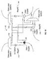
- broadband coupler 120can includes at least a 1 ⁇ 2 coupler 124 , to add traffic, a 1 ⁇ 2 coupler 126 , to drop traffic, a booster 128 that compensates for add/drop loss on ring 112 , a pre-amplifier 130 to compensates for add/drop loss on ring 112 and an in-amplifier 132 to compensate for add/drop loss on the first ring.
- the rings of network 110can have one or more working fibers 134 and protection fibers 136 that carry all of the optical signal traffic.
- Optical signal traffictravels in a clockwise direction in working fiber 134 and in a counter-clockwise direction in protection fiber 136 .
- At least one 1 ⁇ 1 or 1 ⁇ 2 switch 138is coupled to working fiber 134
- at least one 1 ⁇ 1 or 1 ⁇ 2 switch 140is coupled to protection fiber 136 .
- an open 1 ⁇ 1 switchis maintained on the rings of network 110 in order to eliminate a fiber ring lasing phenomenon that can arise in response to gain provided by an in-line amplifier 132 that is coupled to the ring.
- Each 1 ⁇ 1 or 1 ⁇ 2 switch 138 and 140is maintained in an open position if there isn't a break point in the ring of network 110 .
- Each 1 ⁇ 1 or 1 ⁇ 2 switch 138 and 140is closed when there is a break point in the ring.
- an all-optical hub 142couples first ring 112 to one or more second ring 144 .
- All-optical hub 142separates optical signals in each ring 112 and 144 into wavelength bands. The number of wavelength bands is equal to the number of rings 112 and 144 in network 110 .
- All-optical hub 142can include at least one 1 ⁇ N band-splitter 146 and an N ⁇ 1 coupler 148 that couples optical signal traffic among rings 112 and 144 .
- Nis the number of rings 112 and 144 that are coupled which in the FIG. 19 embodiment is three.
- Each 1 ⁇ N band splitter 146launches optical traffic that originates from one ring 112 and 144 to one or more different rings 144 or 112 in response to its associated wavelength band.
- Each N ⁇ 1 148 couplerlaunches to any selected ring 112 or 144 in network 110 the wavelength bands from the other rings 144 or 112 .
- first and a second wavelength-dependent three-port add-drop filters 150 and 152are coupled to each network node 118 .
- First wavelength-dependent three-port add-drop filter 150adds signal traffic in an add direction; and second wavelength-dependent three-port add-drop filter 152 drops traffic in a drop direction.
- Each first and second wavelength-dependent three-port add-drop filter 150 and 152is positioned off ring 112 and 144 .
- first wavelength dependent three-port add-drop filter 150is coupled to first ring 112 in the add/drop direction and includes input and drop ports.
- a plurality of wavelength-dependent three-port add-drop filterscan be provided and are cascaded at each node 118 for the drop direction in order to drop multiple wavelengths, and also cascaded for the add direction to add multiple wavelengths, see FIG. 20( b )– 20 ( d ).
- one or more expansion modules 156can be coupled to each ring 112 and 144 in order to add and drop more than one wavelength.
- Each expansion module 156can include one or more cascaded three-port optical add/drop filters 158 and a plurality of multiplexed transmitters 160 for adding wavelengths. The wavelengths that are added are different from the wavelengths that are dropped.
- Expansion modules 156can each have an array of parallel filters for dropping wavelengths 162 and an array of multiplexed transmitters 164 for adding wavelengths. Again, the wavelengths added are different from wavelengths that are dropped.
- the drop ports of broadband couplers 120can each include a wavelength-dependent tunable filter 120 .
- Each tunable filter 120reflects non-selected wavelengths to a through port for one cascaded three-port optical add/drop filter to an adjacent cascaded three-port optical add/drop filter.
- the subject matter in the following sectionsrelates generally to a method of transporting ultra-dense wavelength division multiplexed (U-DWDM) data in optical communication systems and more particularly, to an optical double-sideband modulation technique that presents ever higher spectral efficiency than optical single-sideband modulation technique.
- U-DWDMultra-dense wavelength division multiplexed
- a sub-carrier multiplexed (“SCM”) optical transmission systemcan be used to transmit both analog or digital signals (W. I. Way, Subcarrier Multiplexed Lightwave Systems for Subscriber Loop Applications, Journal of Lightwave Technology, 1988, pp. 1806–1818).
- SCMsub-carrier multiplexed
- multiple CW DFB lasersor a laser array with external modulators (or multiple externally-modulated lasers) with close channel spacing such as ⁇ 10 GHz are used.
- the problem with this approachis that not only the center wavelength of each laser must be locked precisely, but also the physical size of the U-DWDM array may be large.
- the multiple DFB lasers on FIG. 24( a )are replaced by a optical comb generator (“Laser for generating an optical comb”, U.S. Pat. No. 6,163,553, Dec. 19, 2000; “Optical frequency generator”, U.S. Pat. No. 6,008,931, Dec. 28, 1999) in combination with multiple narrowband optical filters.
- the advantage of this approachis that the narrow channel spacing can be maintained steadily. However, the physical size and the cost of the narrowband optical filters still present a problem.
- ODSBoptical double-sideband
- OSSBoptical single-sideband
- both ODSB and OSDB techniquesuse a narrowband optical filter to extract only one of the information sidebands and can significantly reduce the system penalty due to fiber chromatic dispersions.
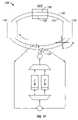
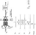
- Both ODSB and OSSBcan use Lithium-Niobate Mach Zehnder interferometer (MZI) modulator to carry out the modulation techniques. Their operation principles are shown in FIGS. 1A , 1 B, and 1 C, respectively.
- MZIMach Zehnder interferometer
- the present inventionproposes a new U-DWDM approach by using ODSB modulation technique to achieve a high spectral efficiency.
- One or two wavelength-locked CW DFB lasersare used as the optical sources for one or two externally modulated LiNbO 3 MZIs, respectively.
- the center wavelength of each DFB lasersmust be offset from a standard ITU wavelength.
- Each MZIis modulated by a few subcarrier multiplexed RE/microwave signals using ODSB modulation. If one uses only one MZI, the modulated output from MZI is passed through a narrowband optical filter. If one uses two MZIs, the two sets of ODSB modulated signals are then combined and passed through a narrowband optical filter.
- the modulating signal center frequenciescan be adjusted, depending on (1) the bandwidth of the MZI, (2) the offset of the laser center frequency from a standard ITU grid, (3) the bandwidth of the narrowband optical filter, and (4) the minimization of system performance penalty due to four-wave mixing and other optical nonlinear effects.
- FIGS. 4( f ) to 24 ( j )show various preferred embodiments.
- FIG. 24( f )for an ITU window centered at ⁇ 0 , we use a wavelength-locked laser centered at ⁇ 1 (equals to ⁇ 0 ⁇ or ⁇ 0 + ⁇ ), where ⁇ is the offset wavelength.
- the output of the laseris connected to the input of an MZI modulator via a polarization-maintaining fiber.
- the MZI modulatoris modulated by multi-channel RF/microwave signals.
- These RF/microwave signalscan b of any modulation type that can be demodulated by a narrowband channel optical filter and envelop detection, for example, amplitude-shifted-keying (ASK) signals.
- ASKamplitude-shifted-keying
- the modulation on the MZIis based on ODSB technique mentioned previously in FIG. 24( c ). Consequently, the outputs of each MZI are double-sideband signals with suppressed carrier as shown in FIG. 24( a ).
- the double-sideband signalsare then sent to a narrowband optical bandpass filter (BPF) or DWDM multiplexer.
- BPFoptical bandpass filter
- the center frequency of the BPF or the DWDM multiplexeris at ⁇ 0 , and its pass-band is just enough to pass one sideband of each modulating signal.
- the BPF or DWDM multiplexercan be designed such that (1) its pass-band is just enough to pass a group of singlesideband signals under all environmental variations (e.g., temperature change, and (2) its edge roll-off can be sharp enough to cut off the unwanted single sidebands on another side of the optical carrier.
- the wanted single-sidebandsshould also stay away from the edge of the BPF or DWDM multiplexer to avoid being affected by the nonlinear phase/group delay occurring at the filter band-edges.
- FIG. 24( g )An alternative approach is shown in FIG. 24( g ).
- the output of each laseris connected to the input of an MZI modulator via a polarization-maintaining fiber.
- the modulation bandwidth of each MZI modulatorcan be half of that used in FIG. 24( f ).
- Each MZI modulatoris also modulated by multi-channel RF/microwave signals, but the number of signals is half of that in FIG. 24( f ).
- the outputs of each MZIare also double-sideband signals with suppressed carrier.
- the first ODSB output from the upper MZI in FIG. 24( f ) & 24 ( g )is centered at ⁇ 1
- the other ODSB output from the lower MZI in FIG. 24( f ) & 24 ( g )is centered at ⁇ 2
- the two ODSB signalsare then combined and sent to an optical or multiplexer.
- the center frequency of the BPF or the DWDM multiplexeris at ⁇ 0
- its pass-bandis just enough to pass one sideband of each modulating signal.
- Shown in FIG. 24( f ) & 24 ( g )are four different modulating signals which can be passed through the BPF or DWDM multiplexer.
- the final resultis an output signal consisting of four different single-sidebands of information. Note that f 1 and f 2 of the subcarrier multiplexed signals should be high enough such that the unwanted single sidebands can be eliminated more completely.
- FIG. 24( h )a ODSB transmitter is being used to generate two offset optical carriers.
- Two narrowband optical filtersare used to filter out the optical carriers at ⁇ 1 and ⁇ 2 , respectively.
- the rest of the operation principleis the same as that in FIG. 24( f ) & 24 ( g ).
- the second such approachis to use a direct frequency-modulated (FM) LD as the two offset-optical-carrier generating source, as shown in FIG. 24( i ).
- FMdirect frequency-modulated
- the third such approachis to use a direct phase-modulated (PM) LD as the two offset-optical-carrier generating source, as shown in FIG. 24( j ).
- PMphase-modulated
Landscapes
- Engineering & Computer Science (AREA)
- Computer Networks & Wireless Communication (AREA)
- Signal Processing (AREA)
- Physics & Mathematics (AREA)
- Electromagnetism (AREA)
- Optics & Photonics (AREA)
- Nonlinear Science (AREA)
- Computing Systems (AREA)
- Ceramic Engineering (AREA)
- General Physics & Mathematics (AREA)
- Crystallography & Structural Chemistry (AREA)
- Chemical & Material Sciences (AREA)
- Optical Communication System (AREA)
- Small-Scale Networks (AREA)
Abstract
Description
Claims (36)
Priority Applications (4)
| Application Number | Priority Date | Filing Date | Title |
|---|---|---|---|
| US10/178,071US7120359B2 (en) | 2000-05-22 | 2002-06-19 | Broadcast and select all optical network |
| AU2003243739AAU2003243739A1 (en) | 2002-06-19 | 2003-06-19 | Brodcast and select all optical network |
| PCT/US2003/019725WO2004002024A1 (en) | 2002-06-19 | 2003-06-19 | Brodcast and select all optical network |
| US11/450,136US7515833B2 (en) | 2000-05-22 | 2006-06-09 | Optical double sideband modulation technique with increased spectral efficiency |
Applications Claiming Priority (6)
| Application Number | Priority Date | Filing Date | Title |
|---|---|---|---|
| US09/575,811US6525857B1 (en) | 2000-03-07 | 2000-05-22 | Method and apparatus for interleaved optical single sideband modulation |
| US22978400P | 2000-09-01 | 2000-09-01 | |
| US30156401P | 2001-06-28 | 2001-06-28 | |
| US30922001P | 2001-07-31 | 2001-07-31 | |
| US09/990,196US6895184B2 (en) | 2000-05-22 | 2001-11-21 | Interconnected broadcast and select optical networks with shared wavelengths |
| US10/178,071US7120359B2 (en) | 2000-05-22 | 2002-06-19 | Broadcast and select all optical network |
Related Parent Applications (2)
| Application Number | Title | Priority Date | Filing Date |
|---|---|---|---|
| US09/575,811Continuation-In-PartUS6525857B1 (en) | 2000-03-07 | 2000-05-22 | Method and apparatus for interleaved optical single sideband modulation |
| US09/990,196Continuation-In-PartUS6895184B2 (en) | 2000-05-22 | 2001-11-21 | Interconnected broadcast and select optical networks with shared wavelengths |
Related Child Applications (1)
| Application Number | Title | Priority Date | Filing Date |
|---|---|---|---|
| US11/450,136ContinuationUS7515833B2 (en) | 2000-05-22 | 2006-06-09 | Optical double sideband modulation technique with increased spectral efficiency |
Publications (2)
| Publication Number | Publication Date |
|---|---|
| US20030025961A1 US20030025961A1 (en) | 2003-02-06 |
| US7120359B2true US7120359B2 (en) | 2006-10-10 |
Family
ID=29999115
Family Applications (2)
| Application Number | Title | Priority Date | Filing Date |
|---|---|---|---|
| US10/178,071Expired - LifetimeUS7120359B2 (en) | 2000-05-22 | 2002-06-19 | Broadcast and select all optical network |
| US11/450,136Expired - Fee RelatedUS7515833B2 (en) | 2000-05-22 | 2006-06-09 | Optical double sideband modulation technique with increased spectral efficiency |
Family Applications After (1)
| Application Number | Title | Priority Date | Filing Date |
|---|---|---|---|
| US11/450,136Expired - Fee RelatedUS7515833B2 (en) | 2000-05-22 | 2006-06-09 | Optical double sideband modulation technique with increased spectral efficiency |
Country Status (3)
| Country | Link |
|---|---|
| US (2) | US7120359B2 (en) |
| AU (1) | AU2003243739A1 (en) |
| WO (1) | WO2004002024A1 (en) |
Cited By (21)
| Publication number | Priority date | Publication date | Assignee | Title |
|---|---|---|---|---|
| US20050010681A1 (en)* | 2003-06-03 | 2005-01-13 | Cisco Technology, Inc. A California Corporation | Computing a path for an open ended uni-directional path protected switched ring |
| US20050180749A1 (en)* | 2003-11-07 | 2005-08-18 | Bikash Koley | System and method for a resilient optical Ethernet networksupporting automatic protection switching |
| US20050196169A1 (en)* | 2004-03-03 | 2005-09-08 | Fujitsu Limited | System and method for communicating traffic between optical rings |
| US20060013587A1 (en)* | 2004-07-15 | 2006-01-19 | Scott Kenneth G | Modular wavelength selective switch |
| US20060110162A1 (en)* | 2004-11-22 | 2006-05-25 | Fujitsu Network Communications, Inc. | Optical ring network for extended broadcasting |
| US20070207809A1 (en)* | 2003-07-14 | 2007-09-06 | Mutabazi Steven L | Networking corridors for packet data and voice communications |
| US20070297801A1 (en)* | 2006-06-02 | 2007-12-27 | Mostert Willem A | DWDM transport of CATV and digital signals over optical fiber in low-dispersion spectral regions |
| US7499647B2 (en) | 2000-05-22 | 2009-03-03 | Opvista Incorporated | Fully protected broadcast and select all optical network |
| US7515833B2 (en) | 2000-05-22 | 2009-04-07 | Opvista Incorporated | Optical double sideband modulation technique with increased spectral efficiency |
| US20090103924A1 (en)* | 2005-08-08 | 2009-04-23 | Tetsuya Kawanishi | Fourth harmonic generating system using optical double side-band suppressed carrier modulator |
| US7577367B2 (en) | 2004-06-15 | 2009-08-18 | Op Vista Incorporated | Optical communication using duobinary modulation |
| US7773883B1 (en) | 2007-05-04 | 2010-08-10 | Vello Systems, Inc. | Single-fiber optical ring networks based on optical double sideband modulation |
| US8139476B2 (en) | 2005-10-13 | 2012-03-20 | Vello Systems, Inc. | Optical ring networks using circulating optical probe in protection switching with automatic reversion |
| US8160453B1 (en)* | 2006-03-30 | 2012-04-17 | Rockstar Bidco, LP | Protection switching with transmitter compensation function |
| US8175458B2 (en) | 2007-07-17 | 2012-05-08 | Vello Systems, Inc. | Optical ring networks having node-to-node optical communication channels for carrying data traffic |
| US20130094857A1 (en)* | 2011-10-12 | 2013-04-18 | Adva Ag Optical Networking | Remote node and network architecture and data transmission method for a fiber-optic network, especially for low bit-rate data transmission |
| US8542999B2 (en) | 2011-02-01 | 2013-09-24 | Vello Systems, Inc. | Minimizing bandwidth narrowing penalties in a wavelength selective switch optical network |
| US8705741B2 (en) | 2010-02-22 | 2014-04-22 | Vello Systems, Inc. | Subchannel security at the optical layer |
| US8744262B2 (en) | 2009-12-08 | 2014-06-03 | Vello Systems, Inc. | Optical subchannel routing, protection switching and security |
| US20140369683A1 (en)* | 2009-10-16 | 2014-12-18 | Xieon Networks S.A.R.L. | Optical network and method for processing data in an optical network |
| US20200106543A1 (en)* | 2018-10-01 | 2020-04-02 | Huawei Technologies Co., Ltd. | Systems and method of multi-laser wavelength control |
Families Citing this family (45)
| Publication number | Priority date | Publication date | Assignee | Title |
|---|---|---|---|---|
| DE60113877T2 (en)* | 2001-01-31 | 2006-06-14 | Ericsson Telefon Ab L M | METHOD AND ARRANGEMENT FOR TRANSMISSION IN AN OPTICAL NETWORK |
| US7231148B2 (en)* | 2002-03-28 | 2007-06-12 | Fujitsu Limited | Flexible open ring optical network and method |
| US20040052530A1 (en)* | 2002-09-17 | 2004-03-18 | Cechan Tian | Optical network with distributed sub-band rejections |
| WO2004028999A2 (en)* | 2002-09-23 | 2004-04-08 | Basf Aktiengesellschaft | Thin films of oxidic materials having a high dielectric constant |
| US7483636B2 (en)* | 2003-07-28 | 2009-01-27 | Fujitsu Limited | Optical network with sub-band rejection and bypass |
| US20050095001A1 (en)* | 2003-10-29 | 2005-05-05 | Fujitsu Limited | Method and system for increasing network capacity in an optical network |
| EP1882319A2 (en)* | 2005-05-02 | 2008-01-30 | Opvista, Incorporated | Multiple interconnected broadcast and select optical ring networks with revertible protection switch |
| WO2009012419A2 (en)* | 2007-07-17 | 2009-01-22 | Opvista Incorporated | Optical wavelength-division-multiplexed (wdm) comb generator using a single laser |
| US20090290878A1 (en)* | 2008-05-22 | 2009-11-26 | Nec Laboratories America, Inc. | Generating an Optical OFDM Signal with Reduced OSNR Requirement |
| CN102113256B (en)* | 2008-07-31 | 2015-06-17 | 骁阳网络有限公司 | Method for processing data in an optical network, optical network component and communication system |
| US8934773B2 (en)* | 2008-07-31 | 2015-01-13 | Xieon Networks S.A.R.L. | Method for data processing in an optical network, optical network component and communication system |
| US8554074B2 (en) | 2009-05-06 | 2013-10-08 | Ciena Corporation | Colorless, directionless, and gridless optical network, node, and method |
| US8509618B2 (en) | 2009-05-06 | 2013-08-13 | Ciena Corporation | Photonic routing systems and methods for loop avoidance |
| EP2346191B1 (en)* | 2010-01-13 | 2014-12-17 | Xieon Networks S.à.r.l. | Optical Modulator |
| US8831439B2 (en) | 2010-10-05 | 2014-09-09 | Infinera Corporation | Upsampling optical transmitter |
| US9106343B2 (en)* | 2011-07-29 | 2015-08-11 | Zte (Usa) Inc. | Method and apparatus for performing temporal polarization interleaving in an optical transmitting system |
| JP6048410B2 (en)* | 2011-09-30 | 2016-12-21 | 住友大阪セメント株式会社 | Carrier suppression light generator |
| US9083484B2 (en) | 2012-02-13 | 2015-07-14 | Ciena Corporation | Software defined networking photonic routing systems and methods |
| EP2888872A4 (en)* | 2012-08-23 | 2016-03-30 | Finisar Corp | Integrated laser and modulator transmitter for catv applications |
| US9673908B2 (en)* | 2013-06-19 | 2017-06-06 | The University Of Sydney | Device and a method for generating an electrical signal with a suppressed frequency band |
| US9240842B2 (en)* | 2014-03-24 | 2016-01-19 | The United States Of America As Represented By The Secretary Of The Air Force | Isolation of RF signals using optical single side band modulation combined with optical filtering |
| US9807543B2 (en) | 2014-04-17 | 2017-10-31 | Z-Integrated Digital Technologies, Inc. | Electronic test device data communication |
| US9451343B2 (en) | 2015-01-30 | 2016-09-20 | Ciena Corporation | Control plane extensions for optical broadcast networks |
| DE102015221283B4 (en)* | 2015-10-30 | 2017-09-14 | Deutsches Zentrum für Luft- und Raumfahrt e.V. | Transmitter for a free beam optical communication system and associated receiver terminal |
| US11251878B2 (en) | 2018-02-07 | 2022-02-15 | Infinera Corporation | Independently routable digital subcarriers for optical communication networks |
| US11368228B2 (en) | 2018-04-13 | 2022-06-21 | Infinera Corporation | Apparatuses and methods for digital subcarrier parameter modifications for optical communication networks |
| JP7099088B2 (en)* | 2018-06-29 | 2022-07-12 | 日本電信電話株式会社 | Dispersion compensation system and dispersion compensation method |
| US11095389B2 (en) | 2018-07-12 | 2021-08-17 | Infiriera Corporation | Subcarrier based data center network architecture |
| US11075694B2 (en) | 2019-03-04 | 2021-07-27 | Infinera Corporation | Frequency division multiple access optical subcarriers |
| US11258528B2 (en) | 2019-09-22 | 2022-02-22 | Infinera Corporation | Frequency division multiple access optical subcarriers |
| US11336369B2 (en) | 2019-03-22 | 2022-05-17 | Infinera Corporation | Framework for handling signal integrity using ASE in optical networks |
| US11418312B2 (en) | 2019-04-19 | 2022-08-16 | Infinera Corporation | Synchronization for subcarrier communication |
| US10972184B2 (en) | 2019-05-07 | 2021-04-06 | Infinera Corporation | Bidirectional optical communications |
| US11296812B2 (en) | 2019-05-14 | 2022-04-05 | Infinera Corporation | Out-of-band communication channel for subcarrier-based optical communication systems |
| US11239935B2 (en) | 2019-05-14 | 2022-02-01 | Infinera Corporation | Out-of-band communication channel for subcarrier-based optical communication systems |
| US11190291B2 (en) | 2019-05-14 | 2021-11-30 | Infinera Corporation | Out-of-band communication channel for subcarrier-based optical communication systems |
| US11476966B2 (en) | 2019-05-14 | 2022-10-18 | Infinera Corporation | Out-of-band communication channel for subcarrier-based optical communication systems |
| US11489613B2 (en) | 2019-05-14 | 2022-11-01 | Infinera Corporation | Out-of-band communication channel for subcarrier-based optical communication systems |
| US10965378B2 (en) | 2019-05-14 | 2021-03-30 | Infinera Corporation | Out-of-band communication channel for sub-carrier-based optical communication systems |
| US11297005B2 (en) | 2019-09-05 | 2022-04-05 | Infiriera Corporation | Dynamically switching queueing schemes for network switches |
| WO2021072290A1 (en)* | 2019-10-10 | 2021-04-15 | Steven Joseph Hand | Optical subcarrier dual-path protection and restoration for optical communications networks |
| EP4042607A1 (en) | 2019-10-10 | 2022-08-17 | Infinera Corporation | Network switches systems for optical communications networks |
| AU2020364088B2 (en) | 2019-10-10 | 2025-04-17 | Infinera Corporation | Optical subcarrier dual-path protection and restoration for optical communications networks |
| US11356180B2 (en) | 2019-10-10 | 2022-06-07 | Infinera Corporation | Hub-leaf laser synchronization |
| JP7543733B2 (en)* | 2020-07-06 | 2024-09-03 | 富士通株式会社 | Optical transmission device and optical transmission method |
Citations (22)
| Publication number | Priority date | Publication date | Assignee | Title |
|---|---|---|---|---|
| US5301058A (en) | 1990-12-31 | 1994-04-05 | Gte Laboratories Incorporated | Single sideband optical modulator for lightwave systems |
| US5333000A (en) | 1992-04-03 | 1994-07-26 | The United States Of America As Represented By The United States Department Of Energy | Coherent optical monolithic phased-array antenna steering system |
| US5442623A (en)* | 1992-08-17 | 1995-08-15 | Bell Communications Research, Inc. | Passive protected self healing ring network |
| US5596436A (en) | 1995-07-14 | 1997-01-21 | The Regents Of The University Of California | Subcarrier multiplexing with dispersion reduction and direct detection |
| US5717795A (en)* | 1994-02-17 | 1998-02-10 | Kabushiki Kaisha Toshiba | Optical wavelength division multiplexed network system |
| US5742416A (en)* | 1996-03-28 | 1998-04-21 | Ciena Corp. | Bidirectional WDM optical communication systems with bidirectional optical amplifiers |
| US5745273A (en) | 1996-11-27 | 1998-04-28 | Lucent Technologies Inc. | Device for single sideband modulation of an optical signal |
| US5949560A (en) | 1997-02-05 | 1999-09-07 | Northern Telecom Limited | Optical transmission system |
| US5982963A (en) | 1997-12-15 | 1999-11-09 | University Of Southern California | Tunable nonlinearly chirped grating |
| US6008931A (en) | 1995-04-19 | 1999-12-28 | Heinrich Hertz Institut Fuer Nachrichtentechnik Berlin Gmbh | Optical frequency generator |
| US6023359A (en)* | 1996-10-04 | 2000-02-08 | Nec Corporation | Optical wavelength-division multiplex transmission equipment with a ring structure |
| US6084694A (en) | 1997-08-27 | 2000-07-04 | Nortel Networks Corporation | WDM optical network with passive pass-through at each node |
| US6088141A (en) | 1995-06-26 | 2000-07-11 | Telefonaktiebolaget Lm Ericsson | Self-healing network |
| US6118566A (en) | 1998-11-04 | 2000-09-12 | Corvis Corporation | Optical upconverter apparatuses, methods, and systems |
| US6130766A (en) | 1999-01-07 | 2000-10-10 | Qtera Corporation | Polarization mode dispersion compensation via an automatic tracking of a principal state of polarization |
| US6163553A (en) | 1997-07-18 | 2000-12-19 | Alcatel | Laser for generating an optical comb |
| US6192173B1 (en) | 1999-06-02 | 2001-02-20 | Nortel Networks Limited | Flexible WDM network architecture |
| US6195186B1 (en)* | 1996-12-04 | 2001-02-27 | Nec Corporation | Optical WDM ring network |
| US20020015553A1 (en) | 2000-05-18 | 2002-02-07 | Claringburn Harry R. | Radiation power equalizer |
| US6351323B1 (en) | 1998-04-02 | 2002-02-26 | Fujitsu Limited | Optical transmission apparatus, optical transmission system, and optical terminal station |
| US20030169470A1 (en)* | 2000-11-07 | 2003-09-11 | Oni Systems Corp. | Method and system for bi-directional path switched network |
| US6657952B1 (en)* | 1997-11-28 | 2003-12-02 | Nec Corporation | Ring network for sharing protection resource by working communication paths |
Family Cites Families (87)
| Publication number | Priority date | Publication date | Assignee | Title |
|---|---|---|---|---|
| US5062684A (en) | 1990-01-17 | 1991-11-05 | At&T Bell Laboratories | Optical fiber filter |
| US5539559A (en)* | 1990-12-18 | 1996-07-23 | Bell Communications Research Inc. | Apparatus and method for photonic contention resolution in a large ATM switch |
| US5239401A (en)* | 1990-12-31 | 1993-08-24 | Gte Laboratories Incorporated | Optical modulator for cancellation of second-order intermodulation products in lightwave systems |
| US5101450A (en)* | 1991-01-23 | 1992-03-31 | Gte Laboratories Incorporated | Quadrature optical phase modulators for lightwave systems |
| US5390188A (en)* | 1993-08-02 | 1995-02-14 | Synoptics | Method and apparatus for measuring and monitoring the performance within a ring communication network |
| JP3396270B2 (en) | 1993-08-10 | 2003-04-14 | 富士通株式会社 | Optical dispersion compensation method |
| IT1265018B1 (en) | 1993-08-10 | 1996-10-17 | Cselt Centro Studi Lab Telecom | DEVICE FOR EXTRACTION AND REINSERTION OF AN OPTICAL CARRIER IN OPTICAL COMMUNICATION NETWORKS. |
| US5509093A (en)* | 1993-10-13 | 1996-04-16 | Micron Optics, Inc. | Temperature compensated fiber fabry-perot filters |
| GB9401488D0 (en)* | 1994-01-26 | 1994-03-23 | British Telecomm | Optical communications |
| US5764821A (en)* | 1994-02-06 | 1998-06-09 | Lucent Technologies Inc. | Large capacity local access network |
| JP3434869B2 (en) | 1994-02-07 | 2003-08-11 | 株式会社日立製作所 | Optical regenerative repeater and optical transmission device |
| CA2139957C (en)* | 1994-02-18 | 1999-02-09 | Andrew R. Chraplyvy | Multi-channel optical fiber communication system |
| IT1272846B (en)* | 1994-11-25 | 1997-06-30 | Pirelli Cavi Spa | "WAVELENGTH MULTIPLATION TELECOMMUNICATION SYSTEM AND METHOD, WITH CONTROLLED SEPARATION OF THE OUTPUT CHANNELS AND FOR THE DETERMINATION OF THE SIGNAL / OPTICAL NOISE RATIO" |
| EP0717482A1 (en)* | 1994-12-14 | 1996-06-19 | AT&T Corp. | Semiconductor interferometric optical wavelength conversion device |
| JP3376144B2 (en)* | 1994-12-28 | 2003-02-10 | 日本電気株式会社 | Optical network device and optical transmission system |
| US5680235A (en)* | 1995-04-13 | 1997-10-21 | Telefonaktiebolaget Lm Ericsson | Optical multichannel system |
| US5784184A (en)* | 1995-05-11 | 1998-07-21 | Ciena Corporation | WDM Optical communication systems with remodulators and remodulating channel selectors |
| FR2736777B1 (en)* | 1995-07-12 | 1997-08-08 | Alcatel Nv | OPTICAL TRANSMISSION NETWORK WITH WAVELENGTH MULTIPLEXING |
| GB9516017D0 (en)* | 1995-08-04 | 1995-10-04 | Stc Submarine Systems Ltd | Optical level control in wavelength add-drop multiplexing branching units |
| DE19529376A1 (en)* | 1995-08-10 | 1997-02-13 | Sel Alcatel Ag | Optical TDMA ring network with a central transmitting and receiving device |
| US5625478A (en)* | 1995-09-14 | 1997-04-29 | Lucent Technologies Inc. | Optically restorable WDM ring network using simple add/drop circuitry |
| JP3356365B2 (en)* | 1995-09-19 | 2002-12-16 | ケイディーディーアイ株式会社 | Optical ADM device |
| US5617233A (en)* | 1995-09-28 | 1997-04-01 | The United States Of America As Represented By The Secretary Of The Air Force | Transparent optical node structure |
| US5608825A (en)* | 1996-02-01 | 1997-03-04 | Jds Fitel Inc. | Multi-wavelength filtering device using optical fiber Bragg grating |
| KR100342431B1 (en)* | 2000-09-07 | 2002-07-03 | 윤덕용 | A multi-wavelength locking method and locker for WDM system |
| US5710650A (en)* | 1996-03-14 | 1998-01-20 | Alcatel Network Systems, Inc. | Dispersion-reducing multiple wavelength division multiplexing optical fiber transceiver and methods for using and assembling same |
| US5982518A (en) | 1996-03-27 | 1999-11-09 | Ciena Corporation | Optical add-drop multiplexers compatible with very dense WDM optical communication systems |
| JPH09270770A (en)* | 1996-04-02 | 1997-10-14 | Kokusai Denshin Denwa Co Ltd <Kdd> | Optical add / drop device |
| DE19628131C2 (en)* | 1996-07-12 | 2003-07-17 | Semikron Elektronik Gmbh | Gate voltage limitation for a circuit arrangement |
| US5781327A (en)* | 1996-08-19 | 1998-07-14 | Trw Inc. | Optically efficient high dynamic range electro-optic modulator |
| US6208443B1 (en)* | 1996-10-03 | 2001-03-27 | International Business Machines Corporation | Dynamic optical add-drop multiplexers and wavelength-routing networks with improved survivability and minimized spectral filtering |
| CA2188358A1 (en)* | 1996-10-21 | 1998-04-21 | Michael J. Sieben | optical modulation system |
| US6201909B1 (en)* | 1996-10-25 | 2001-03-13 | Arroyo Optics, Inc. | Wavelength selective optical routers |
| US5734493A (en)* | 1996-11-01 | 1998-03-31 | Lucent Technologies Inc. | Optical frequency conversion device |
| US5778118A (en)* | 1996-12-03 | 1998-07-07 | Ciena Corporation | Optical add-drop multiplexers for WDM optical communication systems |
| JP3618943B2 (en)* | 1996-12-17 | 2005-02-09 | キヤノン株式会社 | Ink jet recording head and ink jet recording apparatus |
| US5917638A (en)* | 1997-02-13 | 1999-06-29 | Lucent Technologies, Inc. | Duo-binary signal encoding |
| US5938309A (en)* | 1997-03-18 | 1999-08-17 | Ciena Corporation | Bit-rate transparent WDM optical communication system with remodulators |
| US6035080A (en)* | 1997-06-20 | 2000-03-07 | Henry; Charles Howard | Reconfigurable add-drop multiplexer for optical communications systems |
| US6191854B1 (en)* | 1997-06-23 | 2001-02-20 | Pirelli Cavi E Sistemi S.P.A. | Optical telecommunications system |
| DE19731494C2 (en)* | 1997-07-22 | 1999-05-27 | Siemens Ag | Method and arrangement for data transmission using wavelength division multiplexing in an optical ring network |
| US6222654B1 (en)* | 1997-08-04 | 2001-04-24 | Lucent Technologies, Inc. | Optical node system for a ring architecture and method thereof |
| JP3930952B2 (en)* | 1997-10-20 | 2007-06-13 | 富士通株式会社 | Optical cross-connect device, optical add / drop device, and light source device |
| US5870212A (en)* | 1998-01-14 | 1999-02-09 | Mciworldcom, Inc. | Self-healing optical network |
| US6195351B1 (en)* | 1998-01-28 | 2001-02-27 | 3Com Corporation | Logical switch set |
| JP3909946B2 (en)* | 1998-01-30 | 2007-04-25 | 富士通株式会社 | Bidirectional wavelength switch and optical multiplexer / demultiplexer |
| US6259836B1 (en)* | 1998-05-14 | 2001-07-10 | Telecommunications Research Laboratories | Optical frequency shifter and transmission system |
| SE520876C2 (en)* | 1998-06-10 | 2003-09-09 | Ericsson Telefon Ab L M | ADD / Drpo node for an optical WDM network that has traffic only between neighboring nodes |
| SE520943C2 (en)* | 1998-06-10 | 2003-09-16 | Ericsson Telefon Ab L M | Add / drop node arranged to be connected in a wdm-type fiber optic network |
| DE19828614A1 (en) | 1998-06-26 | 1999-12-30 | Ams Optotech Vertrieb Gmbh | Transmission method for optical data using optical waveguide |
| US6580537B1 (en)* | 1998-07-17 | 2003-06-17 | Regents Of The University Of California, The | High-throughput, low-latency next generation internet networks using optical label switching and high-speed optical header generation, detection and reinsertion |
| US20020063928A1 (en)* | 1998-08-31 | 2002-05-30 | Per Bang Hansen | Filtering of data-encoded optical signals |
| JP4207260B2 (en)* | 1998-09-03 | 2009-01-14 | ソニー株式会社 | Image recording device |
| US6292598B1 (en)* | 1998-11-04 | 2001-09-18 | Corvis Corporation | Optical transmission apparatuses, methods, and systems |
| US6404535B1 (en)* | 1998-11-30 | 2002-06-11 | Trw Inc. | Optically implemented wideband complex correlator using a multi-mode imaging device |
| US6219161B1 (en)* | 1999-01-25 | 2001-04-17 | Telcordia Technologies, Inc. | Optical layer survivability and security system |
| US6466342B1 (en) | 1999-02-18 | 2002-10-15 | At&T Corp. | Optical transmission system and method using an optical carrier drop/add transceiver |
| FI108488B (en)* | 1999-03-12 | 2002-01-31 | Nokia Corp | Dispersion compensation in an optical communication network and an optical communication network |
| US6433904B1 (en)* | 1999-07-27 | 2002-08-13 | Sycamore Networks, Inc. | Method and apparatus for improving transmission performance over wavelength division multiplexed optical communication links using forward error correction coding |
| US6369923B1 (en)* | 1999-09-07 | 2002-04-09 | Cinta Corporation | Multiwavelength stabilization with a single reference comb filter in DWDM systems |
| US6385204B1 (en)* | 1999-11-22 | 2002-05-07 | Worldcom, Inc. | Network architecture and call processing system |
| US6661976B1 (en)* | 2000-01-05 | 2003-12-09 | At&T Corp. | Method and system for single-sideband optical signal generation and transmission |
| EP1132844A3 (en)* | 2000-03-02 | 2002-06-05 | Telseon IP Services Inc. | E-commerce system facilitating service networks including broadband communication service networks |
| AU2001252889A1 (en)* | 2000-03-07 | 2001-09-17 | Corning Inc. | A protection switch in a single two-fiber optical channel shared protection ring |
| US6525857B1 (en) | 2000-03-07 | 2003-02-25 | Opvista, Inc. | Method and apparatus for interleaved optical single sideband modulation |
| US20020114034A1 (en)* | 2000-05-22 | 2002-08-22 | Winston Way | Split wave method and apparatus for transmitting data in long-haul optical fiber systems |
| US7120359B2 (en)* | 2000-05-22 | 2006-10-10 | Opvista Incorporated | Broadcast and select all optical network |
| US7499647B2 (en)* | 2000-05-22 | 2009-03-03 | Opvista Incorporated | Fully protected broadcast and select all optical network |
| US6895184B2 (en)* | 2000-05-22 | 2005-05-17 | Opvista, Inc. | Interconnected broadcast and select optical networks with shared wavelengths |
| US6560252B1 (en)* | 2000-07-20 | 2003-05-06 | Jds Uniphase Inc. | Method and device for wavelength locking |
| US7024112B2 (en) | 2000-09-11 | 2006-04-04 | Opvista Incorporated | In-band wavelength conversion wavelength buffering and multi-protocol lambda switching |
| US6788899B2 (en)* | 2000-09-11 | 2004-09-07 | Winston I. Way | Dynamic wavelength add/drop multiplexer for UDWDM optical communication system |
| US6829215B2 (en)* | 2000-10-31 | 2004-12-07 | Marconi Intellectual Property (Ringfence) Inc. | IP multi-homing |
| US6339663B1 (en)* | 2000-12-22 | 2002-01-15 | Seneca Networks, Inc. | Bidirectional WDM optical communication system with bidirectional optical service channels |
| AU2002251975A1 (en) | 2001-01-09 | 2002-07-30 | Opvista, Inc. | Split wave method and apparatus for transmitting data in long-haul optical fiber systems |
| JP4646048B2 (en) | 2001-03-02 | 2011-03-09 | 日本電気株式会社 | Single sideband signal light generation method and single sideband signal light generation circuit |
| JP2002271354A (en)* | 2001-03-06 | 2002-09-20 | Fujitsu Ltd | Optical path switching device and optical wavelength division multiplexing diversity communication system using the same |
| US6556744B1 (en)* | 2001-10-12 | 2003-04-29 | Nortel Networks Limited | Reduction of dispersion effects in optical transmission fibre systems |
| US7116905B2 (en) | 2002-03-27 | 2006-10-03 | Fujitsu Limited | Method and system for control signaling in an open ring optical network |
| US20050158047A1 (en)* | 2003-07-16 | 2005-07-21 | Way Winston I. | Optical ring networks with failure protection mechanisms |
| US7483636B2 (en)* | 2003-07-28 | 2009-01-27 | Fujitsu Limited | Optical network with sub-band rejection and bypass |
| KR100557142B1 (en)* | 2003-10-14 | 2006-03-03 | 삼성전자주식회사 | RGB-AMI Optical Transmitter Module |
| US7643761B2 (en)* | 2004-02-19 | 2010-01-05 | Alcatel-Lucent Usa Inc. | Method and apparatus for processing optical duobinary signals |
| US20050201762A1 (en)* | 2004-03-12 | 2005-09-15 | Moeller Lothar Benedict E.J. | Optical RZ-duobinary transmission system with narrow bandwidth optical filter |
| WO2006002080A2 (en) | 2004-06-15 | 2006-01-05 | Opvista Incorporated | Optical communication using duobinary modulation |
| EP1882319A2 (en) | 2005-05-02 | 2008-01-30 | Opvista, Incorporated | Multiple interconnected broadcast and select optical ring networks with revertible protection switch |
| US8139476B2 (en)* | 2005-10-13 | 2012-03-20 | Vello Systems, Inc. | Optical ring networks using circulating optical probe in protection switching with automatic reversion |
- 2002
- 2002-06-19USUS10/178,071patent/US7120359B2/ennot_activeExpired - Lifetime
- 2003
- 2003-06-19AUAU2003243739Apatent/AU2003243739A1/ennot_activeAbandoned
- 2003-06-19WOPCT/US2003/019725patent/WO2004002024A1/ennot_activeApplication Discontinuation
- 2006
- 2006-06-09USUS11/450,136patent/US7515833B2/ennot_activeExpired - Fee Related
Patent Citations (22)
| Publication number | Priority date | Publication date | Assignee | Title |
|---|---|---|---|---|
| US5301058A (en) | 1990-12-31 | 1994-04-05 | Gte Laboratories Incorporated | Single sideband optical modulator for lightwave systems |
| US5333000A (en) | 1992-04-03 | 1994-07-26 | The United States Of America As Represented By The United States Department Of Energy | Coherent optical monolithic phased-array antenna steering system |
| US5442623A (en)* | 1992-08-17 | 1995-08-15 | Bell Communications Research, Inc. | Passive protected self healing ring network |
| US5717795A (en)* | 1994-02-17 | 1998-02-10 | Kabushiki Kaisha Toshiba | Optical wavelength division multiplexed network system |
| US6008931A (en) | 1995-04-19 | 1999-12-28 | Heinrich Hertz Institut Fuer Nachrichtentechnik Berlin Gmbh | Optical frequency generator |
| US6088141A (en) | 1995-06-26 | 2000-07-11 | Telefonaktiebolaget Lm Ericsson | Self-healing network |
| US5596436A (en) | 1995-07-14 | 1997-01-21 | The Regents Of The University Of California | Subcarrier multiplexing with dispersion reduction and direct detection |
| US5742416A (en)* | 1996-03-28 | 1998-04-21 | Ciena Corp. | Bidirectional WDM optical communication systems with bidirectional optical amplifiers |
| US6023359A (en)* | 1996-10-04 | 2000-02-08 | Nec Corporation | Optical wavelength-division multiplex transmission equipment with a ring structure |
| US5745273A (en) | 1996-11-27 | 1998-04-28 | Lucent Technologies Inc. | Device for single sideband modulation of an optical signal |
| US6195186B1 (en)* | 1996-12-04 | 2001-02-27 | Nec Corporation | Optical WDM ring network |
| US5949560A (en) | 1997-02-05 | 1999-09-07 | Northern Telecom Limited | Optical transmission system |
| US6163553A (en) | 1997-07-18 | 2000-12-19 | Alcatel | Laser for generating an optical comb |
| US6084694A (en) | 1997-08-27 | 2000-07-04 | Nortel Networks Corporation | WDM optical network with passive pass-through at each node |
| US6657952B1 (en)* | 1997-11-28 | 2003-12-02 | Nec Corporation | Ring network for sharing protection resource by working communication paths |
| US5982963A (en) | 1997-12-15 | 1999-11-09 | University Of Southern California | Tunable nonlinearly chirped grating |
| US6351323B1 (en) | 1998-04-02 | 2002-02-26 | Fujitsu Limited | Optical transmission apparatus, optical transmission system, and optical terminal station |
| US6118566A (en) | 1998-11-04 | 2000-09-12 | Corvis Corporation | Optical upconverter apparatuses, methods, and systems |
| US6130766A (en) | 1999-01-07 | 2000-10-10 | Qtera Corporation | Polarization mode dispersion compensation via an automatic tracking of a principal state of polarization |
| US6192173B1 (en) | 1999-06-02 | 2001-02-20 | Nortel Networks Limited | Flexible WDM network architecture |
| US20020015553A1 (en) | 2000-05-18 | 2002-02-07 | Claringburn Harry R. | Radiation power equalizer |
| US20030169470A1 (en)* | 2000-11-07 | 2003-09-11 | Oni Systems Corp. | Method and system for bi-directional path switched network |
Non-Patent Citations (12)
Cited By (34)
| Publication number | Priority date | Publication date | Assignee | Title |
|---|---|---|---|---|
| US7515833B2 (en) | 2000-05-22 | 2009-04-07 | Opvista Incorporated | Optical double sideband modulation technique with increased spectral efficiency |
| US7499647B2 (en) | 2000-05-22 | 2009-03-03 | Opvista Incorporated | Fully protected broadcast and select all optical network |
| US8078756B2 (en)* | 2003-06-03 | 2011-12-13 | Cisco Technology, Inc. | Computing a path for an open ended uni-directional path protected switched ring |
| US20050010681A1 (en)* | 2003-06-03 | 2005-01-13 | Cisco Technology, Inc. A California Corporation | Computing a path for an open ended uni-directional path protected switched ring |
| US20070207809A1 (en)* | 2003-07-14 | 2007-09-06 | Mutabazi Steven L | Networking corridors for packet data and voice communications |
| US20050180749A1 (en)* | 2003-11-07 | 2005-08-18 | Bikash Koley | System and method for a resilient optical Ethernet networksupporting automatic protection switching |
| US20050196169A1 (en)* | 2004-03-03 | 2005-09-08 | Fujitsu Limited | System and method for communicating traffic between optical rings |
| US7577367B2 (en) | 2004-06-15 | 2009-08-18 | Op Vista Incorporated | Optical communication using duobinary modulation |
| US20060013587A1 (en)* | 2004-07-15 | 2006-01-19 | Scott Kenneth G | Modular wavelength selective switch |
| US20060110162A1 (en)* | 2004-11-22 | 2006-05-25 | Fujitsu Network Communications, Inc. | Optical ring network for extended broadcasting |
| US7826743B2 (en)* | 2004-11-22 | 2010-11-02 | Fujitsu Limited | Optical ring network for extended broadcasting |
| US20090103924A1 (en)* | 2005-08-08 | 2009-04-23 | Tetsuya Kawanishi | Fourth harmonic generating system using optical double side-band suppressed carrier modulator |
| US7853153B2 (en)* | 2005-08-08 | 2010-12-14 | National Institute Of Information And Communications Technology | Fourth harmonic generating system using optical double side-band suppressed carrier modulator |
| US8139476B2 (en) | 2005-10-13 | 2012-03-20 | Vello Systems, Inc. | Optical ring networks using circulating optical probe in protection switching with automatic reversion |
| US8160453B1 (en)* | 2006-03-30 | 2012-04-17 | Rockstar Bidco, LP | Protection switching with transmitter compensation function |
| US8879904B1 (en) | 2006-03-30 | 2014-11-04 | Rockstar Consortium Us Lp | Protection switching with transmitter compensation function |
| US8682179B1 (en) | 2006-03-30 | 2014-03-25 | Rockstar Consortium Us Lp | Protection switching with transmitter compensation function |
| US20070297801A1 (en)* | 2006-06-02 | 2007-12-27 | Mostert Willem A | DWDM transport of CATV and digital signals over optical fiber in low-dispersion spectral regions |
| US8213797B2 (en)* | 2006-06-02 | 2012-07-03 | Aurora Networks, Inc. | DWDM transport of CATV and digital signals over optical fiber in low-dispersion spectral regions |
| US7773883B1 (en) | 2007-05-04 | 2010-08-10 | Vello Systems, Inc. | Single-fiber optical ring networks based on optical double sideband modulation |
| US8175458B2 (en) | 2007-07-17 | 2012-05-08 | Vello Systems, Inc. | Optical ring networks having node-to-node optical communication channels for carrying data traffic |
| US10038946B2 (en)* | 2009-10-16 | 2018-07-31 | Xieon Networks S.A.R.L. | Optical network and method for processing data in an optical network |
| US20140369683A1 (en)* | 2009-10-16 | 2014-12-18 | Xieon Networks S.A.R.L. | Optical network and method for processing data in an optical network |
| US9054832B2 (en) | 2009-12-08 | 2015-06-09 | Treq Labs, Inc. | Management, monitoring and performance optimization of optical networks |
| US8744262B2 (en) | 2009-12-08 | 2014-06-03 | Vello Systems, Inc. | Optical subchannel routing, protection switching and security |
| US9485050B2 (en) | 2009-12-08 | 2016-11-01 | Treq Labs, Inc. | Subchannel photonic routing, switching and protection with simplified upgrades of WDM optical networks |
| US10630418B2 (en) | 2009-12-08 | 2020-04-21 | Snell Holdings, Llc | Optical subchannel routing, protection switching and security |
| US10972209B2 (en) | 2009-12-08 | 2021-04-06 | Snell Holdings, Llc | Subchannel photonic routing, switching and protection with simplified upgrades of WDM optical networks |
| US8705741B2 (en) | 2010-02-22 | 2014-04-22 | Vello Systems, Inc. | Subchannel security at the optical layer |
| US8542999B2 (en) | 2011-02-01 | 2013-09-24 | Vello Systems, Inc. | Minimizing bandwidth narrowing penalties in a wavelength selective switch optical network |
| US8774628B2 (en)* | 2011-10-12 | 2014-07-08 | Adva Optical Networking Se | Remote node and network architecture and data transmission method for a fiber-optic network, especially for low bit-rate data transmission |
| US20130094857A1 (en)* | 2011-10-12 | 2013-04-18 | Adva Ag Optical Networking | Remote node and network architecture and data transmission method for a fiber-optic network, especially for low bit-rate data transmission |
| US20200106543A1 (en)* | 2018-10-01 | 2020-04-02 | Huawei Technologies Co., Ltd. | Systems and method of multi-laser wavelength control |
| US10979167B2 (en)* | 2018-10-01 | 2021-04-13 | Huawei Technologies Co., Ltd. | Systems and method of multi-laser wavelength control |
Also Published As
| Publication number | Publication date |
|---|---|
| US20060269295A1 (en) | 2006-11-30 |
| US7515833B2 (en) | 2009-04-07 |
| US20030025961A1 (en) | 2003-02-06 |
| AU2003243739A1 (en) | 2004-01-06 |
| WO2004002024A1 (en) | 2003-12-31 |
Similar Documents
| Publication | Publication Date | Title |
|---|---|---|
| US7120359B2 (en) | Broadcast and select all optical network | |
| US6895184B2 (en) | Interconnected broadcast and select optical networks with shared wavelengths | |
| US6614956B2 (en) | Bidirectional WDM optical communication system with bidirectional optical service channels | |
| US5726784A (en) | WDM optical communication system with remodulators and diverse optical transmitters | |
| US6438286B1 (en) | Protection switching in bidirectional WDM optical communication networks with transponders | |
| US7317877B2 (en) | Optical communications systems, devices, and methods | |
| JP4495388B2 (en) | Signal transmission method in wavelength division multiplexing transmission system, wavelength division multiplexing transmitter used in wavelength division multiplexing transmission system, optical add / drop apparatus and transmission apparatus | |
| US5596436A (en) | Subcarrier multiplexing with dispersion reduction and direct detection | |
| US5938309A (en) | Bit-rate transparent WDM optical communication system with remodulators | |
| US8306422B2 (en) | WDM PON protection scheme using a dual port arrayed waveguide grating (AWG) | |
| US7209664B1 (en) | Frequency agile transmitter and receiver architecture for DWDM systems | |
| EP2157722B1 (en) | WDM PON RF overlay architecture based on quantum dot multi-wavelength laser source | |
| Alferness et al. | The evolution of optical systems: Optics everywhere | |
| EP1039670A2 (en) | Wavelength division multiplexed system for optical access rings | |
| US6661973B1 (en) | Optical transmission systems, apparatuses, and methods | |
| US6321004B1 (en) | Protection switching in bidirectional WDM optical communication networks | |
| US9020358B2 (en) | Wavelength division multiplexing transmission equipment | |
| JP4669497B2 (en) | Signal transmission method in wavelength division multiplexing transmission system | |
| US20010048799A1 (en) | Optical communication system | |
| US8195048B2 (en) | Optical transport system architecture for remote terminal connectivity | |
| JP4061276B2 (en) | Optical communication network add / drop node | |
| Sarkar et al. | Minimum shift keying based protection mode capable wavelength division multiplexed passive optical network optical overlay system | |
| Takachio et al. | 12.5-GHz-spaced super-dense WDM ring network handling 256 wavelengths with tapped-type OADMs | |
| WO2025052511A1 (en) | Wireless communication system | |
| Ramaswami | Fiber-optic networks: future trends |
Legal Events
| Date | Code | Title | Description |
|---|---|---|---|
| AS | Assignment | Owner name:OPVISTA, INC., CALIFORNIA Free format text:ASSIGNMENT OF ASSIGNORS INTEREST;ASSIGNOR:WAY, WINSTON;REEL/FRAME:013408/0676 Effective date:20020916 | |
| AS | Assignment | Owner name:SILICON VALLEY BANK, CALIFORNIA Free format text:SECURITY AGREEMENT;ASSIGNOR:OPVISTA, INC.;REEL/FRAME:015908/0073 Effective date:20050331 | |
| STCF | Information on status: patent grant | Free format text:PATENTED CASE | |
| AS | Assignment | Owner name:OPVISTA, INC., CALIFORNIA Free format text:RELEASE;ASSIGNOR:SILICON VALLEY BANK;REEL/FRAME:018923/0201 Effective date:20070208 | |
| AS | Assignment | Owner name:COMERICA BANK, CALIFORNIA Free format text:SECURITY AGREEMENT;ASSIGNOR:OPVISTA, INC.;REEL/FRAME:019028/0471 Effective date:20070208 | |
| AS | Assignment | Owner name:VENTURE LENDING & LEASING IV, INC AND, CALIFORNIA Free format text:SECURITY AGREEMENT;ASSIGNOR:OPVISTA;REEL/FRAME:019910/0285 Effective date:20070815 | |
| FEPP | Fee payment procedure | Free format text:PAYOR NUMBER ASSIGNED (ORIGINAL EVENT CODE: ASPN); ENTITY STATUS OF PATENT OWNER: SMALL ENTITY | |
| AS | Assignment | Owner name:VELLO SYSTEMS, INC., CALIFORNIA Free format text:ASSIGNMENT OF ASSIGNORS INTEREST;ASSIGNORS:VENTURE LENDING & LEASING IV, INC.;VENTURE LENDING & LEASING V, INC.;REEL/FRAME:023768/0657 Effective date:20090729 | |
| FPAY | Fee payment | Year of fee payment:4 | |
| AS | Assignment | Owner name:VELLO SYSTEMS, INC., CALIFORNIA Free format text:RELEASE BY SECURED PARTY;ASSIGNORS:VENTURE LENDING AND LEASING IV, INC.;VENTURE LENDING & LEASING V, INC.;REEL/FRAME:026638/0818 Effective date:20110621 Owner name:OPVISTA, INC., CALIFORNIA Free format text:RELEASE BY SECURED PARTY;ASSIGNOR:COMERICA BANK;REEL/FRAME:026638/0438 Effective date:20110617 | |
| AS | Assignment | Owner name:OPVISTA, INC., CALIFORNIA Free format text:RELEASE BY SECURED PARTY;ASSIGNOR:COMERICA BANK;REEL/FRAME:026641/0369 Effective date:20110617 | |
| AS | Assignment | Owner name:VENTURE LENDING & LEASING VII, INC., CALIFORNIA Free format text:SECURITY AGREEMENT;ASSIGNOR:VELLO SYSTEMS, INC.;REEL/FRAME:030498/0219 Effective date:20130524 Owner name:VENTURE LENDING & LEASING VI, INC., CALIFORNIA Free format text:SECURITY AGREEMENT;ASSIGNOR:VELLO SYSTEMS, INC.;REEL/FRAME:030498/0219 Effective date:20130524 | |
| FPAY | Fee payment | Year of fee payment:8 | |
| AS | Assignment | Owner name:TREQ LABS, INC., CALIFORNIA Free format text:ASSIGNMENT OF ASSIGNORS INTEREST;ASSIGNORS:TREQ LABS, INC.;VENTURE LENDING & LEASING;REEL/FRAME:034510/0459 Effective date:20140810 | |
| AS | Assignment | Owner name:SNELL HOLDINGS, LLC, MASSACHUSETTS Free format text:ASSIGNMENT OF ASSIGNORS INTEREST;ASSIGNOR:TREQ LABS, INC.;REEL/FRAME:043522/0776 Effective date:20170303 | |
| MAFP | Maintenance fee payment | Free format text:PAYMENT OF MAINTENANCE FEE, 12TH YR, SMALL ENTITY (ORIGINAL EVENT CODE: M2553) Year of fee payment:12 |