US7120279B2 - Method for face orientation determination in digital color images - Google Patents
Method for face orientation determination in digital color imagesDownload PDFInfo
- Publication number
- US7120279B2 US7120279B2US10/354,837US35483703AUS7120279B2US 7120279 B2US7120279 B2US 7120279B2US 35483703 AUS35483703 AUS 35483703AUS 7120279 B2US7120279 B2US 7120279B2
- Authority
- US
- United States
- Prior art keywords
- image
- grid pattern
- mean
- pattern element
- face
- Prior art date
- Legal status (The legal status is an assumption and is not a legal conclusion. Google has not performed a legal analysis and makes no representation as to the accuracy of the status listed.)
- Expired - Fee Related, expires
Links
Images


Classifications
- G—PHYSICS
- G06—COMPUTING OR CALCULATING; COUNTING
- G06V—IMAGE OR VIDEO RECOGNITION OR UNDERSTANDING
- G06V40/00—Recognition of biometric, human-related or animal-related patterns in image or video data
- G06V40/10—Human or animal bodies, e.g. vehicle occupants or pedestrians; Body parts, e.g. hands
- G06V40/16—Human faces, e.g. facial parts, sketches or expressions
- G06V40/161—Detection; Localisation; Normalisation
- G06V40/162—Detection; Localisation; Normalisation using pixel segmentation or colour matching
- G—PHYSICS
- G06—COMPUTING OR CALCULATING; COUNTING
- G06V—IMAGE OR VIDEO RECOGNITION OR UNDERSTANDING
- G06V40/00—Recognition of biometric, human-related or animal-related patterns in image or video data
- G06V40/10—Human or animal bodies, e.g. vehicle occupants or pedestrians; Body parts, e.g. hands
- G06V40/16—Human faces, e.g. facial parts, sketches or expressions
- G06V40/161—Detection; Localisation; Normalisation
- G06V40/165—Detection; Localisation; Normalisation using facial parts and geometric relationships
Definitions
- the present inventionrelates to digital image processing methods for automatically finding human face orientations.
- a preponderance of images collected by photographerscontain human facial images, which are often the most important subjects of the images. Knowledge of the presence and location of faces in an image could enable many beneficial improvements to be made in the image capture process. Some are suggested in the prior art. For example, automatic and semi-automatic focusing cameras often pick a portion of the scene on which to adjust for best focus. If the camera could locate the faces in a scene, then focus could be optimized for the faces unless the photographer explicitly overrides that choice. In U.S. Pat. No. 5,835,616 a face detection system is used in automated photography to eliminate manual adjustment problems that can result in poor quality from lack of focused subjects.
- the auto white balance systemis said to perform auto skin color balance. It is also known (from U.S. Pat. No. 5,629,752) to detect a human face and then to utilize data representing color and/or density of the facial region to determine an exposure amount such that the region corresponding to the face can be printed appropriately by a photographic printer.
- Face detectionis defined as locating the existence of a face in an image.
- Face recognitionon the other hand is defined as assigning an identity to a detected face.
- Face detectionis often a precursor to face recognition.
- prior art face detection techniquescan be classified as either feature-based or region-based. The techniques in the feature-based category first derive low level features such as edges and then use face knowledge-based analysis to find face candidates in an image. The apparent properties of the face such as skin color and face geometry are exploited at different system levels in this category.
- Feature-based approacheshave dominated face detection research interest for a quite long period before the recent shift of interest to using pattern recognition theory in face detection.
- the main components used in the feature-based techniquesare edges that come from a high frequency portion of the image; in general, such components are not as stable as components from a low frequency portion.
- most techniquesemploy carefully designed skin color models in order to achieve high skin detection accuracy with very low false positive occurrence.
- skin color models having a high degree of accuracyoften tend to exclude skin colors falling outside of the majority skin color region upon which skin color models are built. The exclusion of non-majority skin colors, in turn, results in face detection failures.
- the needis met according to the present invention by providing a digital image processing method for determining an orientation of a face in a digital color image by generating and using a mean grid pattern element image from a plurality of sample face images and an integral image from the digital color image.
- a faceis located in the color digital image by using the integral image to perform a correlation test between the mean grid pattern element image and the digital color image at a plurality of effective resolutions by reducing the digital color image to a plurality of grid pattern element images at different effective resolutions and correlating the mean grid pattern element image with the plurality of grid pattern element images, whereby either the mean grid pattern element image or the grid pattern element images are provided at a plurality of different orientations. Accordingly, an orientation of the face in the color digital image is determined by using the images with different orientations in the correlation test.
- a faceis located in a digital image by a) generating a mean grid pattern element image from a plurality of sample face images by obtaining a mean face image from the plurality of sample face images, dividing the mean face image into a grid pattern comprising a plurality of cells, and forming the mean grid pattern element image from a mean value of each cell; b) generating a grid pattern element image from a region of the digital color image that possibly contains a face; and c) locating a face in the color digital image by performing a correlation test between the mean grid pattern element image and the grid pattern element image at a plurality of different image orientations, whereby either the mean grid pattern element image or the grid pattern element image is provided at the plurality of different orientations.
- a faceis located in a digital image by a) generating a mean grid pattern element image from a plurality of sample face images by obtaining a mean face image from the plurality of sample face images, dividing the mean face image into a grid pattern comprising a plurality of cells, and forming the mean grid pattern element image from a mean value of each cell; b) generating an integral image from the digital color image; and c) locating a face in the color digital image by using the integral image to perform a correlation test between the mean grid pattern element image and the digital color image at a plurality of effective resolutions by reducing the digital color image to a plurality of grid pattern element images at different effective resolutions and correlating the mean grid pattern element image with the plurality of grid pattern element images, whereby either the mean grid pattern element image or the grid pattern element images are provided at a plurality of different orientations.
- the present inventionhas the advantages of rapid execution and requiring very little memory space in order to locate faces in different orientations in a digital image.
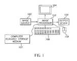
- FIG. 1is a schematic diagram of an image processing system useful in practicing the present invention.
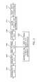
- FIG. 2is a flowchart illustrating the face detection method of the present invention.
- FIG. 3Ais a flowchart illustrating a method of irregular grid pattern design.
- FIG. 3Bis a flowchart illustrating a method of regular grid pattern design.
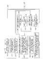
- FIG. 4Ais a flowchart illustrating a detailed process of orientation determination according to the present invention.
- FIG. 4Bis a flowchart illustrating a detailed process of mean grid pattern testing for face orientation determination, as used in the process shown in FIG. 4A .
- FIG. 5is an illustration showing an irregular grid pattern.
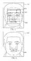
- FIG. 6is an illustration showing key positions for regular grid pattern design.
- FIG. 7is an illustration showing position and size parameters for regular grid pattern design.
- FIG. 8is an illustration of an intensity face image and its regular grid pattern image with exemplary four orientations.
- FIG. 9is a graph illustrating distributions of correlation coefficients for face grid pattern images and the mean face grid pattern image, and non-face grid pattern images and the mean face grid pattern image.
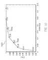
- FIG. 10is a graph illustrating face detection rates and false positive rates as functions of threshold values using the present invention.
- FIGS. 11A and 11Billustrate an intensity image and its associated integral image.
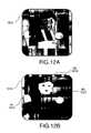
- FIGS. 12A , 12 B, 12 C and 12 Dare illustration useful in describing an image, a skin test and a geometry test and the definition of a box for a skin color cluster respectively.
- FIG. 13is an illustration useful in describing a location test and post-test processing.
- FIG. 14is a chart useful in illustrating the outcomes of exemplary orientation differences between a face grid pattern image and a mean grid pattern image.
- FIG. 15is an illustration of distributions of correlation coefficients for face grid pattern images and mean face grid pattern images having four different orientations.
- FIG. 1which shows an image processing system useful in practicing the present invention, includes a color digital image source 100 , such as a film scanner, a digital camera, or a digital image storage device (e.g., such as a compact disk drive for playing images stored on a Picture CD).
- the digital image from the digital image source 100is provided to an image processor 102 , such as a programmable personal computer, or a digital image processing work station such as a Sun Sparc workstation.
- the image processor 102may be connected to a CRT display 104 , an operator interface such as a keyboard 106 and a mouse 108 .
- the image processor 102is also connected to a computer readable storage medium 107 .
- the image processor 102transmits processed digital images to an output device 109 .
- the output device 109can comprise a hard copy printer, a long-term image storage device, a connection to another processor, or an image telecommunication device connected, for example, to the Internet.
- the present inventionmay also comprise a computer program product for detecting human faces in a digital image in accordance with the method described.
- the computer program of the present inventioncan be utilized by any well-known computer system, such as the personal computer of the type shown in FIG. 1 .
- many other types of computer systemscan be used to execute the computer program of the present invention.
- the method of the present inventioncan be executed in a computer contained in a digital camera. Consequently, the computer system will not be discussed in further detail herein.
- the computer program product of the present inventionmay make use of image manipulation algorithms and processes that are well known. Accordingly, the present description will be directed in particular to those algorithms and processes forming part of, or cooperating more directly with, the method of the present invention. Thus, it will be understood that the computer program product embodiment of the present invention may embody algorithms and processes not specifically shown or described herein that are useful for implementation. Such algorithms and processes are conventional and within the ordinary skill in such arts.
- the computer program for performing the method of the present inventionmay be stored in a computer readable storage medium.
- This mediummay comprise, for example: magnetic storage media such as a magnetic disk (such as a hard drive or a floppy disk) or magnetic tape; optical storage media such as an optical disc, optical tape, or machine readable bar code; solid state electronic storage devices such as random access memory (RAM), or read only memory (ROM); or any other physical device or medium employed to store a computer program.
- the computer program for performing the method of the present inventionmay also be stored on a computer readable storage medium that is connected to the image processor by way of the Internet or other communication medium. Those skilled in the art will readily recognize that the equivalent of such a computer program product may also be constructed in hardware.
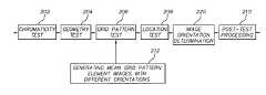
- FIG. 2is a flow chart illustrating one embodiment of the face detection method of the present invention.
- an input color digital imagegoes through a set of cascaded tests. Each of these tests discards non-face objects with high confidence and retains most faces.
- the ideais to maintain a very high true-positive detection rate in every cascaded test while keeping a relatively low false-positive rate for individual tests. Since tests are cascaded, an overall performance of high true-positive and low false-positive rates is achieved.
- face detection tasksare distributed to different types of tests. This distributed system approach reduces the burden on each individual test, thereby, speeding up the detection process.
- a chromaticity test 202discards, with high confidence, non-skin-color pixels in the input digital color image.
- This chromaticity testis different from the traditional skin color detection methods.
- most skin color detection techniquesemploy carefully designed skin color models in order to achieve high skin detection accuracy with very low false positives.
- skin color models having a high degree of accuracyoften tend to exclude skin colors falling outside of the skin color region of a majority population upon which skin color models are built.
- the exclusion of non-majority skin colorsresults in face detection failures.
- This chromaticity testinstead, focuses on exclusion of non-skin-colors with high accuracy. For example, it discards (sets to black) saturated green, or saturated blue pixels, and keeps pixels having colors close to skin-colors of all hues. Therefore, it does not reject skin color pixels of non-majority populations.
- the chromaticity test 202is followed by a geometry test 204 .
- Pixels retained in the chromaticity test step 202are grouped into regions (or clusters of pixels). These regions are checked to see if they pass a geometry test. Only those regions that pass the test will be allowed to enter a subsequent statistical test, that is, a grid pattern test 206 ; all other pixels are set to black.
- the geometry test 204basically checks a region's geometric shape, size, and location.
- the grid pattern test 206performs the task of locating actual faces with the help of a mean grid pattern element image that is formed in a mean grid pattern element image generator 212 .
- the grid pattern test 206performs a similarity check by evaluating a correlation coefficient between the mean grid pattern element image and a grid pattern element image generated from a sub-image that is cropped from the remaining regions obtained from the geometry test step 204 .
- Sub-images that pass the grid pattern test 206are marked as candidate faces and assigned an orientation index. Some candidates may reside partially in regions discarded in the geometry test 204 .
- All candidatesare subsequently checked in a location test 208 .
- Candidates residing partially in regions discarded in the geometry test 204are unmarked in the location test 208 .
- the grid pattern test 206is performed on the image in a raster scan fashion. Raster scanning, however, may result in multiple candidates very close to each other in terms of position for the same face.
- Post-test processing 210is then performed to combine closely spaced multiple candidates into a single candidate based on a distance measure. Every one of the resultant candidates is given an orientation index. The image orientation is thus determined in an image orientation determination stage 220 based on the candidates' orientation indices.
- an input image having a standard sizemay first be resized downward in a resizing image down step 402 .
- This stepis optional to increase the processing speed of the method.
- An exemplary standard size input imagecould be 384 ⁇ 256 pixels.
- An exemplary resizing factoris 4. The purpose of resizing downward of the input image is to speed up the processes of the chromaticity test 202 and the geometry test 204 .
- the resized color imageis processed in an erasing non-skin-color pixels step 404 (referred to as a chromaticity test 202 in FIG. 2 ) to get rid of non-skin-color pixels.
- the non-skin color pixelsare set to black. Unlike traditional skin color detection algorithms, this chromaticity test has neither color space conversion nor skin color modeling. In the present invention, if a pixel satisfies a set of conditions, it will be marked as a non-skin-color pixel.
- Equation (1)rowsnew and colsnew are the height and width of the resized image; r, g, b are three color components of a pixel, Rgratio 1 , Rbratio 1 , Rgratio 2 , and Rbratio 2 are predefined coefficients, and Rt, Gt and Bt are absolute values used as predefined thresholds.
- FIGS. 12A–Dshow an example of a chromaticity test.
- FIG. 12Athere is an intensity color image 1202 .
- FIG. 12Bthere is a first binary image 1212 that is the result after applying Equation (1) to the intensity image 1202 .
- a pixel in darkrepresents a non-skin-color pixel in the intensity image 1202
- a pixel in whiterepresents a skin-color pixel in the intensity image 1202 .
- step 406 of clustering remaining pixels into regionsthere are three steps (step 406 of clustering remaining pixels into regions, step 408 of morphological processing, and step 410 of erasing unwanted regions) responsible for implementing the geometry test 204 .
- step 406 of clustering remaining pixels into regionsis a binary image obtained from the chromaticity test 202 in FIG. 2 (or the step 404 of erasing non-skin-color pixels in the more detailed flow chart shown in FIG. 4A ).
- An example binary imageis shown in the upper right part of FIG. 12B . Non-zero pixels in the first binary image 1212 are grouped into clusters.
- a clusteris a non-empty set of non-black pixels with the property that any pixel within the cluster is also within a predefined distance to another pixel in the cluster.
- An exemplary predefined distanceis 1 pixel of the resized image.
- Example clusters in the first binary image 1212are cluster R 1 ( 1216 ), cluster R 2 ( 1218 ), and cluster R 3 ( 1220 ).
- cluster R 1 ( 1216 )is a combination of two barely touching clusters.
- cluster RI ( 1216 ) in the binary image 1212breaks into two clusters R 11 ( 1234 ) and R 12 ( 1236 ) in a second binary image 1232 ( FIG. 12C ).
- a preferred morphological processis an opening/closing operation.
- the morphological operation in the geometry test stepis implemented by evaluating the 8-connected neighbors of a non-zero pixel and deleting this pixel if the number of zero valued neighbors exceeds a threshold.
- the currently used threshold, T Mis 5 and threshold is adjustable from application to application.
- a final step in the geometry test 204is the step 410 of erasing unwanted clusters step.
- Unwanted clustersare those clusters satisfying one or more of the following conditions: (1) the maximum width of a cluster is smaller than a predefined minimum width; (2) the maximum height of a cluster is smaller than a predefined minimum height; (3) the center of a cluster is within a minimum margin of the image boundary.
- An exemplary predefined minimum widthis 3 pixels of the resized image.
- An exemplary predefined minimum heightis 3 pixels of the resized image.
- An exemplary predefined minimum marginis 3 pixels of the resized image.
- Examples of clusters to be erasedare cluster R 2 ( 1238 ), cluster R 11 ( 1234 ) and cluster R 4 ( 1240 ) in the second binary image 1232 in FIG. 12C .
- the result of the step 410 of erasing unwanted clustersis a third binary image 1242 shown in FIG. 12D . Examples of remaining clusters are R 3 ( 1244 ) and R 12
- the test after the geometry test 204is the grid pattern test 206 , which is also identified as test 440 in FIG. 4A .
- the grid pattern test 206( 440 ) starts from a step 414 of cropping a sub-image using a set of parameters and ends with a query 3 ( 430 ).
- An intensity image to be used in the grid pattern test 206is a gray scale image converted from the original color image in a step 411 of converting to gray image shown in FIG. 4A .
- the parameters used in the cropping a sub-image step 414are generated in a step 412 of forming a parameters sets list.
- a set of parameterscontains a width, a height, and positions of an upper left corner of a rectangular box.
- the width of the boxis a maximum width of a cluster retained in the geometry test 204
- the height of the boxis a maximum height of a cluster retained in the geometry test 204 .
- An example of such a boxis a box 1248 shown in FIG. 12D .
- the positions of the upper left corner of the boxare defined with respect to the upper left corner of the binary image 1242 . It should be understood that these parameters are re-scaled to fit the original standard image size before they are used to crop a sub-image from the gray scale image in the step 414 of cropping a sub-image.
- the grid pattern test 206uses a mean grid pattern element (MGPe) image generated in mean grid pattern element image generator 212 .
- MGPemean grid pattern element
- Design 1is a generalized design.
- Design 2is a special case of design 1 .
- the steps for implementing design 1are described in FIG. 3A .
- a first step in design 1is a step 304 of collecting sample face images. A large number of cropped face images are manually collected.
- a mean face imageis obtained by aligning two eyes of all the collected face images and taking an average intensity for every pixel. For the mean grid pattern element image.
- the mean face imageis divided into a grid pattern comprising a plurality of cells.
- the grid cell sizes and positionsare manually determined.
- the grid patternis irregular in that the cells have different sizes and each one of them covers a specific area of the face cluster (step 308 of determining individual cells covering local facial features).
- An example of such an irregular cell design (cell design 1 )is shown in FIG. 5 .
- a cell 506covering the forehead area.
- Other examples of cell design 1can also be seen in FIG. 5 .
- a smallest box that contains all the cellsis determined in a step 310 of determining a box containing all cells.
- An example box 508is shown in FIG. 5 .
- a sub-image of the mean face imagecan be obtained in a step 312 of cropping a sub-image.
- Four corner dots (position coordinates)such as an upper right corner dot 504 of the cell 506 are thereby calculated with respect to the upper left corner of the sub-image in a step 314 of determining four cell corner positions.
- FIG. 11An efficient approach to compute a mean grid pattern element image is to use an integral image (see “Robust real-time object detection”, by Paul Viola et al., Proceedings of ICCV 2002, which is incorporated herein by reference and may be referenced for a detailed discussion of the calculation of an integral image).
- image A ( 1102 )is a gray level intensity image
- image B ( 1122 )is an integral image of image A ( 1102 ).
- the integral imagehas the same size as the mean face intensity image.
- the computation of a pixel 1126 in integral image B ( 1122 )is
- Equation (2)is replaced by a pair of recurrences introduced in Viola's paper for speedy computation.
- a mean grid pattern imageis computed in a step 318 of computing a mean grid pattern image using cell corner positions in the integral image.
- the mean grid pattern imagehas the same size as the mean face intensity image.
- the mean grid pattern element imageis extracted from the mean grid pattern image.
- FIG. 11there is a cell 1116 defined by four corner points p 1 ( 1108 ), p 2 ( 1110 ), p 3 ( 1112 ), and p 4 ( 1114 ). This cell covers a nose area of the mean face image. This cell also represents a cell in the same position in the mean grid pattern image to be computed from the mean face image. The computation of any pixels in this cell for the mean grid pattern image is expressed as
- ⁇1 m ⁇ ⁇ n ⁇ ( B ⁇ ( p 4 ′ ) + B ⁇ ( p 1 ′ ) - B ⁇ ( p 2 ′ ) - B ⁇ ( p 3 ′ ) ) ⁇ ⁇ ⁇ ⁇ ⁇ [ p 1 , p 2 , p 3 , p 4 ] ( 3 )
- ⁇ [p 1 ,p 2 ,p 3 ,p 4 ]is the cell defined by four corner points p 1 ( 1108 ), p 2 ( 1110 ), p 3 ( 1112 ), and p 4 ( 1114 ) in the grid pattern image
- ⁇is any pixel in cell ⁇ [p 1 ,p 2 ,p 3 ,p 4 ]
- B(p′ x )is the pixel value at positions p′ x (they are p′ 1 ( 1128 ), p′ 2 ( 1130 ), p′ 3 ( 1132 ), and p′ 4 (
- the format of the mean grid pattern element imagecould be a one dimensional image or a two dimensional image.
- a preferred formatis the one dimensional image.
- For constructing the mean grid pattern element imagesimply copy one pixel from each of the cells of the mean grid pattern image to a pixel in the mean grid pattern element image in an order.
- the number of pixels in the mean grid pattern element (MGPe) imageequals the number of cells in the mean grid pattern image.
- the order of pixel copying process for this operationneeds to be recorded so that in the grid pattern test 206 the same order can be used to form a grid pattern element image for images under testing if design 1 is selected.
- one of the four orientations (north, east, south, and west) of a face candidateis to be determined using the MGPe image.
- the elements of the MGPe image generated in step 212is reordered to form a new MGPe image with a different orientation.
- four different MGPe images with different orientationscan be pre-generated in step 212 .
- denote the MGPe images with different orientationsby ⁇ 0 i , where i ⁇ [1,2,3,4].
- Denote a first orientation MGPe image by ⁇ 0 1An exemplary first orientation is shown in FIG. 5 when the face is upright.
- a second orientation MGPe imageby ⁇ 0 2 .
- An exemplary second orientationis clock-wise rotated first orientation.
- a third orientation MGPe imageby ⁇ 0 3 .
- An exemplary third orientationis upside down turned first orientation.
- a fourth orientation MGPe imageby ⁇ 0 4 .
- An exemplary fourth orientationis counter clock-wise rotated first orientation.
- MGPemean grid pattern element
- a first step in design 2is a step 372 of collecting sample face images in FIG. 3B .
- a large number of cropped face imagesare manually collected.
- a mean face imageis obtained by aligning two eyes of all the collected face images and taking an average intensity for every pixel.
- grid cell sizes and positionshave to be determined.
- all cellshave the same size.
- the designstarts at a step 376 of computing a distance e 1 ( 608 in a face image 602 in FIG. 6 ) between two eye centers.
- center position c ( 706 in a face image 702 in FIG. 7 ) between the two eye centersin a step 378 of computing a center position.
- FIG. 7starting from the center c ( 706 ), there are four arrows (arrow 704 , arrow 708 , arrow 710 and arrow 712 ) pointing north, east, south and west respectively.
- Tips of the arrowsdefine boundaries of a box to be used to crop the mean face image in order to compute the MGPe image.
- the upper boundaryis (M ⁇ 1 ) units (u) away from the center c
- the lower boundaryis (M+ ⁇ 2 ) units (u) away from the center
- left boundaryis N units (u) away from the center
- right boundaryis N units (u) away from the center.
- the physical length of unit udepends on the size of the mean face image.
- An exemplary value for Mis 7, for N is 7, for ⁇ 1 is 2, and for ⁇ 2 is 2. In this case, as shown in FIG.
- the designhas square cells (such as cell 806 ) all having a same size and a square cropping region used in a step 382 of cropping a sub-image (see the cropped sub-image 802 from the mean face image shown in FIG. 8 ).
- positions of four corners of a cell 806can be easily calculated with respect to the upper left corner of the sub-image in a step 384 of determining four corner positions.
- subsequent stepsstep 386 of generating an integral image, step 388 of computing a mean grid pattern image and step 390 of generating a mean grid pattern element image) are very much the same as that in design 1 .
- the mean grid pattern element (MGPe) imagetakes only one pixel from each of the cells, statistically, the size of the cropped sub-image (thereby, size of individual cells) should not matter.
- the MGPe imageis simply a statistical measure of main features of a mean face. Practically, an exemplary size for the cropped sub-image for design 2 could be 105 ⁇ 10 5 with 7 ⁇ 7 cells each of which has 15 ⁇ 15 pixels. Thereby, the mean grid pattern element (MGPe) image has 49 elements.
- an MGPe imagegathers the statistical information (structural information and intensity information) of a mean face region.
- a type of measurehas to be determined.
- a statistical correlation coefficient(see The Statistical Analysis of Time Series by T. W. Anderson, John Wiley & Sons, Inc, 1994, chapter 6 , which is incorporated herein by reference) of two variables is used for classifying faces or non-face objects.
- the two variableshere are a mean grid pattern element (MGPe) image and a grid pattern element (GPe) image of an image under testing.
- the GPe imageshould have the same size as the MGPe image.
- the correlation coefficient ras a statistical measure to separate non-face objects and faces, distributions of the correlation coefficients between MPGe of the mean face and GPe of faces and the correlation coefficients between MPGe of the mean face and GPe of non-face objects are inspected.
- a large number of sample faces with a same orientationare used to generate face grid pattern element (GPe) images using the method described in design 2 above (step 376 through step 390 in FIG. 3B ). Note that this time, a GPe image is generated for each individual sample face image, not for a mean image.
- Equation (4)is applied to the MGPe image of the same orientation of the faces and each of the individual face GPe images.
- a large number of correlation coefficientsare produced.
- An example distribution of these coefficientsis depicted in FIG. 9 by a curve 906 in chart 902 . Noticeably, for face GPe images, the correlation coefficients are mostly distributed between 0.4 to 1. The same procedures can be applied to a large number of non-face sample images.
- FIG. 9An example distribution of correlation coefficients between the MGPe image and the non-face GPe images is depicted in FIG. 9 by a curve 904 in chart 902 .
- the correlation coefficientsare mostly distributed below 0.4. Therefore, by changing a threshold r T ( 908 ), a balanced true positive (correctly classified face) verses false positive (falsely classified face) performance is achievable.
- Chart 1002 in FIG. 10shows a curve 1004 that depicts the performance of true positives verses false positives as a function of the threshold r T ( 908 ).
- a threshold value 0.3confirms approximately 97.8% of the faces from the sample face set, while the same threshold falsely accepts roughly 6.2% of the non-faces from the non-face set as faces.
- p(r ij )is the correlation coefficient distribution between ⁇ 0 1 and ⁇ 1 1 images.
- distribution p(r 11 ) ( 1514 )mostly locates close to positive 1, since the testing GPe images and the MGPe image have the same orientation.
- distributions p(r 12 ), p(r 13 ), and p(r 14 )locate away from positive 1, because ⁇ 1 2 , images, ⁇ 1 3 images, and ⁇ 1 4 images are not in the same orientation as ⁇ 0 1 , and they are treated as non-faces by ⁇ 0 1 .
- Outcomes 1416 and 1418have a near zero positive mean value when the two operands of the correlation operation C( ⁇ 0 i , ⁇ 1 j ) are misaligned (90° or ⁇ 90° difference indicated by dot 1408 and 1410 ).
- Outcome 1420has relatively a higher negative mean value when the two operands of the correlation operation C( ⁇ 0 i , ⁇ 1 j ) are misaligned (180° difference indicated by dot 1412 ).
- the grid pattern test 206( 440 ) is detailed by a series of steps, i.e., from a step 414 of cropping a sub-image to a query 3 ( 430 ).
- a set of parameterscontains a width, a height, and positions of an upper left corner of a rectangular box.
- the width of the boxis a maximum width of a cluster retained in the geometry test 204
- the height of the boxis a maximum height of a cluster retained in the geometry test 204 .
- An example of such a boxis a box 1248 shown in FIG. 12 .
- the positions of the upper left corner of the boxare defined with respect to the upper left corner of the binary image 1242 . It should be understood that these parameters are re-scaled to fit the original image size before they are used to crop a sub-image from the gray scale image in the step 414 of cropping a sub-image step.
- a sub-imageis cropped from a gray image obtained from a step 411 of converting the gray image. Notice that this gray image has all but pixels retained in the step 410 of erasing unwanted clusters set to black. Notice, parameters from step 410 have to be resealed before they can used in step 411 .
- the gray imagemay have objects such as shown in example image 1242 .
- An example set of parametersmay crop a sub-image having the same size as box 1248 .
- This sub-imagehas a cluster such as R 12 ( 1246 ). This cluster has gray scale pixels. Pixels outside the cluster are black. With this sub-image, a corresponding integral image can be computed in a step 416 of computing an integral image.
- the cropped sub-image of the digital color imagemust be evaluated at a plurality of effective resolutions, which is done by reducing the cropped sub-image to a plurality of grid pattern element images (GPe images) at different effective resolutions and then correlating the MGPe image with the GPe image at each resolution.
- GPe imagesgrid pattern element images
- the search of facesstarts with a maximum possible cell size (see a step 418 of starting from an adequate grid pattern cell size) and continues all the way down to a minimum allowable cell size (see query 2 ( 428 )).
- a 7 ⁇ 7 grid pattern element imagesee grid pattern 804 in FIG. 8 as an example format is used for the face detection.
- the cropped sub-imagehas a size of 70 ⁇ 70 pixels.
- the maximum possible cell sizeis 10 ⁇ 10 pixels in this case (given a 7 ⁇ 7 grid pattern).
- the minimum allowable cell sizeis predefined.
- An exemplary minimum allowable cell sizeis 2 ⁇ 2 pixels.
- a 7 ⁇ 7 grid pattern element imageonly needs a 14 ⁇ 14 pixel region to support cells having a size of 2 ⁇ 2 pixels; consequently there are many possible different search placements of the resulting 7 ⁇ 7 pattern in the 70 ⁇ 70 pixel region.
- the 14 ⁇ 14 support regionwill be stepped through the 70 ⁇ 70 sub-image to cover all the possible grid pattern positions, and there will be 3249 searches for the minimum allowable cell size, that is, if the search step size is 1.
- An exemplary maximum allowable cell sizeis 25 ⁇ 25 pixels.
- the difference between two consecutive cell sizescan be determined by a predefined scale factor.
- An exemplary scale factorcould be 2 1/8 .
- the grid pattern testbasically correlates a set of MGPe images with different orientations to a GPe image obtained from the test image.
- the different orientationsmay be applied to the grid pattern element (GPe) image for purpose of the test rather than to the mean grid pattern element (MGPe) image, i.e., the grid pattern test may correlate an MGPe image to a set of GPe images with different orientations, as initially obtained (at an initial orientation) from the test image.
- MGPemean grid pattern element
- a step 420 of scanning the current sub-imagecrops a patch of the integral image computed from the cropped sub-image in step 416 .
- a step 482which involves choosing an orientation, selecting a mean grid pattern element image and computing a grid pattern element image of the scanned area using the integral image, an irregular type MGPe image with a certain orientation is selected first. Then, the cropped patch of the integral image is used to compute an irregular type grid pattern element (GPe) image with the same orientation.
- GPeirregular type grid pattern element
- a testis performed to see if a patch of the sub-image corresponding to the cropped integral image patch represents a face by evaluating a correlation coefficient of the GPe image and the MGPe image.
- the position and size parameters (denoted by P) of the current patch along with the orientation index (denoted by o i , i ⁇ [1,2,3,4]) and correlation coefficient rare added into face-like pattern object candidates list in a step 424 of condition checking.
- a step 420 of scanning the current sub-imagecrops a patch of the integral image computed from the cropped sub-image in step 416 .
- a regular type MGPe image with a certain orientationis selected first. Then, the cropped patch of the integral image is used to compute a regular type grid pattern element (GPe) image.
- a testis performed to see if a patch of the sub-image corresponding to the cropped GPe image patch represents a face by evaluating a correlation coefficient of the GPe image and the MGPe image.
- the position and size parameters (denoted by P) of the current patch along with the orientation index (denoted by o i , i ⁇ [1,2,3,4]) and correlation coefficient rare added into a face-like pattern object candidates list in a step 424 of condition checking.
- the above described grid pattern testis performed for all orientations (see query 0 ( 484 )), for all areas within a cropped sub-image (see query 1 ( 426 )), for all adequate cell sizes (see query 2 ( 428 )), and for all parameter sets (see query 3 ( 430 )).
- Nthere is a limit N on the number of face-like pattern object candidates that can be added to the list.
- An exemplary value for the limit Nis 10.
- the listis first filled with N candidates and rank ordered according to their correlation coefficient (r) values.
- the candidate having the highest ris arranged at the top of the list.
- Any subsequent qualified candidate(with r ⁇ r T ) is compared with the candidates that are already in the list. If the correlation coefficient value of the new candidate is lower than the candidate at the bottom of the list, the new candidate is discarded. Otherwise, the new candidate will be inserted to the list and the candidate at the bottom of the list will be pushed out from the list.
- the actual number of qualified candidates in a listis usually equal to or less than N.
- the maximum number of qualified candidates for an image, ⁇ ,is nN, where n is the number of cropped sub-images.
- a step of location testing 432tests the face candidate areas defined by the stored parameters. This testing removes a set of parameters from the face candidates list if the area defined by the set of parameters contains less than a predefined percentage of a cluster retained in step 410 .
- An exemplary candidate to be removedis shown in FIG. 13 .
- Candidate W 1 ( 1306 )partially covers a face area, so it is removed from the candidate list.
- the final number of face-like pattern object candidates, ⁇ circumflex over (N) ⁇is equal to or less than ⁇ .
- an image orientation determination stage 220(also 486 ).
- An x % of the ⁇ circumflex over (N) ⁇ number of candidatesare picked for analysis.
- the x % ⁇ circumflex over (N) ⁇ candidatesare the ones having higher r values than all the rest (1 ⁇ x %) ⁇ circumflex over (N) ⁇ candidates.
- An exemplary x valuewould be 10.
- the image orientationis determined calling a vote among the x % ⁇ circumflex over (N) ⁇ most powerful candidates. The majority wins. If there is a tie, the most powerful candidate sets the orientation.
- a final step of post-test processing 434updates the face candidates parameters list revised in step 432 by merging neighboring candidates based on a distance measure of the centers of the candidate areas.
- Exemplary candidates W 2 ( 1304 ) and W 3 ( 1308 ) in FIG. 13are close to each other, so they are to be merged.
- An exemplary distance measureis a Euclidean distance of one half of the average of the box (candidate areas) heights. For an image there may be M merged candidates, where M ⁇ circumflex over (N) ⁇ in general.
- the subject matter of the present inventionrelates to digital image understanding technology, which is understood to mean technology that digitally processes a digital image to recognize and thereby assign useful meaning to human understandable objects, attributes or conditions, and then to utilize the results obtained in the further processing of the digital image.
Landscapes
- Engineering & Computer Science (AREA)
- Physics & Mathematics (AREA)
- Health & Medical Sciences (AREA)
- Oral & Maxillofacial Surgery (AREA)
- General Health & Medical Sciences (AREA)
- Human Computer Interaction (AREA)
- General Physics & Mathematics (AREA)
- Multimedia (AREA)
- Theoretical Computer Science (AREA)
- Geometry (AREA)
- Image Analysis (AREA)
Abstract
Description
| for(i = 0; i < rowsnew * colsnew; i + +) { | |
| if(r[i] < Rgratio1 * g[i] || r[i] < Rbratiol * b[i]) | |
| || r[i] < Rt || g[i] < Gt || b[i] < Bt || r[i] > RGratio2 * g[i] || | |
| r[i] > RBratio2 * b[i] { | (1) |
| g[i] = 0; | |
| } | |
| } | |
where A(pi)|∥p
where Φ[p1,p2,p3,p4] is the cell defined by four corner points p1(1108), p2(1110), p3(1112), and p4(1114) in the grid pattern image, Φ is any pixel in cell Φ[p1,p2,p3,p4], B(p′x) is the pixel value at positions p′x(they are p′1(1128), p′2(1130), p′3(1132), and p′4(1134)) in the integral image (here, p1=p′1, p2=p′2, p3=p′3, and p4=p′4), m is the cell height and n is the cell width. In this manner, the resolution of the mean face image is reduced to the resolution of the selected grid pattern by the averaging process expressed in equation (3).
r=μ11/σΦ
where
μ11=E{ΦiΦj}−E{Φi}E{Φj} (5)
σ2Φk=E{(Φk−E{Φk})2}
here E{ } is an expectation operator.
- 100 image source
- 102 image processor
- 104 image display
- 106 keyboard
- 107 computer readable storage medium
- 108 mouse
- 109 output device
- 202 chromaticity test
- 204 geometry test
- 206 grid pattern
- 208 location test
- 210 post-test processing
- 212 mean grid pattern element image generator
- 220 orientation determination stage
- 304 collecting sample face images step
- 306 getting a mean face image step
- 308 determining individual cells step
- 310 determining a region containing all cells step
- 312 cropping a sub-image step
- 314 determining four corner positions step
- 316 generating an integral image step
- 318 computing a mean grid pattern image step
- 320 generating a mean grid pattern element image step
- 372 collecting sample face images step
- 374 mean face image step
- 376 computing an eye center distance step
- 378 computing an eye center position step
- 380 region defining step
- 382 cropping a sub-image step
- 384 determining four corner positions step
- 386 generating an integral image step
- 388 computing a mean grid pattern image step
- 390 generating a mean grid pattern element image step
- 402 resizing image down step
- 404 erasing non-skin-color pixels step
- 406 clustering remaining pixels into regions step
- 408 morphological processing step
- 410 erasing unwanted regions step
- 411 converting to gray image step
- 412 forming a parameters sets list step
- 414 cropping a sub-image step
- 416 computing an integral image step
- 418 adequate grid pattern cell size step
- 420 scanning the current sub-image step
- 422 grid pattern testing step
- 424 condition checking step
- 426
query 1 - 428
query 2 - 430
query 3 - 432 location testing step
- 434 post-test processing
- 440 grid pattern test
- 482 select an orientation step
- 484
query 0 - 486 orientation determination step
- 502 face image
- 504 upper right corner dot
- 506 cell
- 508 cluster boundary
- 602 face image
- 608 distance
- 702 face image
- 704 distance
- 706 center position
- 708 distance
- 710 distance
- 712 distance
- 802 face intensity image
- 804 face M×N grid pattern image
- 806 grid cell
- 814 face M×N grid pattern image
- 824 face M×N grid pattern image
- 834 face M×N grid pattern image
- 902 chart
- 904 distribution curve
- 906 distribution curve
- 908 threshold
- 1002 chart
- 1004 curve
- 1006 number
- 1102 mean face image
- 1104 region
- 1106 corner position
- 1108 corner position
- 1110 corner position
- 1112 corner position
- 1114 corner position
- 1116 cell
- 1120 pixel
- 1122 integral image
- 1126 pixel
- 1128 position
- 1130 position
- 1132 position
- 1134 position
- 1202 intensity color image
- 1212 first binary image
- 1216 cluster R1
- 1218 cluster R2
- 1220 cluster R3
- 1232 second binary image
- 1234 cluster R11
- 1236 cluster R12
- 1238 cluster R2
- 1240 cluster R4
- 1242 third binary image
- 1244 cluster R3
- 1246 cluster R12
- 1248 box
- 1302 fourth binary image
- 1304 box W2
- 1306 box W1
- 1308 box W3
- 1310 cluster R3
- 1406 0 degree position
- 1408 90 degree position
- 1410 −90 degree position
- 1412 180 degree position
- 1414 arrow
- 1416 arrow
- 1418 arrow
- 1420 arrow
- 1514 distribution curve
- 1516 distribution curve
- 1518 distribution curve
- 1520 distribution curve
Claims (29)
Priority Applications (1)
| Application Number | Priority Date | Filing Date | Title |
|---|---|---|---|
| US10/354,837US7120279B2 (en) | 2003-01-30 | 2003-01-30 | Method for face orientation determination in digital color images |
Applications Claiming Priority (1)
| Application Number | Priority Date | Filing Date | Title |
|---|---|---|---|
| US10/354,837US7120279B2 (en) | 2003-01-30 | 2003-01-30 | Method for face orientation determination in digital color images |
Publications (2)
| Publication Number | Publication Date |
|---|---|
| US20040151371A1 US20040151371A1 (en) | 2004-08-05 |
| US7120279B2true US7120279B2 (en) | 2006-10-10 |
Family
ID=32770432
Family Applications (1)
| Application Number | Title | Priority Date | Filing Date |
|---|---|---|---|
| US10/354,837Expired - Fee RelatedUS7120279B2 (en) | 2003-01-30 | 2003-01-30 | Method for face orientation determination in digital color images |
Country Status (1)
| Country | Link |
|---|---|
| US (1) | US7120279B2 (en) |
Cited By (63)
| Publication number | Priority date | Publication date | Assignee | Title |
|---|---|---|---|---|
| US20040161166A1 (en)* | 2003-02-19 | 2004-08-19 | Hiromichi Enomoto | Image processing method, image processing apparatus, storage medium and program |
| US20050058369A1 (en)* | 2003-09-09 | 2005-03-17 | Fuji Photo Film Co., Ltd. | Apparatus, method and program for generating photo card data |
| US20050180612A1 (en)* | 2004-01-27 | 2005-08-18 | Toshinori Nagahashi | Method of correcting deviation of detection position for human face, correction system, and correction program |
| US20050234324A1 (en)* | 2004-03-31 | 2005-10-20 | Fuji Photo Film Co., Ltd. | Image display control apparatus and method, and program for controlling image display control apparatus |
| US20060039587A1 (en)* | 2004-08-23 | 2006-02-23 | Samsung Electronics Co., Ltd. | Person tracking method and apparatus using robot |
| US20060115172A1 (en)* | 2004-11-30 | 2006-06-01 | Qian Lin | Face enhancement in a digital video |
| US20070201724A1 (en)* | 2006-02-24 | 2007-08-30 | Eran Steinberg | Method and Apparatus for Selective Disqualification of Digital Images |
| US20070201725A1 (en)* | 2006-02-24 | 2007-08-30 | Eran Steinberg | Digital Image Acquisition Control and Correction Method and Apparatus |
| US20080013800A1 (en)* | 2003-06-26 | 2008-01-17 | Fotonation Vision Limited | Method of Improving Orientation and Color Balance of Digital Images Using Face Detection Information |
| US20080109397A1 (en)* | 2002-07-29 | 2008-05-08 | Rajeev Sharma | Automatic detection and aggregation of demographics and behavior of people |
| US20080181502A1 (en)* | 2007-01-31 | 2008-07-31 | Hsin-Ming Yang | Pattern recognition for during orientation of a display device |
| US20090003661A1 (en)* | 2007-02-28 | 2009-01-01 | Fotonation Vision Limited | Separating a Directional Lighting Variability In Statistical Face Modelling Based On Texture Space Decomposition |
| US20090190803A1 (en)* | 2008-01-29 | 2009-07-30 | Fotonation Ireland Limited | Detecting facial expressions in digital images |
| US20090245649A1 (en)* | 2008-03-25 | 2009-10-01 | Seiko Epson Corporation | Method, Program and Apparatus for Detecting Object, Computer Readable Recording Medium Storing Object Detection Program, and Printing Apparatus |
| US20090263022A1 (en)* | 2006-08-11 | 2009-10-22 | Fotonation Vision Limited | Real-Time Face Tracking in a Digital Image Acquisition Device |
| US7616233B2 (en) | 2003-06-26 | 2009-11-10 | Fotonation Vision Limited | Perfecting of digital image capture parameters within acquisition devices using face detection |
| US7620218B2 (en) | 2006-08-11 | 2009-11-17 | Fotonation Ireland Limited | Real-time face tracking with reference images |
| US7634109B2 (en) | 2003-06-26 | 2009-12-15 | Fotonation Ireland Limited | Digital image processing using face detection information |
| US7684630B2 (en) | 2003-06-26 | 2010-03-23 | Fotonation Vision Limited | Digital image adjustable compression and resolution using face detection information |
| US7693311B2 (en) | 2003-06-26 | 2010-04-06 | Fotonation Vision Limited | Perfecting the effect of flash within an image acquisition devices using face detection |
| US7715597B2 (en) | 2004-12-29 | 2010-05-11 | Fotonation Ireland Limited | Method and component for image recognition |
| US20100226584A1 (en)* | 2009-03-06 | 2010-09-09 | Cyberlink Corp. | Method of Grouping Images by Face |
| US20100238191A1 (en)* | 2009-03-19 | 2010-09-23 | Cyberlink Corp. | Method of Browsing Photos Based on People |
| US20100278385A1 (en)* | 2009-04-30 | 2010-11-04 | Novatek Microelectronics Corp. | Facial expression recognition apparatus and facial expression recognition method thereof |
| US7844135B2 (en) | 2003-06-26 | 2010-11-30 | Tessera Technologies Ireland Limited | Detecting orientation of digital images using face detection information |
| US7844076B2 (en) | 2003-06-26 | 2010-11-30 | Fotonation Vision Limited | Digital image processing using face detection and skin tone information |
| US7855737B2 (en) | 2008-03-26 | 2010-12-21 | Fotonation Ireland Limited | Method of making a digital camera image of a scene including the camera user |
| US7916897B2 (en) | 2006-08-11 | 2011-03-29 | Tessera Technologies Ireland Limited | Face tracking for controlling imaging parameters |
| US7916971B2 (en) | 2007-05-24 | 2011-03-29 | Tessera Technologies Ireland Limited | Image processing method and apparatus |
| US7953251B1 (en) | 2004-10-28 | 2011-05-31 | Tessera Technologies Ireland Limited | Method and apparatus for detection and correction of flash-induced eye defects within digital images using preview or other reference images |
| US7962629B2 (en) | 2005-06-17 | 2011-06-14 | Tessera Technologies Ireland Limited | Method for establishing a paired connection between media devices |
| US7965875B2 (en) | 2006-06-12 | 2011-06-21 | Tessera Technologies Ireland Limited | Advances in extending the AAM techniques from grayscale to color images |
| US20110181746A1 (en)* | 2010-01-25 | 2011-07-28 | Apple Inc. | Image Preprocessing |
| US20110182507A1 (en)* | 2010-01-25 | 2011-07-28 | Apple Inc. | Image Preprocessing |
| US20110182503A1 (en)* | 2010-01-25 | 2011-07-28 | Apple Inc. | Image Preprocessing |
| US20110182509A1 (en)* | 2010-01-25 | 2011-07-28 | Apple Inc. | Image Preprocessing |
| US8050465B2 (en) | 2006-08-11 | 2011-11-01 | DigitalOptics Corporation Europe Limited | Real-time face tracking in a digital image acquisition device |
| US8050466B2 (en) | 2006-08-02 | 2011-11-01 | DigitalOptics Corporation Europe Limited | Face recognition with combined PCA-based datasets |
| US8055067B2 (en) | 2007-01-18 | 2011-11-08 | DigitalOptics Corporation Europe Limited | Color segmentation |
| US8155397B2 (en) | 2007-09-26 | 2012-04-10 | DigitalOptics Corporation Europe Limited | Face tracking in a camera processor |
| US8165354B1 (en)* | 2008-03-18 | 2012-04-24 | Google Inc. | Face recognition with discriminative face alignment |
| US8189927B2 (en) | 2007-03-05 | 2012-05-29 | DigitalOptics Corporation Europe Limited | Face categorization and annotation of a mobile phone contact list |
| US8199979B2 (en) | 2004-01-22 | 2012-06-12 | DigitalOptics Corporation Europe Limited | Classification system for consumer digital images using automatic workflow and face detection and recognition |
| US8213737B2 (en) | 2007-06-21 | 2012-07-03 | DigitalOptics Corporation Europe Limited | Digital image enhancement with reference images |
| US8330831B2 (en) | 2003-08-05 | 2012-12-11 | DigitalOptics Corporation Europe Limited | Method of gathering visual meta data using a reference image |
| US8345114B2 (en) | 2008-07-30 | 2013-01-01 | DigitalOptics Corporation Europe Limited | Automatic face and skin beautification using face detection |
| US8363951B2 (en) | 2007-03-05 | 2013-01-29 | DigitalOptics Corporation Europe Limited | Face recognition training method and apparatus |
| US8379917B2 (en) | 2009-10-02 | 2013-02-19 | DigitalOptics Corporation Europe Limited | Face recognition performance using additional image features |
| US8488023B2 (en) | 2009-05-20 | 2013-07-16 | DigitalOptics Corporation Europe Limited | Identifying facial expressions in acquired digital images |
| US8494286B2 (en) | 2008-02-05 | 2013-07-23 | DigitalOptics Corporation Europe Limited | Face detection in mid-shot digital images |
| US8498452B2 (en) | 2003-06-26 | 2013-07-30 | DigitalOptics Corporation Europe Limited | Digital image processing using face detection information |
| US8503800B2 (en) | 2007-03-05 | 2013-08-06 | DigitalOptics Corporation Europe Limited | Illumination detection using classifier chains |
| US8553949B2 (en) | 2004-01-22 | 2013-10-08 | DigitalOptics Corporation Europe Limited | Classification and organization of consumer digital images using workflow, and face detection and recognition |
| US8593542B2 (en) | 2005-12-27 | 2013-11-26 | DigitalOptics Corporation Europe Limited | Foreground/background separation using reference images |
| US8649604B2 (en) | 2007-03-05 | 2014-02-11 | DigitalOptics Corporation Europe Limited | Face searching and detection in a digital image acquisition device |
| US8675991B2 (en) | 2003-06-26 | 2014-03-18 | DigitalOptics Corporation Europe Limited | Modification of post-viewing parameters for digital images using region or feature information |
| US8682097B2 (en) | 2006-02-14 | 2014-03-25 | DigitalOptics Corporation Europe Limited | Digital image enhancement with reference images |
| US8687078B2 (en) | 2008-12-05 | 2014-04-01 | DigitalOptics Corporation Europe Limited | Face recognition using face tracker classifier data |
| US20140147021A1 (en)* | 2012-11-27 | 2014-05-29 | Nokia Corporation | Method and apparatus for facilitating interaction with an object viewable via a display |
| US8989453B2 (en) | 2003-06-26 | 2015-03-24 | Fotonation Limited | Digital image processing using face detection information |
| US9129381B2 (en) | 2003-06-26 | 2015-09-08 | Fotonation Limited | Modification of post-viewing parameters for digital images using image region or feature information |
| US9692964B2 (en) | 2003-06-26 | 2017-06-27 | Fotonation Limited | Modification of post-viewing parameters for digital images using image region or feature information |
| CN109033923A (en)* | 2017-06-08 | 2018-12-18 | 北京君正集成电路股份有限公司 | The method and device of human body direction in a kind of detection picture |
Families Citing this family (16)
| Publication number | Priority date | Publication date | Assignee | Title |
|---|---|---|---|---|
| CA2524390C (en)* | 2003-04-04 | 2012-06-05 | Angstrom Technologies, Inc. | Methods and ink compositions for invisibly printed security images having multiple authentication features |
| US7295703B2 (en)* | 2004-06-18 | 2007-11-13 | Xerox Corporation | Method for scanner characterization for color measurement of printed media having four or more colorants |
| JP4845715B2 (en)* | 2006-12-22 | 2011-12-28 | キヤノン株式会社 | Image processing method, image processing apparatus, program, and storage medium |
| FI20075454A0 (en)* | 2007-06-15 | 2007-06-15 | Virtual Air Guitar Company Oy | Statistical object tracking in computer vision |
| WO2009026360A2 (en) | 2007-08-21 | 2009-02-26 | Angstrom Technologies, Inc | Stable emissive toner composition system and method |
| US8094971B2 (en)* | 2007-09-05 | 2012-01-10 | Seiko Epson Corporation | Method and system for automatically determining the orientation of a digital image |
| US9514355B2 (en)* | 2009-01-05 | 2016-12-06 | Apple Inc. | Organizing images by correlating faces |
| US20100254597A1 (en)* | 2009-04-07 | 2010-10-07 | Jonathan Yen | System and method for facial tone indexing |
| US8520956B2 (en)* | 2009-06-09 | 2013-08-27 | Colorado State University Research Foundation | Optimized correlation filters for signal processing |
| CN103119930B (en)* | 2010-10-04 | 2018-04-10 | 日本电气株式会社 | Image display device and image list display method |
| US10169661B2 (en)* | 2014-03-28 | 2019-01-01 | International Business Machines Corporation | Filtering methods for visual object detection |
| JP6849387B2 (en)* | 2016-10-24 | 2021-03-24 | キヤノン株式会社 | Image processing device, image processing system, control method of image processing device, and program |
| JP2021005320A (en)* | 2019-06-27 | 2021-01-14 | 東芝映像ソリューション株式会社 | Image processing system and image processing method |
| CN113538274B (en)* | 2021-07-14 | 2024-12-24 | Oppo广东移动通信有限公司 | Image beautification processing method, device, storage medium and electronic device |
| CN114444657B (en)* | 2021-12-30 | 2025-08-26 | 浪潮电子信息产业股份有限公司 | Image processing method, system, device and readable storage medium |
| CN114399454B (en)* | 2022-01-18 | 2024-10-18 | 平安科技(深圳)有限公司 | Image processing method, device, electronic equipment and storage medium |
Citations (13)
| Publication number | Priority date | Publication date | Assignee | Title |
|---|---|---|---|---|
| US5430809A (en) | 1992-07-10 | 1995-07-04 | Sony Corporation | Human face tracking system |
| US5629752A (en) | 1994-10-28 | 1997-05-13 | Fuji Photo Film Co., Ltd. | Method of determining an exposure amount using optical recognition of facial features |
| US5835616A (en) | 1994-02-18 | 1998-11-10 | University Of Central Florida | Face detection using templates |
| WO1999023600A1 (en) | 1997-11-04 | 1999-05-14 | The Trustees Of Columbia University In The City Of New York | Video signal face region detection |
| US5982912A (en) | 1996-03-18 | 1999-11-09 | Kabushiki Kaisha Toshiba | Person identification apparatus and method using concentric templates and feature point candidates |
| US20010036298A1 (en)* | 2000-02-01 | 2001-11-01 | Matsushita Electric Industrial Co., Ltd. | Method for detecting a human face and an apparatus of the same |
| US6421463B1 (en)* | 1998-04-01 | 2002-07-16 | Massachusetts Institute Of Technology | Trainable system to search for objects in images |
| US20020102024A1 (en)* | 2000-11-29 | 2002-08-01 | Compaq Information Technologies Group, L.P. | Method and system for object detection in digital images |
| US20030108244A1 (en)* | 2001-12-08 | 2003-06-12 | Li Ziqing | System and method for multi-view face detection |
| US20030133613A1 (en)* | 2002-01-15 | 2003-07-17 | Fuji Photo Film Co., Ltd. | Image processing apparatus |
| US20040013304A1 (en)* | 2002-07-22 | 2004-01-22 | Viola Paul A. | System and method for detecting objects in images |
| US20050013479A1 (en)* | 2003-07-16 | 2005-01-20 | Rong Xiao | Robust multi-view face detection methods and apparatuses |
| US6940545B1 (en)* | 2000-02-28 | 2005-09-06 | Eastman Kodak Company | Face detecting camera and method |
- 2003
- 2003-01-30USUS10/354,837patent/US7120279B2/ennot_activeExpired - Fee Related
Patent Citations (13)
| Publication number | Priority date | Publication date | Assignee | Title |
|---|---|---|---|---|
| US5430809A (en) | 1992-07-10 | 1995-07-04 | Sony Corporation | Human face tracking system |
| US5835616A (en) | 1994-02-18 | 1998-11-10 | University Of Central Florida | Face detection using templates |
| US5629752A (en) | 1994-10-28 | 1997-05-13 | Fuji Photo Film Co., Ltd. | Method of determining an exposure amount using optical recognition of facial features |
| US5982912A (en) | 1996-03-18 | 1999-11-09 | Kabushiki Kaisha Toshiba | Person identification apparatus and method using concentric templates and feature point candidates |
| WO1999023600A1 (en) | 1997-11-04 | 1999-05-14 | The Trustees Of Columbia University In The City Of New York | Video signal face region detection |
| US6421463B1 (en)* | 1998-04-01 | 2002-07-16 | Massachusetts Institute Of Technology | Trainable system to search for objects in images |
| US20010036298A1 (en)* | 2000-02-01 | 2001-11-01 | Matsushita Electric Industrial Co., Ltd. | Method for detecting a human face and an apparatus of the same |
| US6940545B1 (en)* | 2000-02-28 | 2005-09-06 | Eastman Kodak Company | Face detecting camera and method |
| US20020102024A1 (en)* | 2000-11-29 | 2002-08-01 | Compaq Information Technologies Group, L.P. | Method and system for object detection in digital images |
| US20030108244A1 (en)* | 2001-12-08 | 2003-06-12 | Li Ziqing | System and method for multi-view face detection |
| US20030133613A1 (en)* | 2002-01-15 | 2003-07-17 | Fuji Photo Film Co., Ltd. | Image processing apparatus |
| US20040013304A1 (en)* | 2002-07-22 | 2004-01-22 | Viola Paul A. | System and method for detecting objects in images |
| US20050013479A1 (en)* | 2003-07-16 | 2005-01-20 | Rong Xiao | Robust multi-view face detection methods and apparatuses |
Non-Patent Citations (20)
| Title |
|---|
| "A Novel Algorithm for Rotated Human Face Detection" by Xio-guang Lv, Jie Zhou, Chang-shui Zhang. Proceedings of International Conference on Computer Vision and Pattern Recognition, 2000. |
| "Human Face Detection in a Complex Background" by Guangzheng Yang and Thomas S. Huang. Pattern Recognition, vol. 1, pp. 53-63, 1994. |
| "Robust real-time object detection" by Paul Viola et al., Proceedings of ICCV 2002. |
| Anderson, T.W., "The Statistical Analysis of Time Series", Chapter 6, Serial Correlation, Wiley-Interscience Publication, 1994, pp. 254-357. |
| Ando et al., "Human Face Detection and Recognition using Principle Coponent Analysis", Hiroshima University, 2003.* |
| Jeon et al., Face Detection Using the 1st-Order RCE Classifier, IEEE ICIP, 2002.* |
| Liu, Z; Wang, Y; "Face Detection and Tracking in Video Using Dynamic Program", International Conference on Image Processing Proceedings, vol. 1 p. 53-56, 2000.* |
| Rowley et al., Rotation Invariant Neural Network-Based Face Detection, IEEE, 1998.* |
| Saber et al., "Face Detection an Facial Feature Extraction Using Color, Shape and Symmetry-Based Cost Function", Proceedings of ICPR '96, 1996.* |
| Sobottka et al., "Face Localization and Facial Feature Extraction Based on Shape and Color Information", IEEE, 1996.* |
| Sung et al., "Example-Based Learning for View-Based Human Face Detection", IEEE Transactions on Pattern Analysis and Machine Intelligence, vol. 20 No. 1, Jan. 1998.* |
| The Statistical Analysis of Time Series by T.W. Anderson. Chapter 6. John Wiley & Sons, Inc. 1994. |
| Turk et al., "Eigenfaces for Recognition", Journal of Cognitive Neuroscience, vol. 3 No. 1, 1991.* |
| U.S. Appl. No. 10/211,011, Chen et al. |
| U.S. Appl. No. 10/211,011, filed Aug. 2, 2002, "Method for Locating Faces In Digital Color Images", Shoupu Chen et al. |
| Viola et al., "Robust Real-Time Object Detection", Second International Workshop on Statistical and Computational Theories of Vision, Jul. 2001, pp. 1-25. |
| Wang, "A Highly Efficient System for Automatic Face Region Detection in MPEG Video", IEEE Transactions on Circuits and Systems for Video Technology, vol. 7 No. 4, Aug. 1997.* |
| Yang et al., "Human Face Detection in a Complex BAckground", Pattern Recognition, vol. 27, No. 1, 1994, pp. 53-63. |
| Zhu et al., "A Cascaded Face Detection Framework", Signal and Image Processing, 2003.* |
| Zhu Liu et al., "Face Detection and Tracking In Video Using Dynamic Programming", Image Processing, 2000, Proceedings 2000, International Conference On Sep. 10-13, 2000, Piscataway, NJ, USA, IEEE, vol. 1, Sep. 10, 2000, pp. 53-56 XP010530548, ISBN: 0-7803-6927-7. |
Cited By (139)
| Publication number | Priority date | Publication date | Assignee | Title |
|---|---|---|---|---|
| US8351647B2 (en)* | 2002-07-29 | 2013-01-08 | Videomining Corporation | Automatic detection and aggregation of demographics and behavior of people |
| US20080109397A1 (en)* | 2002-07-29 | 2008-05-08 | Rajeev Sharma | Automatic detection and aggregation of demographics and behavior of people |
| US7349558B2 (en)* | 2003-02-19 | 2008-03-25 | Konica Minolta Holdings, Inc. | Image processing method, image processing apparatus, storage medium and program |
| US20040161166A1 (en)* | 2003-02-19 | 2004-08-19 | Hiromichi Enomoto | Image processing method, image processing apparatus, storage medium and program |
| US8224108B2 (en) | 2003-06-26 | 2012-07-17 | DigitalOptics Corporation Europe Limited | Digital image processing using face detection information |
| US8131016B2 (en) | 2003-06-26 | 2012-03-06 | DigitalOptics Corporation Europe Limited | Digital image processing using face detection information |
| US8948468B2 (en) | 2003-06-26 | 2015-02-03 | Fotonation Limited | Modification of viewing parameters for digital images using face detection information |
| US8675991B2 (en) | 2003-06-26 | 2014-03-18 | DigitalOptics Corporation Europe Limited | Modification of post-viewing parameters for digital images using region or feature information |
| US20080013800A1 (en)* | 2003-06-26 | 2008-01-17 | Fotonation Vision Limited | Method of Improving Orientation and Color Balance of Digital Images Using Face Detection Information |
| US9053545B2 (en) | 2003-06-26 | 2015-06-09 | Fotonation Limited | Modification of viewing parameters for digital images using face detection information |
| US9129381B2 (en) | 2003-06-26 | 2015-09-08 | Fotonation Limited | Modification of post-viewing parameters for digital images using image region or feature information |
| US8498452B2 (en) | 2003-06-26 | 2013-07-30 | DigitalOptics Corporation Europe Limited | Digital image processing using face detection information |
| US9692964B2 (en) | 2003-06-26 | 2017-06-27 | Fotonation Limited | Modification of post-viewing parameters for digital images using image region or feature information |
| US7844076B2 (en) | 2003-06-26 | 2010-11-30 | Fotonation Vision Limited | Digital image processing using face detection and skin tone information |
| US7809162B2 (en) | 2003-06-26 | 2010-10-05 | Fotonation Vision Limited | Digital image processing using face detection information |
| US8326066B2 (en) | 2003-06-26 | 2012-12-04 | DigitalOptics Corporation Europe Limited | Digital image adjustable compression and resolution using face detection information |
| US7844135B2 (en) | 2003-06-26 | 2010-11-30 | Tessera Technologies Ireland Limited | Detecting orientation of digital images using face detection information |
| US7848549B2 (en) | 2003-06-26 | 2010-12-07 | Fotonation Vision Limited | Digital image processing using face detection information |
| US7616233B2 (en) | 2003-06-26 | 2009-11-10 | Fotonation Vision Limited | Perfecting of digital image capture parameters within acquisition devices using face detection |
| US8989453B2 (en) | 2003-06-26 | 2015-03-24 | Fotonation Limited | Digital image processing using face detection information |
| US7630527B2 (en) | 2003-06-26 | 2009-12-08 | Fotonation Ireland Limited | Method of improving orientation and color balance of digital images using face detection information |
| US7634109B2 (en) | 2003-06-26 | 2009-12-15 | Fotonation Ireland Limited | Digital image processing using face detection information |
| US8126208B2 (en) | 2003-06-26 | 2012-02-28 | DigitalOptics Corporation Europe Limited | Digital image processing using face detection information |
| US7684630B2 (en) | 2003-06-26 | 2010-03-23 | Fotonation Vision Limited | Digital image adjustable compression and resolution using face detection information |
| US7693311B2 (en) | 2003-06-26 | 2010-04-06 | Fotonation Vision Limited | Perfecting the effect of flash within an image acquisition devices using face detection |
| US7702136B2 (en) | 2003-06-26 | 2010-04-20 | Fotonation Vision Limited | Perfecting the effect of flash within an image acquisition devices using face detection |
| US8055090B2 (en) | 2003-06-26 | 2011-11-08 | DigitalOptics Corporation Europe Limited | Digital image processing using face detection information |
| US8005265B2 (en) | 2003-06-26 | 2011-08-23 | Tessera Technologies Ireland Limited | Digital image processing using face detection information |
| US7912245B2 (en) | 2003-06-26 | 2011-03-22 | Tessera Technologies Ireland Limited | Method of improving orientation and color balance of digital images using face detection information |
| US7860274B2 (en) | 2003-06-26 | 2010-12-28 | Fotonation Vision Limited | Digital image processing using face detection information |
| US7853043B2 (en) | 2003-06-26 | 2010-12-14 | Tessera Technologies Ireland Limited | Digital image processing using face detection information |
| US8330831B2 (en) | 2003-08-05 | 2012-12-11 | DigitalOptics Corporation Europe Limited | Method of gathering visual meta data using a reference image |
| US20050058369A1 (en)* | 2003-09-09 | 2005-03-17 | Fuji Photo Film Co., Ltd. | Apparatus, method and program for generating photo card data |
| US7433498B2 (en)* | 2003-09-09 | 2008-10-07 | Fujifilm Corporation | Apparatus, method and program for generating photo card data |
| US8199979B2 (en) | 2004-01-22 | 2012-06-12 | DigitalOptics Corporation Europe Limited | Classification system for consumer digital images using automatic workflow and face detection and recognition |
| US8553949B2 (en) | 2004-01-22 | 2013-10-08 | DigitalOptics Corporation Europe Limited | Classification and organization of consumer digital images using workflow, and face detection and recognition |
| US20050180612A1 (en)* | 2004-01-27 | 2005-08-18 | Toshinori Nagahashi | Method of correcting deviation of detection position for human face, correction system, and correction program |
| US7415140B2 (en)* | 2004-01-27 | 2008-08-19 | Seiko Epson Corporation | Method of correcting deviation of detection position for human face, correction system, and correction program |
| US9230184B2 (en)* | 2004-03-31 | 2016-01-05 | Fujifilm Corporation | Image display control apparatus and method, and program for controlling image display control apparatus |
| US20050234324A1 (en)* | 2004-03-31 | 2005-10-20 | Fuji Photo Film Co., Ltd. | Image display control apparatus and method, and program for controlling image display control apparatus |
| US20060039587A1 (en)* | 2004-08-23 | 2006-02-23 | Samsung Electronics Co., Ltd. | Person tracking method and apparatus using robot |
| US7668338B2 (en)* | 2004-08-23 | 2010-02-23 | Samsung Electronics Co., Ltd. | Person tracking method and apparatus using robot |
| US8135184B2 (en) | 2004-10-28 | 2012-03-13 | DigitalOptics Corporation Europe Limited | Method and apparatus for detection and correction of multiple image defects within digital images using preview or other reference images |
| US8320641B2 (en) | 2004-10-28 | 2012-11-27 | DigitalOptics Corporation Europe Limited | Method and apparatus for red-eye detection using preview or other reference images |
| US7953251B1 (en) | 2004-10-28 | 2011-05-31 | Tessera Technologies Ireland Limited | Method and apparatus for detection and correction of flash-induced eye defects within digital images using preview or other reference images |
| US7796827B2 (en)* | 2004-11-30 | 2010-09-14 | Hewlett-Packard Development Company, L.P. | Face enhancement in a digital video |
| US20060115172A1 (en)* | 2004-11-30 | 2006-06-01 | Qian Lin | Face enhancement in a digital video |
| US8335355B2 (en) | 2004-12-29 | 2012-12-18 | DigitalOptics Corporation Europe Limited | Method and component for image recognition |
| US7715597B2 (en) | 2004-12-29 | 2010-05-11 | Fotonation Ireland Limited | Method and component for image recognition |
| US7962629B2 (en) | 2005-06-17 | 2011-06-14 | Tessera Technologies Ireland Limited | Method for establishing a paired connection between media devices |
| US8593542B2 (en) | 2005-12-27 | 2013-11-26 | DigitalOptics Corporation Europe Limited | Foreground/background separation using reference images |
| US8682097B2 (en) | 2006-02-14 | 2014-03-25 | DigitalOptics Corporation Europe Limited | Digital image enhancement with reference images |
| US8005268B2 (en) | 2006-02-24 | 2011-08-23 | Tessera Technologies Ireland Limited | Digital image acquisition control and correction method and apparatus |
| US20070201725A1 (en)* | 2006-02-24 | 2007-08-30 | Eran Steinberg | Digital Image Acquisition Control and Correction Method and Apparatus |
| US7804983B2 (en) | 2006-02-24 | 2010-09-28 | Fotonation Vision Limited | Digital image acquisition control and correction method and apparatus |
| US8285001B2 (en) | 2006-02-24 | 2012-10-09 | DigitalOptics Corporation Europe Limited | Method and apparatus for selective disqualification of digital images |
| US7792335B2 (en) | 2006-02-24 | 2010-09-07 | Fotonation Vision Limited | Method and apparatus for selective disqualification of digital images |
| US8265348B2 (en) | 2006-02-24 | 2012-09-11 | DigitalOptics Corporation Europe Limited | Digital image acquisition control and correction method and apparatus |
| US7995795B2 (en) | 2006-02-24 | 2011-08-09 | Tessera Technologies Ireland Limited | Method and apparatus for selective disqualification of digital images |
| US20070201724A1 (en)* | 2006-02-24 | 2007-08-30 | Eran Steinberg | Method and Apparatus for Selective Disqualification of Digital Images |
| US7965875B2 (en) | 2006-06-12 | 2011-06-21 | Tessera Technologies Ireland Limited | Advances in extending the AAM techniques from grayscale to color images |
| US8050466B2 (en) | 2006-08-02 | 2011-11-01 | DigitalOptics Corporation Europe Limited | Face recognition with combined PCA-based datasets |
| US8422739B2 (en) | 2006-08-11 | 2013-04-16 | DigitalOptics Corporation Europe Limited | Real-time face tracking in a digital image acquisition device |
| US8744145B2 (en)* | 2006-08-11 | 2014-06-03 | DigitalOptics Corporation Europe Limited | Real-time face tracking in a digital image acquisition device |
| US8509496B2 (en) | 2006-08-11 | 2013-08-13 | DigitalOptics Corporation Europe Limited | Real-time face tracking with reference images |
| US20130195320A1 (en)* | 2006-08-11 | 2013-08-01 | DigitalOptics Corporation Europe Limited | Real-Time Face Tracking in a Digital Image Acquisition Device |
| US20130195318A1 (en)* | 2006-08-11 | 2013-08-01 | DigitalOptics Corporation Europe Limited | Real-Time Face Tracking in a Digital Image Acquisition Device |
| US20090263022A1 (en)* | 2006-08-11 | 2009-10-22 | Fotonation Vision Limited | Real-Time Face Tracking in a Digital Image Acquisition Device |
| US20130195319A1 (en)* | 2006-08-11 | 2013-08-01 | DigitalOptics Corporation Europe Limited | Real-Time Face Tracking in a Digital Image Acquisition Device |
| US8050465B2 (en) | 2006-08-11 | 2011-11-01 | DigitalOptics Corporation Europe Limited | Real-time face tracking in a digital image acquisition device |
| US20120070087A1 (en)* | 2006-08-11 | 2012-03-22 | DigitalOptics Corporation Europe Limited | Real-Time Face Tracking in a Digital Image Acquisition Device |
| US8509498B2 (en)* | 2006-08-11 | 2013-08-13 | DigitalOptics Corporation Europe Limited | Real-time face tracking in a digital image acquisition device |
| US8385610B2 (en) | 2006-08-11 | 2013-02-26 | DigitalOptics Corporation Europe Limited | Face tracking for controlling imaging parameters |
| US8666124B2 (en)* | 2006-08-11 | 2014-03-04 | DigitalOptics Corporation Europe Limited | Real-time face tracking in a digital image acquisition device |
| US7620218B2 (en) | 2006-08-11 | 2009-11-17 | Fotonation Ireland Limited | Real-time face tracking with reference images |
| US9398209B2 (en) | 2006-08-11 | 2016-07-19 | Fotonation Limited | Face tracking for controlling imaging parameters |
| US7864990B2 (en) | 2006-08-11 | 2011-01-04 | Tessera Technologies Ireland Limited | Real-time face tracking in a digital image acquisition device |
| US7916897B2 (en) | 2006-08-11 | 2011-03-29 | Tessera Technologies Ireland Limited | Face tracking for controlling imaging parameters |
| US8055029B2 (en)* | 2006-08-11 | 2011-11-08 | DigitalOptics Corporation Europe Limited | Real-time face tracking in a digital image acquisition device |
| US8934680B2 (en) | 2006-08-11 | 2015-01-13 | Fotonation Limited | Face tracking for controlling imaging parameters |
| US8666125B2 (en)* | 2006-08-11 | 2014-03-04 | DigitalOptics Corporation European Limited | Real-time face tracking in a digital image acquisition device |
| US8055067B2 (en) | 2007-01-18 | 2011-11-08 | DigitalOptics Corporation Europe Limited | Color segmentation |
| US20080181502A1 (en)* | 2007-01-31 | 2008-07-31 | Hsin-Ming Yang | Pattern recognition for during orientation of a display device |
| US8224039B2 (en) | 2007-02-28 | 2012-07-17 | DigitalOptics Corporation Europe Limited | Separating a directional lighting variability in statistical face modelling based on texture space decomposition |
| US8509561B2 (en) | 2007-02-28 | 2013-08-13 | DigitalOptics Corporation Europe Limited | Separating directional lighting variability in statistical face modelling based on texture space decomposition |
| US20090003661A1 (en)* | 2007-02-28 | 2009-01-01 | Fotonation Vision Limited | Separating a Directional Lighting Variability In Statistical Face Modelling Based On Texture Space Decomposition |
| US8189927B2 (en) | 2007-03-05 | 2012-05-29 | DigitalOptics Corporation Europe Limited | Face categorization and annotation of a mobile phone contact list |
| US8363952B2 (en) | 2007-03-05 | 2013-01-29 | DigitalOptics Corporation Europe Limited | Face recognition training method and apparatus |
| US8649604B2 (en) | 2007-03-05 | 2014-02-11 | DigitalOptics Corporation Europe Limited | Face searching and detection in a digital image acquisition device |
| US8923564B2 (en) | 2007-03-05 | 2014-12-30 | DigitalOptics Corporation Europe Limited | Face searching and detection in a digital image acquisition device |
| US8503800B2 (en) | 2007-03-05 | 2013-08-06 | DigitalOptics Corporation Europe Limited | Illumination detection using classifier chains |
| US9224034B2 (en) | 2007-03-05 | 2015-12-29 | Fotonation Limited | Face searching and detection in a digital image acquisition device |
| US8363951B2 (en) | 2007-03-05 | 2013-01-29 | DigitalOptics Corporation Europe Limited | Face recognition training method and apparatus |
| US8515138B2 (en) | 2007-05-24 | 2013-08-20 | DigitalOptics Corporation Europe Limited | Image processing method and apparatus |
| US7916971B2 (en) | 2007-05-24 | 2011-03-29 | Tessera Technologies Ireland Limited | Image processing method and apparatus |
| US8494232B2 (en) | 2007-05-24 | 2013-07-23 | DigitalOptics Corporation Europe Limited | Image processing method and apparatus |
| US8213737B2 (en) | 2007-06-21 | 2012-07-03 | DigitalOptics Corporation Europe Limited | Digital image enhancement with reference images |
| US9767539B2 (en) | 2007-06-21 | 2017-09-19 | Fotonation Limited | Image capture device with contemporaneous image correction mechanism |
| US8896725B2 (en) | 2007-06-21 | 2014-11-25 | Fotonation Limited | Image capture device with contemporaneous reference image capture mechanism |
| US10733472B2 (en) | 2007-06-21 | 2020-08-04 | Fotonation Limited | Image capture device with contemporaneous image correction mechanism |
| US8155397B2 (en) | 2007-09-26 | 2012-04-10 | DigitalOptics Corporation Europe Limited | Face tracking in a camera processor |
| US11470241B2 (en) | 2008-01-27 | 2022-10-11 | Fotonation Limited | Detecting facial expressions in digital images |
| US11689796B2 (en) | 2008-01-27 | 2023-06-27 | Adeia Imaging Llc | Detecting facial expressions in digital images |
| US12167119B2 (en) | 2008-01-27 | 2024-12-10 | Adeia Imaging Llc | Detecting facial expressions in digital images |
| US9462180B2 (en) | 2008-01-27 | 2016-10-04 | Fotonation Limited | Detecting facial expressions in digital images |
| US8750578B2 (en) | 2008-01-29 | 2014-06-10 | DigitalOptics Corporation Europe Limited | Detecting facial expressions in digital images |
| US20090190803A1 (en)* | 2008-01-29 | 2009-07-30 | Fotonation Ireland Limited | Detecting facial expressions in digital images |
| US8494286B2 (en) | 2008-02-05 | 2013-07-23 | DigitalOptics Corporation Europe Limited | Face detection in mid-shot digital images |
| US8705816B1 (en) | 2008-03-18 | 2014-04-22 | Google Inc. | Face recognition with discriminative face alignment |
| US8165354B1 (en)* | 2008-03-18 | 2012-04-24 | Google Inc. | Face recognition with discriminative face alignment |
| US20090245649A1 (en)* | 2008-03-25 | 2009-10-01 | Seiko Epson Corporation | Method, Program and Apparatus for Detecting Object, Computer Readable Recording Medium Storing Object Detection Program, and Printing Apparatus |
| US7855737B2 (en) | 2008-03-26 | 2010-12-21 | Fotonation Ireland Limited | Method of making a digital camera image of a scene including the camera user |
| US8243182B2 (en) | 2008-03-26 | 2012-08-14 | DigitalOptics Corporation Europe Limited | Method of making a digital camera image of a scene including the camera user |
| US9007480B2 (en) | 2008-07-30 | 2015-04-14 | Fotonation Limited | Automatic face and skin beautification using face detection |
| US8384793B2 (en) | 2008-07-30 | 2013-02-26 | DigitalOptics Corporation Europe Limited | Automatic face and skin beautification using face detection |
| US8345114B2 (en) | 2008-07-30 | 2013-01-01 | DigitalOptics Corporation Europe Limited | Automatic face and skin beautification using face detection |
| US8687078B2 (en) | 2008-12-05 | 2014-04-01 | DigitalOptics Corporation Europe Limited | Face recognition using face tracker classifier data |
| US20100226584A1 (en)* | 2009-03-06 | 2010-09-09 | Cyberlink Corp. | Method of Grouping Images by Face |
| US8121358B2 (en)* | 2009-03-06 | 2012-02-21 | Cyberlink Corp. | Method of grouping images by face |
| US20100238191A1 (en)* | 2009-03-19 | 2010-09-23 | Cyberlink Corp. | Method of Browsing Photos Based on People |
| US8531478B2 (en) | 2009-03-19 | 2013-09-10 | Cyberlink Corp. | Method of browsing photos based on people |
| US8437516B2 (en)* | 2009-04-30 | 2013-05-07 | Novatek Microelectronics Corp. | Facial expression recognition apparatus and facial expression recognition method thereof |
| US20100278385A1 (en)* | 2009-04-30 | 2010-11-04 | Novatek Microelectronics Corp. | Facial expression recognition apparatus and facial expression recognition method thereof |
| US8488023B2 (en) | 2009-05-20 | 2013-07-16 | DigitalOptics Corporation Europe Limited | Identifying facial expressions in acquired digital images |
| US8379917B2 (en) | 2009-10-02 | 2013-02-19 | DigitalOptics Corporation Europe Limited | Face recognition performance using additional image features |
| US10032068B2 (en) | 2009-10-02 | 2018-07-24 | Fotonation Limited | Method of making a digital camera image of a first scene with a superimposed second scene |
| US20110182509A1 (en)* | 2010-01-25 | 2011-07-28 | Apple Inc. | Image Preprocessing |
| US8660323B2 (en) | 2010-01-25 | 2014-02-25 | Apple Inc. | Image Preprocessing |
| US8244003B2 (en) | 2010-01-25 | 2012-08-14 | Apple Inc. | Image preprocessing |
| US20110182503A1 (en)* | 2010-01-25 | 2011-07-28 | Apple Inc. | Image Preprocessing |
| US20110182507A1 (en)* | 2010-01-25 | 2011-07-28 | Apple Inc. | Image Preprocessing |
| US8358812B2 (en) | 2010-01-25 | 2013-01-22 | Apple Inc. | Image Preprocessing |
| US20110181746A1 (en)* | 2010-01-25 | 2011-07-28 | Apple Inc. | Image Preprocessing |
| US8244004B2 (en) | 2010-01-25 | 2012-08-14 | Apple Inc. | Image preprocessing |
| US8254646B2 (en) | 2010-01-25 | 2012-08-28 | Apple Inc. | Image preprocessing |
| US8559708B2 (en) | 2010-01-25 | 2013-10-15 | Apple Inc. | Image preprocessing |
| US9298970B2 (en)* | 2012-11-27 | 2016-03-29 | Nokia Technologies Oy | Method and apparatus for facilitating interaction with an object viewable via a display |
| US20140147021A1 (en)* | 2012-11-27 | 2014-05-29 | Nokia Corporation | Method and apparatus for facilitating interaction with an object viewable via a display |
| CN109033923A (en)* | 2017-06-08 | 2018-12-18 | 北京君正集成电路股份有限公司 | The method and device of human body direction in a kind of detection picture |
Also Published As
| Publication number | Publication date |
|---|---|
| US20040151371A1 (en) | 2004-08-05 |
Similar Documents
| Publication | Publication Date | Title |
|---|---|---|
| US7120279B2 (en) | Method for face orientation determination in digital color images | |
| US7110575B2 (en) | Method for locating faces in digital color images | |
| US7508961B2 (en) | Method and system for face detection in digital images | |
| JP4529172B2 (en) | Method and apparatus for detecting red eye region in digital image | |
| US8861845B2 (en) | Detecting and correcting redeye in an image | |
| US7454040B2 (en) | Systems and methods of detecting and correcting redeye in an image suitable for embedded applications | |
| US7171044B2 (en) | Red-eye detection based on red region detection with eye confirmation | |
| US7254256B2 (en) | Method and computer program product for locating facial features | |
| EP1128316B1 (en) | Face detecting method | |
| US8644563B2 (en) | Recognition of faces using prior behavior | |
| US8345921B1 (en) | Object detection with false positive filtering | |
| US20030021448A1 (en) | Method for detecting eye and mouth positions in a digital image | |
| US20020150291A1 (en) | Image colour correction based on image pattern recognition, the image pattern including a reference colour | |
| US20080107341A1 (en) | Method And Apparatus For Detecting Faces In Digital Images | |
| US8842889B1 (en) | System and method for automatic face recognition | |
| US20110158547A1 (en) | Methods and apparatuses for half-face detection | |
| US20080279424A1 (en) | Method of Identifying Faces from Face Images and Corresponding Device and Computer Program | |
| JP2004265407A (en) | Detection method of color object in digital image | |
| US8170332B2 (en) | Automatic red-eye object classification in digital images using a boosting-based framework | |
| RU2329535C2 (en) | Method of automatic photograph framing | |
| JP4789526B2 (en) | Image processing apparatus and image processing method |
Legal Events
| Date | Code | Title | Description |
|---|---|---|---|
| AS | Assignment | Owner name:EASTMAN KODAK COMPANY, NEW YORK Free format text:ASSIGNMENT OF ASSIGNORS INTEREST;ASSIGNORS:CHEN, SHOUPU;RAY, LAWRENCE A.;REEL/FRAME:013717/0255 Effective date:20030129 | |
| FEPP | Fee payment procedure | Free format text:PAYOR NUMBER ASSIGNED (ORIGINAL EVENT CODE: ASPN); ENTITY STATUS OF PATENT OWNER: LARGE ENTITY | |
| FPAY | Fee payment | Year of fee payment:4 | |
| AS | Assignment | Owner name:CITICORP NORTH AMERICA, INC., AS AGENT, NEW YORK Free format text:SECURITY INTEREST;ASSIGNORS:EASTMAN KODAK COMPANY;PAKON, INC.;REEL/FRAME:028201/0420 Effective date:20120215 | |
| AS | Assignment | Owner name:KODAK AVIATION LEASING LLC, NEW YORK Free format text:PATENT RELEASE;ASSIGNORS:CITICORP NORTH AMERICA, INC.;WILMINGTON TRUST, NATIONAL ASSOCIATION;REEL/FRAME:029913/0001 Effective date:20130201 Owner name:EASTMAN KODAK COMPANY, NEW YORK Free format text:PATENT RELEASE;ASSIGNORS:CITICORP NORTH AMERICA, INC.;WILMINGTON TRUST, NATIONAL ASSOCIATION;REEL/FRAME:029913/0001 Effective date:20130201 Owner name:KODAK REALTY, INC., NEW YORK Free format text:PATENT RELEASE;ASSIGNORS:CITICORP NORTH AMERICA, INC.;WILMINGTON TRUST, NATIONAL ASSOCIATION;REEL/FRAME:029913/0001 Effective date:20130201 Owner name:KODAK AMERICAS, LTD., NEW YORK Free format text:PATENT RELEASE;ASSIGNORS:CITICORP NORTH AMERICA, INC.;WILMINGTON TRUST, NATIONAL ASSOCIATION;REEL/FRAME:029913/0001 Effective date:20130201 Owner name:KODAK IMAGING NETWORK, INC., CALIFORNIA Free format text:PATENT RELEASE;ASSIGNORS:CITICORP NORTH AMERICA, INC.;WILMINGTON TRUST, NATIONAL ASSOCIATION;REEL/FRAME:029913/0001 Effective date:20130201 Owner name:FPC INC., CALIFORNIA Free format text:PATENT RELEASE;ASSIGNORS:CITICORP NORTH AMERICA, INC.;WILMINGTON TRUST, NATIONAL ASSOCIATION;REEL/FRAME:029913/0001 Effective date:20130201 Owner name:EASTMAN KODAK INTERNATIONAL CAPITAL COMPANY, INC., Free format text:PATENT RELEASE;ASSIGNORS:CITICORP NORTH AMERICA, INC.;WILMINGTON TRUST, NATIONAL ASSOCIATION;REEL/FRAME:029913/0001 Effective date:20130201 Owner name:QUALEX INC., NORTH CAROLINA Free format text:PATENT RELEASE;ASSIGNORS:CITICORP NORTH AMERICA, INC.;WILMINGTON TRUST, NATIONAL ASSOCIATION;REEL/FRAME:029913/0001 Effective date:20130201 Owner name:KODAK PORTUGUESA LIMITED, NEW YORK Free format text:PATENT RELEASE;ASSIGNORS:CITICORP NORTH AMERICA, INC.;WILMINGTON TRUST, NATIONAL ASSOCIATION;REEL/FRAME:029913/0001 Effective date:20130201 Owner name:KODAK (NEAR EAST), INC., NEW YORK Free format text:PATENT RELEASE;ASSIGNORS:CITICORP NORTH AMERICA, INC.;WILMINGTON TRUST, NATIONAL ASSOCIATION;REEL/FRAME:029913/0001 Effective date:20130201 Owner name:CREO MANUFACTURING AMERICA LLC, WYOMING Free format text:PATENT RELEASE;ASSIGNORS:CITICORP NORTH AMERICA, INC.;WILMINGTON TRUST, NATIONAL ASSOCIATION;REEL/FRAME:029913/0001 Effective date:20130201 Owner name:PAKON, INC., INDIANA Free format text:PATENT RELEASE;ASSIGNORS:CITICORP NORTH AMERICA, INC.;WILMINGTON TRUST, NATIONAL ASSOCIATION;REEL/FRAME:029913/0001 Effective date:20130201 Owner name:LASER-PACIFIC MEDIA CORPORATION, NEW YORK Free format text:PATENT RELEASE;ASSIGNORS:CITICORP NORTH AMERICA, INC.;WILMINGTON TRUST, NATIONAL ASSOCIATION;REEL/FRAME:029913/0001 Effective date:20130201 Owner name:KODAK PHILIPPINES, LTD., NEW YORK Free format text:PATENT RELEASE;ASSIGNORS:CITICORP NORTH AMERICA, INC.;WILMINGTON TRUST, NATIONAL ASSOCIATION;REEL/FRAME:029913/0001 Effective date:20130201 Owner name:FAR EAST DEVELOPMENT LTD., NEW YORK Free format text:PATENT RELEASE;ASSIGNORS:CITICORP NORTH AMERICA, INC.;WILMINGTON TRUST, NATIONAL ASSOCIATION;REEL/FRAME:029913/0001 Effective date:20130201 Owner name:NPEC INC., NEW YORK Free format text:PATENT RELEASE;ASSIGNORS:CITICORP NORTH AMERICA, INC.;WILMINGTON TRUST, NATIONAL ASSOCIATION;REEL/FRAME:029913/0001 Effective date:20130201 | |
| AS | Assignment | Owner name:INTELLECTUAL VENTURES FUND 83 LLC, NEVADA Free format text:ASSIGNMENT OF ASSIGNORS INTEREST;ASSIGNOR:EASTMAN KODAK COMPANY;REEL/FRAME:030387/0571 Effective date:20130201 | |
| FPAY | Fee payment | Year of fee payment:8 | |
| AS | Assignment | Owner name:MONUMENT PEAK VENTURES, LLC, TEXAS Free format text:ASSIGNMENT OF ASSIGNORS INTEREST;ASSIGNOR:INTELLECTUAL VENTURES FUND 83 LLC;REEL/FRAME:041941/0079 Effective date:20170215 | |
| FEPP | Fee payment procedure | Free format text:MAINTENANCE FEE REMINDER MAILED (ORIGINAL EVENT CODE: REM.) | |
| LAPS | Lapse for failure to pay maintenance fees | Free format text:PATENT EXPIRED FOR FAILURE TO PAY MAINTENANCE FEES (ORIGINAL EVENT CODE: EXP.); ENTITY STATUS OF PATENT OWNER: LARGE ENTITY | |
| STCH | Information on status: patent discontinuation | Free format text:PATENT EXPIRED DUE TO NONPAYMENT OF MAINTENANCE FEES UNDER 37 CFR 1.362 | |
| FP | Lapsed due to failure to pay maintenance fee | Effective date:20181010 | |
| AS | Assignment | Owner name:MONUMENT PEAK VENTURES, LLC, TEXAS Free format text:RELEASE BY SECURED PARTY;ASSIGNOR:INTELLECTUAL VENTURES FUND 83 LLC;REEL/FRAME:064599/0304 Effective date:20230728 |