US7120238B1 - Sensor-controlled telephone system - Google Patents
Sensor-controlled telephone systemDownload PDFInfo
- Publication number
- US7120238B1 US7120238B1US10/041,755US4175502AUS7120238B1US 7120238 B1US7120238 B1US 7120238B1US 4175502 AUS4175502 AUS 4175502AUS 7120238 B1US7120238 B1US 7120238B1
- Authority
- US
- United States
- Prior art keywords
- telephony system
- operating mode
- person
- telephone device
- telephone
- Prior art date
- Legal status (The legal status is an assumption and is not a legal conclusion. Google has not performed a legal analysis and makes no representation as to the accuracy of the status listed.)
- Expired - Lifetime, expires
Links
- 238000001514detection methodMethods0.000claimsabstractdescription43
- 238000000034methodMethods0.000claimsabstractdescription30
- 238000004891communicationMethods0.000claimsdescription10
- 230000004044responseEffects0.000claimsdescription6
- 230000001413cellular effectEffects0.000claimsdescription5
- 208000032368Device malfunctionDiseases0.000claimsdescription2
- 238000012546transferMethods0.000claimsdescription2
- 238000013459approachMethods0.000description4
- 230000006870functionEffects0.000description4
- 230000004913activationEffects0.000description3
- 239000003086colorantSubstances0.000description3
- 238000005286illuminationMethods0.000description3
- 238000012986modificationMethods0.000description3
- 230000004048modificationEffects0.000description3
- 230000008901benefitEffects0.000description2
- 238000005516engineering processMethods0.000description2
- 238000012545processingMethods0.000description2
- 230000011664signalingEffects0.000description2
- 230000006978adaptationEffects0.000description1
- 230000009286beneficial effectEffects0.000description1
- 230000004397blinkingEffects0.000description1
- 238000012937correctionMethods0.000description1
- 238000013500data storageMethods0.000description1
- 230000001419dependent effectEffects0.000description1
- 238000010586diagramMethods0.000description1
- 230000000694effectsEffects0.000description1
- 238000001914filtrationMethods0.000description1
- 238000009434installationMethods0.000description1
- 239000004973liquid crystal related substanceSubstances0.000description1
- 238000007726management methodMethods0.000description1
- 230000007246mechanismEffects0.000description1
- 238000012544monitoring processMethods0.000description1
- 238000005192partitionMethods0.000description1
- 238000012552reviewMethods0.000description1
- 230000035945sensitivityEffects0.000description1
Images


Classifications
- H—ELECTRICITY
- H04—ELECTRIC COMMUNICATION TECHNIQUE
- H04M—TELEPHONIC COMMUNICATION
- H04M3/00—Automatic or semi-automatic exchanges
- H04M3/42—Systems providing special services or facilities to subscribers
- H04M3/42229—Personal communication services, i.e. services related to one subscriber independent of his terminal and/or location
- H04M3/42263—Personal communication services, i.e. services related to one subscriber independent of his terminal and/or location where the same subscriber uses different terminals, i.e. nomadism
- H—ELECTRICITY
- H04—ELECTRIC COMMUNICATION TECHNIQUE
- H04M—TELEPHONIC COMMUNICATION
- H04M3/00—Automatic or semi-automatic exchanges
- H04M3/42—Systems providing special services or facilities to subscribers
- H04M3/42348—Location-based services which utilize the location information of a target
- H04M3/42357—Location-based services which utilize the location information of a target where the information is provided to a monitoring entity such as a potential calling party or a call processing server
- H—ELECTRICITY
- H04—ELECTRIC COMMUNICATION TECHNIQUE
- H04M—TELEPHONIC COMMUNICATION
- H04M7/00—Arrangements for interconnection between switching centres
- H04M7/0024—Services and arrangements where telephone services are combined with data services
- H04M7/0036—Services and arrangements where telephone services are combined with data services where the data service is an information service
- H—ELECTRICITY
- H04—ELECTRIC COMMUNICATION TECHNIQUE
- H04M—TELEPHONIC COMMUNICATION
- H04M3/00—Automatic or semi-automatic exchanges
- H04M3/42—Systems providing special services or facilities to subscribers
- H04M3/42365—Presence services providing information on the willingness to communicate or the ability to communicate in terms of media capability or network connectivity
- H04M3/42374—Presence services providing information on the willingness to communicate or the ability to communicate in terms of media capability or network connectivity where the information is provided to a monitoring entity such as a potential calling party or a call processing server
Definitions
- the present inventionrelates to telephony systems, and more particularly, to using sensors to control a telephony system configuration and operation.
- Telephony signalscan now be transmitted by methods and systems including traditional publicly-switched telephone networks (PSTN), Internet telephony service providers (ITSP) deploying Voice-over-Internet protocol (VoIP) technologies through a broadband data network, packet-based systems, digital wireless systems, analog wireless systems, private branch exchanges (PBX), cable systems, T1 systems, integrated service digital networks (ISDN), and digital subscriber line (DSL) systems, to name a few.
- PSTNpublic-switched telephone networks
- ITSPInternet telephony service providers
- VoIPVoice-over-Internet protocol
- packet-based systemspacket-based systems
- digital wireless systemsdigital wireless systems
- analog wireless systemsanalog wireless systems
- PBXprivate branch exchanges
- ISDNintegrated service digital networks
- DSLdigital subscriber line
- pagersalert a user that a caller is attempting to reach the user, providing a contact telephone number for the user to initiate a return call in order to establish a connection.
- Cellular telephonesprovide mobile telephone service that follows a user, but pager and cell phone services are expensive and rely on sufficiently-charged batteries to power the mobile equipment. Mobile area coverage is uncertain and call quality is typically lower than for hard-wired communication systems.
- the present inventionis directed to a sensor-controlled telephony system and method, and the related need for reconfiguring the telephony system by selecting an operating mode responsive to presence detection thereby providing increased system flexibility and efficiency.
- a telephony system and methodselects an operating mode of a telephony system responsive to sensor inputs.
- a presence detectorcommunicatively coupled to the telephony system, detects people within a predetermined area associated with the telephony system.
- a detection signalis communicated to the telephony system responsive to the detection.
- the telephony systemis operated in a first operating mode absent the detection signal, and in a second operating mode responsive to receipt of the detection signal.
- a first data setis displayed in the first operating mode, and a second data set is displayed in the second operating mode.
- the second data setis different from the first data set.
- the first and second data setsare displayed in the predetermined area (e.g., on a telephone set located in the predetermined area), on a display remote to the predetermined area, or both.
- the first and second data setseach include occupancy information for the predetermined area, and telephony system operational mode information, for example status of a telephone device located within the predetermined area.
- telephony system call routingis modified responsive to detected presence, or detected presence including identification. Calls designating a destination identifier are routed to a first telephone device in the first operating mode, and to a second telephone device in the second operating mode.
- the second telephone deviceis a telephone set located within the predetermined area.
- the first telephone deviceis a voice mail box, cellular telephone, pager, or telephone set located outside the predetermined area.
- the first and second telephone devicesare selected responsive to a call's destination identifier and the detected presence of at least one identified person.
- FIG. 1illustrates an example office environment using a sensor-controlled telephony system, according to an example embodiment of the present invention.
- FIG. 2illustrates an example telephony system controller, according to an example embodiment of the present invention.
- the present inventionis applicable to telephony systems, and more particularly to telephony applications in which the telephony system configuration and/or operation are supervised by an area sensor to dynamically reconfigure the operating mode of the telephony system. While the present invention is not necessarily limited to such circuits and devices, an appreciation of various aspects of the invention is best gained through a discussion of various examples using this application.
- At least one presence detectoris communicatively coupled to a telephony system, operation of the telephony system being supervised by the at least one presence detector.
- the presence detectoris arranged and configured to monitor a predefined area by various techniques, and communicate a “presence” signal to the telephony system when the presence of at least one person within the monitored area is detected.
- the telephony systemis further configured and arranged to select the telephony system's operating mode responsive to receiving the presence signal.
- the telephony systemoperates in a first operating mode absent receipt of a particular presence signal, and the telephony system operates in a second operating mode upon receipt of the particular presence signal.
- a first data setis displayed in the first operating mode
- a second data setis displayed in the second operating mode, the second data set being different than the first data set.
- At least one presence detectoris communicatively coupled to a telephony system.
- the operating mode of the telephony systemis determined responsive to the at least one presence detector(s).
- Each presence detectoris arranged to monitor a predefined area, such as an office area, and communicate an “occupied” signal for the respective area to the telephony system upon detection of the presence of at least one person within the detector's monitored area.
- the telephony systemis programmed to select the telephony system's operating mode responsive to receiving the occupied signal, for example by reconfiguring call routing paths or operational features, such as voice mail activation.
- the telephony systemincludes a central system status display, at least one remote telephone device, and at least one presence detector all coupled to the telephony system.
- at least one remote telephone deviceis supervised by at least one associated presence detector.
- the presence detectormonitors an area associated with a particular telephone device, for example an area within which a telephone device is located. In another implementation, the presence detector monitors an area not associated with a particular telephone device.
- a presence detectorcommunicates an “occupied” signal to the telephony system for a given monitored area when the area monitored by the presence detector is occupied by at least one person. Selection of an operating mode for the telephone system is responsive to respective telephone devices having an associated area detected as “occupied.”
- a central system status display stationindicates status of respective telephone devices reflective of occupancy of areas associated with the telephone device.
- a receptionist stationincludes a display indicating the status for each of a plurality of remote telephone devices, each having a respective associated area monitored for presence. For each respective remote telephone device, the central system status display station displays a first data set corresponding to a telephone device absent receipt of an occupied signal from a presence detector associated with the telephone device. The central system status display indicates a second data set corresponding to a telephone device upon receipt of an occupied signal from the associated presence detector.
- Each data setincorporates information reflective of the telephony system configuration, operational status and occupancy detections.
- a plurality of employee officesare each equipped with a telephone device and an associated presence detector.
- Each presence detectormonitors an associated office area for presence of at least one person, the person being assumed to be an employee to which the particular telephone device and associated office (area) are assigned.
- a receptionist's central system status display stationuses indicator lights of various colors and illumination patterns, for example steady-on, off, blinking, or intensity variations, to indicate information concerning the status of each telephone device.
- indicator lightsof various colors and illumination patterns, for example steady-on, off, blinking, or intensity variations.
- status lightsare extinguished for example, at the central display corresponding to the particular telephone device.
- the specific manner in which a particular condition is indicatedcan be implemented in any number of unique and discernable signals.
- the example implementations set forth hereinare intended to demonstrate one of many possible signal methods.
- Off-hook status of the telephone device without an occupancy detectionis another possible condition that can be uniquely indicated.
- Any other telephone device features and/or conditionscan likewise be supervised based upon presence and appropriately indicated, for example activation of call-forwarding, immediate call transfer to voice mail, “do not disturb,” and/or telephone device malfunction. Awareness, through indication, of the aforementioned conditions is beneficial to users as an aid to discovery and correction of undesired telephone device conditions and configurations.
- Telephone device, and/or telephony system featuresare optionally indicated by distinct color, sound, data display, graphics, symbol and/or illumination patterns.
- a telephone deviceis turned off to effect a “do not disturb” function, or the telephone system executes predetermined default feature(s) when a user's presence is not detected in an area associated with a particular telephone device.
- a usercan elect to turn “off” a telephone device, the telephone device's “off” status being uniquely indicated at the central display.
- a unique set of light/illumination patternsis displayed to reflect information concerning the configuration and/or operational status of the particular telephone device.
- the unique display setis made different from those of a display set that are displayed when occupancy is not detected. For example, a green light is displayed at a central status display to indicate that a telephone device is off-hook and the area associated with the off-hook telephone device is occupied (e.g., to indicate that the detected person is likely using the telephone device).
- a blue lightis displayed for example, to indicate that the telephone device is on-hook with the associated area occupied, and therefore available to receive calls.
- displayed light signalsare located at the particular telephone device, thereby communicating telephony system status to a local user.
- displayed light signalsare located, at a central display station to communicate status of the particular telephone device to a supervising operator.
- Light colors/patterns/intensities displayed at the central display station, and/or locally at a telephone device,are similarly unique for optional telephone device features, the feature indications being reflective of detected presence to communicate more detailed information about the telephony system. For example, a yellow light is displayed to signal that a telephone device has call-forwarding activated and the associated area not occupied, to indicate that the telephony system is appropriately dispositioning calls in a user's absence.
- a red lightis displayed for example, to signal that the telephone device has call-forwarding activated while the associated area is occupied to indicate a potentially unwanted telephony system operational condition (e.g., although a user is nearby a particular telephone device to answer incoming calls, no calls will be received at the telephone device since they are being re-directed by the telephony system to another telephone device).
- a potentially unwanted telephony system operational conditione.g., although a user is nearby a particular telephone device to answer incoming calls, no calls will be received at the telephone device since they are being re-directed by the telephony system to another telephone device.
- Certain attention-drawing indication characteristicsare optionally used as an alert for pre-defined scenarios classified as unusual, scenarios that likely merit further human inquiry.
- a sensor-controlled telephony systemaccording to the method of the present invention, in particular occupancy-dependent local and remote display indications, provide additional information to users and other system-monitoring personnel over information available via a conventional telephony system.
- dynamic system status indicationreflecting presence-detection of areas associated with the telephony system increases efficiency, for example in attempting to contact telephony system users in remote office areas, and in filtering or otherwise dispositioning inquiry calls received by a central station operator or receptionist.
- telephony system statusincluding presence detection of areas associated with the telephony system, are indicated via a graphical display.
- the graphical displayis implemented using text, symbols, colors, arrangements, diagrams, highlighting or other symbolic communication techniques.
- the graphical displayis implemented through a computer data network display, arranged and configured to be viewable by a plurality of authorized parties.
- the computer-implemented displayoptionally functions as an “in/out board” indicative of the status of various telephone areas (e.g., offices, from which status of the assigned employees can be inferred).
- Telephone system statusis integrated into the information communicated via the electronic in/out board in a further implementation, for example communicating information about telephone devices associated with each monitored area (and assigned employee).
- the in/out board displayis dynamically modified according to occupancy detection in the monitored areas, and further dynamically modified according to configuration and operating mode of associated telephone devices located in said monitored areas.
- a personidentifies himself to the telephony system, for example to a particular telephone device.
- a personuses an identifier card, or other unique identifying device, to identify himself as a user to a telephone device through a pre-defined transaction between the identifying device and the telephone device.
- a personis identified through a presence detector capable of detecting presence and passively determining the identity of the person being detected in a monitored area.
- an identifying devicesuch as a card or badge having identifying information, is detected by the presence detector.
- the in/out board function described aboveindicates the location of a detected presence for each person possessing an identifying device.
- the status indication of each telephone deviceis modified according to identity information of people occupying the area associated with each particular telephone device.
- a graphical telephony system status displaycan indicate the identities of users whose calls are being directed to a particular telephone device, based upon the users' presence being detected within an area associated to the particular telephone device.
- viewing accessis controlled to the “in/out board,” the board being physically- and/or electronically-implemented.
- the location and/or status information for individualsis available to a plurality of authorized users, and indicated for example, by a status symbol appearing corresponding to an individual's name on the in/out board display.
- an alpha-numeric display associated with a particular telephone device at a central status display stationindicates the identity of each person detected in the area associated with the telephone device.
- the alpha-numeric displayis for example, a liquid crystal or computer-implemented display, the display being modified responsive to presence detection to include appropriate identity information.
- an alpha-numeric display associated with each personis included on central status display station, displays indicating for example, a telephone device identifier and/or location identifier within which each person is detected and identified.
- an individual's presence and identityis authenticated in a monitored area, as a condition precedent for a telephone device associated with the monitored area to be operational.
- an individual's presence and identityis authenticated in a monitored area for some particular feature of the telephone device to be operational, for example, long-distance calling or feature access control.
- this presence-responsive equipmentis adapted to switch a user just by passing your finger or the sensor; this occurs in a manner that does not necessarily require booting up would be required in Windows XP and prior operating systems like the Windows 2000.
- this presence-responsive equipmentis adapted to automatically activate all passwords for Internet sites or other purposes, once you go through a lengthy set-up procedure.
- the presence-responsive equipmentcan provide access control to the user's personal identity as configured on the computer (e.g., Windows XP) and can provide automated activation of user codes and passwords for addressing the various Internet sites such as the User's financial accounts and subscription service accounts.
- the equipmentswitches out of the user account and vitiates access to the passwords.
- This “cease-detection” approachis especially advantageous for applications in which there are concerns of security breaches by one-shot access input, e.g., one-shot access fingerprint ID that does not terminate access after the user walks away and/or forgets to log off or lock the computer.
- one-shot access fingerprint IDe.g., one-shot access fingerprint ID that does not terminate access after the user walks away and/or forgets to log off or lock the computer.
- telephony system useis logged, corresponding to detected identities.
- a telephony systemdetermines the routing of telephone calls to a particular telephone device based upon detection of occupancy of the occupant(s) within an area associated with the particular telephone device, as described in the above patent document, “Virtual Telephone Extension.”
- a presence detectordetects an assigned user's presence, or lack thereof, in an area associated with a particular telephone device. When the user is not detected present, incoming telephone calls are automatically forwarded to an alternate telephone device, for example to a cellular telephone or voice mail apparatus. When the presence detector detects a user being in the area of the telephone device, the user's telephone calls are routed to the telephone device.
- a “do not disturb” featureoptionally overrides presence detection and automatically forwards incoming calls to the user's voice mailbox, for example.
- the presence detectorpassively identifies people whose presence is detected.
- a presence detectordetects a person's presence, then identifies that person in a monitored area associated with a particular telephone device.
- An individual's incoming telephone callsare subsequently forwarded to the associated telephone device at the individual's detected location.
- telephone call forwardingis accomplished manually, for example by a receptionist after viewing a display providing the individual's location.
- telephone callsare forwarded automatically by a telephony system controller adapted to dynamically select a telephony system operating mode responsive to user location information received via at least one presence detector coupled to the telephony system controller. Automatic and manual implementations are selectable in further implementation. In this manner telephone calls are routed based upon both the called party's identification and present location, not based upon a telephone device identifier (e.g., telephone number assigned to a telephone device or circuit).
- a telephone device identifiere.g., telephone number assigned to a telephone device or circuit.
- Further aspects of the present inventioninclude using distinctive telephone device ring tones to differentiate calls destined for particular users, each user's calls being signaled by one of a plurality of the distinctive ring tones.
- distinctive ring tonesin connect with dynamic presence-based call forwarding, a user is able to receive calls forwarded to a nearby telephone device while away from their designated work area, the user being able to recognize their own distinctive ring tone from those of other individuals in the vicinity.
- Other distinguishing call-signaling techniquesare contemplated by the present invention, for example a “caller ID” display not only indicating the calling party, but also indicating the called party identifying information.
- a clockis incorporated into an integrated office telephony management system. Telephony system use, the times of a person's presence associated with a particular telephony device, and/or duration of a person's presence in a monitored area is recorded in a data storage arrangement. For example, the amount of time during a workday that a user is at his workstation is documented.
- FIG. 1illustrates an example embodiment of a sensor-controlled telephony system 100 , according to an example embodiment of the present invention.
- Office environment 110includes office area A 120 , office area B 140 , office area C 160 , and reception area D 180 .
- Telephone set 122is located in office A.
- User A 124is assigned to, or routinely works in, office area A, which is monitored by detector A 126 .
- Detector Amonitors office area A, office area A being roughly define by the walls and door physically defining office area A. Detector A's zone of detection is coincident with office area A.
- Telephone set 142is located in office B.
- User B 144is assigned to, or routinely works in, office area B, which is monitored by detector B 146 .
- Detector Bmonitors office area B, the monitored zone of detection being roughly defined by the walls and door defining office area B.
- Telephone set 162is located in office C.
- User C 164is assigned to, or routinely works in, office area C, which is monitored by detector C 166 .
- Detector Cmonitors office area C, the monitored zone of detection being roughly defined by the walls and door defining office area C.
- Telephone set 182is located in reception area D.
- User D 184routinely works in reception area D, which is monitored by detector D 186 .
- Detector Dmonitors reception area D, the monitored zone of detection being roughly defined by the walls and doors defining reception area D, including the doors leading to offices A, B, and C.
- Telephone set 182 and detector 186are communicatively coupled to a telephone system controller 190 .
- Telephone sets and detectors for areas A, B, and Care similarly communicatively coupled to controller 190 , although not shown completely coupled in FIG. 1 for simplicity.
- Controller 190is communicatively coupled to a local PSTN 192 , and/or a broadband data network 194 , via which telephony system 100 can send and receive telephony signals with remote telephony devices, for example additional telephone sets, cellular telephones, computers, voice mail processors, among others.
- telephony system status display 188is also communicatively coupled to controller 190 .
- FIG. 1depicts an office environment delineated by physical partitions, such as walls and doors
- telephony system 100is alternatively implemented in an open environment as well, whereby monitored areas are delineated by direction, range, type, sensitivity, and/or other controllable characteristics of the detectors coupled to the telephony system, along with any available physical boundaries.
- Detector Dis adapted to detect or sense the presence of one or more people entering and/or within a zone of detection, the zone of detection for detector D being reception area D. As a person enters, or presence is otherwise detected in zone 180 , detector D transmits a detection signal to controller 190 indicating occupancy within zone 180 . In response to the detection signal, controller 190 automatically reconfigures telephone system 100 and/or selects an appropriate operating mode. For example, telephony system call routing and/or electronically displayed telephony system status is modified responsive to a presence detected in area D.
- Detectors A–Dare communicatively coupled to controller 190 via a cable, electromagnetic signal, light signal, or other information-carrying signaling technique, for example detector D is coupled to controller 190 via datapath 187 .
- controller 190is computer-implemented and receives detection signals via datapath 187 through an external port, for example a serial port, parallel port, 1 2 C bus, RJ11, other standard or custom port.
- Controller 190executes a detection software application to dynamically reconfigure telephony system 100 in response to a signal generated by detector D upon detecting an individual in the area monitored by the detector.
- the other detectorsare coupled and operate in a like manner.
- detectors A–Ddetect presence using any of a variety of techniques applicable to a particular installation, for example heat, infra-red, reflected sonic waves, magnetic field changes, pressure, motion, light variations, sound, and other physical quantities, individually or in various combinations.
- detectors A–Doptionally also identify individuals whose presence is detected, for example each of users A–D.
- controller 190When user A is detected (and identified) by detector A as being within area A, detector A signals controller 190 , and controller 190 selects an appropriate operating mode, for example by electronically reconfiguring a call-routing application and/or memory.
- controller 190includes a routing circuit adapted to route calls designating a destination identifier to a first telephone device in the first operating mode, and to a second telephone device in the second operating mode. Subsequently, calls intended for user A are routed to a telephone device nearest user A, for example telephone 122 in FIG. 1 . Calls intended for an individual whose presence is not detected are routed to a pre-determined telephone device, a voice mail box for example.
- an incoming telephone call designating user Afor example, is first routed to a general telephone circuit (e.g., receptionist's telephone 182 ), and subsequently manually re-routed to a telephone device (e.g., telephone 122 ) responsive to telephone system status as modified by occupancy information displayed on display 188 .
- a general telephone circuite.g., receptionist's telephone 182
- a telephone devicee.g., telephone 122
- user Ais provided a personal telephone system identifier (e.g., a personal telephone number unique to user A).
- controller 190the routing circuit directing the calls to a telephone device associated with the area user A's presence is detected within, for example telephone 122 as shown in FIG. 1 .
- Calls designating user C's telephone system identifierare also routed to telephone 162 since user C is also detected and identified as being present in area C.
- User C's callsare signaled by telephone 162 using a ring tone, display, or other means distinctive of user A's calls.
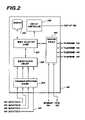
- FIG. 2further illustrates an example implementation of controller 190 .
- Controller 190receives signals from field-installed presence detectors for processing, for example via datapath 187 .
- the signalsmay include identity information which is decoded by an identification circuit 220 coupled to presence detection circuit 210 .
- a routing circuit 260is communicatively coupled to local telephone devices (e.g., telephones 122 , 142 , 162 and 182 ), as well as the Internet 194 and the local PSTN 192 .
- Routing circuit 260is arranged and configured to switch and direct calls between the various coupled circuit.
- Mode selection logic 230is coupled to identification circuit 220 , routing circuit 260 , a memory arrangement 240 , and a display controller 250 .
- Mode selection logic 230is adapted to select a telephony system operating mode responsive to detection, identity and call processing information.
- Mode selection logiccontrols display 188 through display controller 250 to display a first set of data in a first operating mode, and display a second set of data in a second operating mode.
- First and second data sets, and other operating parametersare stored in memory 240 .
Landscapes
- Engineering & Computer Science (AREA)
- Signal Processing (AREA)
- General Engineering & Computer Science (AREA)
- Telephonic Communication Services (AREA)
Abstract
Description
Claims (24)
Priority Applications (1)
| Application Number | Priority Date | Filing Date | Title |
|---|---|---|---|
| US10/041,755US7120238B1 (en) | 2001-07-12 | 2002-01-07 | Sensor-controlled telephone system |
Applications Claiming Priority (2)
| Application Number | Priority Date | Filing Date | Title |
|---|---|---|---|
| US90516101A | 2001-07-12 | 2001-07-12 | |
| US10/041,755US7120238B1 (en) | 2001-07-12 | 2002-01-07 | Sensor-controlled telephone system |
Related Parent Applications (1)
| Application Number | Title | Priority Date | Filing Date |
|---|---|---|---|
| US90516101AContinuation-In-Part | 2001-07-12 | 2001-07-12 |
Publications (1)
| Publication Number | Publication Date |
|---|---|
| US7120238B1true US7120238B1 (en) | 2006-10-10 |
Family
ID=37072482
Family Applications (1)
| Application Number | Title | Priority Date | Filing Date |
|---|---|---|---|
| US10/041,755Expired - LifetimeUS7120238B1 (en) | 2001-07-12 | 2002-01-07 | Sensor-controlled telephone system |
Country Status (1)
| Country | Link |
|---|---|
| US (1) | US7120238B1 (en) |
Cited By (36)
| Publication number | Priority date | Publication date | Assignee | Title |
|---|---|---|---|---|
| US20050233778A1 (en)* | 2004-04-16 | 2005-10-20 | Rodman Jeffrey C | Speakerphone with a cellular phone connection |
| US20050265553A1 (en)* | 2004-05-14 | 2005-12-01 | Thermond Jeffrey L | VoIP encryption bridging by home wireless router |
| US20060067340A1 (en)* | 2004-09-29 | 2006-03-30 | Johannes Ruetschi | Methods and apparatus for managing TLS connections in a large soft switch |
| US20060078101A1 (en)* | 1997-11-03 | 2006-04-13 | Light Elliott D | System and method for obtaining a status of an authorization device over a network |
| US20060193455A1 (en)* | 1997-11-03 | 2006-08-31 | Light Elliott D | System and method for establishing a call between a calling party and a called party over a wired network |
| US20070015503A1 (en)* | 2005-07-15 | 2007-01-18 | Lg Electronics Inc. | mobile terminal having an event notification function and method thereof |
| US20070071257A1 (en)* | 2003-09-30 | 2007-03-29 | Microsoft Corporation | Method and system for unified audio control on a personal computer |
| US20070154000A1 (en)* | 2005-09-21 | 2007-07-05 | Giuseppe Longobardi | Method and apparatus for forwarding incoming telecommunication calls according to receiver position |
| US20080112567A1 (en)* | 2006-11-06 | 2008-05-15 | Siegel Jeffrey M | Headset-derived real-time presence and communication systems and methods |
| WO2008082363A1 (en)* | 2007-01-05 | 2008-07-10 | Aztech Communication Pte Ltd | Internet telephony device and method of monitoring user status |
| US20080222549A1 (en)* | 2007-03-09 | 2008-09-11 | Fonality, Inc. | System and method for providing single click enterprise communication |
| US20080233969A1 (en)* | 2007-03-23 | 2008-09-25 | Federal Network Systems Llc | Call routing based on physical location of called party |
| US20090046841A1 (en)* | 2002-08-08 | 2009-02-19 | Hodge Stephen L | Telecommunication call management and monitoring system with voiceprint verification |
| US20090249391A1 (en)* | 2008-03-25 | 2009-10-01 | At&T Intellectual Property, Lp | System and Method of Delivering Event Notifications |
| US7764782B1 (en)* | 2004-03-27 | 2010-07-27 | Avaya Inc. | Method and apparatus for routing telecommunication calls |
| US20100215170A1 (en)* | 2009-02-26 | 2010-08-26 | Plantronics, Inc. | Presence Based Telephony Call Signaling |
| US7986770B2 (en) | 1997-11-03 | 2011-07-26 | Intellectual Ventures Fund 30 Llc | Method and apparatus for obtaining telephone status over a network |
| US8098810B2 (en) | 2007-03-09 | 2012-01-17 | Fonality, Inc. | Intelligent presence management in a communication routing system |
| US20130016819A1 (en)* | 2011-07-13 | 2013-01-17 | Rajesh Cheethirala | Method and structure for controlling incoming communication notification |
| US8379832B1 (en) | 2007-05-03 | 2013-02-19 | Fonality, Inc. | Universal queuing for inbound communications |
| US8483773B2 (en) | 2008-09-03 | 2013-07-09 | International Business Machines Corporation | Telephone ring extender system and method |
| US20130250034A1 (en)* | 2012-03-21 | 2013-09-26 | Lg Electronics Inc. | Mobile terminal and control method thereof |
| US8635554B2 (en) | 2003-05-20 | 2014-01-21 | Microsoft Corporation | Enhanced telephony computer user interface allowing user interaction and control of a telephone using a personal computer |
| US8719386B2 (en) | 2009-01-08 | 2014-05-06 | Fonality, Inc. | System and method for providing configuration synchronicity |
| US8780925B2 (en) | 2006-08-17 | 2014-07-15 | Fonality, Inc. | Mobile use of a PBX system |
| US9143610B2 (en) | 2002-08-08 | 2015-09-22 | Global Tel*Link Corporation | Telecommunication call management and monitoring system with voiceprint verification |
| US9215326B2 (en) | 2002-05-20 | 2015-12-15 | Callwave Communications, Llc | Systems and methods for call processing |
| US9253319B1 (en) | 2005-07-01 | 2016-02-02 | Callwave Communications, Llc | Methods and systems for call connecting calls |
| US9319523B2 (en) | 1999-04-01 | 2016-04-19 | Callwave Communications, Llc | Methods and apparatus for providing expanded telecommunications service |
| US9413885B1 (en) | 2006-10-06 | 2016-08-09 | Callwave Communications, Llc | Methods and systems for blocking unwanted communications |
| US9443244B2 (en) | 2009-03-16 | 2016-09-13 | Fonality, Inc. | System and method for utilizing customer data in a communication system |
| US9781260B2 (en) | 2013-04-29 | 2017-10-03 | Vonage Business Inc. | Detection and notification of end user presence via a telecommunications device |
| US9876900B2 (en) | 2005-01-28 | 2018-01-23 | Global Tel*Link Corporation | Digital telecommunications call management and monitoring system |
| US9924030B1 (en)* | 2002-01-02 | 2018-03-20 | 8X8, Inc. | Virtual telephone extension |
| US10097695B2 (en) | 2007-08-10 | 2018-10-09 | Fonality, Inc. | System and method for providing carrier-independent VoIP communication |
| US10318922B2 (en) | 2009-03-16 | 2019-06-11 | Fonality, Inc. | System and method for automatic insertion of call intelligence in an information system |
Citations (23)
| Publication number | Priority date | Publication date | Assignee | Title |
|---|---|---|---|---|
| US4649385A (en)* | 1982-08-13 | 1987-03-10 | Teloc R & D Ltd. | Electronic locating system for persons receiving telephone calls |
| US4658416A (en)* | 1984-02-14 | 1987-04-14 | Nec Corporation | Automatic call transfer system capable of carrying out call transfer without manual operation |
| US4932050A (en)* | 1989-06-30 | 1990-06-05 | At&T Bell Laboratories | Proximity detection for telecommunications features |
| US5019802A (en) | 1989-12-15 | 1991-05-28 | Brittain Raymond C | Intrusion detection apparatus |
| USRE33824E (en) | 1986-08-05 | 1992-02-18 | Fault detecting intrusion detection device | |
| US5189393A (en) | 1991-06-07 | 1993-02-23 | The Watt Stopper Inc. | Dual technology motion sensor |
| US5406255A (en) | 1991-10-29 | 1995-04-11 | Fujitsu Limited | Duplexed communication system |
| US5475365A (en) | 1993-01-28 | 1995-12-12 | C & K Systems, Inc. | Methods and apparatus for intrusion detection having improved immunity to false alarms |
| US5533113A (en)* | 1991-11-07 | 1996-07-02 | Fujitsu Limited | Automatic position managing system |
| US5532680A (en) | 1995-03-27 | 1996-07-02 | Ousborne; Jeffrey | Automatic message playback system |
| US5548637A (en)* | 1993-09-09 | 1996-08-20 | Precision Tracking Fm, Inc. | Method and apparatus for locating personnel and objects in response to telephone inquiries |
| US5596633A (en)* | 1993-10-12 | 1997-01-21 | Mitel Corporation | Charger/detector for cordless telephones |
| US5712911A (en)* | 1994-09-16 | 1998-01-27 | Samsung Electronics Co. Ltd. | Method and system for automatically activating and deactivating a speakerphone |
| US5781108A (en) | 1995-11-14 | 1998-07-14 | Future Tech Systems, Inc. | Automated detection and monitoring (ADAM) |
| US5822418A (en)* | 1994-02-28 | 1998-10-13 | Executone Information Systems, Inc. | Telephone communication system having a locator |
| US5923252A (en) | 1995-04-06 | 1999-07-13 | Marvel Corporation Pty Limited | Audio/visual marketing device and marketing system |
| US5982860A (en)* | 1996-03-29 | 1999-11-09 | Samsung Electronics Co., Ltd. | Facsimile system having a proximity sensor for automatically switching reception mode based upon presence or absence of an operator within a predetermined proximity zone and method for controlling the same |
| US6009333A (en)* | 1997-08-14 | 1999-12-28 | Executone Information Systems, Inc. | Telephone communication system having a locator and a scheduling facility |
| US6078253A (en) | 1997-02-04 | 2000-06-20 | Mytech Corporation | Occupancy sensor and method of operating same |
| US6211782B1 (en) | 1999-01-09 | 2001-04-03 | Heat-Timer Corporation | Electronic message delivery system utilizable in the monitoring of remote equipment and method of same |
| US6480593B1 (en)* | 1996-12-13 | 2002-11-12 | British Telecommunications Public Limited Company | Communications system automatically diverting calls when user not present |
| US6546096B1 (en)* | 1999-08-25 | 2003-04-08 | Siemens Information And Communication Networks, Inc. | Proximity detector for initiating automatic callback |
| US6842505B1 (en)* | 1999-04-05 | 2005-01-11 | Estech Systems, Inc. | Communications system enhanced with human presence sensing capabilities |
- 2002
- 2002-01-07USUS10/041,755patent/US7120238B1/ennot_activeExpired - Lifetime
Patent Citations (24)
| Publication number | Priority date | Publication date | Assignee | Title |
|---|---|---|---|---|
| US4649385A (en)* | 1982-08-13 | 1987-03-10 | Teloc R & D Ltd. | Electronic locating system for persons receiving telephone calls |
| US4658416A (en)* | 1984-02-14 | 1987-04-14 | Nec Corporation | Automatic call transfer system capable of carrying out call transfer without manual operation |
| USRE33824E (en) | 1986-08-05 | 1992-02-18 | Fault detecting intrusion detection device | |
| US4932050A (en)* | 1989-06-30 | 1990-06-05 | At&T Bell Laboratories | Proximity detection for telecommunications features |
| US5019802A (en) | 1989-12-15 | 1991-05-28 | Brittain Raymond C | Intrusion detection apparatus |
| US5189393A (en) | 1991-06-07 | 1993-02-23 | The Watt Stopper Inc. | Dual technology motion sensor |
| US5406255A (en) | 1991-10-29 | 1995-04-11 | Fujitsu Limited | Duplexed communication system |
| US5533113A (en)* | 1991-11-07 | 1996-07-02 | Fujitsu Limited | Automatic position managing system |
| US5581236A (en) | 1993-01-28 | 1996-12-03 | C & K Systems, Inc. | Methods and apparatus for intrusion detection having improved immunity to false alarms |
| US5475365A (en) | 1993-01-28 | 1995-12-12 | C & K Systems, Inc. | Methods and apparatus for intrusion detection having improved immunity to false alarms |
| US5548637A (en)* | 1993-09-09 | 1996-08-20 | Precision Tracking Fm, Inc. | Method and apparatus for locating personnel and objects in response to telephone inquiries |
| US5596633A (en)* | 1993-10-12 | 1997-01-21 | Mitel Corporation | Charger/detector for cordless telephones |
| US5822418A (en)* | 1994-02-28 | 1998-10-13 | Executone Information Systems, Inc. | Telephone communication system having a locator |
| US5712911A (en)* | 1994-09-16 | 1998-01-27 | Samsung Electronics Co. Ltd. | Method and system for automatically activating and deactivating a speakerphone |
| US5532680A (en) | 1995-03-27 | 1996-07-02 | Ousborne; Jeffrey | Automatic message playback system |
| US5923252A (en) | 1995-04-06 | 1999-07-13 | Marvel Corporation Pty Limited | Audio/visual marketing device and marketing system |
| US5781108A (en) | 1995-11-14 | 1998-07-14 | Future Tech Systems, Inc. | Automated detection and monitoring (ADAM) |
| US5982860A (en)* | 1996-03-29 | 1999-11-09 | Samsung Electronics Co., Ltd. | Facsimile system having a proximity sensor for automatically switching reception mode based upon presence or absence of an operator within a predetermined proximity zone and method for controlling the same |
| US6480593B1 (en)* | 1996-12-13 | 2002-11-12 | British Telecommunications Public Limited Company | Communications system automatically diverting calls when user not present |
| US6078253A (en) | 1997-02-04 | 2000-06-20 | Mytech Corporation | Occupancy sensor and method of operating same |
| US6009333A (en)* | 1997-08-14 | 1999-12-28 | Executone Information Systems, Inc. | Telephone communication system having a locator and a scheduling facility |
| US6211782B1 (en) | 1999-01-09 | 2001-04-03 | Heat-Timer Corporation | Electronic message delivery system utilizable in the monitoring of remote equipment and method of same |
| US6842505B1 (en)* | 1999-04-05 | 2005-01-11 | Estech Systems, Inc. | Communications system enhanced with human presence sensing capabilities |
| US6546096B1 (en)* | 1999-08-25 | 2003-04-08 | Siemens Information And Communication Networks, Inc. | Proximity detector for initiating automatic callback |
Cited By (92)
| Publication number | Priority date | Publication date | Assignee | Title |
|---|---|---|---|---|
| US7734018B2 (en)* | 1997-11-03 | 2010-06-08 | Light Elliott D | System and method for establishing a call between a calling party and a called party over a wired network |
| US20060078101A1 (en)* | 1997-11-03 | 2006-04-13 | Light Elliott D | System and method for obtaining a status of an authorization device over a network |
| US20060193455A1 (en)* | 1997-11-03 | 2006-08-31 | Light Elliott D | System and method for establishing a call between a calling party and a called party over a wired network |
| US8464359B2 (en) | 1997-11-03 | 2013-06-11 | Intellectual Ventures Fund 30, Llc | System and method for obtaining a status of an authorization device over a network |
| US7986770B2 (en) | 1997-11-03 | 2011-07-26 | Intellectual Ventures Fund 30 Llc | Method and apparatus for obtaining telephone status over a network |
| US9319523B2 (en) | 1999-04-01 | 2016-04-19 | Callwave Communications, Llc | Methods and apparatus for providing expanded telecommunications service |
| US9647978B2 (en) | 1999-04-01 | 2017-05-09 | Callwave Communications, Llc | Methods and apparatus for providing expanded telecommunications service |
| US9924030B1 (en)* | 2002-01-02 | 2018-03-20 | 8X8, Inc. | Virtual telephone extension |
| US9215326B2 (en) | 2002-05-20 | 2015-12-15 | Callwave Communications, Llc | Systems and methods for call processing |
| US9917953B2 (en) | 2002-05-20 | 2018-03-13 | Callwave Communications, Llc | Systems and methods for call processing |
| US20090046841A1 (en)* | 2002-08-08 | 2009-02-19 | Hodge Stephen L | Telecommunication call management and monitoring system with voiceprint verification |
| US9888112B1 (en) | 2002-08-08 | 2018-02-06 | Global Tel*Link Corporation | Telecommunication call management and monitoring system with voiceprint verification |
| US8948350B2 (en)* | 2002-08-08 | 2015-02-03 | Global Tel*Link Corporation | Telecommunication call management and monitoring system with voiceprint verification |
| US9143610B2 (en) | 2002-08-08 | 2015-09-22 | Global Tel*Link Corporation | Telecommunication call management and monitoring system with voiceprint verification |
| US10230838B2 (en) | 2002-08-08 | 2019-03-12 | Global Tel*Link Corporation | Telecommunication call management and monitoring system with voiceprint verification |
| US10135972B2 (en) | 2002-08-08 | 2018-11-20 | Global Tel*Link Corporation | Telecommunication call management and monitoring system with voiceprint verification |
| US9521250B2 (en) | 2002-08-08 | 2016-12-13 | Global Tel*Link Corporation | Telecommunication call management and monitoring system with voiceprint verification |
| US10091351B2 (en) | 2002-08-08 | 2018-10-02 | Global Tel*Link Corporation | Telecommunication call management and monitoring system with voiceprint verification |
| US10721351B2 (en) | 2002-08-08 | 2020-07-21 | Global Tel*Link Corporation | Telecommunication call management and monitoring system with voiceprint verification |
| US9560194B2 (en) | 2002-08-08 | 2017-01-31 | Global Tel*Link Corp. | Telecommunication call management and monitoring system with voiceprint verification |
| US10069967B2 (en) | 2002-08-08 | 2018-09-04 | Global Tel*Link Corporation | Telecommunication call management and monitoring system with voiceprint verification |
| US9686402B2 (en) | 2002-08-08 | 2017-06-20 | Global Tel*Link Corp. | Telecommunication call management and monitoring system with voiceprint verification |
| US10944861B2 (en) | 2002-08-08 | 2021-03-09 | Global Tel*Link Corporation | Telecommunication call management and monitoring system with voiceprint verification |
| US9930172B2 (en) | 2002-08-08 | 2018-03-27 | Global Tel*Link Corporation | Telecommunication call management and monitoring system using wearable device with radio frequency identification (RFID) |
| US11496621B2 (en) | 2002-08-08 | 2022-11-08 | Global Tel*Link Corporation | Telecommunication call management and monitoring system with voiceprint verification |
| US9699303B2 (en) | 2002-08-08 | 2017-07-04 | Global Tel*Link Corporation | Telecommunication call management and monitoring system with voiceprint verification |
| US9392043B2 (en) | 2003-05-20 | 2016-07-12 | Microsoft Technology Licensing, Llc | Enhanced telephony computer user interface allowing user interaction and control of a telephone using a personal computer |
| US8635554B2 (en) | 2003-05-20 | 2014-01-21 | Microsoft Corporation | Enhanced telephony computer user interface allowing user interaction and control of a telephone using a personal computer |
| US8694915B2 (en) | 2003-05-20 | 2014-04-08 | Microsoft Corporation | Enhanced telephony computer user interface allowing user interaction and control of a telephone using a personal computer |
| US20100008488A1 (en)* | 2003-09-30 | 2010-01-14 | Microsoft Corporation | Method and system for unified audio control on a personal computer |
| US8443179B2 (en) | 2003-09-30 | 2013-05-14 | Microsoft Corporation | Method and system for unified audio control on a personal computer |
| US20070071257A1 (en)* | 2003-09-30 | 2007-03-29 | Microsoft Corporation | Method and system for unified audio control on a personal computer |
| US8245027B2 (en) | 2003-09-30 | 2012-08-14 | Microsoft Corporation | Method and system for unified audio control on a personal computer |
| US8644481B2 (en)* | 2003-09-30 | 2014-02-04 | Microsoft Corporation | Method and system for unified audio control on a personal computer |
| US7764782B1 (en)* | 2004-03-27 | 2010-07-27 | Avaya Inc. | Method and apparatus for routing telecommunication calls |
| US20050233778A1 (en)* | 2004-04-16 | 2005-10-20 | Rodman Jeffrey C | Speakerphone with a cellular phone connection |
| US7529566B2 (en)* | 2004-04-16 | 2009-05-05 | Polycom, Inc. | Speakerphone with a cellular phone connection |
| US8619989B2 (en)* | 2004-05-14 | 2013-12-31 | Broadcom Corporation | VolP encryption bridging by home wireless router |
| US20050265553A1 (en)* | 2004-05-14 | 2005-12-01 | Thermond Jeffrey L | VoIP encryption bridging by home wireless router |
| US7570163B2 (en)* | 2004-09-29 | 2009-08-04 | Siemens Communications, Inc. | Methods and apparatus for managing TLS connections in a large soft switch |
| US20060067340A1 (en)* | 2004-09-29 | 2006-03-30 | Johannes Ruetschi | Methods and apparatus for managing TLS connections in a large soft switch |
| US9876900B2 (en) | 2005-01-28 | 2018-01-23 | Global Tel*Link Corporation | Digital telecommunications call management and monitoring system |
| US9253319B1 (en) | 2005-07-01 | 2016-02-02 | Callwave Communications, Llc | Methods and systems for call connecting calls |
| US20070015503A1 (en)* | 2005-07-15 | 2007-01-18 | Lg Electronics Inc. | mobile terminal having an event notification function and method thereof |
| US7853291B2 (en)* | 2005-07-15 | 2010-12-14 | Lg Electronics Inc. | Mobile terminal having an event notification function and method thereof |
| US20070154000A1 (en)* | 2005-09-21 | 2007-07-05 | Giuseppe Longobardi | Method and apparatus for forwarding incoming telecommunication calls according to receiver position |
| US8306207B2 (en)* | 2005-09-21 | 2012-11-06 | International Business Machines Corporation | Method and apparatus for forwarding incoming telecommunication calls according to receiver position |
| US8780925B2 (en) | 2006-08-17 | 2014-07-15 | Fonality, Inc. | Mobile use of a PBX system |
| US9692891B1 (en) | 2006-10-06 | 2017-06-27 | Callwave Communications, Llc | Methods and systems for blocking unwanted communications |
| US9413885B1 (en) | 2006-10-06 | 2016-08-09 | Callwave Communications, Llc | Methods and systems for blocking unwanted communications |
| US9591392B2 (en) | 2006-11-06 | 2017-03-07 | Plantronics, Inc. | Headset-derived real-time presence and communication systems and methods |
| US20080112567A1 (en)* | 2006-11-06 | 2008-05-15 | Siegel Jeffrey M | Headset-derived real-time presence and communication systems and methods |
| WO2008082363A1 (en)* | 2007-01-05 | 2008-07-10 | Aztech Communication Pte Ltd | Internet telephony device and method of monitoring user status |
| US20100046505A1 (en)* | 2007-01-05 | 2010-02-25 | Jason Saw | Internet Telephony Device and Method of Monitoring User Status |
| US8976952B2 (en) | 2007-03-09 | 2015-03-10 | Fonality, Inc. | Intelligent presence management in a communication routing system |
| US20080222549A1 (en)* | 2007-03-09 | 2008-09-11 | Fonality, Inc. | System and method for providing single click enterprise communication |
| US8693659B2 (en) | 2007-03-09 | 2014-04-08 | Fonality, Inc. | System and method for centralized presence management of local and remote users |
| US8495653B2 (en) | 2007-03-09 | 2013-07-23 | Fonality, Inc. | System and method for event driven browser launch |
| US8098810B2 (en) | 2007-03-09 | 2012-01-17 | Fonality, Inc. | Intelligent presence management in a communication routing system |
| US9395873B2 (en) | 2007-03-09 | 2016-07-19 | Fonality, Inc. | System and method for providing single click enterprise communication |
| US8787548B2 (en) | 2007-03-09 | 2014-07-22 | Fonality, Inc. | System and method for distributed communication control within an enterprise |
| US8341535B2 (en) | 2007-03-09 | 2012-12-25 | Fonality, Inc. | System and method for distributed communication control within an enterprise |
| US8499246B2 (en) | 2007-03-09 | 2013-07-30 | Fonality, Inc. | System and method for providing single click enterprise communication |
| US8832717B2 (en) | 2007-03-09 | 2014-09-09 | Fonality, Inc. | System and method for event driven browser launch |
| US20080233969A1 (en)* | 2007-03-23 | 2008-09-25 | Federal Network Systems Llc | Call routing based on physical location of called party |
| US8116441B2 (en)* | 2007-03-23 | 2012-02-14 | Verizon Patent And Licensing Inc. | Call routing based on physical location of called party |
| US8379832B1 (en) | 2007-05-03 | 2013-02-19 | Fonality, Inc. | Universal queuing for inbound communications |
| US8571202B2 (en) | 2007-05-03 | 2013-10-29 | Fonality, Inc. | Universal queuing for inbound communications |
| US9001993B2 (en) | 2007-05-03 | 2015-04-07 | Fonality, Inc. | Universal queuing for inbound communications |
| US11595529B2 (en) | 2007-08-10 | 2023-02-28 | Sangoma Us Inc. | System and method for providing carrier-independent VoIP communication |
| US10771632B2 (en) | 2007-08-10 | 2020-09-08 | Fonality, Inc. | System and method for providing carrier-independent VoIP communication |
| US10097695B2 (en) | 2007-08-10 | 2018-10-09 | Fonality, Inc. | System and method for providing carrier-independent VoIP communication |
| US8234676B2 (en)* | 2008-03-25 | 2012-07-31 | At&T Intellectual Property I, Lp | System and method of delivering event notifications |
| US20090249391A1 (en)* | 2008-03-25 | 2009-10-01 | At&T Intellectual Property, Lp | System and Method of Delivering Event Notifications |
| US8621524B2 (en) | 2008-03-25 | 2013-12-31 | At&T Intellectual Property I, Lp | System and method of delivering event notifications |
| US8483773B2 (en) | 2008-09-03 | 2013-07-09 | International Business Machines Corporation | Telephone ring extender system and method |
| US8719386B2 (en) | 2009-01-08 | 2014-05-06 | Fonality, Inc. | System and method for providing configuration synchronicity |
| US8428053B2 (en) | 2009-02-26 | 2013-04-23 | Plantronics, Inc. | Presence based telephony call signaling |
| US8798042B2 (en) | 2009-02-26 | 2014-08-05 | Plantronics, Inc. | Presence based telephony call signaling |
| US20100215170A1 (en)* | 2009-02-26 | 2010-08-26 | Plantronics, Inc. | Presence Based Telephony Call Signaling |
| US10834254B2 (en) | 2009-03-16 | 2020-11-10 | Fonality, Inc. | System and method for utilizing customer data in a communication system |
| US10318922B2 (en) | 2009-03-16 | 2019-06-11 | Fonality, Inc. | System and method for automatic insertion of call intelligence in an information system |
| US9955004B2 (en) | 2009-03-16 | 2018-04-24 | Fonality, Inc. | System and method for utilizing customer data in a communication system |
| US11113663B2 (en) | 2009-03-16 | 2021-09-07 | Fonality, Inc. | System and method for automatic insertion of call intelligence in an information system |
| US11223720B2 (en) | 2009-03-16 | 2022-01-11 | Fonality, Inc. | System and method for utilizing customer data in a communication system |
| US11501254B2 (en) | 2009-03-16 | 2022-11-15 | Sangoma Us Inc. | System and method for automatic insertion of call intelligence in an information system |
| US9443244B2 (en) | 2009-03-16 | 2016-09-13 | Fonality, Inc. | System and method for utilizing customer data in a communication system |
| US8660248B2 (en)* | 2011-07-13 | 2014-02-25 | Rajesh Cheethirala | Method and structure for controlling incoming communication notification |
| US20130016819A1 (en)* | 2011-07-13 | 2013-01-17 | Rajesh Cheethirala | Method and structure for controlling incoming communication notification |
| US20130250034A1 (en)* | 2012-03-21 | 2013-09-26 | Lg Electronics Inc. | Mobile terminal and control method thereof |
| US8928723B2 (en)* | 2012-03-21 | 2015-01-06 | Lg Electronics Inc. | Mobile terminal and control method thereof |
| US9781260B2 (en) | 2013-04-29 | 2017-10-03 | Vonage Business Inc. | Detection and notification of end user presence via a telecommunications device |
Similar Documents
| Publication | Publication Date | Title |
|---|---|---|
| US7120238B1 (en) | Sensor-controlled telephone system | |
| US6298122B1 (en) | Caller ID system | |
| US8705701B2 (en) | Security system with call management functionality | |
| EP1465131B1 (en) | Integrated security and communications system with secure communications link | |
| US6263071B1 (en) | Telecommunications functions management system providing distinctive alerting based on caller selected option | |
| US6434394B1 (en) | Multiple handset cordless telephone including a ring signal/call routing module | |
| US6697473B2 (en) | Automated personalized telephone management system | |
| US7263181B2 (en) | Telephony system and a method of operating same | |
| US5943414A (en) | Transparent protected access to corporate dialing plan | |
| US8464359B2 (en) | System and method for obtaining a status of an authorization device over a network | |
| US5457731A (en) | Emergency telecommunications device for the disabled | |
| CN1132343C (en) | Radio-telephone system | |
| US7499527B2 (en) | System and method for determining the status of a telephone in a packet switched network | |
| KR200199110Y1 (en) | Auto attendant system | |
| JPH09238178A (en) | Telephone equipment | |
| JPH09130486A (en) | Ringing control method having provision for caller subscriber | |
| HK1088481B (en) | A telephony system and a method of operating same | |
| JP2000059830A (en) | Private branch exchange | |
| JPH1168928A (en) | Automatic answering telephone equipment and its call incoming answering method | |
| HK1026535A (en) | Cordless telephone system | |
| KR20040012240A (en) | Interphone/External Telephone Automatic Connection System | |
| JP2000069124A (en) | Call termination notification method in telephone set with caller number display function | |
| AU9468498A (en) | Method and device in telecommunications system | |
| KR20030037367A (en) | Telephone connection apparatus and auto connection method for company network | |
| JPH0851485A (en) | Telephone transfer method using LAN |
Legal Events
| Date | Code | Title | Description |
|---|---|---|---|
| AS | Assignment | Owner name:8X8, INC., CALIFORNIA Free format text:ASSIGNMENT OF ASSIGNORS INTEREST;ASSIGNORS:BEDNARZ, PHILIPS;BARRETT, JOHN L.;REEL/FRAME:012843/0197;SIGNING DATES FROM 20020321 TO 20020322 | |
| STCF | Information on status: patent grant | Free format text:PATENTED CASE | |
| FPAY | Fee payment | Year of fee payment:4 | |
| FPAY | Fee payment | Year of fee payment:8 | |
| MAFP | Maintenance fee payment | Free format text:PAYMENT OF MAINTENANCE FEE, 12TH YEAR, LARGE ENTITY (ORIGINAL EVENT CODE: M1553) Year of fee payment:12 | |
| AS | Assignment | Owner name:WILMINGTON SAVINGS FUND SOCIETY, FSB, DELAWARE Free format text:INTELLECTUAL PROPERTY SECURITY AGREEMENT;ASSIGNORS:8X8, INC.;FUZE, INC.;REEL/FRAME:061085/0861 Effective date:20220803 | |
| AS | Assignment | Owner name:WILMINGTON SAVINGS FUND SOCIETY, FSB, DELAWARE Free format text:CORRECTIVE ASSIGNMENT TO CORRECT THE PROPERTY NUMBERS SECTION TO REMOVE APPLICATION NUMBERS 11265423, 11252205, 11240370, 11252276, AND 11297182 PREVIOUSLY RECORDED ON REEL 061085 FRAME 0861. ASSIGNOR(S) HEREBY CONFIRMS THE INTELLECTUAL PROPERTY SECURITY AGREEMENT;ASSIGNORS:8X8, INC.;FUZE, INC.;REEL/FRAME:066383/0936 Effective date:20220803 | |
| AS | Assignment | Owner name:FUZE, INC., MASSACHUSETTS Free format text:RELEASE BY SECURED PARTY;ASSIGNOR:WILMINGTON SAVINGS FUND SOCIETY, FSB;REEL/FRAME:068328/0569 Effective date:20240805 Owner name:8X8, INC., CALIFORNIA Free format text:RELEASE BY SECURED PARTY;ASSIGNOR:WILMINGTON SAVINGS FUND SOCIETY, FSB;REEL/FRAME:068328/0569 Effective date:20240805 |