US7119890B2 - System and method for illuminating a platen in a live scanner and producing high-contrast print images - Google Patents
System and method for illuminating a platen in a live scanner and producing high-contrast print imagesDownload PDFInfo
- Publication number
- US7119890B2 US7119890B2US11/246,525US24652505AUS7119890B2US 7119890 B2US7119890 B2US 7119890B2US 24652505 AUS24652505 AUS 24652505AUS 7119890 B2US7119890 B2US 7119890B2
- Authority
- US
- United States
- Prior art keywords
- prism
- illumination
- light
- rays
- platen
- Prior art date
- Legal status (The legal status is an assumption and is not a legal conclusion. Google has not performed a legal analysis and makes no representation as to the accuracy of the status listed.)
- Expired - Lifetime
Links
Images


Classifications
- G—PHYSICS
- G06—COMPUTING OR CALCULATING; COUNTING
- G06V—IMAGE OR VIDEO RECOGNITION OR UNDERSTANDING
- G06V40/00—Recognition of biometric, human-related or animal-related patterns in image or video data
- G06V40/10—Human or animal bodies, e.g. vehicle occupants or pedestrians; Body parts, e.g. hands
- G06V40/12—Fingerprints or palmprints
- G06V40/13—Sensors therefor
- G06V40/1324—Sensors therefor by using geometrical optics, e.g. using prisms
Definitions
- the present inventionpertains to biometric imaging technology, and in particular, to live scanning of ridge print patterns.
- Biometric imaging systemsinclude, but are not limited to, print ridge pattern or print imaging systems. These print imaging systems are often referred to in the relevant art as scanners or live scanners.
- Conventional live scannersuse light to detect an image of a print. For example, an object having a print such as one or more fingers can be placed on a platen of a live scanner. An illumination source illuminates the underside of the platen. An image representative of the ridge pattern of the print is detected by an image sensor such as, for example, a solid-state camera.
- Live scannersare desired that can capture print images having a high-contrast and a high-resolution.
- One standard for live scanners promulgated by the Federal Bureau of Investigation (FBI)is the Integrated Automated Fingerprint Identification System (IAFIS) Image Quality Specifications (IQS) (Appendix F).
- IAFISIntegrated Automated Fingerprint Identification System
- IQSImage Quality Specifications
- conventional live scannershave illumination systems that directly illuminate the underside of a platen. As described below, this direct illumination of the underside of the platen has drawbacks.
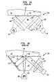
- FIG. 1Aillustrates a first conventional live scanner 100 having an optical axis (OA) 101 .
- Live scanner 100includes an illumination source 102 , an illumination optic system 104 , a prism 106 , a camera optical system 108 , and a camera 110 .
- prism 106includes three surfaces 120 , 122 and 124 .
- Surface 120is the platen (platen 120 ).
- rays of light emitted from illumination source 102directly illuminate platen 120 .
- an object having a print ridge patternsuch as, for example, finger 112 is placed on platen 120 of live scanner 100 for imaging.
- Illumination source 102 of live scanner 100emits rays of light. These rays of light are gathered by illumination optic system 104 and directed toward surface 122 of prism 106 .
- TIRtotal internal reflection
- Rays of light hitting portions of platen 120 corresponding to valleys 114 of finger 112are totally internally reflected toward surface 124 of prism 106 . These totally internally reflected rays of light exit prism 106 at surface 124 .
- Camera optics system 108collects the rays of light exiting prism 106 at surface 124 and focuses them on an imaging portion of camera 110 .
- Camera 110forms an image of the print ridge pattern of finger 112 using the totally internally reflected rays of light.
- dark linescorrespond to ridges 114 of finger 112 while light lines correspond to valleys 116 of finger 112 .
- a complex illumination systemis often used, which can make live scanner 100 cost prohibitive.
- FIG. 1Billustrates a second conventional live scanner 150 .
- Live scanner 150includes an illumination source 102 , a prism 152 , a camera optic system 108 , and a camera 110 .
- prism 152includes four surfaces 154 , 156 , 158 , and 160 .
- Surface 154is the platen (platen 154 ).
- a black coating of paint 170is applied to surface 158 .
- rays of light emitted from illumination source 102directly illuminate the underside of platen 154 .
- an object having a print ridge patternsuch as, for example, finger 112 is placed on platen 154 of live scanner 150 for imaging.
- Illumination source 102 of live scanner 150emits rays of light that enter prism 152 through surface 156 . These rays of light directly illuminate the underside of platen 154 . A portion of these direct rays of light are diffused and scattered by print ridges 114 of finger 112 . These diffused and scattered rays of light are used to form a print image. Any direct rays of light from illumination source 102 that do not hit a ridge 114 of finger 112 exit prism 150 at platen 154 because these rays of light are not in TIR. Rays of light exiting prism 150 at platen 154 (e.g., because of the presence of a valley 116 of finger 112 ) cannot be used to form the print image.
- light linescorrespond to print ridges while dark lines correspond to print valleys.
- the reflected rays of light that help form the print imagehave a lower intensity than the rays of light that travel directly from ridges 114 toward camera optics system 108 and camera 110 without being reflected.
- This difference in intensityprovides image contrast, i.e., a contrast between print ridges and print valleys.
- the direct rays of lighthave a higher intensity that the reflected rays of light and thus form the light lines that correspond to print ridges.
- the lower intensity reflected rays of lightform dark lines that correspond to print valleys.
- live scanner 150relies on print ridges to diffuse and scatter light used for print image formation, live scanner 150 cannot be used to form high-contrast print images for certain individuals having dark print ridges (i.e., print ridges that contain more than some threshold amount of the skin pigment melanin, particularly the form know as eumelanin). Dark print ridges absorb more light than lighter print ridges. Thus, as a result, dark print ridges diffuse and scatter less light than lighter print ridges, resulting in the formation of lower contrast images.
- a live scannerthat does not have the shortcomings of a conventional live scanner.
- a live scannerwithout a complex illumination system that can produce a high-contrast print image for any individual.
- the present inventionprovides systems and methods for illuminating a platen in a live scanner and producing high-contrast print images.
- light from an illumination sourceis injected into a prism of a print scanner through an illumination injection surface.
- the illumination injection surfaceis a surface that is not directly imaged by an optical system and an image sensor of the print scanner.
- This injected lighttravels within the prism and hits a reflective surface of the prism at an angle that is less than the critical angle of the reflective surface. When this light hits the reflective surface, it is scattered and becomes diffused. Some rays of this diffused light remain in total internal reflection (TIR) within the prism, are reflected from the underside of the platen surface of the prism, and travel along an optical axis of an optical system for detection at an image sensor.
- TIRtotal internal reflection
- the illumination injection surfaceis a flat surface connecting the platen to an image viewing surface.
- the angle formed between the platen and the illumination injection surfaceis at least ninety degrees.
- An optional lensmay be placed between the illumination injection surface and an illumination source used to inject light into the prism.
- the illumination injection surfaceis a curved surface connecting the platen to the image viewing surface.
- the illumination injection surfaceis a portion of the platen.
- the illumination reflection surface of the prismis coated with a reflective coating that efficiently diffuses incident light.
- this reflective coatingis paint such as, for example, reflective white paint.
- the illumination reflection surface of the prismis ground, roughened and/or frosted prior to having the reflective coating applied.
- illumination sources and camerascan be used. These different illumination sources and cameras can be used alone or in combination with optical lenses.
- FIG. 1Ais a cross-sectional schematic diagram of an optical system of a first conventional live scanner.
- FIG. 1Bis a cross-sectional schematic diagram of an optical system of a second conventional live scanner.
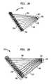
- FIG. 2Ais a cross-sectional schematic diagram of an optical system of a live scanner according to the present invention.
- FIG. 2Bis a cross-sectional schematic diagram of a second optical system of a live scanner according to the present invention.
- FIG. 3Ais a cross-sectional schematic diagram of the illumination source and the prism of FIG. 2A .
- FIG. 3Bis a cross-sectional schematic diagram of another example embodiment of an illumination source and a prism according to the present invention.
- FIG. 4is a cross-sectional schematic diagram illustrating the total internal reflection (TIR) operation of the live scanner of FIG. 2A .
- FIG. 5is a cross-sectional schematic diagram illustrating how the presence of a finger changes the TIR operation of the live scanner of FIG. 2A .
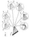
- FIG. 6is a cross-sectional schematic diagram illustrating various illumination injection surfaces according to the present invention.
- FIG. 7is a flowchart illustrating the steps of a method for producing a ridge pattern image with a live scanner according to the present invention.
- the present inventionprovides among other things a simplified means for achieving uniform, diffuse light illumination of a platen in a live scanner.
- Live scanners incorporating the present inventionare able to meet the increasing demands for capturing high-resolution and high-contrast print images.
- fingerrefers to any digit on a hand including, but not limited to, a thumb, an index finger, a middle finger, a ring finger, or a pinky finger.
- live scanrefers to a scan of any print ridge pattern made by a print scanner.
- a live scancan include, but is not limited to, a scan of a finger, a finger roll, a flat finger, a slap print of four fingers, a thumb print, a palm print, or a combination of fingers, such as, sets of fingers and/or thumbs from one or more hands or one or more palms disposed on a platen.
- a flat printconsists of a fingerprint image of a digit (finger or thumb) pressed flat against the platen.
- a roll printconsists of an image of a digit (finger or thumb) made while the digit (finger or thumb) is rolled from one side of the digit to another side of the digit over the surface of the platen.
- a slap printconsists of an image of four flat fingers pressed flat against the platen.
- a palm printinvolves pressing all or part of a palm upon the platen.
- a platencan be movable or stationary depending upon the particular type of scanner and the type of print being captured by the scanner.
- biometric imaging system“print scanner,” “scanner,” “live scanner,” “live print scanner,” and “fingerprint scanner” are used interchangeably, and refer to any type of scanner which can obtain an image of a print ridge pattern in a live scan.
- the obtained imagescan be combined in any format including, but not limited to, an FBI, state, or international tenprint format.
- platenrefers to a component that includes an imaging surface upon which at least one finger, for example, is placed during a live scan.
- a platencan include, but is not limited to, a surface of an optical prism or a surface of a silicone layer or other element disposed in optical contact with a surface of an optical prism.
- FIG. 2Ais a cross-sectional schematic diagram of a live scanner 200 according to the present invention.
- Live scanner 200includes a prism 201 , an illumination source 206 , an image sensor 208 , and an optical system 210 .
- Surface 202 of prism 201is the platen surface or platen.
- Surface 204 of prism 201is a highly reflective surface referred to herein as an illumination reflection surface.
- surface 204is ground or frosted to reduce specular reflection and coated with highly reflective white paint to produce efficient diffused reflection.
- the inventionis not limited, however, to using only white paint. Colors other than white can be used and may be preferable to white depending on the wavelengths of light emitted by the illumination source 206 that is used.
- the reflective surface 204 or reflective coating applied to surface 204is a holographic film that concentrates the reflected light in such a way that it enhances the amount of light hitting the underside of the platen at angles greater than the total internal reflection critical angle, thereby improving illumination efficiency and image contrast.
- optical system 210includes three lenses 212 , 214 , and 216 , and an aperture 218 to focus light from prism 201 onto image sensor 208 .
- Illumination source 206can be any illumination source such as, for example, an array of light-emitting diodes (LEDs).
- Image sensor 208can be any type of image sensor such as, for example, a solid state camera.
- Live scanner 200operates as follows. Light from illumination source 206 is injected into prism 201 through an illumination injection surface 203 that is not directly imaged by optical system 210 and image sensor 208 . This light travels internally through prism 201 and hits the highly reflective surface or illumination reflection surface 204 of prism 201 . When this light hits surface 204 , it is scattered and becomes diffused. Some of this diffused light remains in total internal reflection (TIR) and is reflected off the underside of platen surface 201 . The TIR reflected light exits prism 201 at an image viewing surface 205 and is imaged by optical system 210 and image sensor 208 . Optical rays 209 illustrate the imaging field of optical system 210 and image sensor 208 .
- TIRtotal internal reflection
- live scanner 200The operation of live scanner 200 is further described below with reference to FIGS. 3–5 .
- FIG. 2Bis a cross-sectional schematic diagram of a live scanner 250 according to the present invention.
- Live scanner 250includes a prism 251 , an illumination source 254 , a camera 256 , and an optical system 258 .
- Surface 252 of prism 251is the platen surface or platen.
- Surface 254 of prism 251is a highly reflective surface or illumination reflection surface. In a preferred embodiment, surface 254 is ground or frosted to reduce specular reflection and coated with highly reflective white paint 260 to produce efficient diffused reflection.
- live scanner 250is not limited to using only white paint. Colors other than white can be used and may be preferable to white depending on the wavelengths of light emitted by the illumination source 254 that is used.
- Surface 262 of prism 251is the illumination injection surface.
- Surface 264 of prism 251is the image viewing surface.
- Live scanner 250operates in a manner similar to live scanner 200 .
- FIG. 3Ais a cross-sectional schematic diagram of illumination source 206 and prism 201 of FIG. 2A .
- light rays 302enter prism 201 from illumination source 206 at illumination injection surface 203 .
- the light rays 302travel internally through prism 201 and hit surface 204 of prism 201 .
- Surface 204scatters and diffuses light rays 302 to produce diffused light 304 .
- illumination injection surface 203connects platen surface 202 to image viewing surface 205 .
- the internal angle of prism 201 formed between platen surface 202 and illumination injection surface 203is greater than ninety degrees. Using an internal angle of greater than ninety degrees between platen surface 202 and illumination injection surface 203 limits the number of light rays 302 that enter illumination injection surface 203 from illumination source 206 and hit the underside of platen surface 202 before being diffused by illumination reflection surface 204 . In certain embodiments, limiting the number of light rays 302 from illumination source 206 that hit the underside of platen surface 202 before being diffused by illumination reflection surface 204 can improve the contrast of a print image formed by image sensor 208 .
- FIG. 3Bis a cross-sectional schematic diagram of illumination source 206 and a prism 310 .
- light rays 302enter prism 310 from illumination source 206 at illumination injection surface 313 .
- the light rays 302travel internally through prism 310 and hit surface 315 of prism 310 .
- Surface 315scatters and diffuses light rays 302 to produce diffused light 304 .
- illumination injection surface 313connects platen surface 314 to image viewing surface 317 .
- Illumination injection surface 313is perpendicular to platen surface 314 .
- rays of light emitted by illumination source 206are shown entering prism 310 and traveling internally through prism 313 .
- a number of these light rays 302travel directly across prism 310 until they reach surface 315 .
- Some of these light rays 302are reflected off the underside of platen surface 314 and are redirected towards, for example, area 320 of surface 315 .
- These redirected light rays 302are beneficial certain embodiments and are used to redistribute the rays of light from illumination source 206 in such a way as to minimize differences in illumination intensity across surface 315 .
- FIG. 4is a cross-sectional schematic diagram illustrating the TIR operation of live scanner 200 of FIG. 2A .
- some of the diffused light 304 formed by surface 204hits platen 202 and remains in TIR. This diffused light is reflected off the underside of platen surface 202 . Rays of light totally internally reflected off platen surface 202 exit prism 201 at image viewing surface 205 and are imaged by optical system 210 and image sensor 208 .
- Diffused light rays 401 , 402 , and 403illustrate the imaging field of optical system 210 and image sensor 208 .
- FIG. 5is a cross-sectional schematic diagram illustrating how the presence of a finger 502 changes the TIR operation of live scanner 200 of FIG. 2A .
- the fingerprint ridges of finger 502break the TIR of platen surface 202 .
- the diffused lightescapes prism 201 at the places where the TIR at platen surface 202 is broken.
- diffused light rays 401 and 403are imaged by optical system 210 and image sensor 208 despite the presence of finger 502 .
- diffused light ray 402hits a portion of platen surface 202 where the TIR of platen surface 202 is broken by the presence of a fingerprint ridge.
- light ray 402escapes prism 201 at platen surface 202 and is not collected by optical system 210 .
- the fingerprint ridge pattern image formed by image sensor 208the fingerprint ridges of finger 502 appear dark and the fingerprint valleys of finger 502 appear light.
- FIG. 6is a cross-sectional schematic diagram illustrating various illumination injection surfaces according to the present invention. As described herein, these various embodiments allow a print scanner according to the present invention to achieve a flat, diffused illumination of the underside of a platen surface of a prism such as, for example, prism 201 . Each of the embodiments illustrated in FIG. 6 operates in a manner similar to that described herein for live scanner 200 .
- Embodiment 602 in FIG. 6is the embodiment of the present invention described above with regard to FIG. 3A .
- Embodiment 602comprises prism 201 and illumination source 206 .
- illumination injection surface 203is a flat surface that connects platen surface 202 and image viewing surface 205 .
- the angle formed between platen surface 202 and image viewing surface 205is greater than ninety degrees.
- no lenseis used between illumination source 206 and illumination injection surface 203 .
- Embodiment 604is similar to embodiment 602 except that it includes a lens 605 positioned between prism 201 and illumination source 206 .
- Lense 605is a conventional optical lens used, for example, to shape and/or to filter the light emitted from illumination source 206 . Shaping and/or filtering the light emitted by illumination source 206 before it is injected into prism 201 is beneficial for reasons that will be known to persons skilled in the relevant arts given the description herein.
- Embodiment 606is also similar to embodiment 602 except that it includes a lens 607 positioned between prism 201 and illumination source 206 .
- Lense 607is a diffusing lens that diffuses the light emitted from illumination source 206 before it is injected into prism 201 . As would be known to persons skilled in the relevant arts, it is beneficial to use a diffusing lense with certain illumination sources.
- Embodiment 608illustrates prism 201 having a curved illumination injection surface 609 .
- the curvature of illumination injection surface 609bends incident light.
- prism 201 with curved injection illumination surface 609it is possible, for example, to use a physically smaller illumination source 611 to inject light into prism 201 .
- the shape of curved illumination injection surface 609is illustrative and not intended to limit the present invention.
- Embodiment 610is the embodiment of the present invention described above with regard to FIG. 3B .
- Illumination injection surface 613is flat and perpendicular to platen surface 202 .
- rays of light emitted by illumination source 206enter prism 201 and travel internally through prism 201 . Many of these rays of light travel directly across prism 201 until they reach the reflective surface (not shown). Some of these rays of light, however, are reflected off the underside of surface 202 and are redirected towards the reflective surface (not shown). These redirected rays of light are beneficial in certain embodiments and are used to redistribute the light from illumination source 206 in such a way as to minimize differences in illumination intensity across the reflective surface.
- Embodiment 612is similar to embodiment 610 except that illumination source 206 has been repositioned so that it injects light into prism 201 through an end portion of platen surface 202 .
- Embodiment 612illustrates an example of the present invention wherein a single surface of prism 201 serves as both the platen surface and the illumination injection surface.
- An advantage of embodiment 612is that it is more compact than embodiment 610 since illumination source 206 is now adjacent to platen surface 202 rather than surface 613 .
- FIG. 6is illustrative and not intended to limit the present invention.
- FIG. 7illustrates a flowchart of the steps of a method 700 according to the present invention for producing a pattern image such as, for example, a ridge print pattern of a fingerprint, palm print, and/or footprint. As shown in FIG. 7 , method 700 comprises five steps.
- Method 700will now be described with reference to a live scanner having a prism, an illumination source, an optical system, and an image sensor. This structure is intended to aid in the description of method 700 , and it is not intended to limit the invention.
- step 702light is injected into the prism of the live scanner.
- the lightis preferably injected through an illumination injection surface of the prism that is not imaged by the image sensor of the live scanner.
- FIG. 6illustrates various exemplary arrangements of an illumination source and a prism that can be used to inject light into a prism. Once injected, the injected light travels internally through the prism until it hits an illumination reflection surface of the prism.
- the injected lightis diffused by the illumination reflection surface of the prism.
- the illumination reflection surface of the prismshould have a coating such as a reflective paint that efficiently diffuses incident light.
- the illumination reflection surfacecan also be ground, frosted, or otherwise conditioned prior to coating to reduce spectral reflections.
- a platen surface of the prismis illuminated with the diffused light reflected off the illumination reflection surface of the prism. At least some of the reflected, diffused light remains in TIR in the prism and is reflected off the underside of the platen surface of the prism. As noted above, the presence of a finger ridge or a palm ridge on the platen surface will break the TIR of the platen surface.
- step 708light reflected off the platen surface of the prism is collected.
- the purpose of this collection stepis to ensure that sufficient light from the platen surface, which is representative of a ridge pattern, is appropriately directed to an image sensor.
- This collection stepis performed by the optical system of the live scanner.
- step 710the light collected in step 708 is focused onto an imaging portion of an image sensor, where it can be used to form an image of a ridge print pattern present on the platen surface of the prism.
Landscapes
- Engineering & Computer Science (AREA)
- Physics & Mathematics (AREA)
- Theoretical Computer Science (AREA)
- Human Computer Interaction (AREA)
- General Physics & Mathematics (AREA)
- Multimedia (AREA)
- Optics & Photonics (AREA)
- Image Input (AREA)
- Facsimile Scanning Arrangements (AREA)
- Investigating Or Analysing Materials By Optical Means (AREA)
- Measurement Of The Respiration, Hearing Ability, Form, And Blood Characteristics Of Living Organisms (AREA)
- Light Sources And Details Of Projection-Printing Devices (AREA)
- Projection-Type Copiers In General (AREA)
Abstract
Description
Claims (15)
Priority Applications (1)
| Application Number | Priority Date | Filing Date | Title |
|---|---|---|---|
| US11/246,525US7119890B2 (en) | 2003-06-17 | 2005-10-11 | System and method for illuminating a platen in a live scanner and producing high-contrast print images |
Applications Claiming Priority (2)
| Application Number | Priority Date | Filing Date | Title |
|---|---|---|---|
| US10/462,592US6954261B2 (en) | 2003-06-17 | 2003-06-17 | System and method for illuminating a platen in a live scanner and producing high-contrast print images |
| US11/246,525US7119890B2 (en) | 2003-06-17 | 2005-10-11 | System and method for illuminating a platen in a live scanner and producing high-contrast print images |
Related Parent Applications (1)
| Application Number | Title | Priority Date | Filing Date |
|---|---|---|---|
| US10/462,592ContinuationUS6954261B2 (en) | 2003-06-17 | 2003-06-17 | System and method for illuminating a platen in a live scanner and producing high-contrast print images |
Publications (2)
| Publication Number | Publication Date |
|---|---|
| US20060028635A1 US20060028635A1 (en) | 2006-02-09 |
| US7119890B2true US7119890B2 (en) | 2006-10-10 |
Family
ID=33516951
Family Applications (2)
| Application Number | Title | Priority Date | Filing Date |
|---|---|---|---|
| US10/462,592Expired - LifetimeUS6954261B2 (en) | 2003-06-17 | 2003-06-17 | System and method for illuminating a platen in a live scanner and producing high-contrast print images |
| US11/246,525Expired - LifetimeUS7119890B2 (en) | 2003-06-17 | 2005-10-11 | System and method for illuminating a platen in a live scanner and producing high-contrast print images |
Family Applications Before (1)
| Application Number | Title | Priority Date | Filing Date |
|---|---|---|---|
| US10/462,592Expired - LifetimeUS6954261B2 (en) | 2003-06-17 | 2003-06-17 | System and method for illuminating a platen in a live scanner and producing high-contrast print images |
Country Status (6)
| Country | Link |
|---|---|
| US (2) | US6954261B2 (en) |
| EP (1) | EP1644870B1 (en) |
| JP (1) | JP2007524270A (en) |
| AT (1) | ATE442634T1 (en) |
| DE (1) | DE602004023084D1 (en) |
| WO (1) | WO2004114078A2 (en) |
Cited By (2)
| Publication number | Priority date | Publication date | Assignee | Title |
|---|---|---|---|---|
| US20050264878A1 (en)* | 2003-06-17 | 2005-12-01 | Cross Match Technologies, Inc. | System for print imaging with prism illumination optics |
| US20060159317A1 (en)* | 2005-01-19 | 2006-07-20 | E-Pin International Tech Co., Ltd. | Optical engine for fingerprint reader |
Families Citing this family (15)
| Publication number | Priority date | Publication date | Assignee | Title |
|---|---|---|---|---|
| US6954261B2 (en)* | 2003-06-17 | 2005-10-11 | Cross Match Technologies, Inc. | System and method for illuminating a platen in a live scanner and producing high-contrast print images |
| US7545543B2 (en)* | 2004-12-09 | 2009-06-09 | Xerox Corporation | Scanner illuminator systems and methods |
| US7747046B2 (en)* | 2005-06-10 | 2010-06-29 | Cross Match Technologies, Inc. | Apparatus and method for obtaining images using a prism |
| US8077929B2 (en)* | 2006-02-22 | 2011-12-13 | Wasatch Photonics, Inc. | Ambient light rejection filter |
| WO2012133110A1 (en) | 2011-03-25 | 2012-10-04 | 日本電気株式会社 | Authentication device and authentication method |
| JP6112317B2 (en)* | 2013-01-31 | 2017-04-12 | 日本電気株式会社 | Authentication device, authentication prism body, and authentication method |
| WO2014152002A2 (en)* | 2013-03-15 | 2014-09-25 | Betensky Ellis I | Method and apparatus for acquiring biometric image |
| US10493349B2 (en) | 2016-03-18 | 2019-12-03 | Icon Health & Fitness, Inc. | Display on exercise device |
| US10625137B2 (en) | 2016-03-18 | 2020-04-21 | Icon Health & Fitness, Inc. | Coordinated displays in an exercise device |
| US10083338B2 (en)* | 2016-07-25 | 2018-09-25 | Idspire Corporation Ltd. | Optical fingerprint sensor with prism module |
| US10625114B2 (en) | 2016-11-01 | 2020-04-21 | Icon Health & Fitness, Inc. | Elliptical and stationary bicycle apparatus including row functionality |
| WO2018151759A1 (en) | 2017-02-20 | 2018-08-23 | 3M Innovative Properties Company | Optical articles and systems interacting with the same |
| KR20200061370A (en) | 2017-09-27 | 2020-06-02 | 쓰리엠 이노베이티브 프로퍼티즈 캄파니 | Personal protective equipment management system using optical patterns for equipment and safety monitoring |
| US10235557B1 (en)* | 2018-01-08 | 2019-03-19 | Secugen Corporation | Method and apparatus for sensing fingerprint |
| TWI752511B (en)* | 2019-05-31 | 2022-01-11 | 台灣積體電路製造股份有限公司 | Sensing apparatus, electronic device and method for forming a sensing apparatus |
Citations (8)
| Publication number | Priority date | Publication date | Assignee | Title |
|---|---|---|---|---|
| US5623553A (en) | 1993-06-21 | 1997-04-22 | Asahi Kogaku Kogyo Kabushiki Kaisha | High contrast fingerprint image detector |
| US5963657A (en) | 1996-09-09 | 1999-10-05 | Arete Associates | Economical skin-pattern-acquisition and analysis apparatus for access control; systems controlled thereby |
| US5986746A (en) | 1994-02-18 | 1999-11-16 | Imedge Technology Inc. | Topographical object detection system |
| US6127674A (en)* | 1997-09-01 | 2000-10-03 | Fujitsu Limited | Uneven-surface data detection apparatus |
| US6154285A (en)* | 1998-12-21 | 2000-11-28 | Secugen Corporation | Surface treatment for optical image capturing system |
| US6324020B1 (en) | 1999-08-04 | 2001-11-27 | Secugen Corporation | Method and apparatus for reduction of trapezoidal distortion and improvement of image sharpness in an optical image capturing system |
| US6381347B1 (en)* | 1998-11-12 | 2002-04-30 | Secugen | High contrast, low distortion optical acquistion system for image capturing |
| WO2004114078A2 (en) | 2003-06-17 | 2004-12-29 | Cross Match Technologies, Inc. | System and method for illuminating a platen in a live scanner and producing high-contrast print images |
Family Cites Families (43)
| Publication number | Priority date | Publication date | Assignee | Title |
|---|---|---|---|---|
| US2826192A (en)* | 1955-10-18 | 1958-03-11 | James E Mangas | Therapeutic electrical exerciser |
| US2892455A (en)* | 1957-09-27 | 1959-06-30 | Leach L Hutton | Walking trainer and coordinator |
| NL245009A (en)* | 1958-11-04 | 1900-01-01 | ||
| US3316898A (en)* | 1964-10-23 | 1967-05-02 | James W Brown | Rehabilitation and exercise apparatus |
| US3566861A (en)* | 1969-04-18 | 1971-03-02 | Beacon Enterprises Inc | Exerciser and physical rehabilitation apparatus |
| US4185622A (en)* | 1979-03-21 | 1980-01-29 | Swenson Oscar J | Foot and leg exerciser |
| US4529194A (en)* | 1983-04-18 | 1985-07-16 | Gary Haaheim | Cardiovascular exercise machine |
| US4482268A (en)* | 1983-10-13 | 1984-11-13 | Levitator, Inc. | Boat lift |
| US4645200A (en)* | 1985-05-28 | 1987-02-24 | Hix William R | Isometric exercising device |
| US5282856A (en)* | 1987-12-22 | 1994-02-01 | Ledergerber Walter J | Implantable prosthetic device |
| US4936573A (en)* | 1989-03-07 | 1990-06-26 | Samuel Miller | Exercise machine with handle assemblies which are linked to pivoting foot pads |
| US4869494A (en)* | 1989-03-22 | 1989-09-26 | Lambert Sr Theodore E | Exercise apparatus for the handicapped |
| US4949954A (en)* | 1989-05-04 | 1990-08-21 | Hix William R | Jointed bicycle-simulation device for isometric exercise |
| US5261294A (en)* | 1989-10-02 | 1993-11-16 | A.E.C. Pre-Patent Partnership | Adjustable elliptical crank mechanism |
| US5256117A (en)* | 1990-10-10 | 1993-10-26 | Stairmaster Sports Medical Products, Inc. | Stairclimbing and upper body, exercise apparatus |
| US5242179A (en)* | 1991-10-11 | 1993-09-07 | Research Foundation Of The State University Of New York | Four-line exercising attachment for wheelchairs |
| US5383928A (en)* | 1992-06-10 | 1995-01-24 | Emory University | Stent sheath for local drug delivery |
| US5242343A (en)* | 1992-09-30 | 1993-09-07 | Larry Miller | Stationary exercise device |
| US5299993A (en)* | 1992-12-01 | 1994-04-05 | Pacific Fitness Corporation | Articulated lower body exerciser |
| US5352169A (en)* | 1993-04-22 | 1994-10-04 | Eschenbach Paul W | Collapsible exercise machine |
| US5356356A (en)* | 1993-06-02 | 1994-10-18 | Life Plus Incorporated | Recumbent total body exerciser |
| US5596454A (en)* | 1994-10-28 | 1997-01-21 | The National Registry, Inc. | Uneven surface image transfer apparatus |
| US5725457A (en)* | 1995-09-28 | 1998-03-10 | Maresh; Joseph Douglas | Six bar exercise machine |
| US5707321A (en)* | 1995-06-30 | 1998-01-13 | Maresh; Joseph Douglas | Four bar exercise machine |
| US5938570A (en)* | 1995-06-30 | 1999-08-17 | Maresh; Joseph D. | Recumbent exercise apparatus with elliptical motion |
| US6527677B2 (en)* | 1995-09-28 | 2003-03-04 | Joseph D. Maresh | Elliptical motion exercise machine |
| US5611756A (en)* | 1996-02-08 | 1997-03-18 | Miller; Larry | Stationary exercise device |
| US5611758A (en)* | 1996-05-15 | 1997-03-18 | Ccs, Llc | Recumbent exercise apparatus |
| US6436007B1 (en)* | 1996-09-09 | 2002-08-20 | Paul William Eschenbach | Elliptical exercise machine with adjustment |
| US6185319B1 (en)* | 1996-12-06 | 2001-02-06 | Yamatake Honeywell Co., Ltd. | Fingerprint input apparatus |
| US5836855A (en)* | 1997-02-18 | 1998-11-17 | Eschenbach; Paul William | Recumbent elliptical exercise machine |
| US5916065A (en)* | 1998-02-10 | 1999-06-29 | Stamina Products, Inc. | Multiple leg movement exercise apparatus |
| US6196948B1 (en)* | 1998-05-05 | 2001-03-06 | Kenneth W. Stearns | Elliptical exercise methods and apparatus |
| US6042518A (en)* | 1998-09-29 | 2000-03-28 | Nustep, Inc. | Recumbent total body exerciser |
| USD421075S (en)* | 1998-09-29 | 2000-02-22 | Nustep, Inc. | Recumbent total body exerciser |
| USD439289S1 (en)* | 1998-10-15 | 2001-03-20 | Precor Incorporated | Stationary exercise cycle |
| US6171217B1 (en)* | 1999-02-09 | 2001-01-09 | Gordon L. Cutler | Convertible elliptical and recumbent cycle |
| US6159132A (en)* | 1999-03-10 | 2000-12-12 | Chang; Jack | Oval-tracked exercise device |
| US6474193B1 (en)* | 1999-03-25 | 2002-11-05 | Sinties Scientific, Inc. | Pedal crank |
| US6238321B1 (en)* | 1999-10-14 | 2001-05-29 | Illinois Tool Works, Inc. | Exercise device |
| US6752744B2 (en)* | 1999-10-14 | 2004-06-22 | Precor Incorporated | Exercise device |
| US6283895B1 (en)* | 2000-06-20 | 2001-09-04 | Kenneth W. Stearns | Semi-recumbent exercise apparatus with elliptical motion |
| US6648800B2 (en)* | 2001-04-16 | 2003-11-18 | Kenneth W. Stearns | Exercise apparatus with elliptical foot motion |
- 2003
- 2003-06-17USUS10/462,592patent/US6954261B2/ennot_activeExpired - Lifetime
- 2004
- 2004-06-17EPEP04755416Apatent/EP1644870B1/ennot_activeExpired - Lifetime
- 2004-06-17WOPCT/US2004/019239patent/WO2004114078A2/enactiveApplication Filing
- 2004-06-17DEDE602004023084Tpatent/DE602004023084D1/ennot_activeExpired - Lifetime
- 2004-06-17ATAT04755416Tpatent/ATE442634T1/ennot_activeIP Right Cessation
- 2004-06-17JPJP2006517322Apatent/JP2007524270A/enactivePending
- 2005
- 2005-10-11USUS11/246,525patent/US7119890B2/ennot_activeExpired - Lifetime
Patent Citations (9)
| Publication number | Priority date | Publication date | Assignee | Title |
|---|---|---|---|---|
| US5623553A (en) | 1993-06-21 | 1997-04-22 | Asahi Kogaku Kogyo Kabushiki Kaisha | High contrast fingerprint image detector |
| US5986746A (en) | 1994-02-18 | 1999-11-16 | Imedge Technology Inc. | Topographical object detection system |
| US5963657A (en) | 1996-09-09 | 1999-10-05 | Arete Associates | Economical skin-pattern-acquisition and analysis apparatus for access control; systems controlled thereby |
| US6127674A (en)* | 1997-09-01 | 2000-10-03 | Fujitsu Limited | Uneven-surface data detection apparatus |
| US6381347B1 (en)* | 1998-11-12 | 2002-04-30 | Secugen | High contrast, low distortion optical acquistion system for image capturing |
| US6154285A (en)* | 1998-12-21 | 2000-11-28 | Secugen Corporation | Surface treatment for optical image capturing system |
| US6324020B1 (en) | 1999-08-04 | 2001-11-27 | Secugen Corporation | Method and apparatus for reduction of trapezoidal distortion and improvement of image sharpness in an optical image capturing system |
| WO2004114078A2 (en) | 2003-06-17 | 2004-12-29 | Cross Match Technologies, Inc. | System and method for illuminating a platen in a live scanner and producing high-contrast print images |
| US6954261B2 (en) | 2003-06-17 | 2005-10-11 | Cross Match Technologies, Inc. | System and method for illuminating a platen in a live scanner and producing high-contrast print images |
Non-Patent Citations (3)
| Title |
|---|
| Appendix F IAFIS Image Quality Specifications; Federal Bureau of Investigation-CJIS Electronic Fingerprint Transmission Specification; 17 pages. |
| Copy of International Preliminary Report on Patentability including Written Opinion for PCT/US2004/019239; 5 pages. |
| Copy of International Search Report for International Application No. PCT/US2004/019239; 7 pages. |
Cited By (4)
| Publication number | Priority date | Publication date | Assignee | Title |
|---|---|---|---|---|
| US20050264878A1 (en)* | 2003-06-17 | 2005-12-01 | Cross Match Technologies, Inc. | System for print imaging with prism illumination optics |
| US7426020B2 (en) | 2003-06-17 | 2008-09-16 | Cross Match Technologies, Inc. | System for print imaging with prism illumination optics |
| US20060159317A1 (en)* | 2005-01-19 | 2006-07-20 | E-Pin International Tech Co., Ltd. | Optical engine for fingerprint reader |
| US7379570B2 (en)* | 2005-01-19 | 2008-05-27 | E-Pin International Tech Co., Ltd. | Optical engine for fingerprint reader |
Also Published As
| Publication number | Publication date |
|---|---|
| WO2004114078A2 (en) | 2004-12-29 |
| EP1644870A4 (en) | 2008-01-16 |
| US20060028635A1 (en) | 2006-02-09 |
| WO2004114078A3 (en) | 2005-08-25 |
| JP2007524270A (en) | 2007-08-23 |
| EP1644870B1 (en) | 2009-09-09 |
| EP1644870A2 (en) | 2006-04-12 |
| DE602004023084D1 (en) | 2009-10-22 |
| ATE442634T1 (en) | 2009-09-15 |
| US20040257627A1 (en) | 2004-12-23 |
| US6954261B2 (en) | 2005-10-11 |
Similar Documents
| Publication | Publication Date | Title |
|---|---|---|
| US7119890B2 (en) | System and method for illuminating a platen in a live scanner and producing high-contrast print images | |
| US6292576B1 (en) | Method and apparatus for distinguishing a human finger from a reproduction of a fingerprint | |
| US7747046B2 (en) | Apparatus and method for obtaining images using a prism | |
| EP1474773B1 (en) | Systems and methods for illuminating a platen in a print scanner | |
| JP2881594B2 (en) | Electro-optical imaging system and method for acquiring data for imaging of palms and heels of a person in an electro-optical imaging system | |
| US5416573A (en) | Apparatus for producing fingerprint images which are substantially free of artifacts attributable to moisture on the finger being imaged | |
| US5650842A (en) | Device and method for obtaining a plain image of multiple fingerprints | |
| US7508965B2 (en) | System and method for robust fingerprint acquisition | |
| US6993165B2 (en) | System having a rotating optical system and a non-planar prism that are used to obtain print and other hand characteristic information | |
| US7586591B2 (en) | Light wedge for illuminating a platen in a print scanner | |
| KR101433715B1 (en) | System and method for robust fingerprint acquisition | |
| WO2000028469A2 (en) | High contrast, low distortion optical acquisition system for image capturing | |
| US20050249390A1 (en) | Method and apparatus for discriminating ambient light in a fingerprint scanner | |
| US20060133656A1 (en) | System and method for counting ridges in a captured print image | |
| US20050089204A1 (en) | Rolled print prism and system | |
| JPH09134419A (en) | Fingerprint illumination method and fingerprint imaging device | |
| JPH06176137A (en) | Fingerprint image input device | |
| WO2001065466A2 (en) | Method and apparatus for detecting a color change of a live finger | |
| US20060039588A1 (en) | Live print scanner with holographic platen | |
| CN210572838U (en) | Prism of optical fingerprint acquisition instrument | |
| JP2016157461A (en) | Imaging device |
Legal Events
| Date | Code | Title | Description |
|---|---|---|---|
| AS | Assignment | Owner name:CROSS MATCH TECHNOLOGIES, INC., FLORIDA Free format text:ASSIGNMENT OF ASSIGNORS INTEREST;ASSIGNOR:MCCLURG, GEORGE W.;REEL/FRAME:016757/0881 Effective date:20030617 | |
| STCF | Information on status: patent grant | Free format text:PATENTED CASE | |
| FPAY | Fee payment | Year of fee payment:4 | |
| AS | Assignment | Owner name:SILICON VALLEY BANK, AS ADMINISTRATIVE AGENT, VIRG Free format text:SECURITY AGREEMENT;ASSIGNORS:CROSS MATCH, INC.;CROSS MATCH HOLDINGS, INC.;CROSS MATCH TECHNOLOGIES, INC.;AND OTHERS;REEL/FRAME:028541/0559 Effective date:20120713 | |
| FPAY | Fee payment | Year of fee payment:8 | |
| MAFP | Maintenance fee payment | Free format text:PAYMENT OF MAINTENANCE FEE, 12TH YEAR, LARGE ENTITY (ORIGINAL EVENT CODE: M1553) Year of fee payment:12 | |
| AS | Assignment | Owner name:CROSS MATCH TECHNOLOGIES GMBH, GERMANY Free format text:RELEASE BY SECURED PARTY;ASSIGNOR:SILICON VALLEY BANK;REEL/FRAME:047128/0273 Effective date:20180921 Owner name:CROSS MATCH, INC., FLORIDA Free format text:RELEASE BY SECURED PARTY;ASSIGNOR:SILICON VALLEY BANK;REEL/FRAME:047128/0273 Effective date:20180921 Owner name:CROSS MATCH TECHNOLOGIES, INC., FLORIDA Free format text:RELEASE BY SECURED PARTY;ASSIGNOR:SILICON VALLEY BANK;REEL/FRAME:047128/0273 Effective date:20180921 Owner name:CROSS MATCH HOLDINGS, INC., FLORIDA Free format text:RELEASE BY SECURED PARTY;ASSIGNOR:SILICON VALLEY BANK;REEL/FRAME:047128/0273 Effective date:20180921 | |
| AS | Assignment | Owner name:CROSS MATCH HOLDINGS, INC., FLORIDA Free format text:RELEASE OF SECURITY INTEREST AT REEL/FRAME 028541/0559;ASSIGNOR:SILICON VALLEY BANK;REEL/FRAME:047185/0141 Effective date:20180921 Owner name:CROSS MATCH, INC., FLORIDA Free format text:RELEASE OF SECURITY INTEREST AT REEL/FRAME 028541/0559;ASSIGNOR:SILICON VALLEY BANK;REEL/FRAME:047185/0141 Effective date:20180921 Owner name:CROSS MATCH TECHNOLOGIES, INC., FLORIDA Free format text:RELEASE OF SECURITY INTEREST AT REEL/FRAME 028541/0559;ASSIGNOR:SILICON VALLEY BANK;REEL/FRAME:047185/0141 Effective date:20180921 Owner name:CROSS MATCH TECHNOLOGIES GMBH, GERMANY Free format text:RELEASE OF SECURITY INTEREST AT REEL/FRAME 028541/0559;ASSIGNOR:SILICON VALLEY BANK;REEL/FRAME:047185/0141 Effective date:20180921 | |
| AS | Assignment | Owner name:HID GLOBAL CORPORATION, TEXAS Free format text:ASSIGNMENT OF ASSIGNORS INTEREST;ASSIGNOR:CROSS MATCH TECHNOLOGIES, INC.;REEL/FRAME:055632/0611 Effective date:20201218 |