US7119738B2 - Object location system and method using RFID - Google Patents
Object location system and method using RFIDDownload PDFInfo
- Publication number
- US7119738B2 US7119738B2US10/791,329US79132904AUS7119738B2US 7119738 B2US7119738 B2US 7119738B2US 79132904 AUS79132904 AUS 79132904AUS 7119738 B2US7119738 B2US 7119738B2
- Authority
- US
- United States
- Prior art keywords
- phase
- rfid
- modulated signals
- channel
- backscatter modulated
- Prior art date
- Legal status (The legal status is an assumption and is not a legal conclusion. Google has not performed a legal analysis and makes no representation as to the accuracy of the status listed.)
- Expired - Lifetime, expires
Links
- 238000000034methodMethods0.000titleclaimsabstractdescription95
- 230000008859changeEffects0.000claimsabstractdescription70
- 238000005259measurementMethods0.000claimsdescription37
- 239000011159matrix materialSubstances0.000claimsdescription10
- 230000004044responseEffects0.000abstractdescription9
- 230000005540biological transmissionEffects0.000description15
- 230000001105regulatory effectEffects0.000description9
- 238000001228spectrumMethods0.000description7
- 230000008901benefitEffects0.000description5
- 230000008569processEffects0.000description5
- 238000004364calculation methodMethods0.000description4
- 238000005516engineering processMethods0.000description4
- 238000010586diagramMethods0.000description3
- 230000007246mechanismEffects0.000description3
- 239000000872bufferSubstances0.000description2
- 239000000969carrierSubstances0.000description2
- 230000008878couplingEffects0.000description2
- 238000010168coupling processMethods0.000description2
- 238000005859coupling reactionMethods0.000description2
- 238000013500data storageMethods0.000description2
- 230000000694effectsEffects0.000description2
- 238000012935AveragingMethods0.000description1
- 238000004458analytical methodMethods0.000description1
- 238000013459approachMethods0.000description1
- 238000003491arrayMethods0.000description1
- 230000001427coherent effectEffects0.000description1
- 238000004891communicationMethods0.000description1
- 238000007726management methodMethods0.000description1
- 238000012986modificationMethods0.000description1
- 230000004048modificationEffects0.000description1
- 230000006855networkingEffects0.000description1
- 230000035515penetrationEffects0.000description1
- 230000010363phase shiftEffects0.000description1
- 238000012545processingMethods0.000description1
- 238000011084recoveryMethods0.000description1
- 238000007493shaping processMethods0.000description1
- XLYOFNOQVPJJNP-UHFFFAOYSA-NwaterSubstancesOXLYOFNOQVPJJNP-UHFFFAOYSA-N0.000description1
Images


Classifications
- G—PHYSICS
- G01—MEASURING; TESTING
- G01S—RADIO DIRECTION-FINDING; RADIO NAVIGATION; DETERMINING DISTANCE OR VELOCITY BY USE OF RADIO WAVES; LOCATING OR PRESENCE-DETECTING BY USE OF THE REFLECTION OR RERADIATION OF RADIO WAVES; ANALOGOUS ARRANGEMENTS USING OTHER WAVES
- G01S13/00—Systems using the reflection or reradiation of radio waves, e.g. radar systems; Analogous systems using reflection or reradiation of waves whose nature or wavelength is irrelevant or unspecified
- G01S13/02—Systems using reflection of radio waves, e.g. primary radar systems; Analogous systems
- G01S13/06—Systems determining position data of a target
- G01S13/08—Systems for measuring distance only
- G01S13/32—Systems for measuring distance only using transmission of continuous waves, whether amplitude-, frequency-, or phase-modulated, or unmodulated
- G—PHYSICS
- G01—MEASURING; TESTING
- G01S—RADIO DIRECTION-FINDING; RADIO NAVIGATION; DETERMINING DISTANCE OR VELOCITY BY USE OF RADIO WAVES; LOCATING OR PRESENCE-DETECTING BY USE OF THE REFLECTION OR RERADIATION OF RADIO WAVES; ANALOGOUS ARRANGEMENTS USING OTHER WAVES
- G01S13/00—Systems using the reflection or reradiation of radio waves, e.g. radar systems; Analogous systems using reflection or reradiation of waves whose nature or wavelength is irrelevant or unspecified
- G01S13/02—Systems using reflection of radio waves, e.g. primary radar systems; Analogous systems
- G01S13/06—Systems determining position data of a target
- G01S13/46—Indirect determination of position data
- G—PHYSICS
- G01—MEASURING; TESTING
- G01S—RADIO DIRECTION-FINDING; RADIO NAVIGATION; DETERMINING DISTANCE OR VELOCITY BY USE OF RADIO WAVES; LOCATING OR PRESENCE-DETECTING BY USE OF THE REFLECTION OR RERADIATION OF RADIO WAVES; ANALOGOUS ARRANGEMENTS USING OTHER WAVES
- G01S13/00—Systems using the reflection or reradiation of radio waves, e.g. radar systems; Analogous systems using reflection or reradiation of waves whose nature or wavelength is irrelevant or unspecified
- G01S13/87—Combinations of radar systems, e.g. primary radar and secondary radar
- G01S13/878—Combination of several spaced transmitters or receivers of known location for determining the position of a transponder or a reflector
- G—PHYSICS
- G01—MEASURING; TESTING
- G01S—RADIO DIRECTION-FINDING; RADIO NAVIGATION; DETERMINING DISTANCE OR VELOCITY BY USE OF RADIO WAVES; LOCATING OR PRESENCE-DETECTING BY USE OF THE REFLECTION OR RERADIATION OF RADIO WAVES; ANALOGOUS ARRANGEMENTS USING OTHER WAVES
- G01S13/00—Systems using the reflection or reradiation of radio waves, e.g. radar systems; Analogous systems using reflection or reradiation of waves whose nature or wavelength is irrelevant or unspecified
- G01S13/02—Systems using reflection of radio waves, e.g. primary radar systems; Analogous systems
- G01S13/06—Systems determining position data of a target
- G01S13/08—Systems for measuring distance only
- G01S13/32—Systems for measuring distance only using transmission of continuous waves, whether amplitude-, frequency-, or phase-modulated, or unmodulated
- G01S13/34—Systems for measuring distance only using transmission of continuous waves, whether amplitude-, frequency-, or phase-modulated, or unmodulated using transmission of continuous, frequency-modulated waves while heterodyning the received signal, or a signal derived therefrom, with a locally-generated signal related to the contemporaneously transmitted signal
- G01S13/346—Systems for measuring distance only using transmission of continuous waves, whether amplitude-, frequency-, or phase-modulated, or unmodulated using transmission of continuous, frequency-modulated waves while heterodyning the received signal, or a signal derived therefrom, with a locally-generated signal related to the contemporaneously transmitted signal using noise modulation
- G—PHYSICS
- G01—MEASURING; TESTING
- G01S—RADIO DIRECTION-FINDING; RADIO NAVIGATION; DETERMINING DISTANCE OR VELOCITY BY USE OF RADIO WAVES; LOCATING OR PRESENCE-DETECTING BY USE OF THE REFLECTION OR RERADIATION OF RADIO WAVES; ANALOGOUS ARRANGEMENTS USING OTHER WAVES
- G01S13/00—Systems using the reflection or reradiation of radio waves, e.g. radar systems; Analogous systems using reflection or reradiation of waves whose nature or wavelength is irrelevant or unspecified
- G01S13/02—Systems using reflection of radio waves, e.g. primary radar systems; Analogous systems
- G01S13/06—Systems determining position data of a target
- G01S13/46—Indirect determination of position data
- G01S2013/466—Indirect determination of position data by Trilateration, i.e. two antennas or two sensors determine separately the distance to a target, whereby with the knowledge of the baseline length, i.e. the distance between the antennas or sensors, the position data of the target is determined
Definitions
- This inventiongenerally relates to object location systems, and more specifically relates to object location systems and radio frequency identification tags (RFIDs).
- RFIDsradio frequency identification tags
- the present inventionprovides a system and method for locating objects using RFID tags.
- the system and methoduses an RFID reader and a distance calculator to efficiently and accurately determine the location of objects that include an RFID tag.
- the RFID readertransmits a plurality of signals to the RFID tag, with the plurality of signals having different fundamental frequencies.
- the RFID tagbackscatter modulates the plurality of transmitted signals to create a plurality of backscatter modulated signals.
- the RFID readerreceives and demodulates the plurality of backscatter modulated signals.
- the distance calculatordetermines the phase of the plurality of backscatter modulated signals and determines a rate of change of the phase in the backscatter modulated signals with respect to the rate of change in the fundamental frequency of the transmitted signals and uses this information to calculate the distance to the RFID tag.
- an array of RFID readersis used to determine the object location.
- each of the RFID readerstransmits a plurality of signals to the RFID tag, with the signals from each RFID reader having different fundamental frequencies.
- the RFID tagbackscatter modulates the plurality of transmitted signals to create a plurality of backscatter modulated signals.
- the array of RFID readersreceives and demodulates the plurality of backscatter modulated signals.
- the distance calculatordetermines the phase of the plurality of backscatter modulated signals and determines a rate of change of the phase in the backscatter modulated signals with respect to the rate of change in the fundamental frequency of the transmitted signals and uses this information to calculate the distance between each RFID reader and the RFID tag.
- an accurate locationcan be determined using trilateration techniques.
- the system and methodis able to efficiently determine an accurate location for objects that include an RFID tag.
- FIG. 1is a schematic view of an object location system in accordance with an exemplary embodiment of the present invention
- FIG. 2is a flow diagram of a method for locating an object in accordance with an exemplary embodiment of the present invention
- FIG. 3is a schematic diagram of an array of RFID readers in accordance with an exemplary embodiment of the present invention.
- FIG. 4is a schematic diagram of an array of RFID readers in accordance with a second exemplary embodiment of the present invention.
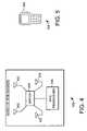
- FIG. 5is top view of an exemplary mobile RFID reader in accordance with an exemplary embodiment of the present invention.
- FIG. 6is a schematic view an exemplary RFID transceiver in accordance with an exemplary embodiment of the present invention.
- FIG. 7is a schematic view of an exemplary phase angle estimator in accordance with an exemplary embodiment of the present invention.
- FIGS. 8 and 9are table views of an exemplary data set in accordance with an exemplary embodiment of the present invention.
- FIGS. 10 and 11are graph views of an exemplary data set in accordance with an exemplary embodiment of the present invention.
- the present inventionprovides a system and method for locating objects using Radio Frequency Identification (RFID) tags.
- RFIDRadio Frequency Identification
- the system and methoduses the phase of backscatter modulated signals from the RFID tags with respect to the fundamental frequency of the transmitted signals to efficiently and accurately determine the location of objects.
- RFIDis a technology that incorporates the use of electromagnetic or electrostatic coupling in the radio frequency spectrum to identify objects to which RFID tags are affixed.
- RFID systemsin general provide the advantage of not requiring direct contact or line-of-sight scanning.
- a typical RFID systemincludes an RFID reader and a plurality of RFID tags that are affixed to the objects of interest.
- the RFID readerincludes an antenna and also includes or is coupled to a transceiver.
- the RFID readeruses the antenna and transceiver to transmit radio frequency signals to the RFID tag.
- the RFID readerhas the ability to select one or more tags by transmitting an identifier that specifies one or more of the tags from a plurality of tags. When an RFID reader selects an RFID tag, the RFID tag is put into a responsive mode, with other tags going into a muted state.
- the tagWhen put into responsive mode, the tag transmits data back to the reader by modulating a backscattered signal that is received at the RFID reader antenna.
- some tagsuse variable impedance coupled to the antenna that can be used to change the amount of energy that is reflected back by the tag. These tags can transmit data to the reader by selectively varying the impedance to modulate the backscattered signals. Similarly, these tags can be put into a “muted” or non-responsive state by selecting and maintaining an impedance value that minimizes the backscattering from that tag.
- an RFID readercan be used to select one or more RFID tags and retrieve data from the selected tags.
- RFID tagscan be used to identify and track large numbers or objects.
- RFID tagshave a relatively low per-unit cost, they have the ability to track large numbers of objects at relatively low costs.
- RFID tagsare used in a variety of commercial contexts that require a unique identification system for large numbers of items. As examples, RFID tags are used in everything from department store inventory and checkout systems to the tracking of military supplies. RFID systems are often preferred for object identification due to their increased range, lack of a line of sight requirement between a tag and its reader, and high multi-tag throughput.
- RFID tagsare available in a variety of configurations, shapes and sizes. For example, different tags for different applications typically have a shape and size appropriate for its application.
- RFID tagsare commonly categorized as active, passive or semi-passive. Active RFID tags include an internal battery used to transmit data and typically include the ability to read and write greater amounts of stored data than either passive or semi-passive tags. Passive RFID tags transmit by reflecting and absorbing energy from the RF transmissions from the reader, and use absorbed energy from the reader for data storage, retrieval, and manipulation.
- Semi-passive tagsinclude an internal battery that is used for data storage, retrieval, and manipulation, while transmitting data by reflecting and absorbing energy from the reader.
- Passive and semi-passive tagsare typically lighter and less expensive than active tags. Passive tags offer a virtually unlimited operational lifetime because they do not require a battery for operation. The trade off is that they typically have a shorter read range than active tags, and require a higher output power from the reader. It is important to note that governmental restrictions in many jurisdictions restrict reader output power to ensure safety and to minimize interference between devices that must share frequency bands.
- Passive and semi-passive tagsinclude both read-only tags that are programmable once with a unique set of data that cannot be later modified, and read/writeable tags that can be rewritten one or more times using a suitable RFID writing device.
- RFID systemscan use a variety of techniques to transmit data to and from the tag.
- the datacan be transmitted using any of a variety of modulation techniques, including amplitude modulation (AM), phase modulation (PM), and frequency modulation (FM).
- modulation techniquesincluding amplitude modulation (AM), phase modulation (PM), and frequency modulation (FM).
- FMfrequency modulation
- the data transmitted to the tagcan be encoded using any of a variety of techniques, including frequency shift keying (FSK), pulse position modulation (PPM), pulse duration modulation (PDM) and amplitude shift keying (ASK).
- FSKfrequency shift keying
- PPMpulse position modulation
- PDMpulse duration modulation
- ASKamplitude shift keying
- passive and semi-passive tagstransmit by selectively reflecting and absorbing energy from the reader, in a process generally referred to as backscatter modulation.
- the datacan be encoded using a variety of techniques.
- the datacan be encoded using FSK, where the tag absorb-reflects at one rate to represent a first state (e.g., “one”) and at another rate to represent a second state (e.g., “zero”).
- the datacan be encoded using ASK, where the tag absorb-reflects at one rate for some duration to represent a first state (e.g., “one”) and ceases back scatter modulation for another duration to represent a second state (e.g., “zero”).
- RFID systemsalso typically use a variety of different frequency ranges, including 30 KHz–500 KHz, 850 MHz–950 MHz and 2.4 GHz–2.5 GHz, depending on the regulatory spectrum allocations and performance requirements matched to various application requirements. For example, lower frequency systems typically provide better electromagnetic penetration through water while higher frequency systems do not. Lower frequency passive systems commonly operate within a few inches with small reader antennas while higher frequency systems commonly operate within several feet with similarly sized antennas. Also, lower frequency regulatory allocations are generally more widespread worldwide and typically allow more output power for passive tags than do higher frequency systems. However, where higher frequency spectrum is available for RFID, such as within FCC regulated domains, the output power is substantial and allows for robust long-range performance
- the object location system 100includes at least one RFID reader and a distance calculator.
- the RFID readertransmits a plurality of signals to the RFID tag on the object that is to be located.
- the plurality of signals transmitted to the RFID tagare selected to have different fundamental frequencies.
- the RFID tagmodulates the plurality of transmitted signals to create a plurality of backscatter modulated signals.
- the RFID readerreceives and demodulates the plurality of backscatter modulated signals.
- the distance calculatordetermines the phase in the plurality of backscatter modulated signals that were received by the RFID reader.
- the distance calculatordetermines the phase of the plurality of backscatter modulated signals. From this, the distance calculator determines the rate of change of the phase in the backscatter modulated signals versus the rate of change in the fundamental frequency of the transmitted signals and uses this information to calculate the distance to the RFID tag.
- an array of RFID readersis used to determine the object location.
- each of the RFID readerstransmits a plurality of signals to the RFID tag, with the signals from each RFID reader having different fundamental frequencies.
- the RFID tagbackscatter modulates the plurality of transmitted signals to create a plurality of backscatter modulated signals that are received by the array of RFID readers.
- the distance calculatordetermines the phase of the plurality of backscatter modulated signals. From this, the distance calculator determines the rate of change of the phase in the backscatter modulated signals with respect to the rate of change in the fundamental frequency of the transmitted signals and uses this information to calculate the distance to the RFID tag.
- a highly accurate locationcan be determined using trilateration.
- the system and methodis able to efficiently determine a highly accurate location for objects that include an RFID tag.
- the distance calculatorcould be implemented in variety of ways.
- the distance calculatorcan be fully implemented as part of each RFID reader.
- the distance calculatorcan be implemented at a central location, with the phase and fundamental frequency data used to calculate the distance transmitted to the central computer using any suitable networking technology.
- the distance calculatorcan be implemented partially in the reader, and partially at a central location. For example, the phase determinations can be made at each reader, with the final distance and location calculations made at central computer system linked to the readers.
- the plurality of signals transmitted to the RFID tagare selected to have different fundamental frequencies.
- additional signals with additional different fundamental frequenciesprovides for increased accuracy of the distance calculation.
- Phase measurements taken with transmitted signals having the same fundamental frequency as other transmitted signalscan be combined with the other phase measurements to generate a more accurate overall calculation of the phase versus frequency rate of the change.
- the RFID tag for the desired objectedis addressed. Addressing the RFID tag uses a tag ID to select one RFID tag among potentially thousands of others. Addressing puts the selected RFID tag into a responsive mode where it will modulate and backscatter received signals from the reader. Tags that are not selected will typically go into a muted state, where their reflections are intentionally minimized.
- the next step 204is to transmit a plurality of signals from the RFID reader to the tag, with the signals transmitted having a different fundamental frequency.
- a “fundamental frequency” of a signalcomprises one or more of the primary frequency components in the signal.
- the fundamental frequency of a signalcan be the frequency of the carrier signal without harmonics.
- the transmitted signalis not necessarily purely sinusoidal and thus may in fact carry harmonics due to the need for pulse shaping at the receivers.
- the plurality of transmitted signalsare received by the RFID tag.
- the selected RFID tagbackscatter modulates the plurality of transmitted signals to create a plurality of backscatter modulated signals.
- the RFID readerreceives and demodulates the plurality of backscatter modulated signals. Because of the fundamental frequency difference in the originally transmitted signal, each of the plurality of backscatter modulated signals received back at the reader will have a distinct relative phase.
- step 206the plurality of modulated signals are received back at the RFID reader.
- step 208is to determine the phase for the plurality of modulated signals.
- the phase of the received signalscan be determined in variety of ways, such as channel demodulation. Such a method will be described in greater detail below.
- the next step 210is to determine the rate of change of the phase with respect to the rate of change of the fundamental frequency.
- the rate of change of the phase with respect to the rate of change of the fundamental frequencycan be calculated from the plurality of phase measurements and plurality of transmitted signal fundamental frequencies using variety of different techniques. For example, in one application, the rate of change of phase with respect to fundamental frequency is determined by performing a linear trend fit of phase measurements and corresponding fundamental frequency values. The linear trend fit is then used to generate a more accurate rate of change or “estimated slope” of phase and frequency.
- steps 204 – 210would be recursively continued with more transmissions and phase measurements until the rate of the change could be calculated within a specified level of accuracy.
- the steps 204 – 210can be continued until the linear trend fit generates an estimated slope that is within a desired confidence level, where the confidence level can be calculated using any suitable technique such as “goodness of fit” or any other method of assessing the variance of the data trend from a straight line.
- the next step 212is to determine the distance between the RFID reader and the RFID tag using the rate of change of the phase of the received signal with respect to the rate of change of the fundamental frequency of the transmitted signal.
- the distance (D) between the RFID reader and the RFID tagcan be calculated as:
- ⁇is the change in phase of the backscatter modulated signals
- ⁇ fis the change in fundamental frequency of the transmitted signals
- cis the speed of light in meters per second or feet per second depending on the desirable units of the distance measurement.
- the method 200can be applied with an array of RFID readers to more completely determine the object location.
- each of the RFID readersperforms steps 204 and 206 , and the distance to each RFID reader is calculated in using the phase for the backscatter modulated signals received at that RFID reader and the fundamental frequencies for the originally transmitted signals.
- a highly accurate locationcan be determined using trilateration techniques.
- the method 200is able to efficiently determine a highly accurate location for objects that include an RFID tag.
- steps 204 and 206will typically be performed on a reader-by-reader basis.
- the plurality of signalswill be transmitted and received by a first reader, and a plurality of signals then transmitted and received by a second reader and so on. This provides the advantage of minimizing interferences that could result from multiple concurrent transmissions from multiple readers.
- the system and method illustrated in FIGS. 1 and 2can provide a high accuracy of object location.
- an RFID system that uses 900 MHz fundamental frequenciescan calculate the distance to within a theoretical value of 6 cm when the signal to noise ratio is relatively high.
- the system and methodcan use relatively inexpensive passive or semi-passive RFID tags, the system and method can be applied to a high number of objects at a relatively low per-unit cost.
- the RFID readertransmits a plurality of signals to the RFID tag on the object that is to be located, with the signals selected to have different fundamental frequencies.
- signals with a plurality of different frequenciesonly a least one transmitted signal with a fundamental frequency different from at least one other transmitted signal is needed.
- frequency selectioncan be randomly selected.
- the FCC and other regulatory agenciesallow up to 4 watts of transmitted power if suitable spread spectrum techniques are employed.
- the object location systemcan be implemented to randomly select transmission frequencies (i.e., channels) within one or more frequency bands and thus meet the requirements of a spread spectrum system. By randomly selecting frequencies and otherwise complying with the regulatory framework, the object location system can thus transmit to the higher power level allowed such systems. Transmitting at higher power levels increasing the effective range of the system and thus the overall performance of the system.
- CEPT in Europespecify the use of “listen before transmit” procedures instead of random hopping used in spread spectrum.
- the transmitterlistens for transmissions at a frequency channel before making its own transmission in that channel. If the transmitter detects activity in that channel, the transmitter will switch to the next frequency channel. There it will again listen to detect other transmissions before transmitting itself. This process is continued until an available channel is found and the transmission is made in that available channel.
- CSMAcarrier sense multiple access
- the object location systemcan select transmission frequencies using the “listen before transmit” procedure in such a way that it is most compatible with the regulatory framework for which the system is designed to operate. Without the ability to use such a channel selection algorithm the object location system would be limited in the power that can be used in transmitting to the RFID tag, resulting in less range and accuracy for the system.
- the array of RFID readers 300includes five separate readers. Each reader in the array is used to determine the distance from the reader to a selected object that includes an RFID tag. Typically, the readers would be spread throughout an area or facility for which object location is desired. For example, readers can be spaced in the ceilings or floors of a large warehouse and used to locate objects within the warehouse.
- the array of RFID readerstransmits a plurality of signals to the RFID tag.
- each RFID readertransmits a plurality of signals having different fundamental frequencies than at least one signal transmitted by that reader. It should be noted the fundamental frequencies of transmitted signals from different RFID readers could have the same frequencies, as they are not typically directly compared.
- the RFID tagIn response to the signals transmitted by each reader, the RFID tag produces a plurality of backscatter modulated signals that are received by the array of RFID readers.
- the distance between an RFID reader and the RFID tagis calculated using the measured phase of the backscatter modulated signals that received by that RFID reader, and the corresponding fundamental frequencies for the signals originally transmitted by that reader.
- the change in phase with respect to the change in the frequencyis used with equation 1 described above to calculate the difference.
- multiple signalsare transmitted and backscatter modulated to each RFID reader until the change in phase with respect to the change in fundamental frequency can be calculated within a specified confidence level.
- a linear trend of phase change with respect to fundamental frequency changecan be determined by performing a least squares fit analysis of the multiple phase measurements and the corresponding fundamental frequencies.
- This linear trendis a more accurate “estimated slope” of the phase change versus the frequency change.
- the accuracy of the estimated slope and the calculated distanceincreases.
- This processcan be continued until the least squares fit generates an estimated slope that is within a desired confidence level, where the confidence level can be calculated using any suitable technique such as “goodness of fit” or any other method of assessing the variance of the data trend from a straight line. This process is then continued until the distance from each reader within range of the tag is known at the desired confidence level.
- the location of the objectcan be determined using these distances, the known locations of the readers, and a suitable trilateration technique.
- the distance D 1 between the Reader 1 and the tag, distance D 2 between Reader 2 and the tag, and distance D 3 between Reader 4 and the tagcan be calculated and used to determine the location of the object relative to the known locations of the readers.
- Three distance measurementsare generally sufficient to trilaterate the position of an object, although additional measurements from other readers within range of the object can be used to provide additional accuracy.
- the location of the objectcannot be completely disambiguated. It should be emphasized that this is a simplified example of a typical RFID reader arrays, and that the number of readers can be greatly expanded depending on the size of the area to be covered and the effective range of the RFID readers.
- FIG. 4another exemplary embodiment of an RFID reader array 400 is illustrated.
- the array of RFID readersshare one RFID transceiver 406 .
- the array of RFID readers 400comprises four physically distributed antennas 402 .
- the array of RFID readers 400uses a switch 404 to selectively connect the four antennas to a single RFID transceiver 406 .
- This approachprovides the ability to reduce cost in some applications and minimize interference between RFID readers. It should be noted that in other application separate transceivers may be desirable and more cost efficient, depending primarily on the relative cost of the separate transceivers versus cost of separate antennas and cabling.
- the RFID reader array 400can be used to determine the location of objects that include RFID tags.
- the transceiver 406 and switch 404would be used to transmit a plurality of signals having different fundamental frequencies to a selected RFID tag using one or more of the antennas 402 .
- the RFID tagproduces a plurality of backscatter modulated signals that are received by antennas 402 , and selectively passed to the RFID transceiver 406 by switch 404 .
- the phase for these signalscan then be determined, and the distance between each antenna and the selected RFID tag can be calculated using the rate of change of the phase and the rate of change of the corresponding fundamental frequencies.
- the RFID reader array 400offers several advantages; the most notably being that by sharing transceivers among multiple antennas, the RFID reader array 400 is able provide the same object location ability at a reduced cost and complexity in many applications. For example, an implementation can use multiple antenna sets, each coupled through a switch to a transceiver, with the multiple transceivers coupled together to cost effectively cover a large area with RFID readers.
- This calibrationcan be done by either measuring the distance to a known tag location relative to the RFID reader, or by switching the antenna to a known backscatter reference and setting that distance to zero.
- the system and methodcan also be applied to mobile readers.
- a hand-held or other mobile readercan selectively activate RFID tags and determine the distance to the RFID tag using the methods described above. Additionally, by further determining the location of the mobile reader, the mobile reader's distance measurements can be combined with other measurements from other readers to trilaterate the location of the object. Furthermore, the mobile unit itself can be used to take multiple distance measurements from different locations that in turn can be used to trilaterate the location of the object.
- the mobile RFID reader 500is exemplary of the type of mobile readers that can be adapted for use to locate objects using the system and method described above.
- the mobile RFID reader 500is thus used to determine the location of objects that include an RFID tag.
- the RFID reader 500itself includes an RFID tag 502 .
- the RFID tag 502means that the location of the mobile RFID reader 500 can be determined with other RFID readers using the system and methods described above. With the position of the mobile RFID reader 500 determined, the mobile RFID reader 500 can be used as one of an array of RFID readers to accurately determine the location of an object that includes another RFID tag.
- the RFID tag on the mobile readercould be implemented by emulating the behavior of a tag using an antenna, transistor, rectifier and the existing microprocessor on the mobile reader.
- the transistoris driven by the microprocessor to create backscatter modulation that imitates a conventional RFID tag.
- the mobile RFID reader 500can communicate with the system using any suitable protocols and methods.
- the mobile RFID reader 500can communicate using telephony communication standards, or using other wireless protocols such as WLAN radios that use IEEE 802.11(b).
- the location of the mobile reader 500can be determined using the WLAN transmissions to and from the reader.
- the trade-offis that location based on phase and frequency differences of modulated backscatter signals are much more accurate than those based on half-duplex systems such as WLANs that do not produce accurate phase references.
- the RFID transceiver 600is illustrated in accordance with an exemplary embodiment of the present invention.
- the RFID transceiver 600is an example of the type of RFID transceiver that can be used in RFID reader(s) in the object location system and method.
- the RFID transceiver 600is designed to transmit and receive signals to and from a selected RFID tag.
- the RFID transceiver 600includes a quadrature demodulator.
- Quadrature demodulatorsare typically used in quadrature amplitude modulation (QAM) systems that combine two amplitude-modulated signals into a single channel, with two carriers (“I” and “Q”) having the same fundamental frequency but differing in phase, typically by 90 degrees.
- QAMquadrature amplitude modulation
- the RFID transceiver 600uses a quadrature demodulator to provide a mechanism for determining the phase of the received backscatter modulated signal relative to the transmitted signal. Specifically, the AC amplitudes of the separately demodulated “I” and “Q” channels will be used to determine the relative phase of the received backscattered signal.
- thisis just one example, and other transceiver implementations could be used with other demodulation techniques.
- the RFID transceiver 600includes a modulator 602 , a variable gain amplifier 604 , a power amplifier 606 , a band-pass filter 608 , a circulator 610 , a band pass filter 614 , an automatic gain control 616 , demodulators 620 and 622 , band pass filters 624 and 626 , buffers 628 and 630 , and phase-locked-loop oscillator 632 .
- the transceiver 600transmits signals and receives signals through the antenna 612 .
- additional antennascould be added using a switch as was described with reference to FIG. 4 above.
- the transceiver 600transmits to and receives signals from selected RFID tags that are in the responsive mode.
- the transceiverencodes transmission data onto a carrier waveform generated by oscillator 632 and broadcasts the signal through the antenna 612 to the RFID tag.
- the transceiver 600uses the modulator 602 and the variable gain amplifier 604 to modulate the carrier signal generated by oscillator 632 with the transmission data (TX Data).
- the power amplifier 606amplifies the modulated signal, which is passed through band pass filter 608 .
- the circulator 610acts as a selective coupler element to antenna 612 , where the modulated signal is transmitted to the RFID tags, and substantially isolated from the directly connected receiver.
- the transmitterceases carrier modulation and the receiver receives the modulated backscattered signal via the antenna, strips the signal from the carrier signal, and converts the stripped signal into an in phase “I” component and a quadrature “Q” component.
- These componentscan then be independently digitized and sent to a processor for bit recovery, where they can be interpreted by the RFID reader and/or other related systems. Additionally, these components can be used to determine the phase of the received signal relative to the originally transmitted signal, with the phase of the originally transmitted signal serving as a reference measurement to determine the change in phase between the different received signals.
- the transceiver 600receives backscatter modulated signals from the RFID tag via antenna 612 .
- the circulator 610again acts as a selective coupler element, this time coupling the antenna 612 to the band pass filter 614 .
- the received signalmay then be amplified by the automatic gain control 616 .
- This amplified signalmay then be carrier-demodulated in quadrature using mixers 620 and 622 and phase shifter 618 , which collectively provide two demodulators. This demodulation results in an in-phase signal I AC+DC and the quadrature signal Q AC+DC .
- Each of these signalsis passed through a corresponding band-pass-filter ( 624 and 626 ) and buffers ( 628 and 630 ) before the separate signals are further processed.
- the demodulatoruses the same signal generated by the phase-lock-loop oscillator 632 that is used for carrier generation of the originally transmitted signal.
- the phase of this signalcan serve as a reference by which the phase change of the received signals can be measured.
- the relative change in phase between those received signalscan be calculated.
- determining the phase difference of the received backscatter modulated signal compared to the originally transmitted signalsprovides a mechanism for determining the rate of change in the phase of the plurality of backscatter modulated signals.
- RFID receiverthat can be used for object location.
- suitable receiversuse separate transmit and receiver configurations.
- suitable receiversreplace the circulator component with a directional coupler.
- the advantage of a directional coupleris much lower cost and smaller size but the disadvantage is significant signal loss, hence much lower performance
- the phasecan be determined and used to calculate the distance to the object.
- the distance calculatordetermines the phase in the plurality of backscatter-modulated signals that were received by the RFID reader. From the change in phase and the corresponding change in fundamental frequency in the originally transmitted signals, the distance calculator calculates the distance to the RFID tag using equation 1. The phase differences can then be determined using a variety of different techniques and devices. As one example, the phase of each backscattered signal is referenced to the phase of the originally transmitted signal.
- One method for determining the phase of the received signalsis to measure the AC amplitude of both I and Q channels and use those measurements to determine the phase angle. That is, the peak-to-peak AC amplitude of the I and Q channel can be averaged over some predetermined time period.
- the relative phase ⁇ of the received signal as compared to the carrier phasecan be determined as:
- Q AMPis the average AC amplitude in the Q channel and I AMP is the average AC amplitude in the I channel.
- phase angle estimator 700uses the mathematical technique of matrix rotation to determine the phase of the signals.
- the I channel signal I AC+DC quadrature signal Q AC+DCare passed to a DC offset remover 702 . This removes the DC portion of the I and Q channel signals, leaving only the AC portions of each signal. Additionally, noise rejection can be done at this point as well.
- the I channel signal I AC an quadrature signal Q ACare then passed to matrix rotation mechanism 704 .
- the AC amplitudes of these signalsare loaded into the matrix. Again, these AC amplitudes can be determined by averaging the AC amplitude over a selected time period.
- the matrixis then mathematically rotated until the signal in the Q channel is minimized and the signal in the I channel is maximized.
- the angle of matrix rotation needed to maximize the signal in the I channelis equal to the relative phase of the received signal.
- the minimization of signal in the Q channelis done using a least squares estimate minimization technique. Of course, other suitable techniques could also be used.
- This methodalso has the advantage of moving all of the signal to the I channel, where the information in the channel can be recovered and decoded using any suitable technique. Again, with the relative phase of multiple backscattered signals calculated using the phase angle estimator, the phase change between those signals could be calculated and used to determine the distance to the tag.
- phase unwrappingthe process of determining the actual, nominal phase values from the wrapped values.
- phase unwrappingis a technique that can be used to determine the nominal phase change over a linear span of corresponding fundamental frequencies.
- One method of phase unwrappingis to linearize the phase shift from the wrapped values. Specifically, the phase unwrapping is accomplished by adding or subtracting multiples of 2 ⁇ until the phase measurement in question shows a consistent trend over a frequency span.
- phase unwrappingwhen a set of monotonically increasing fundamental frequencies are used, a monotonic set of phase measurements should result after accounting for any noise. For particular phase measurements that do not follow the monotonic trend, they can be unwrapped by adding or subtracting multiples of 2 ⁇ until they show a linear trend over a linear frequency span.
- phase unwrapping algorithmsare available that can be adapted for this use, such as signal processing tools available in MATLAB.
- a table 800illustrates an exemplary data set from which the distance to an RFID tag can be determined using an exemplary embodiment of the present invention.
- the table 800lists 14 transmitted signal fundamental frequencies and a corresponding 14 measured relative phase measurements. It should first be noted that this is just one example data set, and that typical data sets could include more or less data points. It should also be noted that while example data set shows equal distances between fundamental frequencies, that this will not be the case in many applications.
- the frequency order of the transmitted signalswas randomly selected. Again, when random frequency hopping is used the system operates as spread spectrum system and can transmit with increased power under current regulations. Again, this is just one example, and in other cases different frequency hopping procedures can be used.
- phase measurements illustrated in table 800are wrapped, again meaning that the phase measurements are limited to values between zero and 2 ⁇ radians. These values thus do not represent the actual relative phase values, and to accurately calculate the distance it is desirable to unwrap the phase measurements.
- a table 900lists the 14 transmitted signal fundamental frequencies in order of fundamental frequency and a corresponding unwrapped 14 measured relative phases. These unwrapped phase values correspond to the actual relative phase of the received backscatter modulated signals. Again, these unwrapped phase values can be determined by a variety of phase unwrapping techniques, such as adding multiples of 2 ⁇ until a consistent linear phase trend is recovered.
- a graph 1000illustrates the wrapped phase measurements and the unwrapped phase measurements of tables 800 and 900 .
- the unwrapping of phase measurementsresults in phase measurements that follow a consistent trend.
- the underlying phasecan be determined even in the presence of significant noise and multi-reflections.
- the distancecan be determined by calculating the rate of change of the phase with respect to the rate of change of the fundamental frequency.
- a linear trend fit of the unwrapped phase measurements the fundamental frequenciescan be performed to determine the rate of change.
- FIG. 11a graph 1100 illustrates the unwrapped phase measurements of table 900 and graph 1000 along with an exemplary linear trend calculated from the phase measurements.
- the linear trendcan be calculated from the data using a variety of techniques such as least squares fit. When calculated the linear trend gives a more accurate calculation of the phase change with respect to the frequency change in the form of the slope of the trend fit line.
- the slope of the linear trendis 9.01E-07 radians/hertz.
- the slope of the linear trend fit linecan be used as ⁇ / ⁇ f in equation 1 to calculate the distance.
- using the slope of the linear trend fit line in equation 1gives a distance measurement of 21.4 meters.
- the linear fit methodis able to overcome noise in the data such as noise created by multi-path reflections, interference and non-coherent transmissions. Again, this is just one specific example of how a linear trend fit can be used to determine the rate of change of the phase and frequency to calculate the distance to an object with an RFID tag.
- the present inventionthus system and method for locating objects using RFID tags.
- the system and methoduses one or more RFID readers and a distance calculator to efficiently and accurately determine the location of objects that include an RFID tag.
- the RFID readertransmits a plurality of signals to the RFID tag, with the plurality of signals having different frequencies.
- the RFID tagbackscatter modulates the plurality of transmitted signals to create a plurality of backscatter modulated signals.
- the RFID readerreceives and demodulates the plurality of backscatter modulated signals.
- the distance calculatordetermines the phase of the plurality of backscatter modulated signals and determines a rate of change of the phase in the backscatter modulated signals versus the rate of change in the fundamental frequency of the transmitted signals.
- the distance calculatoruses the rates of change information to calculate the distance to the RFID tag.
Landscapes
- Engineering & Computer Science (AREA)
- Radar, Positioning & Navigation (AREA)
- Remote Sensing (AREA)
- Computer Networks & Wireless Communication (AREA)
- Physics & Mathematics (AREA)
- General Physics & Mathematics (AREA)
- Radar Systems Or Details Thereof (AREA)
- Near-Field Transmission Systems (AREA)
Abstract
Description
Claims (51)
Priority Applications (6)
| Application Number | Priority Date | Filing Date | Title |
|---|---|---|---|
| US10/791,329US7119738B2 (en) | 2004-03-01 | 2004-03-01 | Object location system and method using RFID |
| PCT/US2005/005897WO2005085899A1 (en) | 2004-03-01 | 2005-02-25 | Object location system and method using rfid |
| CA2557341ACA2557341C (en) | 2004-03-01 | 2005-02-25 | Object location system and method using rfid |
| EP05723669.7AEP1721187B1 (en) | 2004-03-01 | 2005-02-25 | Object location system and method using rfid |
| AU2005218459AAU2005218459B2 (en) | 2004-03-01 | 2005-02-25 | Object location system using RFID |
| AU2010200808AAU2010200808B2 (en) | 2004-03-01 | 2010-03-03 | Object Location Method and System Using RFID |
Applications Claiming Priority (1)
| Application Number | Priority Date | Filing Date | Title |
|---|---|---|---|
| US10/791,329US7119738B2 (en) | 2004-03-01 | 2004-03-01 | Object location system and method using RFID |
Publications (2)
| Publication Number | Publication Date |
|---|---|
| US20050190098A1 US20050190098A1 (en) | 2005-09-01 |
| US7119738B2true US7119738B2 (en) | 2006-10-10 |
Family
ID=34887587
Family Applications (1)
| Application Number | Title | Priority Date | Filing Date |
|---|---|---|---|
| US10/791,329Expired - LifetimeUS7119738B2 (en) | 2004-03-01 | 2004-03-01 | Object location system and method using RFID |
Country Status (5)
| Country | Link |
|---|---|
| US (1) | US7119738B2 (en) |
| EP (1) | EP1721187B1 (en) |
| AU (2) | AU2005218459B2 (en) |
| CA (1) | CA2557341C (en) |
| WO (1) | WO2005085899A1 (en) |
Cited By (76)
| Publication number | Priority date | Publication date | Assignee | Title |
|---|---|---|---|---|
| US20050204167A1 (en)* | 2004-03-15 | 2005-09-15 | Conlin Michael T. | Systems and methods for access control |
| US20050258966A1 (en)* | 2004-05-18 | 2005-11-24 | Quan Ralph W | Antenna array for an RFID reader compatible with transponders operating at different carrier frequencies |
| US20060071790A1 (en)* | 2004-09-29 | 2006-04-06 | Duron Mark W | Reverse infrastructure location system and method |
| US20060107307A1 (en)* | 2004-09-29 | 2006-05-18 | Michael Knox | Object location based security using RFID |
| US20060173750A1 (en)* | 2004-12-30 | 2006-08-03 | Naley Martin R | System and method for controlling access to a local inventory storage system via a remote e-commerce application |
| US20060206927A1 (en)* | 2005-03-08 | 2006-09-14 | Xceedid | Systems and methods for dual reader emulation |
| US20060220861A1 (en)* | 2005-02-28 | 2006-10-05 | Anatoli Stobbe | Method for locating a detection microchip |
| US20060226213A1 (en)* | 2005-04-07 | 2006-10-12 | Intel Corporation | Methods and apparatus for providing a radio frequency identification system |
| US20060261968A1 (en)* | 2005-05-23 | 2006-11-23 | Fujitsu Limited | Signal incoming direction estimation apparatus |
| US20070001814A1 (en)* | 2005-06-14 | 2007-01-04 | Steinke Kurt E | Wireless tag ranging |
| US20070052541A1 (en)* | 2005-09-07 | 2007-03-08 | Siemens Aktiengesellschaft | System for detecting a local utilizaiton state of a technical system |
| US20070073513A1 (en)* | 2005-09-29 | 2007-03-29 | Joshua Posamentier | Determining RFID tag location |
| US20070088498A1 (en)* | 2005-10-18 | 2007-04-19 | International Business Machines Corporation | Method, apparatus and computer program for determining the location of a user in an area |
| US20070103303A1 (en)* | 2005-11-07 | 2007-05-10 | Radiofy Llc, A California Limited Liability Company | Wireless RFID networking systems and methods |
| US20070132582A1 (en)* | 2005-12-13 | 2007-06-14 | National Institute Of Advanced Industrial Science And Technology | Mobile object detection method and detection system |
| US7232069B1 (en)* | 2004-06-16 | 2007-06-19 | Ncr Corporation | Methods and apparatus for disabling, enabling or setting the range of radio frequency identification devices |
| US7265675B1 (en)* | 2005-03-01 | 2007-09-04 | Alien Technology Corporation | Multistatic antenna configuration for radio frequency identification (RFID) systems |
| US20070268136A1 (en)* | 2006-05-17 | 2007-11-22 | Ncr Corporation | Methods and apparatus for determining and using distance information for distances between RFID transceivers and RFID tags |
| US20080079626A1 (en)* | 2006-10-03 | 2008-04-03 | Karsten Manufacturing Corporation | Methods and Apparatus for Detecting Motion Associated with Sports Equipment. |
| US20080143584A1 (en)* | 2006-12-18 | 2008-06-19 | Radiofy Llc, A California Limited Liability Company | Method and system for determining the distance between an RFID reader and an RFID tag using phase |
| US20080143482A1 (en)* | 2006-12-18 | 2008-06-19 | Radiofy Llc, A California Limited Liability Company | RFID location systems and methods |
| US20080300044A1 (en)* | 2007-05-29 | 2008-12-04 | Semiconductor Energy Laboratory Co., Ltd. | Card game machine |
| US7495544B2 (en)* | 2003-02-03 | 2009-02-24 | Ingrid, Inc. | Component diversity in a RFID security network |
| US7511614B2 (en) | 2003-02-03 | 2009-03-31 | Ingrid, Inc. | Portable telephone in a security network |
| US7532114B2 (en) | 2003-02-03 | 2009-05-12 | Ingrid, Inc. | Fixed part-portable part communications network for a security network |
| US20090146831A1 (en)* | 2007-09-11 | 2009-06-11 | Federal Network System Llc | Wireless enabled device tracking system and method |
| US20090207024A1 (en)* | 2008-02-14 | 2009-08-20 | Intermec Ip Corp. | Utilization of motion and spatial identification in mobile rfid interrogator |
| US20090303006A1 (en)* | 2008-06-06 | 2009-12-10 | Eggers Patrick Claus Friedrich | System and method for wireless communications |
| US20100019955A1 (en)* | 2008-07-28 | 2010-01-28 | Durgin Gregory D | Method and Apparatus for Location Determination Using Reflected Interferometry |
| US20100039228A1 (en)* | 2008-04-14 | 2010-02-18 | Ramin Sadr | Radio frequency identification tag location estimation and tracking system and method |
| US20100097237A1 (en)* | 2007-03-01 | 2010-04-22 | Peter Nygaard Christiansen | Safety device |
| US20100109844A1 (en)* | 2008-11-03 | 2010-05-06 | Thingmagic, Inc. | Methods and Apparatuses For RFID Tag Range Determination |
| US20100148931A1 (en)* | 2008-12-12 | 2010-06-17 | Ravikanth Srinivasa Pappu | Radio devices and communications |
| US20100219953A1 (en)* | 2009-02-27 | 2010-09-02 | Rf Controls, Llc | Radio Frequency Environment Object Monitoring System and Methods of Use |
| US20100225480A1 (en)* | 2007-09-11 | 2010-09-09 | Rf Controls, Llc | Radio frequency signal acquisition and source location system |
| US20100271263A1 (en)* | 2008-03-31 | 2010-10-28 | Mehran Moshfeghi | Method and System for Determining the Position of a Mobile Station |
| US20100283683A1 (en)* | 2006-07-20 | 2010-11-11 | Semiconductor Energy Laboratory Co., Ltd. | Position information detection system and position information detection method |
| US20100309051A1 (en)* | 2008-03-31 | 2010-12-09 | Mehran Moshfeghi | Method and system for determining the position of a mobile device |
| US20100328073A1 (en)* | 2009-06-30 | 2010-12-30 | Intermec Ip Corp. | Method and system to determine the position, orientation, size, and movement of rfid tagged objects |
| US20110032079A1 (en)* | 2009-08-10 | 2011-02-10 | Rf Controls, Llc | Antenna switching arrangement |
| US20110043407A1 (en)* | 2008-03-31 | 2011-02-24 | GOLBA Radiofy LLC, a California Limited Liability Company | Methods and systems for determining the location of an electronic device |
| US20110063113A1 (en)* | 2009-09-10 | 2011-03-17 | Rf Controls, Llc | Calibration and Operational Assurance Method and Apparatus for RFID Object Monitoring System |
| US20110109442A1 (en)* | 2009-11-12 | 2011-05-12 | George Pavlov | Passive RFID tag reader/locator |
| US20110221633A1 (en)* | 2010-03-11 | 2011-09-15 | Benjamin Bela Schramm | Methods and systems for determining the distance between two objects using wirelessly transmitted pulses |
| US20110227722A1 (en)* | 2007-09-26 | 2011-09-22 | Salvat Jr Roberto | Tracking System And Device |
| US8044804B1 (en)* | 2007-06-01 | 2011-10-25 | Hewlett-Packard Development Company, L. P. | Localizing a tag using variable signal range |
| WO2012044524A1 (en) | 2010-09-28 | 2012-04-05 | Symbol Technologies, Inc. | Method and reader device for identifying a location of a radio frequency identification (rfid) tag |
| US20120146836A1 (en)* | 2008-10-30 | 2012-06-14 | Nederlandse Organisatie Voor Toegepast- Natuurwetenschappelijk Onderzoek Tno | Measurement agent, a tag, a method for measuring, a method for serving measuring and a computer program product |
| US8279069B2 (en) | 2002-07-09 | 2012-10-02 | Automated Tracking Solutions, Llc | Method and apparatus for tracking objects and people |
| US20120326930A1 (en)* | 2008-12-11 | 2012-12-27 | O'hern William A | Devices, systems and methods for portable device location |
| EP2779020A3 (en)* | 2013-03-14 | 2014-10-29 | Intermec IP Corp. | Synthetic aperture RFID handheld with tag location capability |
| US8994504B1 (en) | 2008-02-14 | 2015-03-31 | Intermec Ip Corp. | Utilization of motion and spatial identification in mobile RFID interrogator |
| US9007178B2 (en) | 2008-02-14 | 2015-04-14 | Intermec Ip Corp. | Utilization of motion and spatial identification in RFID systems |
| US9047522B1 (en) | 2008-02-14 | 2015-06-02 | Intermec Ip Corp. | Utilization of motion and spatial identification in mobile RFID interrogator |
| US20150381269A1 (en)* | 2014-06-27 | 2015-12-31 | Google Inc. | Streaming display data from a mobile device using backscatter communications |
| US20160102964A1 (en)* | 2014-10-09 | 2016-04-14 | Lexmark International, Inc. | Methods and Systems for Estimating Distance of a Radio Frequency Identification Tag |
| US9459343B2 (en) | 2012-03-22 | 2016-10-04 | Intermec Ip Corp. | Synthetic aperture RFID handheld with tag location capability |
| US9465827B1 (en) | 2013-03-05 | 2016-10-11 | Emc Corporation | Proximity based management services |
| US9747480B2 (en) | 2011-12-05 | 2017-08-29 | Adasa Inc. | RFID and robots for multichannel shopping |
| US9780435B2 (en) | 2011-12-05 | 2017-10-03 | Adasa Inc. | Aerial inventory antenna |
| US9829560B2 (en) | 2008-03-31 | 2017-11-28 | Golba Llc | Determining the position of a mobile device using the characteristics of received signals and a reference database |
| US9872135B2 (en)* | 2014-12-31 | 2018-01-16 | Intermec Ip Corp. | Systems and methods for displaying location information for RFID tags |
| US9883337B2 (en) | 2015-04-24 | 2018-01-30 | Mijix, Inc. | Location based services for RFID and sensor networks |
| US9924244B2 (en) | 2010-04-14 | 2018-03-20 | Mojix, Inc. | Systems and methods for detecting patterns in spatio-temporal data collected using an RFID system |
| US9963912B2 (en) | 2012-12-12 | 2018-05-08 | Life Technologies Corporation | Self-locking door and product dispensing enclosure having a self-locking door |
| US9977112B2 (en) | 2010-09-27 | 2018-05-22 | University Of Virginia Patent Foundation | Object localization with RFID infrastructure |
| US9983299B2 (en) | 2013-03-15 | 2018-05-29 | Mojix, Inc. | Systems and methods for compressive sensing ranging evaluation |
| US10050330B2 (en) | 2011-12-05 | 2018-08-14 | Adasa Inc. | Aerial inventory antenna |
| US10209358B2 (en)* | 2016-03-03 | 2019-02-19 | Canon Kabushiki Kaisha | Object detection using sonic waves |
| US10295661B2 (en) | 2015-10-16 | 2019-05-21 | Rflocus Inc. | Storage medium location detection system and program |
| US10401488B2 (en) | 2013-06-26 | 2019-09-03 | University Of Virginia Patent Foundation | Real-time RFID localization using uniform, high-performance tags and related method thereof |
| US10476130B2 (en) | 2011-12-05 | 2019-11-12 | Adasa Inc. | Aerial inventory antenna |
| US10614413B2 (en) | 2014-10-24 | 2020-04-07 | Life Technologies Corporation | Inventory management system and method of use |
| US10846497B2 (en) | 2011-12-05 | 2020-11-24 | Adasa Inc. | Holonomic RFID reader |
| US10970498B2 (en)* | 2019-04-25 | 2021-04-06 | Palo Alto Research Center Incorporated | Chipless RFID decoding system and method |
| US11093722B2 (en) | 2011-12-05 | 2021-08-17 | Adasa Inc. | Holonomic RFID reader |
Families Citing this family (96)
| Publication number | Priority date | Publication date | Assignee | Title |
|---|---|---|---|---|
| US8077040B2 (en) | 2000-01-24 | 2011-12-13 | Nextreme, Llc | RF-enabled pallet |
| US7342496B2 (en) | 2000-01-24 | 2008-03-11 | Nextreme Llc | RF-enabled pallet |
| FR2853982B1 (en)* | 2003-04-17 | 2009-05-22 | Alcea | METHOD AND DEVICE FOR DETECTION AND IDENTIFICATION OF OBJECTS, SECURE CONTAINERS AND SYSTEMS HAVING SUCH DEVICE, AND OBJECTS ADAPTED FOR THIS METHOD |
| US7404520B2 (en)* | 2004-04-28 | 2008-07-29 | Symbol Technologies, Inc. | System and method for providing location information in transaction processing |
| US7339476B2 (en) | 2004-11-10 | 2008-03-04 | Rockwell Automation Technologies, Inc. | Systems and methods that integrate radio frequency identification (RFID) technology with industrial controllers |
| US7551081B2 (en) | 2004-11-10 | 2009-06-23 | Rockwell Automation Technologies, Inc. | Systems and methods that integrate radio frequency identification (RFID) technology with agent-based control systems |
| US7636044B1 (en) | 2005-05-13 | 2009-12-22 | Rockwell Automation Technologies, Inc. | RFID tag programming, printing application, and supply chain/global registration architecture |
| US7616117B2 (en) | 2005-07-19 | 2009-11-10 | Rockwell Automation Technologies, Inc. | Reconciliation mechanism using RFID and sensors |
| US7388491B2 (en)* | 2005-07-20 | 2008-06-17 | Rockwell Automation Technologies, Inc. | Mobile RFID reader with integrated location awareness for material tracking and management |
| US7764191B2 (en) | 2005-07-26 | 2010-07-27 | Rockwell Automation Technologies, Inc. | RFID tag data affecting automation controller with internal database |
| US8260948B2 (en) | 2005-08-10 | 2012-09-04 | Rockwell Automation Technologies, Inc. | Enhanced controller utilizing RFID technology |
| US20070206704A1 (en)* | 2006-03-03 | 2007-09-06 | Applied Wireless Identification Group, Inc. | RFID reader with adaptive carrier cancellation |
| US7510110B2 (en)* | 2005-09-08 | 2009-03-31 | Rockwell Automation Technologies, Inc. | RFID architecture in an industrial controller environment |
| US7931197B2 (en) | 2005-09-20 | 2011-04-26 | Rockwell Automation Technologies, Inc. | RFID-based product manufacturing and lifecycle management |
| US7446662B1 (en) | 2005-09-26 | 2008-11-04 | Rockwell Automation Technologies, Inc. | Intelligent RFID tag for magnetic field mapping |
| US8025227B2 (en) | 2005-09-30 | 2011-09-27 | Rockwell Automation Technologies, Inc. | Access to distributed databases via pointer stored in RFID tag |
| NL1030317C2 (en)* | 2005-10-31 | 2007-05-03 | Enraf Bv | Device for determining the level of a liquid with the aid of a radar antenna, and such a radar antenna. |
| US7328114B2 (en)* | 2005-12-09 | 2008-02-05 | General Electric Company | Methods and systems for measuring a rate of change of frequency |
| KR100791025B1 (en)* | 2005-12-31 | 2008-01-03 | 주식회사 유컴테크놀러지 | Air Channel Access Method and Tag Zone Partitioning Method in Mobile RF ID System |
| KR100666340B1 (en)* | 2006-01-17 | 2007-01-09 | 인티그런트 테크놀로지즈(주) | Radio Identification Reader and Radio Identification System. |
| NL1031209C2 (en)* | 2006-02-22 | 2007-08-24 | Enraf Bv | Method and device for accurately determining the level L of a liquid with the aid of radar signals radiated to the liquid level and radar signals reflected by the liquid level. |
| US7714773B2 (en)* | 2006-03-28 | 2010-05-11 | Omron Corporation | RFID tag distance measuring system and reader |
| WO2007136022A1 (en)* | 2006-05-22 | 2007-11-29 | Semiconductor Energy Laboratory Co., Ltd. | Semiconductor device and position detection system using semiconductor device |
| US9087226B2 (en)* | 2006-06-09 | 2015-07-21 | Intelleflex Corporation | System, method and computer program product for calibrating interrogator signal strength and/or tag response range setting |
| JP4206108B2 (en)* | 2006-07-28 | 2009-01-07 | 東芝テック株式会社 | Wireless tag reader / writer |
| WO2008024815A2 (en)* | 2006-08-22 | 2008-02-28 | Dimensions Imaging | Method and system for providing tolerance to interference and obstructions of line of sight observation |
| WO2008041662A1 (en)* | 2006-09-26 | 2008-04-10 | Semiconductor Energy Laboratory Co., Ltd. | Article management method and article management system |
| US7639143B2 (en)* | 2006-09-29 | 2009-12-29 | Intel Corporation | Method and apparatus for visospatial and motor skills testing of patient |
| WO2008059742A1 (en)* | 2006-11-14 | 2008-05-22 | Semiconductor Energy Laboratory Co., Ltd. | Article management system |
| EP1928098A3 (en)* | 2006-11-28 | 2013-07-03 | Samsung Electronics Co., Ltd. | Method and apparatus for signal detecting in radio frequency identification system |
| JP5179858B2 (en)* | 2007-01-06 | 2013-04-10 | 株式会社半導体エネルギー研究所 | Semiconductor device |
| US8143996B2 (en) | 2007-01-08 | 2012-03-27 | The Curators Of The University Of Missouri | Decentralized radio frequency identification system |
| US7752089B2 (en) | 2007-03-02 | 2010-07-06 | The Curators Of The University Of Missouri | Adaptive inventory management system |
| US20080297319A1 (en)* | 2007-05-29 | 2008-12-04 | Semiconductor Energy Laboratory Co., Ltd. | Article management system |
| NL1034327C2 (en)* | 2007-09-04 | 2009-03-05 | Enraf Bv | Method and device for determining the level L of a liquid within a certain measuring range with the aid of radar signals radiated to the liquid level and radar signals reflected by the liquid level. |
| US7884753B2 (en)* | 2008-02-04 | 2011-02-08 | Honeywell International Inc. | Apparatus and method for ranging of a wireless transceiver with a switching antenna |
| US7965182B2 (en) | 2008-02-08 | 2011-06-21 | Honeywell International Inc. | Apparatus and method for providing a failsafe-enabled wireless device |
| US8159358B2 (en)* | 2008-05-12 | 2012-04-17 | Enraf B.V. | Apparatus and method for storage tank hatch monitoring in an inventory management system |
| US7891229B2 (en)* | 2008-05-13 | 2011-02-22 | Enraf B.V. | Method and apparatus for real-time calibration of a liquid storage tank level gauge |
| US8120486B2 (en)* | 2008-06-10 | 2012-02-21 | Symbol Technologies, Inc. | Methods and systems for tracking RFID devices |
| JP5195652B2 (en)* | 2008-06-11 | 2013-05-08 | ソニー株式会社 | Signal processing apparatus, signal processing method, and program |
| US8631696B2 (en)* | 2008-08-12 | 2014-01-21 | Enraf, B.V. | Apparatus and method for monitoring tanks in an inventory management system |
| US8659472B2 (en)* | 2008-09-18 | 2014-02-25 | Enraf B.V. | Method and apparatus for highly accurate higher frequency signal generation and related level gauge |
| US8224594B2 (en)* | 2008-09-18 | 2012-07-17 | Enraf B.V. | Apparatus and method for dynamic peak detection, identification, and tracking in level gauging applications |
| US8271212B2 (en)* | 2008-09-18 | 2012-09-18 | Enraf B.V. | Method for robust gauging accuracy for level gauges under mismatch and large opening effects in stillpipes and related apparatus |
| US8463079B2 (en)* | 2008-12-16 | 2013-06-11 | Intermec Ip Corp. | Method and apparatus for geometrical measurement using an optical device such as a barcode and/or RFID scanner |
| US8537014B2 (en)* | 2008-12-19 | 2013-09-17 | Symbol Technologies, Inc. | RFID tag movement determination |
| DE102009060591A1 (en) | 2008-12-30 | 2010-07-08 | Atmel Automotive Gmbh | Transmitter-receiver circuit and method for distance measurement between a first node and a second node of a radio network |
| DE102009060593A1 (en)* | 2008-12-30 | 2010-07-08 | Atmel Automotive Gmbh | System, method and circuit for distance measurement between two nodes of a radio network |
| DE102009060592B4 (en)* | 2008-12-30 | 2012-06-06 | Atmel Automotive Gmbh | Circuit and method for distance measurement between two nodes of a radio network |
| DE102009060505B4 (en)* | 2008-12-30 | 2011-09-01 | Atmel Automotive Gmbh | Circuit, system and method for communication between two nodes of a radio network |
| DE102009009846A1 (en)* | 2009-02-20 | 2010-09-02 | Bundesdruckerei Gmbh | Improved card reader for contactless readable cards and method of operating such a card reader |
| US8234084B2 (en)* | 2009-03-17 | 2012-07-31 | Enraf B.V. | Apparatus and method for automatic gauge reading in an inventory control and management system |
| US8860551B2 (en) | 2009-03-23 | 2014-10-14 | International Business Machines Corporation | Automated RFID reader detection |
| FI20096076A0 (en)* | 2009-10-20 | 2009-10-20 | Valtion Teknillinen | Object location method and system |
| GB201006904D0 (en) | 2010-04-26 | 2010-06-09 | Cambridge Entpr Ltd | RFID TAG location systems |
| KR20110127968A (en)* | 2010-05-20 | 2011-11-28 | 엘에스산전 주식회사 | Remote control transceiver and method using R FID |
| US8997549B2 (en) | 2010-09-23 | 2015-04-07 | Honeywell International Inc. | Apparatus and methods for automatically testing a servo gauge in an inventory management system |
| US8670945B2 (en) | 2010-09-30 | 2014-03-11 | Honeywell International Inc. | Apparatus and method for product movement planning to support safety monitoring in inventory management systems |
| CN102221663B (en)* | 2011-05-09 | 2013-04-03 | 长沙河野电气科技有限公司 | Passive radio frequency tag reversed modulating performance testing method and apparatus thereof |
| ITMI20111249A1 (en)* | 2011-07-05 | 2013-01-06 | Uniteam S P A | METHOD OF GEOLOCALIZATION OF MOBILE ELEMENTS IN DELIMITED AREAS AND ELECTRONIC SYSTEM IMPLEMENTING THE SAME |
| US9046406B2 (en) | 2012-04-11 | 2015-06-02 | Honeywell International Inc. | Advanced antenna protection for radars in level gauging and other applications |
| US10321127B2 (en) | 2012-08-20 | 2019-06-11 | Intermec Ip Corp. | Volume dimensioning system calibration systems and methods |
| NO336454B1 (en)* | 2012-08-31 | 2015-08-24 | Id Tag Technology Group As | Device, system and method for identifying objects in a digital image, as well as transponder device |
| US9779596B2 (en)* | 2012-10-24 | 2017-10-03 | Apple Inc. | Devices and methods for locating accessories of an electronic device |
| US9213873B2 (en) | 2013-03-22 | 2015-12-15 | Symbol Technologies, Llc | Determining movement of a radio frequency identification tag using a phase difference/frequency model |
| US9336074B2 (en) | 2013-07-26 | 2016-05-10 | Honeywell International Inc. | Apparatus and method for detecting a fault with a clock source |
| US9836936B1 (en)* | 2014-08-01 | 2017-12-05 | C & A Associates, Inc. | Object tracking system |
| WO2016065314A1 (en) | 2014-10-23 | 2016-04-28 | Automaton, Inc. | Systems and methods for rfid tag locating using constructive interference |
| US9780944B2 (en) | 2015-07-31 | 2017-10-03 | Atmel Corporation | Frequency control data synchronization |
| US11744470B2 (en) | 2017-06-16 | 2023-09-05 | Cornell University | Methods and systems for electromagnetic near-field coherent sensing |
| EP3794497B1 (en) | 2018-05-14 | 2023-07-05 | Cornell University | Collaborative rfid reader using code divisional multiple access (cdma) and methods for same |
| US11641563B2 (en) | 2018-09-28 | 2023-05-02 | Apple Inc. | System and method for locating wireless accessories |
| KR101954877B1 (en)* | 2018-10-10 | 2019-03-06 | 김경원 | A terminal for tracking the location of an article set by an individual, a location tracking system and a method using a terminal for tracking the location of an article set by the individual |
| CA3117204A1 (en)* | 2018-10-31 | 2020-05-07 | Cornell University | System and method for ultra-high-resolution ranging using rfid |
| CN109738851B (en)* | 2019-01-22 | 2022-12-09 | 西安电子科技大学 | A Method of Carrier Phase Measurement Based on UHF Radio Frequency Identification and Positioning System |
| US11863671B1 (en) | 2019-04-17 | 2024-01-02 | Apple Inc. | Accessory assisted account recovery |
| WO2020214708A1 (en) | 2019-04-17 | 2020-10-22 | Prestacom Services Llc | Finding a target device using augmented reality |
| EP4418694A1 (en) | 2019-04-17 | 2024-08-21 | Apple Inc. | Separation notifications for wireless accessories |
| FR3109680B1 (en)* | 2020-04-24 | 2023-04-07 | Greenerwave | Method, receiver detection system, and adjustable receiver |
| US11889302B2 (en) | 2020-08-28 | 2024-01-30 | Apple Inc. | Maintenance of wireless devices |
| US11743852B2 (en)* | 2020-11-30 | 2023-08-29 | Silicon Laboratories Inc. | Phase measurements for high accuracy distance measurements |
| US12127144B2 (en) | 2020-11-30 | 2024-10-22 | Silicon Laboratories Inc. | Phase measurements for high accuracy distance measurements |
| US11438200B2 (en) | 2020-11-30 | 2022-09-06 | Silicon Laboratories Inc. | Frequency offset compensation at reflector during frequency compensation interval |
| US11431359B2 (en) | 2020-11-30 | 2022-08-30 | Silicon Laboratories Inc. | DC offset compensation in zero-intermediate frequency mode of a receiver |
| US11737038B2 (en)* | 2020-11-30 | 2023-08-22 | Silicon Laboratories Inc. | Correction of frequency offset between initiator and reflector |
| US11638116B2 (en) | 2020-12-01 | 2023-04-25 | Silicon Laboratories Inc. | Adjusting DFT coefficients to compensate for frequency offset during a sounding sequence used for fractional time determination |
| US11502883B2 (en) | 2020-12-01 | 2022-11-15 | Silicon Laboratories Inc. | Adjusting receiver frequency to compensate for frequency offset during a sounding sequence used for fractional time determination |
| US12073705B2 (en) | 2021-05-07 | 2024-08-27 | Apple Inc. | Separation alerts for notification while traveling |
| ES2984458T3 (en)* | 2021-05-12 | 2024-10-29 | Dukosi Ltd | Determining the position of the battery cell |
| US12279227B2 (en) | 2021-06-04 | 2025-04-15 | Apple Inc. | Device location finding |
| US12143895B2 (en) | 2021-06-04 | 2024-11-12 | Apple Inc. | Pairing groups of accessories |
| US11632733B2 (en) | 2021-09-13 | 2023-04-18 | Silicon Laboratories Inc. | System, apparatus and method for acquisition of signals in wireless systems with adverse oscillator variations |
| US20240168146A1 (en)* | 2022-11-17 | 2024-05-23 | Texas Instruments Incorporated | Wirelessly identifying device locations |
| CN116299173B (en)* | 2023-01-06 | 2023-09-29 | 中铁武汉电气化局集团有限公司 | Tunnel positioning method and system based on laser ranging and RFID technology |
| WO2025049392A2 (en)* | 2023-08-25 | 2025-03-06 | Georgia Tech Research Corporation | Multi-band discontinuous frequency synthesis for localization and tracking applications |
Citations (9)
| Publication number | Priority date | Publication date | Assignee | Title |
|---|---|---|---|---|
| US6356230B1 (en) | 1999-08-20 | 2002-03-12 | Micron Technology, Inc. | Interrogators, wireless communication systems, methods of operating an interrogator, methods of monitoring movement of a radio frequency identification device, methods of monitoring movement of a remote communication device and movement monitoring methods |
| US6414626B1 (en) | 1999-08-20 | 2002-07-02 | Micron Technology, Inc. | Interrogators, wireless communication systems, methods of operating an interrogator, methods of operating a wireless communication system, and methods of determining range of a remote communication device |
| US20020160787A1 (en) | 2001-03-13 | 2002-10-31 | Lucent Technologies Inc. | Communications system and related method for determining a position of a mobile station |
| US6577238B1 (en) | 1998-09-28 | 2003-06-10 | Tagtec Limited | RFID detection system |
| US6618449B1 (en) | 1998-03-03 | 2003-09-09 | Thomson-Csf | Receiver for a frequency-shift-keying, continuous-wave radar |
| US20050049832A1 (en)* | 2003-08-29 | 2005-03-03 | Dimitry Gorinevsky | Trending system and method using monotonic regression |
| US20050099318A1 (en)* | 2003-11-06 | 2005-05-12 | International Business Machines Corporation | Radio frequency identification aiding the visually impaired with synchronous sound skins |
| US6903656B1 (en)* | 2003-05-27 | 2005-06-07 | Applied Wireless Identifications Group, Inc. | RFID reader with multiple antenna selection and automated antenna matching |
| US6950009B1 (en)* | 1996-11-29 | 2005-09-27 | X-Cyte, Inc. | Dual mode transmitter/receiver and decoder for RF transponder units |
Family Cites Families (2)
| Publication number | Priority date | Publication date | Assignee | Title |
|---|---|---|---|---|
| SE456867B (en)* | 1985-12-12 | 1988-11-07 | Stiftelsen Inst Mikrovags | SET MEASURING DISTANCE AND / OR SPEED BETWEEN TWO OBJECTIVES |
| US6868073B1 (en)* | 2000-06-06 | 2005-03-15 | Battelle Memorial Institute K1-53 | Distance/ranging by determination of RF phase delta |
- 2004
- 2004-03-01USUS10/791,329patent/US7119738B2/ennot_activeExpired - Lifetime
- 2005
- 2005-02-25CACA2557341Apatent/CA2557341C/ennot_activeExpired - Lifetime
- 2005-02-25AUAU2005218459Apatent/AU2005218459B2/ennot_activeExpired
- 2005-02-25EPEP05723669.7Apatent/EP1721187B1/ennot_activeExpired - Lifetime
- 2005-02-25WOPCT/US2005/005897patent/WO2005085899A1/ennot_activeApplication Discontinuation
- 2010
- 2010-03-03AUAU2010200808Apatent/AU2010200808B2/ennot_activeExpired
Patent Citations (9)
| Publication number | Priority date | Publication date | Assignee | Title |
|---|---|---|---|---|
| US6950009B1 (en)* | 1996-11-29 | 2005-09-27 | X-Cyte, Inc. | Dual mode transmitter/receiver and decoder for RF transponder units |
| US6618449B1 (en) | 1998-03-03 | 2003-09-09 | Thomson-Csf | Receiver for a frequency-shift-keying, continuous-wave radar |
| US6577238B1 (en) | 1998-09-28 | 2003-06-10 | Tagtec Limited | RFID detection system |
| US6356230B1 (en) | 1999-08-20 | 2002-03-12 | Micron Technology, Inc. | Interrogators, wireless communication systems, methods of operating an interrogator, methods of monitoring movement of a radio frequency identification device, methods of monitoring movement of a remote communication device and movement monitoring methods |
| US6414626B1 (en) | 1999-08-20 | 2002-07-02 | Micron Technology, Inc. | Interrogators, wireless communication systems, methods of operating an interrogator, methods of operating a wireless communication system, and methods of determining range of a remote communication device |
| US20020160787A1 (en) | 2001-03-13 | 2002-10-31 | Lucent Technologies Inc. | Communications system and related method for determining a position of a mobile station |
| US6903656B1 (en)* | 2003-05-27 | 2005-06-07 | Applied Wireless Identifications Group, Inc. | RFID reader with multiple antenna selection and automated antenna matching |
| US20050049832A1 (en)* | 2003-08-29 | 2005-03-03 | Dimitry Gorinevsky | Trending system and method using monotonic regression |
| US20050099318A1 (en)* | 2003-11-06 | 2005-05-12 | International Business Machines Corporation | Radio frequency identification aiding the visually impaired with synchronous sound skins |
Cited By (169)
| Publication number | Priority date | Publication date | Assignee | Title |
|---|---|---|---|---|
| US8866615B2 (en) | 2002-07-09 | 2014-10-21 | Automated Tracking Solutions, Llc | Method and apparatus for tracking objects and people |
| US8279069B2 (en) | 2002-07-09 | 2012-10-02 | Automated Tracking Solutions, Llc | Method and apparatus for tracking objects and people |
| US9619679B2 (en) | 2002-07-09 | 2017-04-11 | Automated Tracking Solutions, Llc | Method and apparatus for tracking objects and people |
| US10152620B2 (en) | 2002-07-09 | 2018-12-11 | Automated Tracking Solutions, Llc | Method and apparatus for tracking objects and people |
| US10496859B2 (en) | 2002-07-09 | 2019-12-03 | Automated Tracking Solutions, Llc | Method and apparatus for tracking objects and people |
| US8896449B2 (en) | 2002-07-09 | 2014-11-25 | Automated Tracking Solutions, Llc | Method and apparatus for tracking objects and people |
| US8742929B2 (en) | 2002-07-09 | 2014-06-03 | Automated Tracking Solutions, Llc | Method and apparatus for tracking objects and people |
| US8842013B2 (en) | 2002-07-09 | 2014-09-23 | Automated Tracking Solutions, Llc | Method and apparatus for tracking objects and people |
| US7532114B2 (en) | 2003-02-03 | 2009-05-12 | Ingrid, Inc. | Fixed part-portable part communications network for a security network |
| US7511614B2 (en) | 2003-02-03 | 2009-03-31 | Ingrid, Inc. | Portable telephone in a security network |
| US7495544B2 (en)* | 2003-02-03 | 2009-02-24 | Ingrid, Inc. | Component diversity in a RFID security network |
| US20100212007A1 (en)* | 2004-03-15 | 2010-08-19 | Lsi Corporation | Systems and methods for access control |
| US8407775B2 (en) | 2004-03-15 | 2013-03-26 | Xceed ID Corporation | Systems and methods for access control |
| US9680837B2 (en) | 2004-03-15 | 2017-06-13 | Xceedid Corporation | Systems and methods for access control |
| US20110115603A1 (en)* | 2004-03-15 | 2011-05-19 | XceedID Inc. | Systems and Methods for Access Control |
| US9361740B2 (en) | 2004-03-15 | 2016-06-07 | Xceedid Corporation | Systems and methods for access control |
| US20050204167A1 (en)* | 2004-03-15 | 2005-09-15 | Conlin Michael T. | Systems and methods for access control |
| US9142069B2 (en) | 2004-03-15 | 2015-09-22 | Xceedid Corporation | Systems and methods for access control |
| US7676839B2 (en)* | 2004-03-15 | 2010-03-09 | Xceedid | Systems and methods for access control |
| US7439862B2 (en)* | 2004-05-18 | 2008-10-21 | Assa Abloy Ab | Antenna array for an RFID reader compatible with transponders operating at different carrier frequencies |
| AU2005202015B2 (en)* | 2004-05-18 | 2010-11-11 | Assa Abloy Ab | Antenna array for an RFID reader compatible with transponders operating at different carrier frequencies |
| US20050258966A1 (en)* | 2004-05-18 | 2005-11-24 | Quan Ralph W | Antenna array for an RFID reader compatible with transponders operating at different carrier frequencies |
| AU2005202015B9 (en)* | 2004-05-18 | 2010-12-09 | Assa Abloy Ab | Antenna array for an RFID reader compatible with transponders operating at different carrier frequencies |
| US7232069B1 (en)* | 2004-06-16 | 2007-06-19 | Ncr Corporation | Methods and apparatus for disabling, enabling or setting the range of radio frequency identification devices |
| US20060107307A1 (en)* | 2004-09-29 | 2006-05-18 | Michael Knox | Object location based security using RFID |
| US7403120B2 (en)* | 2004-09-29 | 2008-07-22 | Symbol Technologies, Inc. | Reverse infrastructure location system and method |
| US20080157972A1 (en)* | 2004-09-29 | 2008-07-03 | Symbol Technologies, Inc. | Reverse infrastructure location system and method |
| US20060071790A1 (en)* | 2004-09-29 | 2006-04-06 | Duron Mark W | Reverse infrastructure location system and method |
| US7574732B2 (en)* | 2004-09-29 | 2009-08-11 | Symbol Technologies Inc | Object location based security using RFID |
| US20060173750A1 (en)* | 2004-12-30 | 2006-08-03 | Naley Martin R | System and method for controlling access to a local inventory storage system via a remote e-commerce application |
| US20060220861A1 (en)* | 2005-02-28 | 2006-10-05 | Anatoli Stobbe | Method for locating a detection microchip |
| US7391360B2 (en)* | 2005-02-28 | 2008-06-24 | ASTRA Gesellschaft für Asset Management mbH & Co. KG | Method for locating a detection microchip |
| US8922375B2 (en) | 2005-03-01 | 2014-12-30 | Alien Technology, Llc | Multistatic antenna configuration for radio frequency identification (RFID) systems |
| US7265675B1 (en)* | 2005-03-01 | 2007-09-04 | Alien Technology Corporation | Multistatic antenna configuration for radio frequency identification (RFID) systems |
| US7554451B2 (en) | 2005-03-01 | 2009-06-30 | Alien Technology Corporation | Multistatic antenna configuration for radio frequency identification (RFID) systems |
| US8350701B2 (en) | 2005-03-01 | 2013-01-08 | Alien Technology Corporation | Multistatic antenna configuration for radio frequency identification (RFID) systems |
| US20090231105A1 (en)* | 2005-03-01 | 2009-09-17 | Carrender Curtis L | Multistatic Antenna Configuration For Radio Frequencey Identification (RFID) Systems |
| US20070262872A1 (en)* | 2005-03-01 | 2007-11-15 | Carrender Curtis L | Multistatic antenna configuration for radio frequency identification (rfid) systems |
| US7900253B2 (en) | 2005-03-08 | 2011-03-01 | Xceedid Corporation | Systems and methods for authorization credential emulation |
| US20060206927A1 (en)* | 2005-03-08 | 2006-09-14 | Xceedid | Systems and methods for dual reader emulation |
| US20060206924A1 (en)* | 2005-03-08 | 2006-09-14 | Xceedid | Systems and methods for authorization credential emulation |
| US8402521B2 (en) | 2005-03-08 | 2013-03-19 | Xceedid | Systems and methods for dual reader emulation |
| US20060226213A1 (en)* | 2005-04-07 | 2006-10-12 | Intel Corporation | Methods and apparatus for providing a radio frequency identification system |
| US7398932B2 (en)* | 2005-04-07 | 2008-07-15 | Intel Corporation | Methods and apparatus for providing a radio frequency identification system |
| US20060261968A1 (en)* | 2005-05-23 | 2006-11-23 | Fujitsu Limited | Signal incoming direction estimation apparatus |
| US7501959B2 (en)* | 2005-05-23 | 2009-03-10 | Fujitsu Limited | Signal incoming direction estimation apparatus |
| US7405662B2 (en)* | 2005-06-14 | 2008-07-29 | Datalogic Mobile, Inc. | Wireless tag ranging |
| US20070001814A1 (en)* | 2005-06-14 | 2007-01-04 | Steinke Kurt E | Wireless tag ranging |
| US20070052541A1 (en)* | 2005-09-07 | 2007-03-08 | Siemens Aktiengesellschaft | System for detecting a local utilizaiton state of a technical system |
| US20070073513A1 (en)* | 2005-09-29 | 2007-03-29 | Joshua Posamentier | Determining RFID tag location |
| US20130184983A1 (en)* | 2005-10-18 | 2013-07-18 | International Business Machines Corporation | Method, apparatus and computer program for determining the location of a user in an area |
| US8880327B2 (en)* | 2005-10-18 | 2014-11-04 | International Business Machines Corporation | Method, apparatus and computer program for determining the location of a user in an area |
| US20070088498A1 (en)* | 2005-10-18 | 2007-04-19 | International Business Machines Corporation | Method, apparatus and computer program for determining the location of a user in an area |
| US8401781B2 (en)* | 2005-10-18 | 2013-03-19 | International Business Machines Corporation | Method, apparatus and computer program for determining the location of a user in an area |
| US20140327514A1 (en)* | 2005-10-18 | 2014-11-06 | International Business Machines Corporation | Method, apparatus and computer program for determining the location of a user in an area |
| US9189974B2 (en) | 2005-10-18 | 2015-11-17 | International Business Machines Corporation | Method, apparatus and computer program for determining the location of a user in an area |
| US9043126B2 (en)* | 2005-10-18 | 2015-05-26 | International Business Machines Corporation | Method, apparatus and computer program for determining the location of a user in an area |
| US20070103303A1 (en)* | 2005-11-07 | 2007-05-10 | Radiofy Llc, A California Limited Liability Company | Wireless RFID networking systems and methods |
| US8345653B2 (en) | 2005-11-07 | 2013-01-01 | Radiofy Llc | Wireless RFID networking systems and methods |
| US10037445B2 (en) | 2005-11-07 | 2018-07-31 | Radiofy Llc | Systems and methods for managing coverage area of wireless communication devices |
| US8693455B2 (en) | 2005-11-07 | 2014-04-08 | Radiofy Llc | Wireless RFID networking systems and methods |
| US8107446B2 (en) | 2005-11-07 | 2012-01-31 | Radiofy Llc | Wireless RFID networking systems and methods |
| US20070132582A1 (en)* | 2005-12-13 | 2007-06-14 | National Institute Of Advanced Industrial Science And Technology | Mobile object detection method and detection system |
| US20070268136A1 (en)* | 2006-05-17 | 2007-11-22 | Ncr Corporation | Methods and apparatus for determining and using distance information for distances between RFID transceivers and RFID tags |
| US20100283683A1 (en)* | 2006-07-20 | 2010-11-11 | Semiconductor Energy Laboratory Co., Ltd. | Position information detection system and position information detection method |
| US8587479B2 (en) | 2006-07-20 | 2013-11-19 | Semiconductor Energy Laboratory Co., Ltd. | Position information detection system and position information detection method |
| US20080079626A1 (en)* | 2006-10-03 | 2008-04-03 | Karsten Manufacturing Corporation | Methods and Apparatus for Detecting Motion Associated with Sports Equipment. |
| US8294554B2 (en) | 2006-12-18 | 2012-10-23 | Radiofy Llc | RFID location systems and methods |
| US20170328996A1 (en)* | 2006-12-18 | 2017-11-16 | Radiofy Llc | Rfid location systems and methods |
| US20080143584A1 (en)* | 2006-12-18 | 2008-06-19 | Radiofy Llc, A California Limited Liability Company | Method and system for determining the distance between an RFID reader and an RFID tag using phase |
| US8754752B2 (en) | 2006-12-18 | 2014-06-17 | Radiofy Llc | RFID location systems and methods |
| US20080143482A1 (en)* | 2006-12-18 | 2008-06-19 | Radiofy Llc, A California Limited Liability Company | RFID location systems and methods |
| US11921192B2 (en) | 2006-12-18 | 2024-03-05 | Innovo Surgical, Inc. | RFID location systems and methods |
| US11009600B2 (en) | 2006-12-18 | 2021-05-18 | Innovo Surgical, Inc. | RFID location systems and methods |
| US20180313947A1 (en)* | 2006-12-18 | 2018-11-01 | Radiofy Llc | Rfid location systems and methods |
| US20100097237A1 (en)* | 2007-03-01 | 2010-04-22 | Peter Nygaard Christiansen | Safety device |
| US8632391B2 (en) | 2007-05-29 | 2014-01-21 | Semiconductor Energy Laboratory Co., Ltd. | Card game machine |
| US10229555B2 (en) | 2007-05-29 | 2019-03-12 | Semiconductor Energy Laboratory Co., Ltd. | Card game machine |
| US20080300044A1 (en)* | 2007-05-29 | 2008-12-04 | Semiconductor Energy Laboratory Co., Ltd. | Card game machine |
| US8044804B1 (en)* | 2007-06-01 | 2011-10-25 | Hewlett-Packard Development Company, L. P. | Localizing a tag using variable signal range |
| US20090146831A1 (en)* | 2007-09-11 | 2009-06-11 | Federal Network System Llc | Wireless enabled device tracking system and method |
| US8421631B2 (en) | 2007-09-11 | 2013-04-16 | Rf Controls, Llc | Radio frequency signal acquisition and source location system |
| US20100225480A1 (en)* | 2007-09-11 | 2010-09-09 | Rf Controls, Llc | Radio frequency signal acquisition and source location system |
| US8742896B2 (en) | 2007-09-11 | 2014-06-03 | Rf Controls, Llc | Steerable phase array antenna RFID tag locater and tracking system and methods |
| US8311508B2 (en)* | 2007-09-11 | 2012-11-13 | Verizon Patent And Licensing Inc. | Wireless enabled device tracking system and method |
| US8659430B2 (en) | 2007-09-11 | 2014-02-25 | Rf Controls, Llc | Radio frequency signal acquisition and source location system |
| US8659420B2 (en) | 2007-09-26 | 2014-02-25 | S.I.P. Holdings, Llc | Tracking system and device |
| US20110227722A1 (en)* | 2007-09-26 | 2011-09-22 | Salvat Jr Roberto | Tracking System And Device |
| US20090207024A1 (en)* | 2008-02-14 | 2009-08-20 | Intermec Ip Corp. | Utilization of motion and spatial identification in mobile rfid interrogator |
| US10902227B2 (en) | 2008-02-14 | 2021-01-26 | Intermec Ip Corp. | Utilization of motion and spatial identification in RFID systems |
| US9007178B2 (en) | 2008-02-14 | 2015-04-14 | Intermec Ip Corp. | Utilization of motion and spatial identification in RFID systems |
| US8994504B1 (en) | 2008-02-14 | 2015-03-31 | Intermec Ip Corp. | Utilization of motion and spatial identification in mobile RFID interrogator |
| US9047522B1 (en) | 2008-02-14 | 2015-06-02 | Intermec Ip Corp. | Utilization of motion and spatial identification in mobile RFID interrogator |
| US8237563B2 (en) | 2008-02-14 | 2012-08-07 | Intermec Ip Corp. | Utilization of motion and spatial identification in mobile RFID interrogator |
| US9173187B2 (en) | 2008-03-31 | 2015-10-27 | Golba Llc | Determining the position of a mobile device using the characteristics of received signals and a reference database |
| US10073530B2 (en) | 2008-03-31 | 2018-09-11 | Golba Llc | Wireless positioning approach using time-delay of signals with a known transmission pattern |
| US8421676B2 (en) | 2008-03-31 | 2013-04-16 | Golba Llc | Method and system for determining the location of an electronic device using multi-tone frequency signals |
| US20100309051A1 (en)* | 2008-03-31 | 2010-12-09 | Mehran Moshfeghi | Method and system for determining the position of a mobile device |
| US20100271263A1 (en)* | 2008-03-31 | 2010-10-28 | Mehran Moshfeghi | Method and System for Determining the Position of a Mobile Station |
| US8314736B2 (en) | 2008-03-31 | 2012-11-20 | Golba Llc | Determining the position of a mobile device using the characteristics of received signals and a reference database |
| US20110043407A1 (en)* | 2008-03-31 | 2011-02-24 | GOLBA Radiofy LLC, a California Limited Liability Company | Methods and systems for determining the location of an electronic device |
| US9113343B2 (en) | 2008-03-31 | 2015-08-18 | Golba Llc | Wireless positioning approach using time-delay of signals with a known transmission pattern |
| US9829560B2 (en) | 2008-03-31 | 2017-11-28 | Golba Llc | Determining the position of a mobile device using the characteristics of received signals and a reference database |
| US8754812B2 (en) | 2008-03-31 | 2014-06-17 | Golba Llc | Method and system for determining the location of an electronic device using multi-tone frequency signals |
| US9366745B2 (en) | 2008-03-31 | 2016-06-14 | Golba Llc | Methods and systems for determining the location of an electronic device using multi-tone frequency signals |
| US8344949B2 (en) | 2008-03-31 | 2013-01-01 | Golba Llc | Wireless positioning approach using time-delay of signals with a known transmission pattern |
| US20100039228A1 (en)* | 2008-04-14 | 2010-02-18 | Ramin Sadr | Radio frequency identification tag location estimation and tracking system and method |
| US10585159B2 (en) | 2008-04-14 | 2020-03-10 | Mojix, Inc. | Radio frequency identification tag location estimation and tracking system and method |
| US8629762B2 (en) | 2008-04-14 | 2014-01-14 | Mojix, Inc. | Radio frequency identification tag location estimation and tracking system and method |
| JP2017122735A (en)* | 2008-04-14 | 2017-07-13 | モジクス, インコーポレイティッド | Radio frequency identification tag location estimation and tracking system and method |
| US8072311B2 (en) | 2008-04-14 | 2011-12-06 | Mojix, Inc. | Radio frequency identification tag location estimation and tracking system and method |
| WO2009151778A3 (en)* | 2008-04-14 | 2010-03-18 | Mojix, Inc. | Radio frequency identification tag location estimation and tracking system and method |
| US9291699B2 (en) | 2008-04-14 | 2016-03-22 | Mojix, Inc. | Radio frequency identification tag location estimation and tracking system and method |
| US20090303006A1 (en)* | 2008-06-06 | 2009-12-10 | Eggers Patrick Claus Friedrich | System and method for wireless communications |
| US8149093B2 (en) | 2008-06-06 | 2012-04-03 | Lyngsoe Systems | System and method for wireless communications |
| US9442192B2 (en) | 2008-07-28 | 2016-09-13 | Thingamagigwerks, Llc | Method and apparatus for location determination using reflected interferometry |
| US20100019955A1 (en)* | 2008-07-28 | 2010-01-28 | Durgin Gregory D | Method and Apparatus for Location Determination Using Reflected Interferometry |
| US9261591B2 (en)* | 2008-10-30 | 2016-02-16 | Nederlandse Organisatie Voor Toegepast-Natuurwetenschappelijk Onderzoek Tno | Measurement agent, a tag, a method for measuring, a method for serving measuring and a computer program product |
| US20120146836A1 (en)* | 2008-10-30 | 2012-06-14 | Nederlandse Organisatie Voor Toegepast- Natuurwetenschappelijk Onderzoek Tno | Measurement agent, a tag, a method for measuring, a method for serving measuring and a computer program product |
| US8446254B2 (en)* | 2008-11-03 | 2013-05-21 | Thingmagic, Inc. | Methods and apparatuses for RFID tag range determination |
| US8279112B2 (en) | 2008-11-03 | 2012-10-02 | Trimble Navigation Limited | Methods and apparatuses for RFID tag range determination |
| US20100109844A1 (en)* | 2008-11-03 | 2010-05-06 | Thingmagic, Inc. | Methods and Apparatuses For RFID Tag Range Determination |
| US20100109903A1 (en)* | 2008-11-03 | 2010-05-06 | Thingmagic, Inc. | Methods and Apparatuses For RFID Tag Range Determination |
| US9400967B2 (en)* | 2008-12-11 | 2016-07-26 | At&T Intellectual Property I, L.P. | Devices, systems and methods for portable device location |
| US20120326930A1 (en)* | 2008-12-11 | 2012-12-27 | O'hern William A | Devices, systems and methods for portable device location |
| US20100148931A1 (en)* | 2008-12-12 | 2010-06-17 | Ravikanth Srinivasa Pappu | Radio devices and communications |
| US20100219953A1 (en)* | 2009-02-27 | 2010-09-02 | Rf Controls, Llc | Radio Frequency Environment Object Monitoring System and Methods of Use |
| US8120488B2 (en) | 2009-02-27 | 2012-02-21 | Rf Controls, Llc | Radio frequency environment object monitoring system and methods of use |
| US8599024B2 (en) | 2009-02-27 | 2013-12-03 | Rf Controls, Llc | Radio frequency environment object monitoring system and methods of use |
| US20100328073A1 (en)* | 2009-06-30 | 2010-12-30 | Intermec Ip Corp. | Method and system to determine the position, orientation, size, and movement of rfid tagged objects |
| US8248210B2 (en) | 2009-06-30 | 2012-08-21 | Intermec Ip Corp. | Method and system to determine the position, orientation, size, and movement of RFID tagged objects |
| US8698575B2 (en) | 2009-08-10 | 2014-04-15 | Rf Controls, Llc | Antenna switching arrangement |
| US8344823B2 (en) | 2009-08-10 | 2013-01-01 | Rf Controls, Llc | Antenna switching arrangement |
| US20110032079A1 (en)* | 2009-08-10 | 2011-02-10 | Rf Controls, Llc | Antenna switching arrangement |
| US8451121B2 (en) | 2009-09-10 | 2013-05-28 | PF Controls, LLC | Calibration and operational assurance method and apparatus for RFID object monitoring system |
| US20110063113A1 (en)* | 2009-09-10 | 2011-03-17 | Rf Controls, Llc | Calibration and Operational Assurance Method and Apparatus for RFID Object Monitoring System |
| US20110109442A1 (en)* | 2009-11-12 | 2011-05-12 | George Pavlov | Passive RFID tag reader/locator |
| US20110221633A1 (en)* | 2010-03-11 | 2011-09-15 | Benjamin Bela Schramm | Methods and systems for determining the distance between two objects using wirelessly transmitted pulses |
| US9924244B2 (en) | 2010-04-14 | 2018-03-20 | Mojix, Inc. | Systems and methods for detecting patterns in spatio-temporal data collected using an RFID system |
| US9977112B2 (en) | 2010-09-27 | 2018-05-22 | University Of Virginia Patent Foundation | Object localization with RFID infrastructure |
| WO2012044524A1 (en) | 2010-09-28 | 2012-04-05 | Symbol Technologies, Inc. | Method and reader device for identifying a location of a radio frequency identification (rfid) tag |
| US10846497B2 (en) | 2011-12-05 | 2020-11-24 | Adasa Inc. | Holonomic RFID reader |
| US9780435B2 (en) | 2011-12-05 | 2017-10-03 | Adasa Inc. | Aerial inventory antenna |
| US9747480B2 (en) | 2011-12-05 | 2017-08-29 | Adasa Inc. | RFID and robots for multichannel shopping |
| US10476130B2 (en) | 2011-12-05 | 2019-11-12 | Adasa Inc. | Aerial inventory antenna |
| US10050330B2 (en) | 2011-12-05 | 2018-08-14 | Adasa Inc. | Aerial inventory antenna |
| US11093722B2 (en) | 2011-12-05 | 2021-08-17 | Adasa Inc. | Holonomic RFID reader |
| US9835722B2 (en) | 2012-03-22 | 2017-12-05 | Intermec Ip Corp. | Synthetic aperture RFID handheld with tag location capability |
| US9459343B2 (en) | 2012-03-22 | 2016-10-04 | Intermec Ip Corp. | Synthetic aperture RFID handheld with tag location capability |
| US9963912B2 (en) | 2012-12-12 | 2018-05-08 | Life Technologies Corporation | Self-locking door and product dispensing enclosure having a self-locking door |
| US10443268B2 (en) | 2012-12-12 | 2019-10-15 | Life Technologies Corporation | Self-locking door and product dispensing enclosure having a self-locking door |
| US9465827B1 (en) | 2013-03-05 | 2016-10-11 | Emc Corporation | Proximity based management services |
| EP3007097A1 (en)* | 2013-03-14 | 2016-04-13 | IntermecIP Corp. | Synthetic aperture rfid handheld with tag location capability |
| EP3285202A1 (en)* | 2013-03-14 | 2018-02-21 | Intermec IP Corp. | Synthetic aperture rfid handheld with tag location capability |
| EP2779020A3 (en)* | 2013-03-14 | 2014-10-29 | Intermec IP Corp. | Synthetic aperture RFID handheld with tag location capability |
| US9983299B2 (en) | 2013-03-15 | 2018-05-29 | Mojix, Inc. | Systems and methods for compressive sensing ranging evaluation |
| US10401488B2 (en) | 2013-06-26 | 2019-09-03 | University Of Virginia Patent Foundation | Real-time RFID localization using uniform, high-performance tags and related method thereof |
| US9792082B1 (en)* | 2014-06-27 | 2017-10-17 | X Development Llc | Streaming display data from a mobile device using backscatter communications |
| US20150381269A1 (en)* | 2014-06-27 | 2015-12-31 | Google Inc. | Streaming display data from a mobile device using backscatter communications |
| US20170300283A1 (en)* | 2014-06-27 | 2017-10-19 | X Development Llc | Streaming display data from a mobile device using backscatter communications |
| US9602191B2 (en)* | 2014-06-27 | 2017-03-21 | X Development Llc | Streaming display data from a mobile device using backscatter communications |
| US20160102964A1 (en)* | 2014-10-09 | 2016-04-14 | Lexmark International, Inc. | Methods and Systems for Estimating Distance of a Radio Frequency Identification Tag |
| US10614413B2 (en) | 2014-10-24 | 2020-04-07 | Life Technologies Corporation | Inventory management system and method of use |
| US9872135B2 (en)* | 2014-12-31 | 2018-01-16 | Intermec Ip Corp. | Systems and methods for displaying location information for RFID tags |
| US9883337B2 (en) | 2015-04-24 | 2018-01-30 | Mijix, Inc. | Location based services for RFID and sensor networks |
| US11009596B2 (en) | 2015-10-16 | 2021-05-18 | Rflocus Inc. | Storage medium location detection system and program |
| US10295661B2 (en) | 2015-10-16 | 2019-05-21 | Rflocus Inc. | Storage medium location detection system and program |
| US10209358B2 (en)* | 2016-03-03 | 2019-02-19 | Canon Kabushiki Kaisha | Object detection using sonic waves |
| US10970498B2 (en)* | 2019-04-25 | 2021-04-06 | Palo Alto Research Center Incorporated | Chipless RFID decoding system and method |
Also Published As
| Publication number | Publication date |
|---|---|
| EP1721187B1 (en) | 2013-07-24 |
| WO2005085899A1 (en) | 2005-09-15 |
| CA2557341A1 (en) | 2005-09-15 |
| AU2005218459B2 (en) | 2009-12-03 |
| EP1721187A1 (en) | 2006-11-15 |
| AU2010200808B2 (en) | 2012-07-05 |
| AU2005218459A1 (en) | 2005-09-15 |
| AU2010200808A1 (en) | 2010-03-25 |
| US20050190098A1 (en) | 2005-09-01 |
| CA2557341C (en) | 2012-12-18 |
Similar Documents
| Publication | Publication Date | Title |
|---|---|---|
| US7119738B2 (en) | Object location system and method using RFID | |
| US7030761B2 (en) | Multi-resolution object location system and method | |
| US7170412B2 (en) | Angle of position object location system and method | |
| EP1794951B1 (en) | Object location based security using rfid | |
| US8253539B2 (en) | Rfid reader management system and method | |
| JP3298820B2 (en) | Modulated backscatter position determination system | |
| US9213873B2 (en) | Determining movement of a radio frequency identification tag using a phase difference/frequency model | |
| US8169312B2 (en) | Determining speeds of radio frequency tags | |
| US20100060423A1 (en) | Radio frequency identification (RFID) reader with multiple receive channels | |
| US20060181393A1 (en) | Method and corresponding system for hand-held rf tag locator | |
| EP1869493A1 (en) | Distance/ranging determination using relative phase data | |
| US20110109442A1 (en) | Passive RFID tag reader/locator | |
| CN109765547A (en) | A kind of passive RFID precision ranging method and system | |
| US20240193381A1 (en) | Rfid tag readers switchable between interrogator and listener modes | |
| Povalac̆ et al. | Phase of arrival ranging method for UHF RFID tags using instantaneous frequency measurement |
Legal Events
| Date | Code | Title | Description |
|---|---|---|---|
| AS | Assignment | Owner name:SYMBOL TECHNOLOGIES, INC., NEW YORK Free format text:ASSIGNMENT OF ASSIGNORS INTEREST;ASSIGNORS:BRIDGELALL, RAJ;DURON, MARK WILLIAM;STRZELCZYK, MARTIN J.;REEL/FRAME:015051/0734 Effective date:20040227 | |
| STCF | Information on status: patent grant | Free format text:PATENTED CASE | |
| CC | Certificate of correction | ||
| FPAY | Fee payment | Year of fee payment:4 | |
| FPAY | Fee payment | Year of fee payment:8 | |
| AS | Assignment | Owner name:MORGAN STANLEY SENIOR FUNDING, INC. AS THE COLLATERAL AGENT, MARYLAND Free format text:SECURITY AGREEMENT;ASSIGNORS:ZIH CORP.;LASER BAND, LLC;ZEBRA ENTERPRISE SOLUTIONS CORP.;AND OTHERS;REEL/FRAME:034114/0270 Effective date:20141027 Owner name:MORGAN STANLEY SENIOR FUNDING, INC. AS THE COLLATE Free format text:SECURITY AGREEMENT;ASSIGNORS:ZIH CORP.;LASER BAND, LLC;ZEBRA ENTERPRISE SOLUTIONS CORP.;AND OTHERS;REEL/FRAME:034114/0270 Effective date:20141027 | |
| AS | Assignment | Owner name:SYMBOL TECHNOLOGIES, LLC, NEW YORK Free format text:CHANGE OF NAME;ASSIGNOR:SYMBOL TECHNOLOGIES, INC.;REEL/FRAME:036083/0640 Effective date:20150410 | |
| AS | Assignment | Owner name:SYMBOL TECHNOLOGIES, INC., NEW YORK Free format text:RELEASE BY SECURED PARTY;ASSIGNOR:MORGAN STANLEY SENIOR FUNDING, INC.;REEL/FRAME:036371/0738 Effective date:20150721 | |
| MAFP | Maintenance fee payment | Free format text:PAYMENT OF MAINTENANCE FEE, 12TH YEAR, LARGE ENTITY (ORIGINAL EVENT CODE: M1553) Year of fee payment:12 |