US7119690B2 - Identification band using serpentine paths to detect tampering - Google Patents
Identification band using serpentine paths to detect tamperingDownload PDFInfo
- Publication number
- US7119690B2 US7119690B2US11/048,114US4811405AUS7119690B2US 7119690 B2US7119690 B2US 7119690B2US 4811405 AUS4811405 AUS 4811405AUS 7119690 B2US7119690 B2US 7119690B2
- Authority
- US
- United States
- Prior art keywords
- band
- conductive loop
- holes
- conductive
- rfid
- Prior art date
- Legal status (The legal status is an assumption and is not a legal conclusion. Google has not performed a legal analysis and makes no representation as to the accuracy of the status listed.)
- Expired - Fee Related
Links
Images


Classifications
- G—PHYSICS
- G06—COMPUTING OR CALCULATING; COUNTING
- G06K—GRAPHICAL DATA READING; PRESENTATION OF DATA; RECORD CARRIERS; HANDLING RECORD CARRIERS
- G06K19/00—Record carriers for use with machines and with at least a part designed to carry digital markings
- G06K19/06—Record carriers for use with machines and with at least a part designed to carry digital markings characterised by the kind of the digital marking, e.g. shape, nature, code
- G06K19/067—Record carriers with conductive marks, printed circuits or semiconductor circuit elements, e.g. credit or identity cards also with resonating or responding marks without active components
- G06K19/07—Record carriers with conductive marks, printed circuits or semiconductor circuit elements, e.g. credit or identity cards also with resonating or responding marks without active components with integrated circuit chips
- G06K19/073—Special arrangements for circuits, e.g. for protecting identification code in memory
- G06K19/07309—Means for preventing undesired reading or writing from or onto record carriers
- G06K19/07372—Means for preventing undesired reading or writing from or onto record carriers by detecting tampering with the circuit
- G06K19/07381—Means for preventing undesired reading or writing from or onto record carriers by detecting tampering with the circuit with deactivation or otherwise incapacitation of at least a part of the circuit upon detected tampering
- G—PHYSICS
- G06—COMPUTING OR CALCULATING; COUNTING
- G06K—GRAPHICAL DATA READING; PRESENTATION OF DATA; RECORD CARRIERS; HANDLING RECORD CARRIERS
- G06K19/00—Record carriers for use with machines and with at least a part designed to carry digital markings
- G06K19/06—Record carriers for use with machines and with at least a part designed to carry digital markings characterised by the kind of the digital marking, e.g. shape, nature, code
- G06K19/067—Record carriers with conductive marks, printed circuits or semiconductor circuit elements, e.g. credit or identity cards also with resonating or responding marks without active components
- G06K19/07—Record carriers with conductive marks, printed circuits or semiconductor circuit elements, e.g. credit or identity cards also with resonating or responding marks without active components with integrated circuit chips
- G06K19/077—Constructional details, e.g. mounting of circuits in the carrier
- G06K19/07749—Constructional details, e.g. mounting of circuits in the carrier the record carrier being capable of non-contact communication, e.g. constructional details of the antenna of a non-contact smart card
- G06K19/07758—Constructional details, e.g. mounting of circuits in the carrier the record carrier being capable of non-contact communication, e.g. constructional details of the antenna of a non-contact smart card arrangements for adhering the record carrier to further objects or living beings, functioning as an identification tag
- G06K19/07762—Constructional details, e.g. mounting of circuits in the carrier the record carrier being capable of non-contact communication, e.g. constructional details of the antenna of a non-contact smart card arrangements for adhering the record carrier to further objects or living beings, functioning as an identification tag the adhering arrangement making the record carrier wearable, e.g. having the form of a ring, watch, glove or bracelet
- G—PHYSICS
- G07—CHECKING-DEVICES
- G07C—TIME OR ATTENDANCE REGISTERS; REGISTERING OR INDICATING THE WORKING OF MACHINES; GENERATING RANDOM NUMBERS; VOTING OR LOTTERY APPARATUS; ARRANGEMENTS, SYSTEMS OR APPARATUS FOR CHECKING NOT PROVIDED FOR ELSEWHERE
- G07C9/00—Individual registration on entry or exit
- G07C9/20—Individual registration on entry or exit involving the use of a pass
- G07C9/28—Individual registration on entry or exit involving the use of a pass the pass enabling tracking or indicating presence
- G—PHYSICS
- G08—SIGNALLING
- G08B—SIGNALLING OR CALLING SYSTEMS; ORDER TELEGRAPHS; ALARM SYSTEMS
- G08B13/00—Burglar, theft or intruder alarms
- G08B13/22—Electrical actuation
- G08B13/24—Electrical actuation by interference with electromagnetic field distribution
- G08B13/2402—Electronic Article Surveillance [EAS], i.e. systems using tags for detecting removal of a tagged item from a secure area, e.g. tags for detecting shoplifting
- G08B13/2428—Tag details
- G08B13/2434—Tag housing and attachment details
- G—PHYSICS
- G08—SIGNALLING
- G08B—SIGNALLING OR CALLING SYSTEMS; ORDER TELEGRAPHS; ALARM SYSTEMS
- G08B13/00—Burglar, theft or intruder alarms
- G08B13/22—Electrical actuation
- G08B13/24—Electrical actuation by interference with electromagnetic field distribution
- G08B13/2402—Electronic Article Surveillance [EAS], i.e. systems using tags for detecting removal of a tagged item from a secure area, e.g. tags for detecting shoplifting
- G08B13/2465—Aspects related to the EAS system, e.g. system components other than tags
- G08B13/2468—Antenna in system and the related signal processing
- G08B13/2474—Antenna or antenna activator geometry, arrangement or layout
- G—PHYSICS
- G08—SIGNALLING
- G08B—SIGNALLING OR CALLING SYSTEMS; ORDER TELEGRAPHS; ALARM SYSTEMS
- G08B21/00—Alarms responsive to a single specified undesired or abnormal condition and not otherwise provided for
- G08B21/02—Alarms for ensuring the safety of persons
- G08B21/0202—Child monitoring systems using a transmitter-receiver system carried by the parent and the child
- G08B21/0286—Tampering or removal detection of the child unit from child or article
Definitions
- Braceletshave been used for such things as identification, access control, and age verification for a number of years.
- various venuesmay use identification bracelets to quickly and uniquely identify patrons that have access to restricted areas, such as back stage events, alcoholic beverage sales, etc.
- These braceletsare most often made to be disposable, so that they are inexpensive to produce and easy to use.
- braceletsare susceptible to misuse and unauthorized use.
- Some braceletsare easy to remove, yet still function after removal.
- a bracelet that still serves its purpose after it has been removedprovides the opportunity for patrons to exchange and or sell bracelets. This could provide patrons with the opportunity to give access to a restricted area to an unauthorized patron.
- a patron with an “adult” bracelet that allows access to alcoholic beverage salescould be removed and given or sold to a patron not of legal drinking age.
- a bracelet that is rendered non-functional after removaldestroys its value for transfer to another patron and safeguards against unauthorized use of the bracelet.
- the present inventionthus provides a tamper-resistant RFID apparatus that becomes permanently disabled upon tampering.
- the apparatusincludes a band of material, an RFID circuit, and an electrically conductive loop disposed in the band.
- the RFID circuit and the conductive loopare electrically coupled to form a series circuit.
- the band of materialis such that any severance thereof to remove the band also necessarily disables the RFID circuit.
- the bandhas a series of holes formed therein through which a corresponding peg is used to lock into a one of the holes to secure the band to a wearer.
- An electrically conductive loop formed in the bandincludes a first conductive path formed on a first surface of the band, and a second conductive path formed on a second surface of the band.
- the conductive pathsare electrically isolated from one another, save for at least one electrical connection made preferably by a conductive via between the two surfaces.
- the first layerencircles the holes in a serpentine path on the first surface of the band and the second layer encircles the holes in a complimentary serpentine path on the second surface of the band.
- the RFID circuitcan include both an RFID transponder chip and an antenna element.
- the conductive loopcan provide a series connection between the RFID transponder chip and the antenna element.
- the RFID transpondercan be disposed on an end of the band that is distal from an end where the antenna element is disposed. Alternatively, the transponder can be disposed adjacent to the antenna element.
- the antenna elementcan be a coiled antenna, in which case the.
- the conductive pathscan be arranged to together completely encircle each hole such that any attempt to cut or slit the band between adjacent holes necessarily also severs a portion of the conductive loop thereby disabling the RFID circuit.
- FIG. 1Ashows a plan view of an RFID bracelet according to the prior art
- FIG. 1Bshows a defeated RFID bracelet of FIG. 1A ;
- FIGS. 2A , 2 B, and 2 Cillustrate a simple procedure for defeating the prior art
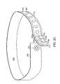
- FIG. 3Ashows a perspective view of an RFID bracelet according to the principals of the present invention
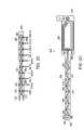
- FIG. 3Bshows a plan view of the bracelet of FIG. 3A ;
- FIG. 3Cshows a detailed view of the serpentine path followed by the conductive loop portions in the embodiment of of FIGS. 3A and 3B ;
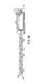
- FIG. 3Dshows a plan view of an embodiment of the invention where an RFID transducer chip is located distal from an antenna element.
- passive radio frequency identification (RFID) braceletsinclude circuits containing an antenna and other circuitry that responds to an RF interrogation signal.
- a transponderIn response to the RF interrogation signal, a transponder emits an RF signal representative of information pre-stored or pre-programmed into the transponder.
- the informationcould include a serial number, the date the bracelet is issued, the date the bracelet expires and will not longer be usable for access, the age status of the wearer, and/or whether the bracelet can be used for purchasing goods or services. Any other desired information, depending on the context in which the bracelet is to be used, may be pre-stored or pre-programmed in the transponder.
- Information stored on the transponder chipmay also be used to access information stored in a database.
- the transponderis electrically connected to and derives power from the antenna.
- the antennais typically formed as a wire coil.
- a connectionis made between the antenna and the transponder in the form of a continuous electrically conductive loop that extends around the wristband. Severance of any portion of the circuit will thus render the bracelet inoperable. Consideration should be given to the distance between the sections of the loop antenna that form the conductive loop in order to minimize inductance that can lead to possible interference with operation of the transponder and/or antenna.
- FIG. 1Ais a general illustration of a Radio Frequency Identification (RFID) bracelet 100 according to the prior art.
- the bracelet 100is generally an elongated band 110 with opposite ends 112 , 114 that can be brought together and fastened to form a closed loop.
- the band 110includes a plurality of adjustment holes 116 , a locking mechanism 118 , a radio frequency identification (RFID) transponder circuit 120 , and a tamper wire 122 .
- RFIDradio frequency identification
- the RFID circuit 120is electrically coupled to a tamper wire 122 which runs about the periphery of the band 110 .
- the RFID circuit 120will be rendered inoperative and the bracelet 110 rendered unusable if the tamper wire 122 is broken or severed.
- the locking mechanism 118is a mechanical non-reusable tamper-resistant locking mechanism.
- the locking mechanism 118can be a barbed peg 124 and locking hole 126 in a flap 128 .
- the locking mechanism 118is used to fasten the opposite ends 112 , 114 together under the flap 128 to form the closed loop as will be explained in more detail below.
- the adjustment holes 116are used to adjust the bracelet 100 to conform to body parts of different circumferences, e.g. a wrist or an ankle.
- ends 112 , 114 of the band 110are brought together, the barbed peg 124 is inserted through a selected hole 116 as required for a snug fit.
- the flap 128is then folded along an imaginary line 130 and the barbed peg 124 is then passed through the locking hole 126 .
- the barbed peg 124is shaped to resist removal from the locking hole 126 without also destroying the locking mechanism 118 and rendering it incapable of being refastened.
- this designis easily tampered with (defeated) to allow reuse of the band 110 .
- a simple slit (cut) 132can be made by slicing the band 110 material between the adjustment holes 116 without breaking or severing the tamper wire 122 , after which the circumference of the band 110 can be expanded to a size greater than the circumference of the body part to which the band is attached. The band 110 can then be slid over the body part and removed from the wearer, at which time the band 110 can be given or sold to an unauthorized user.
- FIGS. 2A–2Cillustrate an alternative way to defeat an RFID bracelet 200 of the prior art.
- the bracelet 200connects in similar fashion as explained above. That is, when ends 212 , 214 of the band 210 are brought together, a barbed peg 224 is inserted through a selected adjustment hole 216 as required for a snug fit. A flap 228 is then folded, as described above, and the barbed peg 224 is then passed through a locking hole 226 . The barbed peg 224 is shaped to resist removal from the locking hole 226 . (Please note that the flap is not shown in FIG. 2B for the sake of clarity).
- this designcan also be easily defeated by taking cutting instrument and cutting a slit 252 a between adjustment holes 216 a and 216 b without also cutting a tamper wire 222 .
- the slit 252 acreates a substantially enlarged space 254 a through which locking peg 224 can be slid.
- the space 254 a provided between adjustment holes 216 a and 216 b and slit 252 aenables locking peg 226 to be slid through the band material 210 .
- the processis similar to that used to unfasten a button on a dress shirt.
- An additional slit 252 bcan be made between adjustment holes 216 b and 216 c to provide an additional space 254 b for removing the locking hole 226 .
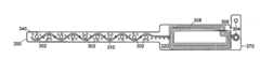
- FIGS. 3A–3Cillustrate a band 300 that prevents the aforementioned tampering.
- the band 300includes a plurality of adjustment holes 302 , a locking mechanism 304 , a radio frequency identification (RFID) transponder chip 306 , and an antenna element 308 .
- the antenna element 308is coupled to a conductive loop 310 that is configured on two or more electrically isolated layers of the band 300 , save for at least one electrical connection made preferably by a conductive hole or “via” 340 located at a distal end 350 of the band 300 .
- the conductive loop (traces) 310weave around adjustment holes 302 in a serpentine fashion as illustrated. As described below in further detail, this arrangement ensures that the RFID function is disabled even when the band 300 is cut in a manner similar to that explained above.
- the band 300is formed of a substrate 320 of suitable material such as plastic, polymer, nylon, paper, TyvekTM or other appropriate materials. (Tyvek is a trademark of E. I. du Pont de Nemours and Company for man-made materials.)
- the substrate 320has at least an upper surface 322 and a lower surface 324 .
- On the upper surface 322is formed an upper conductive portion 330 of the conductive loop 310 .
- a conductive hole or “via” 340is formed at a distal end 350 of the band 300 .
- the via 340provides electrical conductivity between the upper conductive portion 330 and lower conductive portion 332 of the conductive loop 310 .
- the distal end 340 of the band 300is the end farthest from the end of the band containing the RFID transponder chip 306 and antenna element 308 .
- conductive portions 330 and 332could also be formed on a wristband that has a multi-layer substrate 320 .
- the upper conductive portion 330is formed on one layer of the substrate 320 and the lower conductive portion 332 is formed on another layer of the substrate 320 .
- the antenna element 308 and conductive loop 310are preferably, but not necessarily, made from etched copper that is robust enough to withstand normal handling, but fragile enough that it will be broken if a user attempts to remove the bracelet.
- the conductive loop 310may be a printed conductive ink, a thin foil, or made by depositing other suitable electrically conductive material on one or more layers of the substrate 320 that will form an electrically continuous path but will break as a result of tampering.
- the conductive loop 310may also be formed from an insulated wire.
- Forming the conductive loop 310 with frangible zonesmay facilitate breakage of the conductor.
- the conductor forming loop 310will also be severed as band 300 is severed.
- the upper conductive portion 330 and lower conductive portion 332follow complimentary serpentine paths on their respective surfaces around the adjustment holes 302 .
- upper conductive portion 330first goes “above” a first hole 302 - 1 then passes between holes 302 - 1 and 302 - 2 , then traveling “below” hole 302 - 2 .
- itthen travels above hole 302 - 3 , and then likewise below hole 302 - 4 , continuing to travel above and then below any other remaining holes 302 in a serpentine path.
- the lower conductive portion 332(shown as the outline trace) follows a similar but complementary serpentine path around the holes 302 . Thus, starting at the distal end 350 , the lower conductive portion 332 first passes above hole 302 - 10 and then below hole 302 - 9 . From there, it travels above hole 302 - 8 and likewise until terminating at the near end 370 .
- the conductive portionsthus provide multiple points of overlap 333 , located between the holes 302 where the upper conductive portion 330 runs over the lower conductive portion 332 . However, the conductive portions are located on different surfaces 322 , 324 of the non-conductive substrate 320 . Thus, the two conductive portions 330 , 332 remain electrically isolated from one another.
- serpentine designis shown to be on upper and lower surfaces 322 , 324 of the substrate 320 , one skilled in the art will appreciate that the design can be accomplished on a multiple layer band, with the conductive traces located on different material layers, as long as the conductive loop 310 does not become short circuited at the points 333 where the serpentine paths overlap between holes 302 .
- the RFID chip 306can be placed distal from the antenna element 308 , as shown in FIG. 3D .
- This embodimentprovides an improvement over an arrangement where the RFID chip is located adjacent the coiled antenna section. In such a configuration, a simple cut of the band 300 anywhere away from the coiled antenna section 308 and/or adjacent RFID transponder chip 306 still permits the RFID transponder chip 306 and coiled antenna 308 to perform its RFID function.
- the band 300is arranged with the coiled antenna section 308 disposed on a surface of the band material 320 at the near end 370 , in the drawing shown as the right end of the band 300 .
- the RFID transponder chip 306On an opposite or distal end 350 of the band 300 is mounted the RFID transponder chip 306 .
- the conductive loop 310again runs in a serpentine path along the length of the band between the coiled antenna section 308 and the RFID transponder chip 306 , similar to the loop shown in FIGS. 3A–3C .
- conductive loop 310includes an upper conductive portion 330 and a lower conductive portion 332 formed on respective surfaces of the band.
- the upper conductive portion 330runs from a first point or node 380 of the coiled antenna 308 along an upper surface 322 of the band 300 , terminating at a first node 382 of the RFID transponder chip 306 .
- the lower conductive portion 332runs from a second node 384 of the RFID transponder chip 306 along a lower surface 324 of the band 300 back to a second node 386 of the coiled antenna 308 .
- the RFID transponder chip 306provides the electrical connection between the upper and lower surfaces 322 , 324 of the band 300 .
- This configurationalso provides protection against an attempt to repair a cut band as follows. Consider a situation where a cut is made on an imaginary line 390 perpendicular to a major axis of the band 300 . If one then attempts to repair the band 200 by rejoining the two pieces by simply laying a piece of tin foil between the two points 392 and 394 , the attempted repair merely results in shorting out the connection between the coiled antenna section 308 and the RFID transponder chip 306 , rather than re-establishing a connection between them.
Landscapes
- Engineering & Computer Science (AREA)
- Physics & Mathematics (AREA)
- General Physics & Mathematics (AREA)
- Computer Security & Cryptography (AREA)
- Computer Hardware Design (AREA)
- Microelectronics & Electronic Packaging (AREA)
- Theoretical Computer Science (AREA)
- Automation & Control Theory (AREA)
- Electromagnetism (AREA)
- General Engineering & Computer Science (AREA)
- Signal Processing (AREA)
- Health & Medical Sciences (AREA)
- Child & Adolescent Psychology (AREA)
- General Health & Medical Sciences (AREA)
- Business, Economics & Management (AREA)
- Emergency Management (AREA)
- Burglar Alarm Systems (AREA)
- Details Of Aerials (AREA)
Abstract
Description
Claims (18)
Priority Applications (4)
| Application Number | Priority Date | Filing Date | Title |
|---|---|---|---|
| US11/048,114US7119690B2 (en) | 2004-10-08 | 2005-02-01 | Identification band using serpentine paths to detect tampering |
| PCT/US2005/035366WO2006041746A2 (en) | 2004-10-08 | 2005-10-03 | Identification band using serpentine paths to detect tampering |
| US11/541,841US7579950B2 (en) | 2004-10-08 | 2006-10-02 | Identification band using serpentine paths to detect tampering |
| US12/583,688US20090315716A1 (en) | 2004-10-08 | 2009-08-25 | Identification band using serpentine paths to detect tampering |
Applications Claiming Priority (2)
| Application Number | Priority Date | Filing Date | Title |
|---|---|---|---|
| US61751804P | 2004-10-08 | 2004-10-08 | |
| US11/048,114US7119690B2 (en) | 2004-10-08 | 2005-02-01 | Identification band using serpentine paths to detect tampering |
Related Child Applications (1)
| Application Number | Title | Priority Date | Filing Date |
|---|---|---|---|
| US11/541,841ContinuationUS7579950B2 (en) | 2004-10-08 | 2006-10-02 | Identification band using serpentine paths to detect tampering |
Publications (2)
| Publication Number | Publication Date |
|---|---|
| US20060077060A1 US20060077060A1 (en) | 2006-04-13 |
| US7119690B2true US7119690B2 (en) | 2006-10-10 |
Family
ID=36144676
Family Applications (3)
| Application Number | Title | Priority Date | Filing Date |
|---|---|---|---|
| US11/048,114Expired - Fee RelatedUS7119690B2 (en) | 2004-10-08 | 2005-02-01 | Identification band using serpentine paths to detect tampering |
| US11/541,841Expired - Fee RelatedUS7579950B2 (en) | 2004-10-08 | 2006-10-02 | Identification band using serpentine paths to detect tampering |
| US12/583,688AbandonedUS20090315716A1 (en) | 2004-10-08 | 2009-08-25 | Identification band using serpentine paths to detect tampering |
Family Applications After (2)
| Application Number | Title | Priority Date | Filing Date |
|---|---|---|---|
| US11/541,841Expired - Fee RelatedUS7579950B2 (en) | 2004-10-08 | 2006-10-02 | Identification band using serpentine paths to detect tampering |
| US12/583,688AbandonedUS20090315716A1 (en) | 2004-10-08 | 2009-08-25 | Identification band using serpentine paths to detect tampering |
Country Status (2)
| Country | Link |
|---|---|
| US (3) | US7119690B2 (en) |
| WO (1) | WO2006041746A2 (en) |
Cited By (48)
| Publication number | Priority date | Publication date | Assignee | Title |
|---|---|---|---|---|
| US20050253725A1 (en)* | 2004-05-05 | 2005-11-17 | Trenstar, Inc. | Radio frequency identification tag |
| US20060152364A1 (en)* | 2004-12-30 | 2006-07-13 | Walton Charles A | RFID with field changeable identification |
| US20060238341A1 (en)* | 2005-04-20 | 2006-10-26 | International Business Machines Corporation | System and method of tamper detection |
| US20070011870A1 (en)* | 2005-07-18 | 2007-01-18 | Lerch John W | Method of manufacture of an identification wristband construction |
| USD542353S1 (en)* | 2005-10-28 | 2007-05-08 | Michael Henley | Tag |
| USD543589S1 (en)* | 2005-04-28 | 2007-05-29 | Michael Henley | Tag |
| US20070260491A1 (en)* | 2006-05-08 | 2007-11-08 | Pamela Palmer | System for delivery and monitoring of administration of controlled substances |
| US20070299687A1 (en)* | 2006-06-23 | 2007-12-27 | Pamela Palmer | Inpatient system for patient-controlled delivery of oral transmucosal medications dosed as needed |
| US20080164275A1 (en)* | 2007-01-05 | 2008-07-10 | Acelrx Pharmaceuticals, Inc. | Storage and dispensing devices for administration of oral transmucosal dosage forms |
| US20090045978A1 (en)* | 2005-10-24 | 2009-02-19 | Petratec International Ltd. | Devices and Methods Useful for Authorizing Purchases Associated with a Vehicle |
| US20090160622A1 (en)* | 2007-12-20 | 2009-06-25 | Frederic Bauchot | Dividing tagged items into subsets |
| US20090160603A1 (en)* | 2007-12-20 | 2009-06-25 | Frederic Bauchot | Locating rfid tags |
| US20090201154A1 (en)* | 2006-06-30 | 2009-08-13 | Frederic Bauchot | Apparatus for securing a land surveyor's mark based on the use of a radio frequency identifier tag |
| US20090289113A1 (en)* | 2005-10-24 | 2009-11-26 | Petratec International Ltd. | System and Method for Autorizing Purchases Associated with a Vehicle |
| US20090315679A1 (en)* | 2008-06-24 | 2009-12-24 | Frederic Bauchot | Location localization method and system |
| US20090315685A1 (en)* | 2008-06-20 | 2009-12-24 | International Business Machines Corporation | Methods and systems for rfid tag geographical location using beacon tags and listening tags |
| US20100012733A1 (en)* | 2005-11-29 | 2010-01-21 | Bartronics America, Inc. | Identification band using a conductive fastening for enhanced security and functionality |
| US20100102123A1 (en)* | 2008-10-28 | 2010-04-29 | First Data Corporation | Systems, Methods, and Apparatus for Facilitating Access to Medical Information |
| US20100102122A1 (en)* | 2008-10-28 | 2010-04-29 | First Data Corporation | Systems, Methods, and Apparatus to Facilitate Locating a User of a Transaction Device |
| US20100102131A1 (en)* | 2008-10-28 | 2010-04-29 | First Data Corporation | Systems and Methods for Disabling a Contactless Transaction Device |
| US20100114773A1 (en)* | 2008-10-31 | 2010-05-06 | First Data Corporation | Systems, Methods, And Apparatus For Using A Contactless Transaction Device Reader With A Computing System |
| US20100141455A1 (en)* | 2006-12-18 | 2010-06-10 | Paolo Stefanelli | Anti-theft device |
| US20100141403A1 (en)* | 2007-01-25 | 2010-06-10 | Petratec International Ltd. | Devices and methods useful for authorizing purchases associated with a vehicle |
| USRE41822E1 (en)* | 2005-04-28 | 2010-10-19 | Michael Henley | Tag |
| US20100273543A1 (en)* | 2007-03-13 | 2010-10-28 | Petratec International Ltd | Antenna assembly for service station |
| US20110043339A1 (en)* | 2009-08-19 | 2011-02-24 | Intelleflex Corporation | RF device with tamper detection |
| US20110079054A1 (en)* | 2009-10-02 | 2011-04-07 | Stanton Concepts Inc. | Dual Custody Privacy Padlock |
| US8028450B2 (en) | 2008-07-31 | 2011-10-04 | Typenex Medical, Llc | Recipient verification systems and methods of use including recipient identification |
| US20110248853A1 (en)* | 2010-04-07 | 2011-10-13 | Securealert, Inc. | Tracking device incorporating enhanced security mounting strap |
| US8231900B2 (en) | 2006-01-06 | 2012-07-31 | Acelrx Pharmaceutical, Inc. | Small-volume oral transmucosal dosage |
| US8252328B2 (en) | 2006-01-06 | 2012-08-28 | Acelrx Pharmaceuticals, Inc. | Bioadhesive drug formulations for oral transmucosal delivery |
| US8252329B2 (en) | 2007-01-05 | 2012-08-28 | Acelrx Pharmaceuticals, Inc. | Bioadhesive drug formulations for oral transmucosal delivery |
| US8357114B2 (en) | 2006-01-06 | 2013-01-22 | Acelrx Pharmaceuticals, Inc. | Drug dispensing device with flexible push rod |
| US8535714B2 (en) | 2006-01-06 | 2013-09-17 | Acelrx Pharmaceuticals, Inc. | Small volume oral transmucosal dosage forms containing sufentanil for treatment of pain |
| US8585852B2 (en) | 1999-06-16 | 2013-11-19 | Vanguard Identification Systems, Inc. | Methods of making printed planar radio frequency identification elements |
| US8636220B2 (en) | 2006-12-29 | 2014-01-28 | Vanguard Identification Systems, Inc. | Printed planar RFID element wristbands and like personal identification devices |
| US8654018B2 (en) | 2005-04-06 | 2014-02-18 | Vanguard Identificaiton Systems, Inc. | Printed planar RFID element wristbands and like personal identification devices |
| US8665069B2 (en) | 2007-10-19 | 2014-03-04 | Petratec International Ltd. | RFID tag especially for use near conductive objects |
| US8753308B2 (en) | 2006-01-06 | 2014-06-17 | Acelrx Pharmaceuticals, Inc. | Methods for administering small volume oral transmucosal dosage forms using a dispensing device |
| US8865743B2 (en) | 2006-01-06 | 2014-10-21 | Acelrx Pharmaceuticals, Inc. | Small volume oral transmucosal dosage forms containing sufentanil for treatment of pain |
| US8945592B2 (en) | 2008-11-21 | 2015-02-03 | Acelrx Pharmaceuticals, Inc. | Sufentanil solid dosage forms comprising oxygen scavengers and methods of using the same |
| US9289583B2 (en) | 2006-01-06 | 2016-03-22 | Acelrx Pharmaceuticals, Inc. | Methods for administering small volume oral transmucosal dosage forms using a dispensing device |
| US20160253889A1 (en)* | 2015-02-28 | 2016-09-01 | Kris Keyton | Home Incarceration Confirmation System |
| USD772984S1 (en)* | 2014-09-15 | 2016-11-29 | Precision Dynamics Corporation | Wristband with a detachable flag label |
| USD803318S1 (en)* | 2014-07-14 | 2017-11-21 | Precision Dynamics Corporation | Barcoded bloodband with adjacent labels |
| US10896751B2 (en) | 2009-03-18 | 2021-01-19 | Acelrx Pharmaceuticals, Inc. | Storage and dispensing devices for administration of oral transmucosal dosage forms |
| US11058856B2 (en) | 2014-12-23 | 2021-07-13 | Acelrx Pharmaceuticals, Inc. | Systems, devices and methods for dispensing oral transmucosal dosage forms |
| US11328199B2 (en)* | 2013-02-26 | 2022-05-10 | Quake Global, Inc. | Radio-frequency identification wristband with surface acoustic wave sensor |
Families Citing this family (27)
| Publication number | Priority date | Publication date | Assignee | Title |
|---|---|---|---|---|
| WO2007056557A1 (en)* | 2005-11-08 | 2007-05-18 | North Carolina State University | Methods and devices for providing flexible electronics |
| KR100769347B1 (en) | 2007-02-06 | 2007-10-24 | 권재순 | Tag for band |
| US20080290176A1 (en)* | 2007-05-22 | 2008-11-27 | Precision Dynamics Corporation | Methods and devices with a circuit for carrying information on a host |
| US8128000B2 (en)* | 2009-09-25 | 2012-03-06 | Avery Dennison Corporation | Method, system and apparatus for manufacturing a radio frequency identification device |
| MX2012012444A (en) | 2010-04-30 | 2013-03-18 | Spm Flow Control Inc | MACHINES, SYSTEMS, METHODS IMPLEMENTED IN COMPUTERS, AND PROGRAM PRODUCTS IN COMPUTERS TO TEST AND CERTIFY PETROLEUM AND GAS EQUIPMENT. |
| KR101149364B1 (en) | 2010-09-13 | 2012-05-30 | (주)크리노 | Fish tag |
| WO2012066463A1 (en)* | 2010-11-15 | 2012-05-24 | Orpak Systems Ltd. | Device for automated fuel delivery authorization and method for installation thereof |
| GB2487961A (en)* | 2011-02-10 | 2012-08-15 | Id3As Company Ltd | Tamper resistant identification band |
| US9064391B2 (en)* | 2011-12-20 | 2015-06-23 | Techip International Limited | Tamper-alert resistant bands for human limbs and associated monitoring systems and methods |
| CA2773150C (en)* | 2012-03-30 | 2021-10-26 | Guard Rfid Solutions Inc. | Anti-tamper conductive plastic band for rfid tag |
| USD713825S1 (en) | 2012-05-09 | 2014-09-23 | S.P.M. Flow Control, Inc. | Electronic device holder |
| EP2855836B1 (en) | 2012-05-25 | 2019-03-06 | S.P.M. Flow Control, Inc. | Apparatus and methods for evaluating systems associated with wellheads |
| US20150109106A1 (en)* | 2013-10-20 | 2015-04-23 | VenGo, LLC | System for Holding an RFID within a Slotted Wearable Device |
| US20150109107A1 (en)* | 2013-10-20 | 2015-04-23 | VenGo, LLC | System for Holding Multiple RFIDs in a Wearable Device |
| US9460612B2 (en) | 2014-05-01 | 2016-10-04 | Techip International Limited | Tamper-alert and tamper-resistant band |
| WO2016019039A1 (en) | 2014-07-30 | 2016-02-04 | S.P.M. Flow Control, Inc. | Band with rfid chip holder and identifying component |
| USD750516S1 (en) | 2014-09-26 | 2016-03-01 | S.P.M. Flow Control, Inc. | Electronic device holder |
| WO2016187503A1 (en) | 2015-05-21 | 2016-11-24 | Texas Nameplate Company, Inc. | Method and system for securing a tracking device to a component |
| KR200482406Y1 (en)* | 2015-06-05 | 2017-01-20 | 국지명 | Anti-tampering wristband using rfid-tag |
| US10102471B2 (en) | 2015-08-14 | 2018-10-16 | S.P.M. Flow Control, Inc. | Carrier and band assembly for identifying and managing a component of a system associated with a wellhead |
| WO2018067876A2 (en) | 2016-10-05 | 2018-04-12 | Board Of Regents, The University Of Texas System | Nanopulse light therapy |
| KR200485047Y1 (en)* | 2016-12-29 | 2017-11-22 | 국지명 | Anti-tampering wristband using rfid-tag |
| AU2018337962B2 (en)* | 2017-09-20 | 2024-02-01 | Avery Dennison Retail Information Services Llc | RFID wristband |
| US11151542B2 (en)* | 2019-05-07 | 2021-10-19 | Paypal, Inc. | Wearable payment device |
| US11393319B1 (en) | 2019-07-29 | 2022-07-19 | REMI Device Company | Personal tracking and communication system and method |
| US11288561B2 (en)* | 2019-11-07 | 2022-03-29 | CoreKinect LLC | Methods and apparatus for a security sticker anti-tampering system |
| US12175319B1 (en)* | 2023-08-09 | 2024-12-24 | Zebra Technologies Corporation | Wristbands having RFID circuits with enhanced readability |
Citations (24)
| Publication number | Priority date | Publication date | Assignee | Title |
|---|---|---|---|---|
| US5032823A (en)* | 1988-05-27 | 1991-07-16 | Digital Products Corporation | Secure personnel monitoring system |
| US5448846A (en) | 1992-04-09 | 1995-09-12 | Precision Dynamics Corporation | Identification device for machine imprinting |
| US5457906A (en) | 1992-11-19 | 1995-10-17 | Precision Dynamics Corporation | Adhesive closure for identification band and method |
| US5627720A (en) | 1995-08-11 | 1997-05-06 | Lewis; Keith A. | Power distribution box with surge suppressor |
| US5627520A (en)* | 1995-07-10 | 1997-05-06 | Protell Systems International, Inc. | Tamper detect monitoring device |
| US5883576A (en) | 1998-01-14 | 1999-03-16 | De La Huerga; Carlos | Identification bracelet with electronics information |
| US5973598A (en)* | 1997-09-11 | 1999-10-26 | Precision Dynamics Corporation | Radio frequency identification tag on flexible substrate |
| US5973600A (en) | 1997-09-11 | 1999-10-26 | Precision Dynamics Corporation | Laminated radio frequency identification device |
| US5977877A (en) | 1998-05-18 | 1999-11-02 | Instantel Inc. | Multiple conductor security tag |
| US5979941A (en) | 1996-11-19 | 1999-11-09 | Mosher, Jr.; Walter W. | Linkage identification system |
| US6043746A (en) | 1999-02-17 | 2000-03-28 | Microchip Technology Incorporated | Radio frequency identification (RFID) security tag for merchandise and method therefor |
| US6050622A (en)* | 1991-12-19 | 2000-04-18 | Gustafson; Ake | Safety sealing device |
| US6211790B1 (en)* | 1999-05-19 | 2001-04-03 | Elpas North America, Inc. | Infant and parent matching and security system and method of matching infant and parent |
| US6236319B1 (en)* | 1998-07-31 | 2001-05-22 | Beryl E. Pitzer | Personal monitoring system |
| US6255951B1 (en) | 1996-12-20 | 2001-07-03 | Carlos De La Huerga | Electronic identification bracelet |
| US6346886B1 (en) | 1996-12-20 | 2002-02-12 | Carlos De La Huerga | Electronic identification apparatus |
| US20020067264A1 (en) | 2000-03-15 | 2002-06-06 | Soehnlen John Pius | Tamper Evident Radio Frequency Identification System And Package |
| US20020084904A1 (en) | 1996-12-20 | 2002-07-04 | Carlos De La Huerga | Electronic identification apparatus |
| US6421013B1 (en) | 1999-10-04 | 2002-07-16 | Amerasia International Technology, Inc. | Tamper-resistant wireless article including an antenna |
| US20030075608A1 (en) | 2000-03-21 | 2003-04-24 | Atherton Peter S | Tamper indicating radio frequency identification label |
| US20030173408A1 (en)* | 2002-03-18 | 2003-09-18 | Precision Dynamics Corporation | Enhanced identification appliance |
| US20040066296A1 (en) | 2001-11-15 | 2004-04-08 | Atherton Peter S. | Tamper indicating radio frequency identification label with tracking capability |
| US6782648B1 (en) | 1992-11-09 | 2004-08-31 | Precision Dynamics Corporation | Wristband having exposed adhesive fastener |
| US20060097870A1 (en)* | 2004-11-02 | 2006-05-11 | Sang Hoon Choi | Radio frquency identification tag apparatus for tire in radio freqeuncy identification system |
Family Cites Families (4)
| Publication number | Priority date | Publication date | Assignee | Title |
|---|---|---|---|---|
| US5128686A (en)* | 1989-01-23 | 1992-07-07 | Motorola, Inc. | Reactance buffered loop antenna and method for making the same |
| US5694139A (en)* | 1994-06-28 | 1997-12-02 | Sony Corporation | Short-distance communication antenna and methods of manufacturing and using the short-distance communication antenna |
| US5504474A (en)* | 1994-07-18 | 1996-04-02 | Elmo Tech Ltd. | Tag for electronic personnel monitoring |
| US7084764B2 (en)* | 2004-04-15 | 2006-08-01 | Secure Care Products, Inc. | System and method for monitoring location of an object |
- 2005
- 2005-02-01USUS11/048,114patent/US7119690B2/ennot_activeExpired - Fee Related
- 2005-10-03WOPCT/US2005/035366patent/WO2006041746A2/enactiveApplication Filing
- 2006
- 2006-10-02USUS11/541,841patent/US7579950B2/ennot_activeExpired - Fee Related
- 2009
- 2009-08-25USUS12/583,688patent/US20090315716A1/ennot_activeAbandoned
Patent Citations (25)
| Publication number | Priority date | Publication date | Assignee | Title |
|---|---|---|---|---|
| US5032823A (en)* | 1988-05-27 | 1991-07-16 | Digital Products Corporation | Secure personnel monitoring system |
| US6050622A (en)* | 1991-12-19 | 2000-04-18 | Gustafson; Ake | Safety sealing device |
| US5448846A (en) | 1992-04-09 | 1995-09-12 | Precision Dynamics Corporation | Identification device for machine imprinting |
| US6782648B1 (en) | 1992-11-09 | 2004-08-31 | Precision Dynamics Corporation | Wristband having exposed adhesive fastener |
| US5457906A (en) | 1992-11-19 | 1995-10-17 | Precision Dynamics Corporation | Adhesive closure for identification band and method |
| US5627520A (en)* | 1995-07-10 | 1997-05-06 | Protell Systems International, Inc. | Tamper detect monitoring device |
| US5627720A (en) | 1995-08-11 | 1997-05-06 | Lewis; Keith A. | Power distribution box with surge suppressor |
| US5979941A (en) | 1996-11-19 | 1999-11-09 | Mosher, Jr.; Walter W. | Linkage identification system |
| US20020084904A1 (en) | 1996-12-20 | 2002-07-04 | Carlos De La Huerga | Electronic identification apparatus |
| US6255951B1 (en) | 1996-12-20 | 2001-07-03 | Carlos De La Huerga | Electronic identification bracelet |
| US6346886B1 (en) | 1996-12-20 | 2002-02-12 | Carlos De La Huerga | Electronic identification apparatus |
| US5973598A (en)* | 1997-09-11 | 1999-10-26 | Precision Dynamics Corporation | Radio frequency identification tag on flexible substrate |
| US5973600A (en) | 1997-09-11 | 1999-10-26 | Precision Dynamics Corporation | Laminated radio frequency identification device |
| US5883576A (en) | 1998-01-14 | 1999-03-16 | De La Huerga; Carlos | Identification bracelet with electronics information |
| US5977877A (en) | 1998-05-18 | 1999-11-02 | Instantel Inc. | Multiple conductor security tag |
| US6236319B1 (en)* | 1998-07-31 | 2001-05-22 | Beryl E. Pitzer | Personal monitoring system |
| US6043746A (en) | 1999-02-17 | 2000-03-28 | Microchip Technology Incorporated | Radio frequency identification (RFID) security tag for merchandise and method therefor |
| US6211790B1 (en)* | 1999-05-19 | 2001-04-03 | Elpas North America, Inc. | Infant and parent matching and security system and method of matching infant and parent |
| US6421013B1 (en) | 1999-10-04 | 2002-07-16 | Amerasia International Technology, Inc. | Tamper-resistant wireless article including an antenna |
| US20020067264A1 (en) | 2000-03-15 | 2002-06-06 | Soehnlen John Pius | Tamper Evident Radio Frequency Identification System And Package |
| US20030075608A1 (en) | 2000-03-21 | 2003-04-24 | Atherton Peter S | Tamper indicating radio frequency identification label |
| US6888509B2 (en)* | 2000-03-21 | 2005-05-03 | Mikoh Corporation | Tamper indicating radio frequency identification label |
| US20040066296A1 (en) | 2001-11-15 | 2004-04-08 | Atherton Peter S. | Tamper indicating radio frequency identification label with tracking capability |
| US20030173408A1 (en)* | 2002-03-18 | 2003-09-18 | Precision Dynamics Corporation | Enhanced identification appliance |
| US20060097870A1 (en)* | 2004-11-02 | 2006-05-11 | Sang Hoon Choi | Radio frquency identification tag apparatus for tire in radio freqeuncy identification system |
Cited By (86)
| Publication number | Priority date | Publication date | Assignee | Title |
|---|---|---|---|---|
| US8585852B2 (en) | 1999-06-16 | 2013-11-19 | Vanguard Identification Systems, Inc. | Methods of making printed planar radio frequency identification elements |
| US20050253725A1 (en)* | 2004-05-05 | 2005-11-17 | Trenstar, Inc. | Radio frequency identification tag |
| US20060152364A1 (en)* | 2004-12-30 | 2006-07-13 | Walton Charles A | RFID with field changeable identification |
| US8654018B2 (en) | 2005-04-06 | 2014-02-18 | Vanguard Identificaiton Systems, Inc. | Printed planar RFID element wristbands and like personal identification devices |
| US20060238341A1 (en)* | 2005-04-20 | 2006-10-26 | International Business Machines Corporation | System and method of tamper detection |
| US7382262B2 (en)* | 2005-04-20 | 2008-06-03 | International Business Machines Corporation | System and method of tamper detection |
| US7791484B2 (en) | 2005-04-20 | 2010-09-07 | International Business Machines Corporation | System for tamper detection |
| US20080211676A1 (en)* | 2005-04-20 | 2008-09-04 | Francois Commagnac | System for tamper detection |
| USRE41822E1 (en)* | 2005-04-28 | 2010-10-19 | Michael Henley | Tag |
| USD543589S1 (en)* | 2005-04-28 | 2007-05-29 | Michael Henley | Tag |
| US20070011870A1 (en)* | 2005-07-18 | 2007-01-18 | Lerch John W | Method of manufacture of an identification wristband construction |
| US7562445B2 (en)* | 2005-07-18 | 2009-07-21 | Bartronics America, Inc. | Method of manufacture of an identification wristband construction |
| US7907058B2 (en)* | 2005-10-24 | 2011-03-15 | Petratec International Ltd. | Devices and methods useful for authorizing purchases associated with a vehicle |
| US20090045978A1 (en)* | 2005-10-24 | 2009-02-19 | Petratec International Ltd. | Devices and Methods Useful for Authorizing Purchases Associated with a Vehicle |
| US8292168B2 (en) | 2005-10-24 | 2012-10-23 | Petratec International Ltd. | System and method for authorizing purchases associated with a vehicle |
| US20090289113A1 (en)* | 2005-10-24 | 2009-11-26 | Petratec International Ltd. | System and Method for Autorizing Purchases Associated with a Vehicle |
| USD542353S1 (en)* | 2005-10-28 | 2007-05-08 | Michael Henley | Tag |
| US20100012733A1 (en)* | 2005-11-29 | 2010-01-21 | Bartronics America, Inc. | Identification band using a conductive fastening for enhanced security and functionality |
| US10245228B2 (en) | 2006-01-06 | 2019-04-02 | Acelrx Pharmaceuticals, Inc. | Small volume oral transmucosal dosage forms containing sufentanil for treatment of pain |
| US8753308B2 (en) | 2006-01-06 | 2014-06-17 | Acelrx Pharmaceuticals, Inc. | Methods for administering small volume oral transmucosal dosage forms using a dispensing device |
| US10709881B2 (en) | 2006-01-06 | 2020-07-14 | Acelrx Pharmaceuticals, Inc. | Apparatus for administering small volume oral transmucosal dosage forms |
| US9289583B2 (en) | 2006-01-06 | 2016-03-22 | Acelrx Pharmaceuticals, Inc. | Methods for administering small volume oral transmucosal dosage forms using a dispensing device |
| US10507180B2 (en) | 2006-01-06 | 2019-12-17 | Acelrx Pharmaceuticals, Inc. | Small volume oral transmucosal dosage forms containing sufentanil for treatment of pain |
| US10342762B2 (en) | 2006-01-06 | 2019-07-09 | Acelrx Pharmaceuticals, Inc. | Small-volume oral transmucosal dosage forms |
| US8357114B2 (en) | 2006-01-06 | 2013-01-22 | Acelrx Pharmaceuticals, Inc. | Drug dispensing device with flexible push rod |
| US8905964B2 (en) | 2006-01-06 | 2014-12-09 | Acelrx Pharmaceuticals, Inc. | Drug storage and dispensing devices and systems comprising the same |
| US9642996B2 (en) | 2006-01-06 | 2017-05-09 | Acelrx Pharmaceuticals, Inc. | Methods and apparatus for administering small volume oral transmucosal dosage forms |
| US8865743B2 (en) | 2006-01-06 | 2014-10-21 | Acelrx Pharmaceuticals, Inc. | Small volume oral transmucosal dosage forms containing sufentanil for treatment of pain |
| US8865211B2 (en) | 2006-01-06 | 2014-10-21 | Acelrx Pharmaceuticals, Inc. | Bioadhesive drug formulations for oral transmucosal delivery |
| US8778393B2 (en) | 2006-01-06 | 2014-07-15 | Acelrx Pharmaceuticals, Inc. | Small volume oral transmucosal dosage forms containing sufentanil for treatment of pain |
| US8778394B2 (en) | 2006-01-06 | 2014-07-15 | Acelrx Pharmaceuticals, Inc. | Small-volume oral transmucosal dosage forms |
| US8499966B2 (en) | 2006-01-06 | 2013-08-06 | Acelrx Pharmaceuticals, Inc. | Method of moving a delivery member of a dispensing device for administration of oral transmucosal dosage forms |
| US8535714B2 (en) | 2006-01-06 | 2013-09-17 | Acelrx Pharmaceuticals, Inc. | Small volume oral transmucosal dosage forms containing sufentanil for treatment of pain |
| US9744129B2 (en) | 2006-01-06 | 2017-08-29 | Acelrx Pharmaceuticals, Inc. | Small volume oral transmucosal dosage forms containing sufentanil for treatment of pain |
| US9320710B2 (en) | 2006-01-06 | 2016-04-26 | Acelrx Pharmaceuticals, Inc. | Small volume oral transmucosal dosage forms containing sufentanil for treatment of pain |
| US8252328B2 (en) | 2006-01-06 | 2012-08-28 | Acelrx Pharmaceuticals, Inc. | Bioadhesive drug formulations for oral transmucosal delivery |
| US8231900B2 (en) | 2006-01-06 | 2012-07-31 | Acelrx Pharmaceutical, Inc. | Small-volume oral transmucosal dosage |
| US20070260491A1 (en)* | 2006-05-08 | 2007-11-08 | Pamela Palmer | System for delivery and monitoring of administration of controlled substances |
| US20070299687A1 (en)* | 2006-06-23 | 2007-12-27 | Pamela Palmer | Inpatient system for patient-controlled delivery of oral transmucosal medications dosed as needed |
| US8610581B2 (en) | 2006-06-30 | 2013-12-17 | International Business Machines Corporation | Securing a land surveyor's mark based on use of a radio frequency identifier tag |
| US8289167B2 (en) | 2006-06-30 | 2012-10-16 | International Business Machines Corporation | Apparatus for securing a land surveyor'S mark based on the use of a radio frequency identifier tag |
| US20090201154A1 (en)* | 2006-06-30 | 2009-08-13 | Frederic Bauchot | Apparatus for securing a land surveyor's mark based on the use of a radio frequency identifier tag |
| US20100141455A1 (en)* | 2006-12-18 | 2010-06-10 | Paolo Stefanelli | Anti-theft device |
| US8636220B2 (en) | 2006-12-29 | 2014-01-28 | Vanguard Identification Systems, Inc. | Printed planar RFID element wristbands and like personal identification devices |
| US9066847B2 (en) | 2007-01-05 | 2015-06-30 | Aceirx Pharmaceuticals, Inc. | Storage and dispensing devices for administration of oral transmucosal dosage forms |
| US20080164275A1 (en)* | 2007-01-05 | 2008-07-10 | Acelrx Pharmaceuticals, Inc. | Storage and dispensing devices for administration of oral transmucosal dosage forms |
| US8252329B2 (en) | 2007-01-05 | 2012-08-28 | Acelrx Pharmaceuticals, Inc. | Bioadhesive drug formulations for oral transmucosal delivery |
| US20100141403A1 (en)* | 2007-01-25 | 2010-06-10 | Petratec International Ltd. | Devices and methods useful for authorizing purchases associated with a vehicle |
| US20100273543A1 (en)* | 2007-03-13 | 2010-10-28 | Petratec International Ltd | Antenna assembly for service station |
| US8364094B2 (en) | 2007-03-13 | 2013-01-29 | Petratec International Ltd. | Antenna assembly for service station |
| US8665069B2 (en) | 2007-10-19 | 2014-03-04 | Petratec International Ltd. | RFID tag especially for use near conductive objects |
| US20090160622A1 (en)* | 2007-12-20 | 2009-06-25 | Frederic Bauchot | Dividing tagged items into subsets |
| US8289129B2 (en) | 2007-12-20 | 2012-10-16 | International Business Machines Corporation | Locating RFID tags |
| US20090160603A1 (en)* | 2007-12-20 | 2009-06-25 | Frederic Bauchot | Locating rfid tags |
| US9659194B2 (en) | 2007-12-20 | 2017-05-23 | International Business Machines Corporation | Dividing tagged items into subsets |
| US9946900B2 (en) | 2007-12-20 | 2018-04-17 | International Business Machines Corporation | Dividing tagged items into subsets |
| US20090315685A1 (en)* | 2008-06-20 | 2009-12-24 | International Business Machines Corporation | Methods and systems for rfid tag geographical location using beacon tags and listening tags |
| US8228171B2 (en) | 2008-06-20 | 2012-07-24 | International Business Machines Corporation | Methods and systems for RFID tag geographical location using beacon tags and listening tags |
| US8207820B2 (en) | 2008-06-24 | 2012-06-26 | International Business Machines Corporation | Location localization method and system |
| US8362877B2 (en) | 2008-06-24 | 2013-01-29 | International Business Machines Corporation | Location localization |
| US20090315679A1 (en)* | 2008-06-24 | 2009-12-24 | Frederic Bauchot | Location localization method and system |
| US8028450B2 (en) | 2008-07-31 | 2011-10-04 | Typenex Medical, Llc | Recipient verification systems and methods of use including recipient identification |
| US20100102122A1 (en)* | 2008-10-28 | 2010-04-29 | First Data Corporation | Systems, Methods, and Apparatus to Facilitate Locating a User of a Transaction Device |
| US8550361B2 (en) | 2008-10-28 | 2013-10-08 | First Data Corporation | Systems, methods, and apparatus to facilitate locating a user of a transaction device |
| US20100102123A1 (en)* | 2008-10-28 | 2010-04-29 | First Data Corporation | Systems, Methods, and Apparatus for Facilitating Access to Medical Information |
| US20100102131A1 (en)* | 2008-10-28 | 2010-04-29 | First Data Corporation | Systems and Methods for Disabling a Contactless Transaction Device |
| US10803515B2 (en) | 2008-10-31 | 2020-10-13 | First Data Corporation | Systems, methods, and apparatus for using a contactless transaction device reader with a computing system |
| US20100114773A1 (en)* | 2008-10-31 | 2010-05-06 | First Data Corporation | Systems, Methods, And Apparatus For Using A Contactless Transaction Device Reader With A Computing System |
| US8945592B2 (en) | 2008-11-21 | 2015-02-03 | Acelrx Pharmaceuticals, Inc. | Sufentanil solid dosage forms comprising oxygen scavengers and methods of using the same |
| US12033733B2 (en) | 2009-03-18 | 2024-07-09 | Vertical Pharmaceuticals, Llc | Storage and dispensing devices for administration of oral transmucosal dosage forms |
| US11676691B2 (en) | 2009-03-18 | 2023-06-13 | Vertical Pharmaceuticals, Llc | Storage and dispensing devices for administration of oral transmucosal dosage forms |
| US10896751B2 (en) | 2009-03-18 | 2021-01-19 | Acelrx Pharmaceuticals, Inc. | Storage and dispensing devices for administration of oral transmucosal dosage forms |
| US20110043339A1 (en)* | 2009-08-19 | 2011-02-24 | Intelleflex Corporation | RF device with tamper detection |
| US9082057B2 (en)* | 2009-08-19 | 2015-07-14 | Intelleflex Corporation | RF device with tamper detection |
| US20110079054A1 (en)* | 2009-10-02 | 2011-04-07 | Stanton Concepts Inc. | Dual Custody Privacy Padlock |
| US8186187B2 (en) | 2009-10-02 | 2012-05-29 | Stanton Concepts, L.L.C. | Dual custody privacy padlock |
| US20110248853A1 (en)* | 2010-04-07 | 2011-10-13 | Securealert, Inc. | Tracking device incorporating enhanced security mounting strap |
| US8514070B2 (en)* | 2010-04-07 | 2013-08-20 | Securealert, Inc. | Tracking device incorporating enhanced security mounting strap |
| US9129504B2 (en) | 2010-04-07 | 2015-09-08 | Securealert, Inc. | Tracking device incorporating cuff with cut resistant materials |
| US11328199B2 (en)* | 2013-02-26 | 2022-05-10 | Quake Global, Inc. | Radio-frequency identification wristband with surface acoustic wave sensor |
| USD803318S1 (en)* | 2014-07-14 | 2017-11-21 | Precision Dynamics Corporation | Barcoded bloodband with adjacent labels |
| USD839962S1 (en) | 2014-09-15 | 2019-02-05 | Precision Dynamics Corporation | Wrist band with a detachable flag label |
| USD772984S1 (en)* | 2014-09-15 | 2016-11-29 | Precision Dynamics Corporation | Wristband with a detachable flag label |
| US11058856B2 (en) | 2014-12-23 | 2021-07-13 | Acelrx Pharmaceuticals, Inc. | Systems, devices and methods for dispensing oral transmucosal dosage forms |
| US9990831B2 (en)* | 2015-02-28 | 2018-06-05 | Kris Keyton | Home incarceration confirmation system |
| US20160253889A1 (en)* | 2015-02-28 | 2016-09-01 | Kris Keyton | Home Incarceration Confirmation System |
Also Published As
| Publication number | Publication date |
|---|---|
| WO2006041746A3 (en) | 2006-06-08 |
| US20090315716A1 (en) | 2009-12-24 |
| WO2006041746A2 (en) | 2006-04-20 |
| US20080048865A1 (en) | 2008-02-28 |
| US20060077060A1 (en) | 2006-04-13 |
| US7579950B2 (en) | 2009-08-25 |
Similar Documents
| Publication | Publication Date | Title |
|---|---|---|
| US7119690B2 (en) | Identification band using serpentine paths to detect tampering | |
| US7283054B2 (en) | Tamper-resistant RFID disabling apparatus and method of manufacturing | |
| US7168626B2 (en) | Identification band using shorting wire for enabling/disabling an RFID transponder contained thereon | |
| US7535356B2 (en) | Identification band using a conductive fastening for enhanced security and functionality | |
| US7316358B2 (en) | Identification band with adhesively attached coupling elements | |
| US7417541B2 (en) | Identification band with regions having electro-magnetically detectable regions | |
| US7562445B2 (en) | Method of manufacture of an identification wristband construction | |
| AU707649B2 (en) | Deactivateable security tag | |
| CN100388558C (en) | Microstrip antenna for an identification appliance | |
| US7286055B2 (en) | Tamper-resistant RFID disabling apparatus | |
| US7377447B2 (en) | Tuned radio frequency identification (RFID) circuit used as a security device for wristbands and package security | |
| US20080290176A1 (en) | Methods and devices with a circuit for carrying information on a host | |
| MXPA97001722A (en) | Safety label and fabricac method |
Legal Events
| Date | Code | Title | Description |
|---|---|---|---|
| AS | Assignment | Owner name:PROXIMITIES, INC., FLORIDA Free format text:ASSIGNMENT OF ASSIGNORS INTEREST;ASSIGNORS:LERCH, JOHN W.;GIRVIN, JOSHUA M.;NORAIR, JOHN P.;AND OTHERS;REEL/FRAME:016218/0913 Effective date:20050407 | |
| AS | Assignment | Owner name:FLOMENHOFT, MARK J., FLORIDA Free format text:SECURITY AGREEMENT;ASSIGNOR:PROXIMITIES, INC.;REEL/FRAME:018194/0507 Effective date:20060811 | |
| AS | Assignment | Owner name:PROXIMITIES, INC., FLORIDA Free format text:RELEASE OF SECURITY INTEREST;ASSIGNOR:FLOMENHOFT, MARK J.;REEL/FRAME:020487/0639 Effective date:20071228 Owner name:BARTRONICS AMERICA, INC., CALIFORNIA Free format text:ASSIGNMENT OF ASSIGNORS INTEREST;ASSIGNOR:PROXIMITIES, INC.;REEL/FRAME:020491/0600 Effective date:20080109 | |
| FEPP | Fee payment procedure | Free format text:PAYOR NUMBER ASSIGNED (ORIGINAL EVENT CODE: ASPN); ENTITY STATUS OF PATENT OWNER: LARGE ENTITY | |
| FPAY | Fee payment | Year of fee payment:4 | |
| AS | Assignment | Owner name:BARTRONICS HONG KONG LIMITED, HONG KONG Free format text:ASSIGNMENT OF ASSIGNORS INTEREST;ASSIGNOR:BARTRONICS AMERICA, INC.;REEL/FRAME:026043/0622 Effective date:20110302 | |
| REMI | Maintenance fee reminder mailed | ||
| LAPS | Lapse for failure to pay maintenance fees | ||
| STCH | Information on status: patent discontinuation | Free format text:PATENT EXPIRED DUE TO NONPAYMENT OF MAINTENANCE FEES UNDER 37 CFR 1.362 | |
| FP | Lapsed due to failure to pay maintenance fee | Effective date:20141010 |