US7119289B2 - Push button keypad and knob for motor vehicle control panel - Google Patents
Push button keypad and knob for motor vehicle control panelDownload PDFInfo
- Publication number
- US7119289B2 US7119289B2US10/938,175US93817504AUS7119289B2US 7119289 B2US7119289 B2US 7119289B2US 93817504 AUS93817504 AUS 93817504AUS 7119289 B2US7119289 B2US 7119289B2
- Authority
- US
- United States
- Prior art keywords
- button
- buttons
- keypad
- contactor
- base
- Prior art date
- Legal status (The legal status is an assumption and is not a legal conclusion. Google has not performed a legal analysis and makes no representation as to the accuracy of the status listed.)
- Expired - Lifetime
Links
- 230000000694effectsEffects0.000claimsabstractdescription14
- 238000006073displacement reactionMethods0.000claimsdescription12
- 239000000463materialSubstances0.000claimsdescription12
- 210000003813thumbAnatomy0.000claimsdescription6
- 238000001746injection mouldingMethods0.000claimsdescription2
- 230000002411adverseEffects0.000description1
- 238000000465mouldingMethods0.000description1
Images


Classifications
- H—ELECTRICITY
- H01—ELECTRIC ELEMENTS
- H01H—ELECTRIC SWITCHES; RELAYS; SELECTORS; EMERGENCY PROTECTIVE DEVICES
- H01H13/00—Switches having rectilinearly-movable operating part or parts adapted for pushing or pulling in one direction only, e.g. push-button switch
- H01H13/70—Switches having rectilinearly-movable operating part or parts adapted for pushing or pulling in one direction only, e.g. push-button switch having a plurality of operating members associated with different sets of contacts, e.g. keyboard
- H—ELECTRICITY
- H01—ELECTRIC ELEMENTS
- H01H—ELECTRIC SWITCHES; RELAYS; SELECTORS; EMERGENCY PROTECTIVE DEVICES
- H01H2221/00—Actuators
- H01H2221/074—One molded piece
- H—ELECTRICITY
- H01—ELECTRIC ELEMENTS
- H01H—ELECTRIC SWITCHES; RELAYS; SELECTORS; EMERGENCY PROTECTIVE DEVICES
- H01H2223/00—Casings
- H01H2223/002—Casings sealed
- H01H2223/004—Evacuation of penetrating liquid
Definitions
- the inventionrelates to a keypad provided with push-buttons and to a knob equipped with such a keypad, in particular for a motor vehicle control panel.
- buttonsare not linked together and are each provided with guidance and foolproofing means for preventing them from jamming. Moulding of the guidance and foolproofing means into the front of the control panel is often delicate, and the same is true of the guide ribs of the buttons associated therewith. This involves successive adjustments in the moulds which are therefore complex and expensive to produce. Moreover, each button has to be mounted the correct way upon assembly, and this takes a lot of time.
- buttonsthat are not guided, but these have to withstand a high return force which is harmful to the button and adversely affects the ease of use.
- the inventionproposes grouping the buttons together and positioning them in the keypad so as to facilitate use thereof without the need for foolproofing or guidance means.
- the object of the inventionis a keypad for a control panel, in particular for a motor vehicle instrument system, comprising a front provided with openings through which a number of push-buttons are placed, each positioned facing a contactor fixed to a card, in which the buttons are linked together at least in groups of two to form a unitary set and are placed with respect to one another on the keypad such that each button can be moved individually and pushing thereof causes solely actuation of the contactor assigned to said button, without any effect on the contactors of the other buttons.
- the present inventionalso relates to a knob provided with a keypad as defined above, the buttons of which are arranged around a central thumb wheel which can rotate, and also to a motor vehicle control panel equipped with such a keypad or with such a knob.
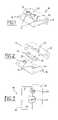
- FIG. 1shows a perspective view of a keypad comprising two buttons according to the invention
- FIG. 2shows an exploded perspective view of FIG. 1
- FIG. 3shows a front view of FIG. 1
- FIG. 4shows a sectional view of FIG. 1
- FIG. 5shows another perspective view in which one button of the keypad has been pushed
- FIG. 6shows a sectional view of FIG. 5
- FIG. 7shows a perspective view of a variant embodiment of the invention in which the keypad has three buttons
- FIG. 8shows a perspective view of a variant embodiment of the invention in which the keypad has four buttons
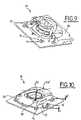
- FIG. 9shows a partially cut-away perspective view of FIG. 8 .
- FIG. 10shows another perspective view in which a button of the keypad of FIGS. 8 and 9 has been pushed.
- the keypad 10 of the present inventioncomprises a rigid base card 12 on which mechanical contactors 14 and light indicators 16 such as LEDs are mounted.
- Each contactor 14is associated with a button 20 mounted opposite it.
- the buttons 20are grouped into a unitary set 22 and are moulded in one piece with a base 25 from rigid plastic material.
- a front 30 made of rigid plasticis placed over this assembly and serves to keep the buttons in position.
- This front 30has openings 32 for allowing access to the buttons 20 .
- the buttons 20rest on the contactors 14 without actuating them, and the base 25 is pressed against the front 30 .
- pushing a button 20for example the button marked “OFF”, causes the latter to be pushed in a pushing direction that is essentially perpendicular to the base 25 and is indicated by the arrow F.
- This pushingtakes place over a travel d that is more or less equal to 0.5 mm.
- Pushing the button 20thus makes it possible to actuate the contactor 14 associated therewith.
- This pushingis accompanied by a rotation of the base 25 about an axis XX′ that is essentially perpendicular to said pushing direction F and passes through the other button, essentially at the point of contact between said other button and its associated contactor.
- This pivoting of the base 25makes it possible to prevent the contactor other than the one associated with the pushed button from being actuated.
- pushing a buttonbrings about displacement thereof and actuation solely of its associated contactor, without any effect on the other contactors.
- the rotation about the axis XX′is almost imperceptible since the user does not see the other button move.
- This mode of operationis also found in variant embodiments in FIGS. 7 to 10 .
- the keypad 10has three buttons 20 which in the present case form an equilateral triangle.
- Pushing a button 20illustrated by the arrow F, brings about both displacement of said button, and hence actuation of its associated contactor 14 , and also pivoting of the base 25 about an axis XX′ that is essentially perpendicular to said pushing direction F and passes through the two other buttons. Only the contactor 14 of the pushed button 20 is actuated, the rotation of the base 25 preventing the other contactors 14 of the other buttons 20 from being actuated at the same time.
- buttons 20are moulded in one piece from rigid plastic, the buttons are spaced only slightly apart from one another, for example by between one millimetre and about one centimetre.
- a control knob 1is equipped with a keypad 10 having four buttons 20 which are mounted in the present case in a square around a central thumb wheel 21 which can rotate.
- the four buttons 20are independent of this rotating thumb wheel 21 and are mounted on a base 26 .
- pushing a button 20 in a direction Fbrings about displacement of said button 20 over a travel of about 0.5 mm.
- This displacementalso causes actuation of the contactor 14 associated with said pushed button 20 , which may be verified for example by a light indicator 16 being lit, and also tilting of the base 26 about an axis XX′ that is essentially perpendicular to the pushing direction F of the button 20 and passes through the button located opposite the pushed button 20 .
- buttons which are located next to the pushed buttonare pushed over a travel of a few tens of millimetres, for example 0.25 mm, without this having any influence on the operation of the keypad 10 , and in particular without this causing actuation of their associated contactors.
- the userthus does not have the impression of pushing all the buttons at the same time. This also makes it possible to balance the base.
- buttonsare spaced apart from one another by one to a few centimetres.
- buttonsbeing distributed for example in a circle in the form of a block, it being possible for each button to be moved individually.
- the baseprefferably be flexible, in particular if the buttons are spaced very far apart from one another or if there are a very large number of buttons.
Landscapes
- Input From Keyboards Or The Like (AREA)
- Push-Button Switches (AREA)
- Switches With Compound Operations (AREA)
- Switch Cases, Indication, And Locking (AREA)
Abstract
Description
The invention relates to a keypad provided with push-buttons and to a knob equipped with such a keypad, in particular for a motor vehicle control panel.
There are currently many types of keypad for motor vehicle control panels, in particular for an instrument system.
In particular, there are keypads in which the buttons are not linked together and are each provided with guidance and foolproofing means for preventing them from jamming. Moulding of the guidance and foolproofing means into the front of the control panel is often delicate, and the same is true of the guide ribs of the buttons associated therewith. This involves successive adjustments in the moulds which are therefore complex and expensive to produce. Moreover, each button has to be mounted the correct way upon assembly, and this takes a lot of time.
There are also keypads comprising buttons that are not guided, but these have to withstand a high return force which is harmful to the button and adversely affects the ease of use.
In order to solve this problem, the invention proposes grouping the buttons together and positioning them in the keypad so as to facilitate use thereof without the need for foolproofing or guidance means.
More specifically, the object of the invention is a keypad for a control panel, in particular for a motor vehicle instrument system, comprising a front provided with openings through which a number of push-buttons are placed, each positioned facing a contactor fixed to a card, in which the buttons are linked together at least in groups of two to form a unitary set and are placed with respect to one another on the keypad such that each button can be moved individually and pushing thereof causes solely actuation of the contactor assigned to said button, without any effect on the contactors of the other buttons.
According to some preferred embodiments of the present invention:
- the buttons are secured to a common base arranged under the front so that pushing a given button to actuate its associated contactor causes the base to tilt, without jamming, about an axis that is essentially perpendicular to the pushing direction of said button and passes through at least one other button of the set of buttons;
- the buttons and their base are moulded in one piece by plastic injection moulding;
- the displacement travel of each button is between about 0.25 and 1.5 mm, preferably 0.5 mm;
- the base and the buttons are made of rigid or flexible material;
- the buttons are spaced apart from one another laterally by a few millimetres to a few centimetres, depending on the material used, and preferably by one millimetre to one centimetre;
- there may be two buttons or else three to form a triangle, for example an equilateral triangle, or else four to form a square. In the case of a triangle, the axis of rotation of the base passes through at least one button other than that pushed, the two other buttons if the triangle is equilateral. In the case of a square, the axis of rotation of the base passes through the button located opposite the pushed button.
The present invention also relates to a knob provided with a keypad as defined above, the buttons of which are arranged around a central thumb wheel which can rotate, and also to a motor vehicle control panel equipped with such a keypad or with such a knob.
Other features, details and advantages of the invention will emerge upon reading the description given with reference to the attached drawings given by way of example, in which:
As shown inFIGS. 1 to 4 , thekeypad 10 of the present invention comprises arigid base card 12 on whichmechanical contactors 14 andlight indicators 16 such as LEDs are mounted.
Eachcontactor 14 is associated with abutton 20 mounted opposite it. Thebuttons 20 are grouped into aunitary set 22 and are moulded in one piece with abase 25 from rigid plastic material.
Afront 30 made of rigid plastic is placed over this assembly and serves to keep the buttons in position. Thisfront 30 hasopenings 32 for allowing access to thebuttons 20. In the assembled position, as shown inFIGS. 3 and 4 , thebuttons 20 rest on thecontactors 14 without actuating them, and thebase 25 is pressed against thefront 30.
During use, as shown inFIGS. 5 and 6 , pushing abutton 20, for example the button marked “OFF”, causes the latter to be pushed in a pushing direction that is essentially perpendicular to thebase 25 and is indicated by the arrow F. This pushing takes place over a travel d that is more or less equal to 0.5 mm. Pushing thebutton 20 thus makes it possible to actuate thecontactor 14 associated therewith. This pushing is accompanied by a rotation of thebase 25 about an axis XX′ that is essentially perpendicular to said pushing direction F and passes through the other button, essentially at the point of contact between said other button and its associated contactor. This pivoting of thebase 25 makes it possible to prevent the contactor other than the one associated with the pushed button from being actuated. Thus, pushing a button brings about displacement thereof and actuation solely of its associated contactor, without any effect on the other contactors. The rotation about the axis XX′ is almost imperceptible since the user does not see the other button move.
This mode of operation is also found in variant embodiments inFIGS. 7 to 10 .
Thus, inFIG. 7 , thekeypad 10 has threebuttons 20 which in the present case form an equilateral triangle. Pushing abutton 20, illustrated by the arrow F, brings about both displacement of said button, and hence actuation of its associatedcontactor 14, and also pivoting of thebase 25 about an axis XX′ that is essentially perpendicular to said pushing direction F and passes through the two other buttons. Only thecontactor 14 of the pushedbutton 20 is actuated, the rotation of thebase 25 preventing theother contactors 14 of theother buttons 20 from being actuated at the same time.
In these two embodiments, since thebase 25 and thebuttons 20 are moulded in one piece from rigid plastic, the buttons are spaced only slightly apart from one another, for example by between one millimetre and about one centimetre.
InFIGS. 8 to 10 , a control knob1 is equipped with akeypad 10 having fourbuttons 20 which are mounted in the present case in a square around acentral thumb wheel 21 which can rotate. The fourbuttons 20 are independent of this rotatingthumb wheel 21 and are mounted on abase 26.
As can be seen inFIG. 10 , pushing abutton 20 in a direction F brings about displacement of saidbutton 20 over a travel of about 0.5 mm. This displacement also causes actuation of thecontactor 14 associated with said pushedbutton 20, which may be verified for example by alight indicator 16 being lit, and also tilting of thebase 26 about an axis XX′ that is essentially perpendicular to the pushing direction F of thebutton 20 and passes through the button located opposite the pushedbutton 20. The two buttons which are located next to the pushed button are pushed over a travel of a few tens of millimetres, for example 0.25 mm, without this having any influence on the operation of thekeypad 10, and in particular without this causing actuation of their associated contactors. The user thus does not have the impression of pushing all the buttons at the same time. This also makes it possible to balance the base.
In this embodiment, the buttons are spaced apart from one another by one to a few centimetres.
However, it must be understood that these examples are given solely by way of illustration of the object of the invention, and do not in any way represent a limitation thereof.
It is thus possible to create a keypad having n buttons, said buttons being distributed for example in a circle in the form of a block, it being possible for each button to be moved individually.
It is also possible for the base to be flexible, in particular if the buttons are spaced very far apart from one another or if there are a very large number of buttons.
Claims (27)
1. Keypad (10) for a control panel in a motor vehicle instrument system, comprising a front (30) provided with openings (32) through which a number of push-buttons (20) are placed, each push button positioned facing a contactor (14) fixed to a card (12), in which the buttons (20) are secured to a common base (25;26) arranged under the front (30) so that pushing a given button (20) to actuate its associated contactor (14) causes the base (25;26) to tilt, without jamming, about an axis XX′ that is essentially perpendicular to the pushing direction of said button and passes through at least one other button (20) of the set of buttons (22) and wherein the buttons (20) are linked together at least in groups of two to form a unitary set (22) and are placed with respect to one another on the keypad (10) such that each button (20) is individually movable and pushing thereof causes solely actuation of the contactor (14) assigned to said button, without any effect on the contactors of the other buttons in which the displacement travel (d) of each button (20) is between about 0.25 and 1.5 mm and the base (26) is made of flexible material.
2. Keypad as inclaim 1 , in which the buttons (20) and their base (25;26) are moulded in one piece by plastic injection moulding.
3. Keypad as inclaim 2 , in which the displacement travel (d) of each button (20) is between about 0.25 and 1.5 mm.
4. Keypad as inclaim 2 , in which the buttons (20) are spaced apart from one another laterally by one millimetre to about one centimetre.
5. Keypad as inclaim 2 , in which there are two buttons (20).
6. Motor vehicle control panel equipped with a keypad (10) as inclaim 2 .
7. Keypad as inclaim 1 , in which there are two buttons (20).
8. A motor vehicle control panel equipped with a keypad (10), the keypad, comprising a front (30) provided with openings (32) for two push-buttons (20), each push button positioned facing a contactor (14) fixed to a card (12), wherein the buttons (20) are linked together to form a unitary set (22) and are placed with respect to one another on the keypad (10) such that each button (20) is individually movable and pushing thereof causes solely actuation of the contactor (14) assigned to said button, without any effect on the contactors of the other buttons, in which the displacement travel (d) of each button (20) is between about 0.25 and 1.5 mm, the base (25) and the buttons (20) are made of rigid material, the buttons (20) are spaced apart from one another laterally by one millimetre to about one centimetre.
9. Keypad as inclaim 8 , in which there are two buttons (20).
10. Keypad (10) for a control panel in a motor vehicle instrument system, comprising a front (30) provided with openings (32) through which a number of push-buttons (20) are placed, each push button positioned facing a contactor (14) fixed to a card (12), in which the buttons (20) are secured to a common base (25;26) arranged under the front (30) so that pushing a given button (20) to actuate its associated contactor (14) causes the base (25;26) to tilt, without jamming, about an axis XX′ that is essentially perpendicular to the pushing direction of said button and passes through at least one other button (20) of the set of buttons (22) and wherein the buttons (20) are linked together at least in groups of two to form a unitary set (22) and are placed with respect to one another on the keypad (10) such that each button (20) is movable individually and pushing thereof causes solely actuation of the contactor (14) assigned to said button, without any effect on the contactors of the other buttons, in which there are three buttons (20) which form a triangle, and the axis of rotation XX′ of the base (25;26) passes through at least one button located opposite the pushed button.
11. Keypad (10) for a control panel, in a motor vehicle instrument system, comprising a front (30) provided with openings (32) for three push-buttons (20) are placed, each push button positioned facing a contactor (14) fixed to a card (12), wherein the buttons (20) are linked together at least in groups of two to form a unitary set (22) and are placed with respect to one another on the keypad (10) such that each button (20) is individually movable and pushing thereof causes solely actuation of the contactor (14) assigned to said button, without any effect on the contactors of the other buttons, in which the three buttons (20) form a triangle, and the axis of rotation XX′ of the base (25;26) passes through at least one button located opposite the pushed button.
12. Keypad (10) as inclaim 11 further comprising a knob wherein, the buttons are arranged around a central control thumb wheel (21).
13. Keypad (10) for a control panel in a motor vehicle instrument system, comprising a front (30) provided with openings (32) through which a number of push-buttons (20) are placed, each push button positioned facing a contactor (14) fixed to a card (12), in which the buttons (20) are secured to a common base (25;26) arranged under the front (30) so that pushing a given button (20) to actuate its associated contactor (14) causes the base (25;26) to tilt, without jamming, about an axis XX′ that is essentially perpendicular to the pushing direction of said button and passes through at least one other button (20) of the set of buttons (22) and wherein the buttons (20) are linked together at least in groups of two to form a unitary set (22) and are placed with respect to one another on the keypad (10) such that each button (20) is movable individually and pushing thereof causes solely actuation of the contactor (14) assigned to said button, without any effect on the contactors of the other buttons, in which there are three buttons (20) which form a triangle, and the axis of rotation XX′ of the base (25;26) passes through at least one button located opposite the pushed button, and in which the displacement travel (d) of each button (20) is between about 0.25 and 1.5 mm.
14. Keypad as inclaim 13 , in which the base (25) and the buttons (20) are made of rigid material.
15. Keypad (10) for a control panel in a motor vehicle instrument system, comprising a front (30) provided with omenings (32) through which a number of push-buttons (20) are placed, each push button positioned facing a contactor (14) fixed to a card (12), in which the buttons (20) are secured to a common base (25;26) arranged under the front (30) so that pushing a given button (20) to actuate its associated contactor (14) causes the base (25;26) to tilt, without jamming, about an axis XX′ that is essentially perpendicular to the pushing direction of said button and passes through at least one other button (20) of the set of buttons (22) and wherein the buttons (20) are linked together at least in groups of two to form a unitary set (22) and are placed with respect to one another on the keypad (10) such that each button (20) is movable individually and pushing thereof causes solely actuation of the contactor (14) assigned to said button, without any effect on the contactors of the other buttons, in which there are three buttons (20) which form a triangle, and the axis of rotation XX′ of the base (25;26) passes through at least one button located opposite the pushed button, and in which the base (25) and the buttons (20) are made of rigid material.
16. Keypad (10) for a control panel in a motor vehicle instrument system, comprising a front (30) provided with openings (32) through which a number of push-buttons (20) are placed, each push button positioned facing a contactor (14) fixed to a card (12), in which the buttons (20) are secured to a common base (25;26) arranged under the front (30) so that pushing a given button (20) to actuate its associated contactor (14) causes the base (25;26) to tilt, without jamming, about an axis XX′ that is essentially perpendicular to the pushing direction of said button and passes through at least one other button (20) of the set of buttons (22) and wherein the buttons (20) are linked together at least in groups of two to form a unitary set (22) and are placed with respect to one another on the keypad (10) such that each button (20) is movable individually and pushing thereof causes solely actuation of the contactor (14) assigned to said button, without any effect on the contactors of the other buttons, in which there are four buttons (20), and the axis of rotation XX′ of the base (25;26) passes through a button located opposite the pushed button.
17. Keypad as inclaim 16 , in which the base (25) and the buttons (20) are made of rigid material.
18. Keypad (10) for a control panel, in a motor vehicle instrument system, comprising a front (30) provided with openings (32) for four push-buttons (20) are placed, each push button positioned facing a contactor (14) fixed to a card (12), wherein the buttons (20) are linked together at least in groups of two to form a unitary set (22) and are placed with respect to one another on the keypad (10) such that each button (20) is movable individually and pushing thereof causes solely actuation of the contactor (14) assigned to said button, without any effect on the contactors of the other buttons, and the axis of rotation XX′ of the base (25;26) passes through a button located opposite the pushed button.
19. Keypad (10) as inclaim 18 further comprising a knob wherein, the buttons are arranged around a central control thumb wheel (21).
20. Keypad (10) for a control panel in a motor vehicle instrument system, comprising a front (30) provided with openings (32) through which a number of push-buttons (20) are placed, each push button positioned facing a contactor (14) fixed to a card (12), in which the buttons (20) are secured to a common base (25;26) arranged under the front (30) so that pushing a given button (20) to actuate its associated contactor (14) causes the base (25;26) to tilt, without jamming, about an axis XX′ that is essentially perpendicular to the pushing direction of said button and passes through at least one other button (20) of the set of buttons (22) and wherein the buttons (20) are linked together at least in groups of two to form a unitary set (22) and are placed with respect to one another on the keypad (10) such that each button (20) is individually movable and pushing thereof causes solely actuation of the contactor (14) assigned to said button, without any effect on the contactors of the other buttons, in which there are four buttons (20), and the axis of rotation XX′ of the base (25;26) passes through a button located opposite the pushed button, and in which the displacement travel (d) of each button (20) is between about 0.25 and 1.5 mm.
21. Keypad (10) for a control panel in a motor vehicle instrument system, comprising a front (30) provided with openings (32) through which a number of push-buttons (20) are placed, each push button positioned facing a contactor (14) fixed to a card (12), in which the buttons (20) are secured to a common base (25;26) arranged under the front (30) so that pushing a given button (20) to actuate its associated contactor (14) causes the base (25;26) to tilt, without jamming, about an axis XX′ that is essentially perpendicular to the pushing direction of said button and passes through at least one other button (20) of the set of buttons (22) and wherein the buttons (20) are linked together at least in groups of two to form a unitary set (22) and are placed with respect to one another on the keypad (10) such that each button (20) is movable individually and pushing thereof causes solely actuation of the contactor (14) assiyned to said button, without any effect on the contactors of the other buttons, further comprising a knob wherein, the buttons are arranged around a central control thumb wheel (21).
22. Keypad (10) as inclaim 21 , in which the displacement travel (d) of each button (20) is between about 0.25 and 1.5 mm.
23. Keypad (10) as inclaim 21 , in which the base (25) and the buttons (20) are made of rigid material.
24. Keypad (10) as inclaim 22 , wherein the base (25) and the buttons (20) are made of rigid material.
25. Keypad (10) as inclaim 21 , in which the base (26) is made of flexible material.
26. A motor vehicle control panel equipped with a keypad (10), the keypad comprising a front (30) provided with openings (32) through which a number of push-buttons (20) are placed, each push button positioned facing a contactor (14) fixed to a card (12), in which the buttons (20) are secured to a common base (25;26) arranged under the front (30) so that pushing a given button (20) to actuate its associated contactor (14) causes the base (25;26) to tilt, without jamming, about an axis XX′ that is essentially perpendicular to the pushing direction of said button and passes through at least one other button (20) of the set of buttons (22) and wherein the buttons (20) are linked together at least in groups of two to form a unitary set (22) and are placed with respect to one another on the keypad (10) such that each button (20) is movable individually and pushing thereof causes solely actuation of the contactor (14) assigned to said button, without any effect on the contactors of the other buttons in which the displacement travel (d) of each button (20) is between about 0.25 and 1.5 trim and the base (26) is made of flexible material.
27. Motor vehicle control panel equipped with a keypad (10) with a knob (1) as inclaim 26 .
Applications Claiming Priority (2)
| Application Number | Priority Date | Filing Date | Title |
|---|---|---|---|
| FR0310985 | 2003-09-18 | ||
| FR0310985AFR2860097A1 (en) | 2003-09-18 | 2003-09-18 | KEYBOARD PROVIDED WITH BUTTONS AND BUTTON EQUIPPED WITH SUCH A KEYBOARD, PARTICULARLY FOR A CONTROL PANEL OF A MOTOR VEHICLE. |
Publications (2)
| Publication Number | Publication Date |
|---|---|
| US20050061640A1 US20050061640A1 (en) | 2005-03-24 |
| US7119289B2true US7119289B2 (en) | 2006-10-10 |
Family
ID=34178916
Family Applications (1)
| Application Number | Title | Priority Date | Filing Date |
|---|---|---|---|
| US10/938,175Expired - LifetimeUS7119289B2 (en) | 2003-09-18 | 2004-09-10 | Push button keypad and knob for motor vehicle control panel |
Country Status (6)
| Country | Link |
|---|---|
| US (1) | US7119289B2 (en) |
| EP (1) | EP1517345B1 (en) |
| AT (1) | ATE381769T1 (en) |
| DE (1) | DE602004010753T2 (en) |
| ES (1) | ES2299778T3 (en) |
| FR (1) | FR2860097A1 (en) |
Cited By (36)
| Publication number | Priority date | Publication date | Assignee | Title |
|---|---|---|---|---|
| US20070062794A1 (en)* | 2003-11-20 | 2007-03-22 | Josef Rainer | Switch panel having at least one switch |
| USD758326S1 (en)* | 2015-03-13 | 2016-06-07 | Raffel Systems, Llc | Switch |
| USD768583S1 (en)* | 2015-03-13 | 2016-10-11 | Raffel Systems, Llc | Switch |
| USD776068S1 (en)* | 2015-04-09 | 2017-01-10 | Asa Electronics, Llc | Control module |
| US9709956B1 (en) | 2013-08-09 | 2017-07-18 | Apple Inc. | Tactile switch for an electronic device |
| US9753436B2 (en) | 2013-06-11 | 2017-09-05 | Apple Inc. | Rotary input mechanism for an electronic device |
| US9891651B2 (en) | 2016-02-27 | 2018-02-13 | Apple Inc. | Rotatable input mechanism having adjustable output |
| US9952558B2 (en) | 2015-03-08 | 2018-04-24 | Apple Inc. | Compressible seal for rotatable and translatable input mechanisms |
| US10019097B2 (en) | 2016-07-25 | 2018-07-10 | Apple Inc. | Force-detecting input structure |
| US10018966B2 (en) | 2015-04-24 | 2018-07-10 | Apple Inc. | Cover member for an input mechanism of an electronic device |
| US10048802B2 (en) | 2014-02-12 | 2018-08-14 | Apple Inc. | Rejection of false turns of rotary inputs for electronic devices |
| US10061399B2 (en) | 2016-07-15 | 2018-08-28 | Apple Inc. | Capacitive gap sensor ring for an input device |
| US10102985B1 (en) | 2015-04-23 | 2018-10-16 | Apple Inc. | Thin profile sealed button assembly |
| US10145711B2 (en) | 2015-03-05 | 2018-12-04 | Apple Inc. | Optical encoder with direction-dependent optical properties having an optically anisotropic region to produce a first and a second light distribution |
| US10190891B1 (en) | 2014-07-16 | 2019-01-29 | Apple Inc. | Optical encoder for detecting rotational and axial movement |
| US10290440B2 (en) | 2014-01-31 | 2019-05-14 | Apple Inc. | Waterproof button assembly |
| US10551798B1 (en) | 2016-05-17 | 2020-02-04 | Apple Inc. | Rotatable crown for an electronic device |
| US10599101B2 (en) | 2014-09-02 | 2020-03-24 | Apple Inc. | Wearable electronic device |
| US10664074B2 (en) | 2017-06-19 | 2020-05-26 | Apple Inc. | Contact-sensitive crown for an electronic watch |
| US10831299B1 (en) | 2017-08-16 | 2020-11-10 | Apple Inc. | Force-sensing button for electronic devices |
| US10866619B1 (en) | 2017-06-19 | 2020-12-15 | Apple Inc. | Electronic device having sealed button biometric sensing system |
| US10962935B1 (en) | 2017-07-18 | 2021-03-30 | Apple Inc. | Tri-axis force sensor |
| US11079812B1 (en) | 2017-09-12 | 2021-08-03 | Apple Inc. | Modular button assembly for an electronic device |
| US11181863B2 (en) | 2018-08-24 | 2021-11-23 | Apple Inc. | Conductive cap for watch crown |
| US11194298B2 (en) | 2018-08-30 | 2021-12-07 | Apple Inc. | Crown assembly for an electronic watch |
| US11194299B1 (en) | 2019-02-12 | 2021-12-07 | Apple Inc. | Variable frictional feedback device for a digital crown of an electronic watch |
| US11269376B2 (en) | 2020-06-11 | 2022-03-08 | Apple Inc. | Electronic device |
| US11360440B2 (en) | 2018-06-25 | 2022-06-14 | Apple Inc. | Crown for an electronic watch |
| US11550268B2 (en) | 2020-06-02 | 2023-01-10 | Apple Inc. | Switch module for electronic crown assembly |
| US11561515B2 (en) | 2018-08-02 | 2023-01-24 | Apple Inc. | Crown for an electronic watch |
| US11796968B2 (en) | 2018-08-30 | 2023-10-24 | Apple Inc. | Crown assembly for an electronic watch |
| US11796961B2 (en) | 2018-08-24 | 2023-10-24 | Apple Inc. | Conductive cap for watch crown |
| US12092996B2 (en) | 2021-07-16 | 2024-09-17 | Apple Inc. | Laser-based rotation sensor for a crown of an electronic watch |
| US12189347B2 (en) | 2022-06-14 | 2025-01-07 | Apple Inc. | Rotation sensor for a crown of an electronic watch |
| US12259690B2 (en) | 2018-08-24 | 2025-03-25 | Apple Inc. | Watch crown having a conductive surface |
| US12432292B2 (en) | 2023-01-27 | 2025-09-30 | Apple Inc. | Handheld electronic device |
Families Citing this family (2)
| Publication number | Priority date | Publication date | Assignee | Title |
|---|---|---|---|---|
| US7518069B2 (en)* | 2007-03-08 | 2009-04-14 | International Business Machines Corporation | Apparatus and method for providing a control panel that reduces overall size while providing integrated button protection for functional advantage |
| US10002731B2 (en)* | 2015-09-08 | 2018-06-19 | Apple Inc. | Rocker input mechanism |
Citations (17)
| Publication number | Priority date | Publication date | Assignee | Title |
|---|---|---|---|---|
| US3902818A (en)* | 1974-02-20 | 1975-09-02 | Richard B Boone | Portable traffic sign and base therefor |
| US4394546A (en)* | 1980-10-09 | 1983-07-19 | Alps Electric Co., Ltd. | Composite switch assembly |
| US4463234A (en)* | 1983-11-02 | 1984-07-31 | Centralab Inc. | Tactile feel membrane switch assembly |
| US4654488A (en)* | 1986-03-26 | 1987-03-31 | Northern Telecom Limited | Push and rocker action switch |
| US4774973A (en)* | 1986-03-11 | 1988-10-04 | L'oreal | Casing, such as a make-up compact, comprising a simplified closing device |
| US5430262A (en)* | 1992-09-09 | 1995-07-04 | Matsushita Electric Industrial Co., Ltd. | Multiple switch arrangement including membrane dome contacts and multi-directional tilt actuator |
| US6125785A (en)* | 1997-10-02 | 2000-10-03 | Dania Plastic Parts Ltd. | Bell assembly |
| US6313420B1 (en)* | 2000-04-13 | 2001-11-06 | Alps Electric Co., Ltd. | Slide switch |
| US20020027062A1 (en)* | 2000-08-21 | 2002-03-07 | Shigeru Shibutani | Push-button switch and multiple switch using the same |
| US6359243B1 (en)* | 2000-01-27 | 2002-03-19 | Matsushita Electric Industrial Co., Ltd. | Multi-directional operating switch and electronic device using the same |
| US6441753B1 (en)* | 2000-10-25 | 2002-08-27 | Motorola, Inc. | Multi-function key assembly for an electronic device |
| US20020128112A1 (en)* | 2001-03-09 | 2002-09-12 | Shimano (Singapore) Private Limited | Shift control device |
| US6567074B2 (en)* | 2000-07-31 | 2003-05-20 | Alps Electric Co., Ltd. | Operation apparatus using operating unit having plural push-buttons formed integrally therewith |
| US20030226745A1 (en)* | 2002-06-07 | 2003-12-11 | Mitsunori Sato | Tactile switch unit |
| US20040060807A1 (en)* | 2002-08-27 | 2004-04-01 | Takumi Nishimoto | Multidirectional input device |
| US6771992B1 (en)* | 1998-07-03 | 2004-08-03 | Fujitsu Limited | Portable telephone |
| US20040206615A1 (en)* | 2001-02-15 | 2004-10-21 | Integral Technologies, Inc. | Low cost key actuators and other switching device actuators manufactured from conductive loaded resin-based materials |
Family Cites Families (5)
| Publication number | Priority date | Publication date | Assignee | Title |
|---|---|---|---|---|
| US5332874A (en)* | 1993-01-14 | 1994-07-26 | Robertshaw Controls Company | Control device and method of making the same |
| US5681122A (en)* | 1996-02-20 | 1997-10-28 | Ncr Corporation | Fluid isolation and dispersion system for tactile input devices |
| US5940015A (en)* | 1997-01-22 | 1999-08-17 | Ericsson Inc. | Multi-purpose keypad and method of manufacturing |
| JP2002313181A (en)* | 2001-04-18 | 2002-10-25 | Auto Network Gijutsu Kenkyusho:Kk | Operation panel device |
| JP3782695B2 (en)* | 2001-09-25 | 2006-06-07 | インターナショナル・ビジネス・マシーンズ・コーポレーション | Computer system, device, keyboard, key material |
- 2003
- 2003-09-18FRFR0310985Apatent/FR2860097A1/ennot_activeCeased
- 2004
- 2004-08-16ATAT04019383Tpatent/ATE381769T1/ennot_activeIP Right Cessation
- 2004-08-16EPEP04019383Apatent/EP1517345B1/ennot_activeExpired - Lifetime
- 2004-08-16DEDE602004010753Tpatent/DE602004010753T2/ennot_activeExpired - Lifetime
- 2004-08-16ESES04019383Tpatent/ES2299778T3/ennot_activeExpired - Lifetime
- 2004-09-10USUS10/938,175patent/US7119289B2/ennot_activeExpired - Lifetime
Patent Citations (18)
| Publication number | Priority date | Publication date | Assignee | Title |
|---|---|---|---|---|
| US3902818A (en)* | 1974-02-20 | 1975-09-02 | Richard B Boone | Portable traffic sign and base therefor |
| US4394546A (en)* | 1980-10-09 | 1983-07-19 | Alps Electric Co., Ltd. | Composite switch assembly |
| US4463234A (en)* | 1983-11-02 | 1984-07-31 | Centralab Inc. | Tactile feel membrane switch assembly |
| US4774973A (en)* | 1986-03-11 | 1988-10-04 | L'oreal | Casing, such as a make-up compact, comprising a simplified closing device |
| US4654488A (en)* | 1986-03-26 | 1987-03-31 | Northern Telecom Limited | Push and rocker action switch |
| US5430262A (en)* | 1992-09-09 | 1995-07-04 | Matsushita Electric Industrial Co., Ltd. | Multiple switch arrangement including membrane dome contacts and multi-directional tilt actuator |
| US6125785A (en)* | 1997-10-02 | 2000-10-03 | Dania Plastic Parts Ltd. | Bell assembly |
| US6771992B1 (en)* | 1998-07-03 | 2004-08-03 | Fujitsu Limited | Portable telephone |
| US6359243B1 (en)* | 2000-01-27 | 2002-03-19 | Matsushita Electric Industrial Co., Ltd. | Multi-directional operating switch and electronic device using the same |
| US6313420B1 (en)* | 2000-04-13 | 2001-11-06 | Alps Electric Co., Ltd. | Slide switch |
| US6567074B2 (en)* | 2000-07-31 | 2003-05-20 | Alps Electric Co., Ltd. | Operation apparatus using operating unit having plural push-buttons formed integrally therewith |
| US20020027062A1 (en)* | 2000-08-21 | 2002-03-07 | Shigeru Shibutani | Push-button switch and multiple switch using the same |
| US6441753B1 (en)* | 2000-10-25 | 2002-08-27 | Motorola, Inc. | Multi-function key assembly for an electronic device |
| US20040206615A1 (en)* | 2001-02-15 | 2004-10-21 | Integral Technologies, Inc. | Low cost key actuators and other switching device actuators manufactured from conductive loaded resin-based materials |
| US20020128112A1 (en)* | 2001-03-09 | 2002-09-12 | Shimano (Singapore) Private Limited | Shift control device |
| US20030226745A1 (en)* | 2002-06-07 | 2003-12-11 | Mitsunori Sato | Tactile switch unit |
| US6800819B2 (en)* | 2002-06-07 | 2004-10-05 | Japan Aviation Electronics Industry Limited | Tactile switch unit |
| US20040060807A1 (en)* | 2002-08-27 | 2004-04-01 | Takumi Nishimoto | Multidirectional input device |
Cited By (103)
| Publication number | Priority date | Publication date | Assignee | Title |
|---|---|---|---|---|
| US7355135B2 (en)* | 2003-11-20 | 2008-04-08 | Bernecker + Rainer Industrie-Elektronik Gesellschaft M.B.H. | Switch panel having at least one switch |
| US20070062794A1 (en)* | 2003-11-20 | 2007-03-22 | Josef Rainer | Switch panel having at least one switch |
| US9753436B2 (en) | 2013-06-11 | 2017-09-05 | Apple Inc. | Rotary input mechanism for an electronic device |
| US10234828B2 (en) | 2013-06-11 | 2019-03-19 | Apple Inc. | Rotary input mechanism for an electronic device |
| US11531306B2 (en) | 2013-06-11 | 2022-12-20 | Apple Inc. | Rotary input mechanism for an electronic device |
| US9886006B2 (en) | 2013-06-11 | 2018-02-06 | Apple Inc. | Rotary input mechanism for an electronic device |
| US10331081B2 (en) | 2013-08-09 | 2019-06-25 | Apple Inc. | Tactile switch for an electronic device |
| US10331082B2 (en) | 2013-08-09 | 2019-06-25 | Apple Inc. | Tactile switch for an electronic device |
| US9709956B1 (en) | 2013-08-09 | 2017-07-18 | Apple Inc. | Tactile switch for an electronic device |
| US11886149B2 (en) | 2013-08-09 | 2024-01-30 | Apple Inc. | Tactile switch for an electronic device |
| US10732571B2 (en) | 2013-08-09 | 2020-08-04 | Apple Inc. | Tactile switch for an electronic device |
| US9971305B2 (en) | 2013-08-09 | 2018-05-15 | Apple Inc. | Tactile switch for an electronic device |
| US10962930B2 (en) | 2013-08-09 | 2021-03-30 | Apple Inc. | Tactile switch for an electronic device |
| US9836025B2 (en) | 2013-08-09 | 2017-12-05 | Apple Inc. | Tactile switch for an electronic device |
| US12181840B2 (en) | 2013-08-09 | 2024-12-31 | Apple Inc. | Tactile switch for an electronic device |
| US10216147B2 (en) | 2013-08-09 | 2019-02-26 | Apple Inc. | Tactile switch for an electronic device |
| US10175652B2 (en) | 2013-08-09 | 2019-01-08 | Apple Inc. | Tactile switch for an electronic device |
| US11205548B2 (en) | 2014-01-31 | 2021-12-21 | Apple Inc. | Waterproof button assembly |
| US10290440B2 (en) | 2014-01-31 | 2019-05-14 | Apple Inc. | Waterproof button assembly |
| US10884549B2 (en) | 2014-02-12 | 2021-01-05 | Apple Inc. | Rejection of false turns of rotary inputs for electronic devices |
| US11347351B2 (en) | 2014-02-12 | 2022-05-31 | Apple Inc. | Rejection of false turns of rotary inputs for electronic devices |
| US10048802B2 (en) | 2014-02-12 | 2018-08-14 | Apple Inc. | Rejection of false turns of rotary inputs for electronic devices |
| US10613685B2 (en) | 2014-02-12 | 2020-04-07 | Apple Inc. | Rejection of false turns of rotary inputs for electronic devices |
| US10222909B2 (en) | 2014-02-12 | 2019-03-05 | Apple Inc. | Rejection of false turns of rotary inputs for electronic devices |
| US12045416B2 (en) | 2014-02-12 | 2024-07-23 | Apple Inc. | Rejection of false turns of rotary inputs for electronic devices |
| US11669205B2 (en) | 2014-02-12 | 2023-06-06 | Apple Inc. | Rejection of false turns of rotary inputs for electronic devices |
| US12307047B2 (en) | 2014-02-12 | 2025-05-20 | Apple Inc. | Rejection of false turns of rotary inputs for electronic devices |
| US11015960B2 (en) | 2014-07-16 | 2021-05-25 | Apple Inc. | Optical encoder for detecting crown movement |
| US10190891B1 (en) | 2014-07-16 | 2019-01-29 | Apple Inc. | Optical encoder for detecting rotational and axial movement |
| US10627783B2 (en) | 2014-09-02 | 2020-04-21 | Apple Inc. | Wearable electronic device |
| US11567457B2 (en) | 2014-09-02 | 2023-01-31 | Apple Inc. | Wearable electronic device |
| US11221590B2 (en) | 2014-09-02 | 2022-01-11 | Apple Inc. | Wearable electronic device |
| US10942491B2 (en) | 2014-09-02 | 2021-03-09 | Apple Inc. | Wearable electronic device |
| US11762342B2 (en) | 2014-09-02 | 2023-09-19 | Apple Inc. | Wearable electronic device |
| US10599101B2 (en) | 2014-09-02 | 2020-03-24 | Apple Inc. | Wearable electronic device |
| US11474483B2 (en) | 2014-09-02 | 2022-10-18 | Apple Inc. | Wearable electronic device |
| US10613485B2 (en) | 2014-09-02 | 2020-04-07 | Apple Inc. | Wearable electronic device |
| US10620591B2 (en) | 2014-09-02 | 2020-04-14 | Apple Inc. | Wearable electronic device |
| US11002572B2 (en) | 2015-03-05 | 2021-05-11 | Apple Inc. | Optical encoder with direction-dependent optical properties comprising a spindle having an array of surface features defining a concave contour along a first direction and a convex contour along a second direction |
| US10655988B2 (en) | 2015-03-05 | 2020-05-19 | Apple Inc. | Watch with rotatable optical encoder having a spindle defining an array of alternating regions extending along an axial direction parallel to the axis of a shaft |
| US10145711B2 (en) | 2015-03-05 | 2018-12-04 | Apple Inc. | Optical encoder with direction-dependent optical properties having an optically anisotropic region to produce a first and a second light distribution |
| US11988995B2 (en) | 2015-03-08 | 2024-05-21 | Apple Inc. | Compressible seal for rotatable and translatable input mechanisms |
| US9952558B2 (en) | 2015-03-08 | 2018-04-24 | Apple Inc. | Compressible seal for rotatable and translatable input mechanisms |
| US10845764B2 (en) | 2015-03-08 | 2020-11-24 | Apple Inc. | Compressible seal for rotatable and translatable input mechanisms |
| US10037006B2 (en) | 2015-03-08 | 2018-07-31 | Apple Inc. | Compressible seal for rotatable and translatable input mechanisms |
| USD758326S1 (en)* | 2015-03-13 | 2016-06-07 | Raffel Systems, Llc | Switch |
| USD768583S1 (en)* | 2015-03-13 | 2016-10-11 | Raffel Systems, Llc | Switch |
| USD776068S1 (en)* | 2015-04-09 | 2017-01-10 | Asa Electronics, Llc | Control module |
| US10102985B1 (en) | 2015-04-23 | 2018-10-16 | Apple Inc. | Thin profile sealed button assembly |
| US10222756B2 (en) | 2015-04-24 | 2019-03-05 | Apple Inc. | Cover member for an input mechanism of an electronic device |
| US10018966B2 (en) | 2015-04-24 | 2018-07-10 | Apple Inc. | Cover member for an input mechanism of an electronic device |
| US10579090B2 (en) | 2016-02-27 | 2020-03-03 | Apple Inc. | Rotatable input mechanism having adjustable output |
| US9891651B2 (en) | 2016-02-27 | 2018-02-13 | Apple Inc. | Rotatable input mechanism having adjustable output |
| US10551798B1 (en) | 2016-05-17 | 2020-02-04 | Apple Inc. | Rotatable crown for an electronic device |
| US12104929B2 (en) | 2016-05-17 | 2024-10-01 | Apple Inc. | Rotatable crown for an electronic device |
| US10379629B2 (en) | 2016-07-15 | 2019-08-13 | Apple Inc. | Capacitive gap sensor ring for an electronic watch |
| US10509486B2 (en) | 2016-07-15 | 2019-12-17 | Apple Inc. | Capacitive gap sensor ring for an electronic watch |
| US10061399B2 (en) | 2016-07-15 | 2018-08-28 | Apple Inc. | Capacitive gap sensor ring for an input device |
| US10955937B2 (en) | 2016-07-15 | 2021-03-23 | Apple Inc. | Capacitive gap sensor ring for an input device |
| US12086331B2 (en) | 2016-07-15 | 2024-09-10 | Apple Inc. | Capacitive gap sensor ring for an input device |
| US11513613B2 (en) | 2016-07-15 | 2022-11-29 | Apple Inc. | Capacitive gap sensor ring for an input device |
| US11720064B2 (en) | 2016-07-25 | 2023-08-08 | Apple Inc. | Force-detecting input structure |
| US10019097B2 (en) | 2016-07-25 | 2018-07-10 | Apple Inc. | Force-detecting input structure |
| US11385599B2 (en) | 2016-07-25 | 2022-07-12 | Apple Inc. | Force-detecting input structure |
| US10296125B2 (en) | 2016-07-25 | 2019-05-21 | Apple Inc. | Force-detecting input structure |
| US10572053B2 (en) | 2016-07-25 | 2020-02-25 | Apple Inc. | Force-detecting input structure |
| US12105479B2 (en) | 2016-07-25 | 2024-10-01 | Apple Inc. | Force-detecting input structure |
| US10948880B2 (en) | 2016-07-25 | 2021-03-16 | Apple Inc. | Force-detecting input structure |
| US11379011B1 (en) | 2017-06-19 | 2022-07-05 | Apple Inc. | Electronic device having sealed button biometric sensing system |
| US10866619B1 (en) | 2017-06-19 | 2020-12-15 | Apple Inc. | Electronic device having sealed button biometric sensing system |
| US10664074B2 (en) | 2017-06-19 | 2020-05-26 | Apple Inc. | Contact-sensitive crown for an electronic watch |
| US11797057B2 (en) | 2017-06-19 | 2023-10-24 | Apple Inc. | Electronic device having sealed button biometric sensing system |
| US12181927B2 (en) | 2017-06-19 | 2024-12-31 | Apple Inc. | Electronic device having sealed button biometric sensing system |
| US12066795B2 (en) | 2017-07-18 | 2024-08-20 | Apple Inc. | Tri-axis force sensor |
| US10962935B1 (en) | 2017-07-18 | 2021-03-30 | Apple Inc. | Tri-axis force sensor |
| US10831299B1 (en) | 2017-08-16 | 2020-11-10 | Apple Inc. | Force-sensing button for electronic devices |
| US11079812B1 (en) | 2017-09-12 | 2021-08-03 | Apple Inc. | Modular button assembly for an electronic device |
| US12130672B1 (en) | 2017-09-12 | 2024-10-29 | Apple Inc. | Modular button assembly for an electronic device |
| US11754981B2 (en) | 2018-06-25 | 2023-09-12 | Apple Inc. | Crown for an electronic watch |
| US12105480B2 (en) | 2018-06-25 | 2024-10-01 | Apple Inc. | Crown for an electronic watch |
| US11360440B2 (en) | 2018-06-25 | 2022-06-14 | Apple Inc. | Crown for an electronic watch |
| US12282302B2 (en) | 2018-08-02 | 2025-04-22 | Apple Inc. | Crown for an electronic watch |
| US11561515B2 (en) | 2018-08-02 | 2023-01-24 | Apple Inc. | Crown for an electronic watch |
| US11906937B2 (en) | 2018-08-02 | 2024-02-20 | Apple Inc. | Crown for an electronic watch |
| US11181863B2 (en) | 2018-08-24 | 2021-11-23 | Apple Inc. | Conductive cap for watch crown |
| US12276943B2 (en) | 2018-08-24 | 2025-04-15 | Apple Inc. | Conductive cap for watch crown |
| US12259690B2 (en) | 2018-08-24 | 2025-03-25 | Apple Inc. | Watch crown having a conductive surface |
| US11796961B2 (en) | 2018-08-24 | 2023-10-24 | Apple Inc. | Conductive cap for watch crown |
| US11796968B2 (en) | 2018-08-30 | 2023-10-24 | Apple Inc. | Crown assembly for an electronic watch |
| US12326697B2 (en) | 2018-08-30 | 2025-06-10 | Apple Inc. | Crown assembly for an electronic watch |
| US11194298B2 (en) | 2018-08-30 | 2021-12-07 | Apple Inc. | Crown assembly for an electronic watch |
| US12346070B2 (en) | 2019-02-12 | 2025-07-01 | Apple Inc. | Variable frictional feedback device for a digital crown of an electronic watch |
| US11194299B1 (en) | 2019-02-12 | 2021-12-07 | Apple Inc. | Variable frictional feedback device for a digital crown of an electronic watch |
| US11860587B2 (en) | 2019-02-12 | 2024-01-02 | Apple Inc. | Variable frictional feedback device for a digital crown of an electronic watch |
| US11815860B2 (en) | 2020-06-02 | 2023-11-14 | Apple Inc. | Switch module for electronic crown assembly |
| US11550268B2 (en) | 2020-06-02 | 2023-01-10 | Apple Inc. | Switch module for electronic crown assembly |
| US12189342B2 (en) | 2020-06-02 | 2025-01-07 | Apple Inc. | Switch module for electronic crown assembly |
| US11983035B2 (en) | 2020-06-11 | 2024-05-14 | Apple Inc. | Electronic device |
| US11269376B2 (en) | 2020-06-11 | 2022-03-08 | Apple Inc. | Electronic device |
| US11635786B2 (en) | 2020-06-11 | 2023-04-25 | Apple Inc. | Electronic optical sensing device |
| US12092996B2 (en) | 2021-07-16 | 2024-09-17 | Apple Inc. | Laser-based rotation sensor for a crown of an electronic watch |
| US12189347B2 (en) | 2022-06-14 | 2025-01-07 | Apple Inc. | Rotation sensor for a crown of an electronic watch |
| US12432292B2 (en) | 2023-01-27 | 2025-09-30 | Apple Inc. | Handheld electronic device |
Also Published As
| Publication number | Publication date |
|---|---|
| DE602004010753T2 (en) | 2009-07-09 |
| ES2299778T3 (en) | 2008-06-01 |
| ATE381769T1 (en) | 2008-01-15 |
| EP1517345B1 (en) | 2007-12-19 |
| FR2860097A1 (en) | 2005-03-25 |
| DE602004010753D1 (en) | 2008-01-31 |
| EP1517345A1 (en) | 2005-03-23 |
| US20050061640A1 (en) | 2005-03-24 |
Similar Documents
| Publication | Publication Date | Title |
|---|---|---|
| US7119289B2 (en) | Push button keypad and knob for motor vehicle control panel | |
| US7643017B2 (en) | Servosystem | |
| KR101060071B1 (en) | Operating members, especially for multimedia systems in vehicles | |
| US6987508B2 (en) | Manual input device which provides its control knob with plural modes of operation feeling, and car-mounted apparatus controller based thereon | |
| US5536911A (en) | Low force multi-direction multiple switch assembly | |
| US7550686B2 (en) | Rotary switch in a motor vehicle | |
| JP4238085B2 (en) | Multi-directional switch | |
| JPH04229517A (en) | Operation device of vehicle parts | |
| US20050284737A1 (en) | Multi-way operation switch, input device and input unit | |
| JPS62184725A (en) | rocker switch | |
| JP3970756B2 (en) | Illuminated switch device | |
| US20130037392A1 (en) | Operating device | |
| JP4359478B2 (en) | Joystick type switch device | |
| KR20080009756A (en) | Rotate / Push Button Controller | |
| US7781686B2 (en) | Operating element with a central pushbutton | |
| CA2135337C (en) | Detented rocker switch | |
| JP5027061B2 (en) | Switch device | |
| US5710398A (en) | Hinged push button cluster | |
| US20210118632A1 (en) | Dual push button switch assembly for a vehicle | |
| JP2003016878A (en) | Switch structure | |
| WO1988009558A1 (en) | Switching device | |
| JP2002189559A (en) | Manual input device and on-vehicle equipment controller using the device | |
| JP2008262835A (en) | Operating device | |
| JP2599929Y2 (en) | Multi-directional switch | |
| JP2005122294A (en) | Joystick input device |
Legal Events
| Date | Code | Title | Description |
|---|---|---|---|
| AS | Assignment | Owner name:VALEO CLIMATISATION S.A., FRANCE Free format text:ASSIGNMENT OF ASSIGNORS INTEREST;ASSIGNOR:LACROIX, LOUIS;REEL/FRAME:015787/0663 Effective date:20040726 | |
| STCF | Information on status: patent grant | Free format text:PATENTED CASE | |
| FPAY | Fee payment | Year of fee payment:4 | |
| FPAY | Fee payment | Year of fee payment:8 | |
| MAFP | Maintenance fee payment | Free format text:PAYMENT OF MAINTENANCE FEE, 12TH YEAR, LARGE ENTITY (ORIGINAL EVENT CODE: M1553) Year of fee payment:12 |