US7118668B1 - Electrochemical test sensor - Google Patents
Electrochemical test sensorDownload PDFInfo
- Publication number
- US7118668B1 US7118668B1US10/978,889US97888904AUS7118668B1US 7118668 B1US7118668 B1US 7118668B1US 97888904 AUS97888904 AUS 97888904AUS 7118668 B1US7118668 B1US 7118668B1
- Authority
- US
- United States
- Prior art keywords
- working electrode
- test sensor
- sub
- base
- counter electrode
- Prior art date
- Legal status (The legal status is an assumption and is not a legal conclusion. Google has not performed a legal analysis and makes no representation as to the accuracy of the status listed.)
- Expired - Fee Related
Links
- 238000000840electrochemical analysisMethods0.000titleclaims5
- 239000011263electroactive materialSubstances0.000claimsabstractdescription17
- 238000004891communicationMethods0.000claimsabstractdescription10
- WQZGKKKJIJFFOK-GASJEMHNSA-NGlucoseNatural productsOC[C@H]1OC(O)[C@H](O)[C@@H](O)[C@@H]1OWQZGKKKJIJFFOK-GASJEMHNSA-N0.000claimsabstractdescription7
- 239000008103glucoseSubstances0.000claimsabstractdescription7
- 238000012360testing methodMethods0.000claimsdescription72
- 239000012530fluidSubstances0.000claimsdescription41
- 239000012491analyteSubstances0.000claimsdescription27
- 238000006243chemical reactionMethods0.000claimsdescription23
- 238000000034methodMethods0.000claimsdescription14
- 229910052709silverInorganic materials0.000claimsdescription12
- 108090000790EnzymesProteins0.000claimsdescription8
- 102000004190EnzymesHuman genes0.000claimsdescription8
- -1poly(ethylene)Polymers0.000claimsdescription7
- 230000003647oxidationEffects0.000claimsdescription6
- 238000007254oxidation reactionMethods0.000claimsdescription6
- 238000011144upstream manufacturingMethods0.000claimsdescription6
- 229910001507metal halideInorganic materials0.000claimsdescription5
- 150000005309metal halidesChemical class0.000claimsdescription5
- 229910052797bismuthInorganic materials0.000claimsdescription4
- 229910052802copperInorganic materials0.000claimsdescription4
- 229910052745leadInorganic materials0.000claimsdescription4
- 229910052748manganeseInorganic materials0.000claimsdescription4
- 229910052702rheniumInorganic materials0.000claimsdescription4
- 125000006850spacer groupChemical group0.000claimsdescription4
- YAGKRVSRTSUGEY-UHFFFAOYSA-NferricyanideChemical group[Fe+3].N#[C-].N#[C-].N#[C-].N#[C-].N#[C-].N#[C-]YAGKRVSRTSUGEY-UHFFFAOYSA-N0.000claimsdescription3
- 238000007373indentationMethods0.000claims6
- 229940088598enzymeDrugs0.000claims5
- 108010015776Glucose oxidaseProteins0.000claims2
- 239000004366Glucose oxidaseSubstances0.000claims2
- 229940116332glucose oxidaseDrugs0.000claims2
- 235000019420glucose oxidaseNutrition0.000claims2
- 125000002791glucosyl groupChemical groupC1([C@H](O)[C@@H](O)[C@H](O)[C@H](O1)CO)*0.000claims1
- 239000008280bloodSubstances0.000abstractdescription10
- 210000004369bloodAnatomy0.000abstractdescription10
- 210000001124body fluidAnatomy0.000abstract4
- 239000010839body fluidSubstances0.000abstract4
- OKTJSMMVPCPJKN-UHFFFAOYSA-NCarbonChemical compound[C]OKTJSMMVPCPJKN-UHFFFAOYSA-N0.000description19
- 239000000976inkSubstances0.000description17
- 229910052799carbonInorganic materials0.000description12
- 239000000463materialSubstances0.000description9
- 229910052751metalInorganic materials0.000description9
- 239000002184metalSubstances0.000description9
- 239000004332silverSubstances0.000description8
- 229910002804graphiteInorganic materials0.000description7
- 239000010439graphiteSubstances0.000description7
- 229910044991metal oxideInorganic materials0.000description7
- 150000004706metal oxidesChemical class0.000description7
- 239000003153chemical reaction reagentSubstances0.000description6
- 238000007639printingMethods0.000description6
- NDVLTYZPCACLMA-UHFFFAOYSA-Nsilver oxideChemical compound[O-2].[Ag+].[Ag+]NDVLTYZPCACLMA-UHFFFAOYSA-N0.000description6
- 230000008901benefitEffects0.000description5
- 150000002739metalsChemical class0.000description4
- 229910021607Silver chlorideInorganic materials0.000description3
- 238000010276constructionMethods0.000description3
- 239000000203mixtureSubstances0.000description3
- 230000008569processEffects0.000description3
- 238000007650screen-printingMethods0.000description3
- HKZLPVFGJNLROG-UHFFFAOYSA-Msilver monochlorideChemical compound[Cl-].[Ag+]HKZLPVFGJNLROG-UHFFFAOYSA-M0.000description3
- 229910001923silver oxideInorganic materials0.000description3
- 102000004316OxidoreductasesHuman genes0.000description2
- 108090000854OxidoreductasesProteins0.000description2
- KDLHZDBZIXYQEI-UHFFFAOYSA-NPalladiumChemical compound[Pd]KDLHZDBZIXYQEI-UHFFFAOYSA-N0.000description2
- 229920003171Poly (ethylene oxide)Polymers0.000description2
- 150000001875compoundsChemical class0.000description2
- 238000001514detection methodMethods0.000description2
- 150000004820halidesChemical class0.000description2
- 230000006872improvementEffects0.000description2
- 238000004519manufacturing processMethods0.000description2
- 230000013011matingEffects0.000description2
- 230000001590oxidative effectEffects0.000description2
- 238000009832plasma treatmentMethods0.000description2
- BASFCYQUMIYNBI-UHFFFAOYSA-NplatinumChemical compound[Pt]BASFCYQUMIYNBI-UHFFFAOYSA-N0.000description2
- 229920000515polycarbonatePolymers0.000description2
- 239000004417polycarbonateSubstances0.000description2
- 229920000642polymerPolymers0.000description2
- 229920002134Carboxymethyl cellulosePolymers0.000description1
- VEXZGXHMUGYJMC-UHFFFAOYSA-MChloride anionChemical compound[Cl-]VEXZGXHMUGYJMC-UHFFFAOYSA-M0.000description1
- VJHCJDRQFCCTHL-UHFFFAOYSA-Nacetic acid 2,3,4,5,6-pentahydroxyhexanalChemical compoundCC(O)=O.OCC(O)C(O)C(O)C(O)C=OVJHCJDRQFCCTHL-UHFFFAOYSA-N0.000description1
- NIXOWILDQLNWCW-UHFFFAOYSA-Nacrylic acid groupChemical groupC(C=C)(=O)ONIXOWILDQLNWCW-UHFFFAOYSA-N0.000description1
- 230000002411adverseEffects0.000description1
- 238000003556assayMethods0.000description1
- QVGXLLKOCUKJST-UHFFFAOYSA-Natomic oxygenChemical compound[O]QVGXLLKOCUKJST-UHFFFAOYSA-N0.000description1
- 239000001768carboxy methyl celluloseSubstances0.000description1
- 235000010948carboxy methyl celluloseNutrition0.000description1
- 239000008112carboxymethyl-celluloseSubstances0.000description1
- 239000013626chemical specieSubstances0.000description1
- 239000004020conductorSubstances0.000description1
- 230000001419dependent effectEffects0.000description1
- 238000013461designMethods0.000description1
- 230000009977dual effectEffects0.000description1
- 238000006911enzymatic reactionMethods0.000description1
- 239000007789gasSubstances0.000description1
- 235000003642hungerNutrition0.000description1
- 229920001477hydrophilic polymerPolymers0.000description1
- 238000011081inoculationMethods0.000description1
- 230000007246mechanismEffects0.000description1
- VNWKTOKETHGBQD-UHFFFAOYSA-NmethaneChemical compoundCVNWKTOKETHGBQD-UHFFFAOYSA-N0.000description1
- 229910052760oxygenInorganic materials0.000description1
- 239000001301oxygenSubstances0.000description1
- 229910052763palladiumInorganic materials0.000description1
- 239000000049pigmentSubstances0.000description1
- 229910052697platinumInorganic materials0.000description1
- 230000004044responseEffects0.000description1
- 238000010561standard procedureMethods0.000description1
- 229910052714telluriumInorganic materials0.000description1
- 229920001169thermoplasticPolymers0.000description1
- 239000004416thermosoftening plasticSubstances0.000description1
Images

Classifications
- C—CHEMISTRY; METALLURGY
- C12—BIOCHEMISTRY; BEER; SPIRITS; WINE; VINEGAR; MICROBIOLOGY; ENZYMOLOGY; MUTATION OR GENETIC ENGINEERING
- C12Q—MEASURING OR TESTING PROCESSES INVOLVING ENZYMES, NUCLEIC ACIDS OR MICROORGANISMS; COMPOSITIONS OR TEST PAPERS THEREFOR; PROCESSES OF PREPARING SUCH COMPOSITIONS; CONDITION-RESPONSIVE CONTROL IN MICROBIOLOGICAL OR ENZYMOLOGICAL PROCESSES
- C12Q1/00—Measuring or testing processes involving enzymes, nucleic acids or microorganisms; Compositions therefor; Processes of preparing such compositions
- C12Q1/001—Enzyme electrodes
- C12Q1/004—Enzyme electrodes mediator-assisted
- C—CHEMISTRY; METALLURGY
- C12—BIOCHEMISTRY; BEER; SPIRITS; WINE; VINEGAR; MICROBIOLOGY; ENZYMOLOGY; MUTATION OR GENETIC ENGINEERING
- C12Q—MEASURING OR TESTING PROCESSES INVOLVING ENZYMES, NUCLEIC ACIDS OR MICROORGANISMS; COMPOSITIONS OR TEST PAPERS THEREFOR; PROCESSES OF PREPARING SUCH COMPOSITIONS; CONDITION-RESPONSIVE CONTROL IN MICROBIOLOGICAL OR ENZYMOLOGICAL PROCESSES
- C12Q1/00—Measuring or testing processes involving enzymes, nucleic acids or microorganisms; Compositions therefor; Processes of preparing such compositions
- C12Q1/001—Enzyme electrodes
- G—PHYSICS
- G01—MEASURING; TESTING
- G01N—INVESTIGATING OR ANALYSING MATERIALS BY DETERMINING THEIR CHEMICAL OR PHYSICAL PROPERTIES
- G01N27/00—Investigating or analysing materials by the use of electric, electrochemical, or magnetic means
- G01N27/26—Investigating or analysing materials by the use of electric, electrochemical, or magnetic means by investigating electrochemical variables; by using electrolysis or electrophoresis
- G01N27/28—Electrolytic cell components
- G01N27/30—Electrodes, e.g. test electrodes; Half-cells
- G01N27/327—Biochemical electrodes, e.g. electrical or mechanical details for in vitro measurements
- G01N27/3271—Amperometric enzyme electrodes for analytes in body fluids, e.g. glucose in blood
- G01N27/3274—Corrective measures, e.g. error detection, compensation for temperature or hematocrit, calibration
- A—HUMAN NECESSITIES
- A61—MEDICAL OR VETERINARY SCIENCE; HYGIENE
- A61M—DEVICES FOR INTRODUCING MEDIA INTO, OR ONTO, THE BODY; DEVICES FOR TRANSDUCING BODY MEDIA OR FOR TAKING MEDIA FROM THE BODY; DEVICES FOR PRODUCING OR ENDING SLEEP OR STUPOR
- A61M2230/00—Measuring parameters of the user
- A61M2230/20—Blood composition characteristics
- A61M2230/201—Glucose concentration
Definitions
- the present inventionrelates to an electrochemical biosensor which can be used for the determination of analytes such as glucose in blood.
- Electrochemical biosensors of the type under considerationare disclosed in U.S. Pat. Nos. 5,120,420 and 5,798,031. These devices have an insulating base upon which carbon electrodes are printed and are then covered with a reagent layer comprising a hydrophilic material in combination with an oxidoreductase specific for the analyte.
- These devicestypically involve a base and a cover which are separated by a generally U-shaped piece as a spacer element or, in the case of the '031 patent, use an embossed cover, so that when the base and cover are mated there is created a capillary space containing the electrodes and the reagent layer.
- a hydrophilic polymere.g. carboxymethyl cellulose or poly(ethylene oxide) is used to facilitate the drawing of the aqueous test fluid into the capillary space.
- working and counter electrodesare screen printed onto the base so that an electrochemically created current can flow when these electrodes are electrically connected and a potential is created between them. Touching the opening in the end of the sensor to a drop of test fluid such as blood results in the fluid being drawn into the capillary space, so that it covers the reaction layer on the surface of the electrode. An enzymatic reaction between the oxidoreductase and the analyte creates a flow of electrons which are carried to the working electrode by a mediator such as ferricyanide and flow through the working electrode to a meter which measures the magnitude of the flow.
- the counter electrodeserves dual purposes. First, it provides a fixed potential against which the working electrode is controlled.
- the counter electrodeis used to complete the electrical circuit.
- each electron that is transferred to the working electrodeis returned to the test fluid at the counter electrode side of the cell.
- the device's softwareis programmed to correlate the magnitude of this flow with the concentration of analyte in the test sample.
- a complete circuitis formed by covering both electrodes with the conductive fluid test sample and applying a potential therebetween.
- the present inventionis an improvement to an electrochemical sensor for determining the concentration of an analyte in a fluid test sample, e.g. glucose in blood.
- the sensorcomprises:
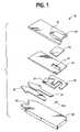
- FIG. 1represents an exploded view of the sensor of the present invention.
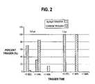
- FIG. 2is a graphical representation of the functionality of a sensor made according to the present invention and one made according to standard techniques.
- FIG. 1The construction of the electrochemical sensor with which the present invention is concerned is illustrated by FIG. 1 .
- the sensor of the present inventionis made by several printing passes using inks of various compositions.
- the sensor 34is made up of insulating base 36 upon which is printed in sequence (typically by screen printing techniques) and counter electrode subunit 40 a , an electrical conductive pattern consisting of the conductive leads ( 38 ) and the counter electrode sub-element 40 A.
- this sub-element 40 ais a discrete unit, but it could form a continuous trace to the conductive leads ( 38 ).
- the electrode pattern to which 39 is the working electrode and 40 is the counter electrodeis produced next.
- the electrodesare covered with an insulating (dielectric) pattern 42 with a slot 41 to expose the sub-element to the reaction layer 44 .
- the function of the reaction layeris to convert glucose, or other analyte in the fluid test sample, stoichiometrically into a chemical species which is electrochemically measurable in terms of an electrode pattern produced by the components of the electrode pattern.
- the reaction layertypically contains an enzyme which reacts with the analyte to produce mobile electrons, and an electron acceptor (mediator) such as ferricyanide to carry the mobile electrons to the surface of the working electrode.
- the enzyme in the reaction layercan be combined with a hydrophillic polymer such as carboxymethylcellulose or poly(ethylene oxide).
- the two parts, 39 and 40 , of the electrode printprovide the working 39 and counter 40 electrodes necessary for the electrochemical determination of the analyte which is the crux of the present invention.
- the working and counter electrodesare configured in a manner such that the major portion of the counter electrode is located downstream (in terms of the direction of the fluid flow along the flow path) from the forward portion of the working electrode 39 .
- sub-element 40 a of the counter electrodeis positioned upstream from the forward element of the working electrode 39 , so that when an inadequate amount of fluid test sample to completely cover the working electrode enters the capillary space, there will be formed an electrical connection between counter electrode sub-element 40 a and the exposed portion of the upper part of the working electrode due to the conductivity of the fluid sample, e.g. blood.
- the sensor systemcan be designed to actively advise the user that insufficient blood has entered the sensor's cavity and that another test for analyte concentration should be conducted.
- the systemis designed to give an error signal in the case of a short fill by generating a current profile when the capillary space is underfilled which is different from that which is obtained when there is complete filling of the capillary space.
- this designrequires more time than is desirable to activate the assay, which delay may be caused by a lower initial current being generated by the electrodes.
- this delaycan be shortened or eliminated by printing the sub-element of the counter electrode with an ink which comprises an electroactive material with the electroactive material being present in an amount which is insufficient to maintain the flow of electrons through the detector to constitute a valid determination of analyte concentration.
- the sub-elementis designed to allow a sufficient flow of electrons through the detector to start the timing sequence of the instrument.
- electroactive materialis intended to mean material which is sufficiently positive to allow oxidation to occur at the working electrode under the applied potential.
- Suitable electroactive materialsinclude AgO or other electropositive metal oxide such as, for example, the oxide of Cu, Mn, Pb, Hg, Ni, Co, Bi, Re or Te or compounds made from these metals.
- Other classes of electropositive materials which can be usedare oxides of metals including those mentioned above and halides of such metals.
- a metal capable of forming an electropositive metal oxidesuch as by auto oxidation can be applied to the sub-element of the counter electrode and then oxidized in place to form the metal oxide.
- electropositive materialis as stated above. Accordingly, compounds of an electropositive metal such as AgCl can be used since the Ag can be converted to the AgCl species upon contact of the sub-element with a fluid test sample such as plasma or whole blood which contains chloride.
- a fluid test samplesuch as plasma or whole blood which contains chloride.
- the sensor of the present inventionis constructed using several screen printing passes using inks of various compositions.
- the ink for the first passcomprises a material which is of sufficiently low resistance to serve as the conductive leads ( 38 ) and contains the electropositive material that forms the sub-element of the counter electrode ( 40 a ) as shown in FIG. I.
- the second passprovides the electrodes 39 and 40 which typically comprise a material incorporating carbon, graphite, palladium or platinum.
- the electropositive materialwhich can be an oxidizable metal such as one of the metals set out above. As an example, when silver is used, the silver at the surface of the sub-element is oxidized through the curing of the ink or by a secondary oxidizing step.
- This silver oxidewhen contacted with the blood sample which also reaches the working electrode, provides the necessary positive potential to produce the tripping current to start the meter's timing sequence.
- the sub-element(trigger) cannot support the full current generated from the reaction layer which results in the detector determining that the capillary space has not received sufficient test fluid to constitute a valid test.
- the area of the sub-element of the counter electrodeis typically less than that of the working electrode. This element is made as small as possible in view of the restraints of the screen printing process. The area which is exposed to the fluid test sample can be made even smaller by printing the dielectric layer 42 , so that only a very small portion (2% to 7% of the area of the working electrode) is exposed to provide the sub-element of the counter electrode.
- reaction layer 44can be denied contact with the sub-element 40 a of the counter electrode by providing a screen that does not allow printing of reagent ink over the counter electrode sub-element 40 a and serves the purpose of starving the sub-element for reagent thereby not allowing it to function as a proper counter electrode. This is preferred, so that an error condition is achieved in the case of failure of the test fluid to contact the bulk of the counter electrode 40 .
- sub-element 40 ais depicted as being physically disconnected from the rest of the conductive leads ( 38 ) in the drawing, it can be physically connected to them forming one continuous path on the counter electrode side. In the embodiment where the sub-element is physically disconnected from the main body of the counter electrode, it is provided with its own connection to the detector through the main body of the counter electrode.
- the two parts 39 and 40 of the printed electrodesprovide the working and counter electrodes necessary for the electrochemical determination of the analyte.
- the electrode inkwhich is about 14 ⁇ m thick, typically contains electrochemically active carbon.
- Components of the conductor inkare preferably a mixture of carbon and silver which is chosen to provide a path of low electrical resistance between the electrodes and the detector with which they are in operative connection via contact with the conductive pattern at the fish-tail end 45 of the type of sensor depicted in the drawing.
- the counter electrodecan be comprised of silver/silver chloride in which case it will function more like a reference electrode.
- the function of the dielectric pattern 42is to insulate the electrodes from the fluid test sample except in a defined area near the center of the electrode patterns to enhance the reproducibility of the detector reading.
- a defined areais important in this type of electrochemical determination because the measured current is dependent both on the concentration of the analyte and the area of the reaction layer which is exposed to the analyte containing test sample.
- a typical dielectric layer 42comprises a UV cured acrylic modified polymethane which is about 10 ⁇ thick.
- the capillary spaceis formed by mating the embossed lid 46 with base 36 after the various layers have been printed.
- Outlet 50serves as a vent for air so that the test fluid can be drawn into the capillary.
- the sensoris constructed using various layers of polymer thick film (PTF) to form the working sensor.
- the conductive leads and trigger subunitis printed from any standard conductive PTF utilizing a metal pigment for high conductivity.
- a thermoplastic silver/graphite PTFwas used for its cost advantage and cured in an air furnace.
- the working and counter electrodeswere printed using a standard carbon/graphite PTF and the area can be defined using a standard UV or conventional dielectric PTF.
- the curing of the PTFconverts the silver to silver oxide on the PTF surface. Any remaining silver on the surface of the trigger sub-electrode is further converted using an oxygen plasma process that is currently used to improve the performance of the working electrode surface as disclosed in U.S. Pat. No. 5,429,735.
- This plasma processcould also use a halide gas that can react with the metal to form a metal halide at the surface.
- any wet chemical reaction capable of oxidizing the silvercould be used as long as it does not adversely affect the performance of the carbon/graphite electrode.
- the sensoris then printed with a proprietary reagent PTF to form the working base.
- the lidis then attached to form the working cell of the sensor.
- the sensorcan be constructed using various layers of PTF's where the trigger PTF has incorporated in it a metal oxide or metal halide.
- the advantage of this systemis that it does not need to be converted to form the necessary electropositive material.
- a specialty PTF inkis made using AgO and graphite to form the conductive leads. This ink is screen printed as previously described except that the AgO is not formed during the subsequent air curing or O 2 plasma treatment.
- the electrode and dielectric PTFis printed and cured as in Example I.
- metal oxidescan be used in the manufacture of the PTF, but depending on the conductivity of the oxide it may not function as well for the conducting leads, so that a separate print from the conductive leads would be required. This would increase the cost of manufacturing the sensor due to the need for an additional printing layer.
- a base stocktypically of polycarbonate, is printed with various inks to form the electrodes 39 and 40 and then overcoated with a dielectric layer 42 in a predetermined pattern designed to leave a desired surface of the electrode exposed to contact by the fluid test sample as it enters the space formed by mating the lid 46 and the base 36 .
- the particular configuration of the dielectric layer 42is as depicted in FIG. 1 in which opening 43 leaves the reagent layer in electrical communication with the electrodes 39 and 40 is designed to define the extent to which all of the conductive elements (working, reference and sub-element electrodes) are exposed to the test fluid.
- the dielectric layerdefines the size of each of these elements.
- the electrodesare preferably printed so that the conductive and dielectric layers are close to 90 degrees to each other. This helps in the tolerance stackup for building the sensor because it reduces the registration issues since as either printing shifts around the element, definition remains constant.
- Two sensors having trigger electrodes as in FIG. 1one with a trigger electrode made of carbon and the other comprising Ag/AgO, were prepared as follows:
- a polycarbonate basewas printed using DuPont 5085 Ag/graphite conductive PTF ink and cured using either a standard forced air tunnel or an IR tunnel oven to form the conductive leads 38 .
- the electrodes 39 , 40 and 40 awere then printed using DuPont 7102T PTF ink. This ink can be cured using either the forced air tunnel or an IR tunnel oven.
- a dielectric inkwas applied to define the working, reference and trigger electrode area. The sensor was then subjected to an O 2 plasma treatment to enhance the electrode surfaces.
- the senorwas produced in the same manner as that with the carbon trigger except that the trigger electrode 40 a was printed with the Ag/graphite PTF ink along with the conductive leads 38 .
- the air curing of the DuPont PTF inks(5085 and 7102T) converted the Ag at the surface of the trigger electrode to AgO.
- the O 2 plasma used to enhance the electrode efficiencyfurther oxidized any residual Ag at the surface of the trigger electrode.
- the meterrequired that a minimum threshold current be obtained in order to start the timing sequence of the test.
- the mediatoris on the surface of the counter electrode and conversion of the glucose begins immediately to produce a current exceeding the threshold current.
- the mediatorIn an underfill condition, the mediator is situated several thousandths of an inch away from the trigger electrode. As the conversion of glucose occurs, the mediator must diffuse to the trigger electrode to produce the threshold current needed to start the meter timing sequence.
- the AgO or other electropositive specieshas a higher potential than the carbon and, therefore, the time required to render the threshold current is reduced.
- the trigger electrodeis not large enough to carry the full burden of the reaction and is, therefore, not suitable as the counter electrode.
- the meteris preprogrammed with algorithms which monitor the current profile to detect an underfill condition and give the user an error signal.
- the resulttermed countdown efficiency, was calculated inoculating the sensor with a known volume of blood (1.0 and 1.5 ⁇ L in this case) to produce an underfill condition. These volumes, through experimentation, have been determined to partially or fully cover the working electrode. The time required from sample inoculation until the meter starts its countdown was measured as countdown efficiency.
- the carbon triggeris effective at determining an underfill condition, but the user would have to wait anywhere from 1 second to 3 minutes before the meter would report an error.
- the present inventionwas found to decrease the time required for error detection to between 1 second and less than 1 minute depending on the degree of underfill.
Landscapes
- Chemical & Material Sciences (AREA)
- Health & Medical Sciences (AREA)
- Life Sciences & Earth Sciences (AREA)
- Organic Chemistry (AREA)
- Zoology (AREA)
- Engineering & Computer Science (AREA)
- Proteomics, Peptides & Aminoacids (AREA)
- Wood Science & Technology (AREA)
- Physics & Mathematics (AREA)
- General Health & Medical Sciences (AREA)
- Immunology (AREA)
- Biochemistry (AREA)
- Molecular Biology (AREA)
- Analytical Chemistry (AREA)
- General Engineering & Computer Science (AREA)
- Microbiology (AREA)
- Bioinformatics & Cheminformatics (AREA)
- Biotechnology (AREA)
- Biophysics (AREA)
- Genetics & Genomics (AREA)
- Hematology (AREA)
- Chemical Kinetics & Catalysis (AREA)
- Electrochemistry (AREA)
- General Physics & Mathematics (AREA)
- Pathology (AREA)
- Investigating Or Analysing Biological Materials (AREA)
- Measurement Of The Respiration, Hearing Ability, Form, And Blood Characteristics Of Living Organisms (AREA)
- Apparatus Associated With Microorganisms And Enzymes (AREA)
- Measuring Or Testing Involving Enzymes Or Micro-Organisms (AREA)
Abstract
Description
This is a continuation application of U.S. Ser. No. 10/382,170, filed Mar. 4, 2003, now abandoned, which claims the benefit of U.S. Provisional Application No. 60/363,380, filed on Mar. 7, 2002, which is incorporated by reference in its entirety.
The present invention relates to an electrochemical biosensor which can be used for the determination of analytes such as glucose in blood. Electrochemical biosensors of the type under consideration are disclosed in U.S. Pat. Nos. 5,120,420 and 5,798,031. These devices have an insulating base upon which carbon electrodes are printed and are then covered with a reagent layer comprising a hydrophilic material in combination with an oxidoreductase specific for the analyte. These devices typically involve a base and a cover which are separated by a generally U-shaped piece as a spacer element or, in the case of the '031 patent, use an embossed cover, so that when the base and cover are mated there is created a capillary space containing the electrodes and the reagent layer. A hydrophilic polymer, e.g. carboxymethyl cellulose or poly(ethylene oxide) is used to facilitate the drawing of the aqueous test fluid into the capillary space.
In either embodiment, working and counter electrodes are screen printed onto the base so that an electrochemically created current can flow when these electrodes are electrically connected and a potential is created between them. Touching the opening in the end of the sensor to a drop of test fluid such as blood results in the fluid being drawn into the capillary space, so that it covers the reaction layer on the surface of the electrode. An enzymatic reaction between the oxidoreductase and the analyte creates a flow of electrons which are carried to the working electrode by a mediator such as ferricyanide and flow through the working electrode to a meter which measures the magnitude of the flow. The counter electrode serves dual purposes. First, it provides a fixed potential against which the working electrode is controlled. Second, for a two electrode system, such as that depicted in the drawings, the counter electrode is used to complete the electrical circuit. In this mode, each electron that is transferred to the working electrode is returned to the test fluid at the counter electrode side of the cell. The device's software is programmed to correlate the magnitude of this flow with the concentration of analyte in the test sample. In order for this current to flow, a complete circuit is formed by covering both electrodes with the conductive fluid test sample and applying a potential therebetween.
A problem which is sometimes associated with this type of sensor occurs when an insufficient amount of blood is applied to the opening, so that the working and counter electrodes are not completely covered with the sample. This results in an incomplete current flowing across the electrodes, and, since the amount of analyte detected is directly proportional to the current flowing through the detection meter, failure to completely cover the sensor's electrodes can result in an artificially low reading of the sample's analyte concentration. One technique for dealing with this under filling problem is discussed in U.S. Pat. No. 5,628,890 which involves a mechanism for preventing any response from being detected when the sample volume is too low to provide an accurate reading.
In co-pending application Ser. No. 09/731,943 there is disclosed an electrochemical sensor of the type described above in which a small sub-element of the non-working electrode is positioned upstream from the working electrode, so that when there is insufficient flow of electrical current through the detector to constitute a valid test for the concentration of analyte in the fluid test sample, the pre-programmed detector causes the emission of an error signal to alert the user of the device that the test result should be disregarded. This is achievable because there is generated an altered current profile in the event that the capillary space of the sensor is underfilled. However, in this device, the tripping current carried by the straight carbon sub-element requires some time to reach the necessary potential thereby increasing the duration of the test.
The present invention is an improvement to an electrochemical sensor for determining the concentration of an analyte in a fluid test sample, e.g. glucose in blood. The sensor comprises:
- 1) a non-conductive base which provides a flow path for the fluid test sample and has a counter electrode and a working electrode on its upper surface which are in electrical communication with a detector of electrical current;
- 2) a reaction layer on at least the upper surface of the working electrode comprising an enzyme and a mediator which reacts with the analyte to cause electrons to be transferred between the analyte and the working electrode; and
- 3) a cover which when mated with the base forms a capillary space with an opening for the introduction of fluid test sample in which the working and counter electrodes are situated within the capillary space so that the major portion of the counter electrode is located downstream of the opening from the working electrode, with a sub-element of the counter electrode being upstream from the working electrode, so that when electrical communication between only the sub-element of the counter electrode and the working electrode takes place, there is insufficient flow of electrical current through the detector to constitute a valid test.
The improvement to the sensor involves the use of a sub-element of the counter electrode which comprises an electroactive material. The electroactive material is sufficiently (electro) positive to allow oxidation to occur at the working electrode under the applied potential and is present in an amount which is insufficient to maintain the flow of electric current through the detector to constitute a valid determination of analyte concentration.
The construction of the electrochemical sensor with which the present invention is concerned is illustrated byFIG. 1 . Referring toFIG. 1 , the sensor of the present invention is made by several printing passes using inks of various compositions. Thesensor 34 is made up ofinsulating base 36 upon which is printed in sequence (typically by screen printing techniques) andcounter electrode subunit 40a, an electrical conductive pattern consisting of the conductive leads (38) and the counter electrode sub-element40A.
In the drawing, thissub-element 40ais a discrete unit, but it could form a continuous trace to the conductive leads (38). The electrode pattern to which39 is the working electrode and40 is the counter electrode is produced next. The electrodes are covered with an insulating (dielectric)pattern 42 with aslot 41 to expose the sub-element to thereaction layer 44. The function of the reaction layer is to convert glucose, or other analyte in the fluid test sample, stoichiometrically into a chemical species which is electrochemically measurable in terms of an electrode pattern produced by the components of the electrode pattern. The reaction layer typically contains an enzyme which reacts with the analyte to produce mobile electrons, and an electron acceptor (mediator) such as ferricyanide to carry the mobile electrons to the surface of the working electrode. The enzyme in the reaction layer can be combined with a hydrophillic polymer such as carboxymethylcellulose or poly(ethylene oxide). The two parts,39 and40, of the electrode print provide the working39 and counter40 electrodes necessary for the electrochemical determination of the analyte which is the crux of the present invention. The working and counter electrodes are configured in a manner such that the major portion of the counter electrode is located downstream (in terms of the direction of the fluid flow along the flow path) from the forward portion of the workingelectrode 39. This configuration offers the advantage of allowing the test fluid to completely cover the exposed portion of the working electrode for all cases in which an undetected partial fill has occurred. However,sub-element 40aof the counter electrode is positioned upstream from the forward element of the workingelectrode 39, so that when an inadequate amount of fluid test sample to completely cover the working electrode enters the capillary space, there will be formed an electrical connection betweencounter electrode sub-element 40aand the exposed portion of the upper part of the working electrode due to the conductivity of the fluid sample, e.g. blood. By programming the current detector to give an error signal when the current profile it receives is below certain pre-determined levels, the sensor system can be designed to actively advise the user that insufficient blood has entered the sensor's cavity and that another test for analyte concentration should be conducted. The system is designed to give an error signal in the case of a short fill by generating a current profile when the capillary space is underfilled which is different from that which is obtained when there is complete filling of the capillary space. However, it was found that this design requires more time than is desirable to activate the assay, which delay may be caused by a lower initial current being generated by the electrodes. It has now been discovered that this delay can be shortened or eliminated by printing the sub-element of the counter electrode with an ink which comprises an electroactive material with the electroactive material being present in an amount which is insufficient to maintain the flow of electrons through the detector to constitute a valid determination of analyte concentration. Conversely, the sub-element is designed to allow a sufficient flow of electrons through the detector to start the timing sequence of the instrument.
The term electroactive material is intended to mean material which is sufficiently positive to allow oxidation to occur at the working electrode under the applied potential. Suitable electroactive materials include AgO or other electropositive metal oxide such as, for example, the oxide of Cu, Mn, Pb, Hg, Ni, Co, Bi, Re or Te or compounds made from these metals. Other classes of electropositive materials which can be used are oxides of metals including those mentioned above and halides of such metals. A metal capable of forming an electropositive metal oxide such as by auto oxidation can be applied to the sub-element of the counter electrode and then oxidized in place to form the metal oxide.
The only requirement of the electropositive material is as stated above. Accordingly, compounds of an electropositive metal such as AgCl can be used since the Ag can be converted to the AgCl species upon contact of the sub-element with a fluid test sample such as plasma or whole blood which contains chloride. This embodiment offers the advantage of not requiring a secondary operation to form the silver oxide layer on the electrode's surface.
The sensor of the present invention is constructed using several screen printing passes using inks of various compositions. The ink for the first pass comprises a material which is of sufficiently low resistance to serve as the conductive leads (38) and contains the electropositive material that forms the sub-element of the counter electrode (40a) as shown in FIG. I. The second pass provides theelectrodes
While the particular dimensions of the electrodes are not critical, the area of the sub-element of the counter electrode is typically less than that of the working electrode. This element is made as small as possible in view of the restraints of the screen printing process. The area which is exposed to the fluid test sample can be made even smaller by printing thedielectric layer 42, so that only a very small portion (2% to 7% of the area of the working electrode) is exposed to provide the sub-element of the counter electrode. In one embodiment,reaction layer 44 can be denied contact with the sub-element40aof the counter electrode by providing a screen that does not allow printing of reagent ink over thecounter electrode sub-element 40aand serves the purpose of starving the sub-element for reagent thereby not allowing it to function as a proper counter electrode. This is preferred, so that an error condition is achieved in the case of failure of the test fluid to contact the bulk of thecounter electrode 40.
While sub-element40ais depicted as being physically disconnected from the rest of the conductive leads (38) in the drawing, it can be physically connected to them forming one continuous path on the counter electrode side. In the embodiment where the sub-element is physically disconnected from the main body of the counter electrode, it is provided with its own connection to the detector through the main body of the counter electrode.
The twoparts tail end 45 of the type of sensor depicted in the drawing. The counter electrode can be comprised of silver/silver chloride in which case it will function more like a reference electrode. The function of thedielectric pattern 42 is to insulate the electrodes from the fluid test sample except in a defined area near the center of the electrode patterns to enhance the reproducibility of the detector reading. A defined area is important in this type of electrochemical determination because the measured current is dependent both on the concentration of the analyte and the area of the reaction layer which is exposed to the analyte containing test sample. Atypical dielectric layer 42 comprises a UV cured acrylic modified polymethane which is about 10μ thick.
InFIG. 1 , the capillary space is formed by mating the embossedlid 46 withbase 36 after the various layers have been printed.Outlet 50 serves as a vent for air so that the test fluid can be drawn into the capillary.
The present invention is further illustrated by the following examples:
The sensor is constructed using various layers of polymer thick film (PTF) to form the working sensor. The conductive leads and trigger subunit is printed from any standard conductive PTF utilizing a metal pigment for high conductivity. In this case, a thermoplastic silver/graphite PTF was used for its cost advantage and cured in an air furnace. The working and counter electrodes were printed using a standard carbon/graphite PTF and the area can be defined using a standard UV or conventional dielectric PTF. The curing of the PTF converts the silver to silver oxide on the PTF surface. Any remaining silver on the surface of the trigger sub-electrode is further converted using an oxygen plasma process that is currently used to improve the performance of the working electrode surface as disclosed in U.S. Pat. No. 5,429,735. This plasma process could also use a halide gas that can react with the metal to form a metal halide at the surface. Alternatively, any wet chemical reaction capable of oxidizing the silver could be used as long as it does not adversely affect the performance of the carbon/graphite electrode. The sensor is then printed with a proprietary reagent PTF to form the working base. The lid is then attached to form the working cell of the sensor.
The sensor can be constructed using various layers of PTF's where the trigger PTF has incorporated in it a metal oxide or metal halide. The advantage of this system is that it does not need to be converted to form the necessary electropositive material. In this example, a specialty PTF ink is made using AgO and graphite to form the conductive leads. This ink is screen printed as previously described except that the AgO is not formed during the subsequent air curing or O2plasma treatment. The electrode and dielectric PTF is printed and cured as in Example I.
Other metal oxides can be used in the manufacture of the PTF, but depending on the conductivity of the oxide it may not function as well for the conducting leads, so that a separate print from the conductive leads would be required. This would increase the cost of manufacturing the sensor due to the need for an additional printing layer.
A base stock, typically of polycarbonate, is printed with various inks to form theelectrodes dielectric layer 42 in a predetermined pattern designed to leave a desired surface of the electrode exposed to contact by the fluid test sample as it enters the space formed by mating thelid 46 and thebase 36. The particular configuration of thedielectric layer 42 is as depicted inFIG. 1 in which opening43 leaves the reagent layer in electrical communication with theelectrodes
Two sensors having trigger electrodes as inFIG. 1 , one with a trigger electrode made of carbon and the other comprising Ag/AgO, were prepared as follows:
Carbon Trigger Electrode
A polycarbonate base was printed using DuPont 5085 Ag/graphite conductive PTF ink and cured using either a standard forced air tunnel or an IR tunnel oven to form the conductive leads38. Theelectrodes
Ag/AgO Trigger
In this embodiment, the sensor was produced in the same manner as that with the carbon trigger except that thetrigger electrode 40awas printed with the Ag/graphite PTF ink along with the conductive leads38.
The air curing of the DuPont PTF inks (5085 and 7102T) converted the Ag at the surface of the trigger electrode to AgO. The O2plasma used to enhance the electrode efficiency further oxidized any residual Ag at the surface of the trigger electrode.
These sensors were tested by determining the time required for the counter electrode subunit to reach the tripping current. The meter required that a minimum threshold current be obtained in order to start the timing sequence of the test. In a complete fill situation, the mediator is on the surface of the counter electrode and conversion of the glucose begins immediately to produce a current exceeding the threshold current. In an underfill condition, the mediator is situated several thousandths of an inch away from the trigger electrode. As the conversion of glucose occurs, the mediator must diffuse to the trigger electrode to produce the threshold current needed to start the meter timing sequence. The AgO or other electropositive species has a higher potential than the carbon and, therefore, the time required to render the threshold current is reduced. The trigger electrode is not large enough to carry the full burden of the reaction and is, therefore, not suitable as the counter electrode. The meter is preprogrammed with algorithms which monitor the current profile to detect an underfill condition and give the user an error signal. The result, termed countdown efficiency, was calculated inoculating the sensor with a known volume of blood (1.0 and 1.5 μL in this case) to produce an underfill condition. These volumes, through experimentation, have been determined to partially or fully cover the working electrode. The time required from sample inoculation until the meter starts its countdown was measured as countdown efficiency.
From the data presented inFIG. 2 , it can be determined that the carbon trigger is effective at determining an underfill condition, but the user would have to wait anywhere from 1 second to 3 minutes before the meter would report an error. The present invention was found to decrease the time required for error detection to between 1 second and less than 1 minute depending on the degree of underfill.
For Ag/AgO at 1.0 μL, 70% of the tested sensors tripped immediately and another 30% tripped in less than 1 minute. At 1.5 μL, 100% of the sensors tripped immediately.
For carbon at 1.0 μL, 84% tripped in less than 1 minute and 16% never tripped until the meter errored out at 3 minutes. At 1.5 μL, 100% tripped within 1 minute.
Claims (30)
1. An electrochemical test sensor for detecting the concentration of an analyte in a fluid test sample, the test sensor comprising:
a non-conductive base that provides a flow path for the fluid test sample, the base including a counter electrode, a working electrode and a sub-element on an upper surface thereof, the counter and working electrodes being adapted to be in electrical communication with a detector of electrical current, the sub-element being physically disconnected from the counter electrode, the sub-element comprising an electroactive material that is adapted to allow oxidation to occur at the surface of the working electrode under an applied potential;
a reaction layer on at least the surface of the working electrode, the reaction layer comprising an enzyme; and
a cover coupled with the non-conductive base and forming a capillary space with an opening for the introduction of the fluid test sample thereto, the space forming a flow path for the fluid test sample,
wherein the sub-element of the counter electrode is located upstream from the working electrode relative to the opening such that when electrochemical communication occurs between only the sub-element and the working electrode there is insufficient flow of electrical current through a detector to constitute a valid determination of the analyte concentration in the fluid test sample.
2. The test sensor ofclaim 1 further comprising an insulating layer, the insulating layer exposing a portion of the sub-element to the reaction layer.
3. The test sensor ofclaim 1 wherein the reaction layer further comprises a mediator.
4. The test sensor ofclaim 3 wherein the mediator is ferricyanide.
5. The test sensor ofclaim 1 wherein the reaction layer further comprises poly(ethylene) oxide.
6. The test sensor ofclaim 1 wherein the enzyme is glucose oxidase.
7. The test sensor ofclaim 1 wherein the electroactive material is an oxide of Ag, Cu, Mn, Pb, Hg, Ni, Co, Bi, Re, or Te.
8. The test sensor ofclaim 7 wherein the electroactive material is AgO.
9. The test sensor ofclaim 1 wherein the electroactive material is a metal halide.
10. The test sensor ofclaim 1 wherein the cover has a concave portion, the concave portion forming the capillary space when the cover is coupled with the non-conductive base.
11. The test sensor ofclaim 1 further including a spacer element with a U-shaped indentation, the U-shaped indentation being located between the cover and the non-conductive base and forming the capillary space.
12. The test sensor ofclaim 1 wherein a major portion of the counter electrode is located downstream relative to the opening and at least a portion of the working electrode.
13. The test sensor ofclaim 1 wherein the area of the sub-element is less than the area of the working electrode.
14. An electrochemical test sensor adapted to assist in determining the concentration of an analyte in a fluid test sample, the test sensor comprising:
a base assisting in forming an opening for introducing the fluid test sample;
a working electrode being coupled to the base;
a counter electrode being coupled to the base, the counter electrode and the working electrode being adapted to be in electrical communication with a detector of electrical current, a portion of the counter electrode being located downstream relative to the opening and at least a portion of the working electrode; and
a sub-element being coupled to the base, the sub-element being physically disconnected from the counter electrode, the sub-element comprising an electroactive material that is adapted to allow oxidation to occur at the surface of the working electrode under an applied potential, the sub-element of the counter electrode being located upstream from the working electrode relative to the opening such that when electrochemical communication occurs between only the sub-element and the working electrode there is insufficient flow of electrical current through a detector to constitute a valid determination of the analyte concentration in the fluid test sample.
15. The test sensor ofclaim 14 further comprising a cover adapted to be coupled to the base to form a capillary space, the capillary space having an opening for introducing the fluid test sample therein, the capillary space forming a flow path for the fluid test sample, the working electrode and the counter electrode being situated in the flow path.
16. The test sensor ofclaim 15 wherein the cover has a concave portion, the concave portion forming the capillary space when the cover is coupled with the base.
17. The test sensor ofclaim 15 further including a spacer element with a U-shaped indentation, the U-shaped indentation being located between the cover and the base and forming the capillary space.
18. The test sensor ofclaim 14 further comprising a reaction layer located on the surface of at least the working electrode, the reaction layer comprising an enzyme adapted to react with the analyte.
19. The test sensor ofclaim 14 wherein the reaction layer further comprises poly(ethylene) oxide.
20. The test sensor ofclaim 14 wherein the enzyme is glucose oxidase.
21. The test sensor ofclaim 14 wherein the electroactive material is an oxide of Ag, Cu, Mn, Pb, Hg, Ni, Co, Bi, Re, or Te.
22. The test sensor ofclaim 14 wherein the electroactive material is a metal halide.
23. A method of determining whether a sufficient quantity of a fluid test sample has been introduced to an electrochemical test sensor, the method comprising the acts of:
providing the electrochemical test sensor adapted to assist in determining the concentration of an analyte in a fluid test sample, the sensor comprising a base, a working electrode, a counter electrode and a sub-element, the base assisting in forming an opening for introducing the fluid test sample, the working electrode being coupled to the base, the counter electrode being coupled to the base, the counter electrode and the working electrode being adapted to be in electrical communication with a detector of electrical current, at least a portion of the counter electrode being located downstream relative to the opening and at least a portion of the working electrode, the sub-element being coupled to the base, the sub-element being physically disconnected from the counter electrode, the sub-element comprising an electroactive material that is adapted to allow oxidation to occur at the surface of the working electrode under an applied potential, the sub-element of the counter electrode being located upstream from the working electrode relative to the opening such that when electrochemical communication occurs between only the sub-element and the working electrode there is insufficient flow of electrical current through a detector to constitute a valid determination of the analyte concentration in the fluid test sample;
introducing the fluid test sample to the test sensor; and
determining whether a sufficient quantity of the fluid test sample has been introduced and, if not, notifying a user that an insufficient quantity of the fluid test sample has been introduced.
24. The method ofclaim 23 , wherein the test sensor further comprises a cover adapted to be coupled to the base to form a capillary space, the capillary space having an opening for introducing the fluid test sample therein, the capillary space forming a flow path for the fluid test sample, the working electrode and the counter electrode being situated in the flow path.
25. The method ofclaim 24 wherein the cover has a concave portion, the concave portion forming the capillary space when the cover is coupled with the base.
26. The method ofclaim 24 further including a spacer element with a U-shaped indentation, the U-shaped indentation located between the cover and the base and forming the capillary space.
27. The method ofclaim 23 wherein the test sensor further comprises a reaction layer located on the surface of at least the working electrode, the reaction layer comprising an enzyme adapted to react with the analyte.
28. The method ofclaim 23 wherein the electroactive material is an oxide of Ag, Cu, Mn, Pb, Hg, Ni, Co, Bi, Re, or Te.
29. The method ofclaim 23 wherein the electroactive material is a metal halide.
30. The method ofclaim 23 wherein the analyte is glucose.
Priority Applications (1)
| Application Number | Priority Date | Filing Date | Title |
|---|---|---|---|
| US10/978,889US7118668B1 (en) | 2002-03-07 | 2004-11-01 | Electrochemical test sensor |
Applications Claiming Priority (3)
| Application Number | Priority Date | Filing Date | Title |
|---|---|---|---|
| US36338002P | 2002-03-07 | 2002-03-07 | |
| US10/382,170US20040007461A1 (en) | 2002-03-07 | 2003-03-04 | Electrical sensor |
| US10/978,889US7118668B1 (en) | 2002-03-07 | 2004-11-01 | Electrochemical test sensor |
Related Parent Applications (1)
| Application Number | Title | Priority Date | Filing Date |
|---|---|---|---|
| US10/382,170ContinuationUS20040007461A1 (en) | 2002-03-07 | 2003-03-04 | Electrical sensor |
Publications (2)
| Publication Number | Publication Date |
|---|---|
| US20060219551A1 US20060219551A1 (en) | 2006-10-05 |
| US7118668B1true US7118668B1 (en) | 2006-10-10 |
Family
ID=27757795
Family Applications (2)
| Application Number | Title | Priority Date | Filing Date |
|---|---|---|---|
| US10/382,170AbandonedUS20040007461A1 (en) | 2002-03-07 | 2003-03-04 | Electrical sensor |
| US10/978,889Expired - Fee RelatedUS7118668B1 (en) | 2002-03-07 | 2004-11-01 | Electrochemical test sensor |
Family Applications Before (1)
| Application Number | Title | Priority Date | Filing Date |
|---|---|---|---|
| US10/382,170AbandonedUS20040007461A1 (en) | 2002-03-07 | 2003-03-04 | Electrical sensor |
Country Status (7)
| Country | Link |
|---|---|
| US (2) | US20040007461A1 (en) |
| EP (1) | EP1343007B1 (en) |
| JP (1) | JP3999148B2 (en) |
| AU (1) | AU2003200788B2 (en) |
| CA (1) | CA2419213C (en) |
| DK (1) | DK1343007T3 (en) |
| ES (1) | ES2399092T3 (en) |
Cited By (79)
| Publication number | Priority date | Publication date | Assignee | Title |
|---|---|---|---|---|
| US7297151B2 (en) | 2002-04-19 | 2007-11-20 | Elikan Technologies, Inc. | Method and apparatus for body fluid sampling with improved sensing |
| US7316700B2 (en) | 2001-06-12 | 2008-01-08 | Pelikan Technologies, Inc. | Self optimizing lancing device with adaptation means to temporal variations in cutaneous properties |
| US20080011616A1 (en)* | 2006-07-11 | 2008-01-17 | Bayer Healthcare Llc | Electrochemical test sensor |
| US7344894B2 (en) | 2001-10-16 | 2008-03-18 | Agilent Technologies, Inc. | Thermal regulation of fluidic samples within a diagnostic cartridge |
| US7344507B2 (en) | 2002-04-19 | 2008-03-18 | Pelikan Technologies, Inc. | Method and apparatus for lancet actuation |
| US7374544B2 (en) | 2002-04-19 | 2008-05-20 | Pelikan Technologies, Inc. | Method and apparatus for penetrating tissue |
| US7410468B2 (en) | 2002-04-19 | 2008-08-12 | Pelikan Technologies, Inc. | Method and apparatus for penetrating tissue |
| US7481776B2 (en) | 2002-04-19 | 2009-01-27 | Pelikan Technologies, Inc. | Method and apparatus for penetrating tissue |
| US7491178B2 (en) | 2002-04-19 | 2009-02-17 | Pelikan Technologies, Inc. | Method and apparatus for penetrating tissue |
| US20090095071A1 (en)* | 2006-05-03 | 2009-04-16 | Bayer Healthcare Llc | Underfill Detection System For A Biosensor |
| US7524293B2 (en) | 2002-04-19 | 2009-04-28 | Pelikan Technologies, Inc. | Method and apparatus for penetrating tissue |
| US7537571B2 (en) | 2001-06-12 | 2009-05-26 | Pelikan Technologies, Inc. | Integrated blood sampling analysis system with multi-use sampling module |
| US20090145755A1 (en)* | 2007-12-10 | 2009-06-11 | Bayer Healthcare Llc | Wear-resistant electrochemical test sensor and method of forming the same |
| US7547287B2 (en) | 2002-04-19 | 2009-06-16 | Pelikan Technologies, Inc. | Method and apparatus for penetrating tissue |
| US7563232B2 (en) | 2002-04-19 | 2009-07-21 | Pelikan Technologies, Inc. | Method and apparatus for penetrating tissue |
| US7582099B2 (en) | 2002-04-19 | 2009-09-01 | Pelikan Technologies, Inc | Method and apparatus for penetrating tissue |
| US7582063B2 (en) | 2000-11-21 | 2009-09-01 | Pelikan Technologies, Inc. | Blood testing apparatus having a rotatable cartridge with multiple lancing elements and testing means |
| US7604592B2 (en) | 2003-06-13 | 2009-10-20 | Pelikan Technologies, Inc. | Method and apparatus for a point of care device |
| US7648468B2 (en) | 2002-04-19 | 2010-01-19 | Pelikon Technologies, Inc. | Method and apparatus for penetrating tissue |
| US20100012509A1 (en)* | 2007-01-05 | 2010-01-21 | Bayer Healthcare Llc | Electrochemical Test Sensor With Light Guide |
| US7666149B2 (en) | 1997-12-04 | 2010-02-23 | Peliken Technologies, Inc. | Cassette of lancet cartridges for sampling blood |
| US7674232B2 (en) | 2002-04-19 | 2010-03-09 | Pelikan Technologies, Inc. | Method and apparatus for penetrating tissue |
| US7682318B2 (en) | 2001-06-12 | 2010-03-23 | Pelikan Technologies, Inc. | Blood sampling apparatus and method |
| US7699791B2 (en) | 2001-06-12 | 2010-04-20 | Pelikan Technologies, Inc. | Method and apparatus for improving success rate of blood yield from a fingerstick |
| US7713214B2 (en) | 2002-04-19 | 2010-05-11 | Pelikan Technologies, Inc. | Method and apparatus for a multi-use body fluid sampling device with optical analyte sensing |
| US7717863B2 (en) | 2002-04-19 | 2010-05-18 | Pelikan Technologies, Inc. | Method and apparatus for penetrating tissue |
| US7731729B2 (en) | 2002-04-19 | 2010-06-08 | Pelikan Technologies, Inc. | Method and apparatus for penetrating tissue |
| US7822454B1 (en) | 2005-01-03 | 2010-10-26 | Pelikan Technologies, Inc. | Fluid sampling device with improved analyte detecting member configuration |
| US7833171B2 (en) | 2002-04-19 | 2010-11-16 | Pelikan Technologies, Inc. | Method and apparatus for penetrating tissue |
| US20100288841A1 (en)* | 2009-05-14 | 2010-11-18 | Bayer Healthcare Llc | Calibration coded sensors and apparatus, systems and methods for reading same |
| US7841992B2 (en) | 2001-06-12 | 2010-11-30 | Pelikan Technologies, Inc. | Tissue penetration device |
| US7850621B2 (en) | 2003-06-06 | 2010-12-14 | Pelikan Technologies, Inc. | Method and apparatus for body fluid sampling and analyte sensing |
| US7862520B2 (en) | 2002-04-19 | 2011-01-04 | Pelikan Technologies, Inc. | Body fluid sampling module with a continuous compression tissue interface surface |
| US7874994B2 (en) | 2002-04-19 | 2011-01-25 | Pelikan Technologies, Inc. | Method and apparatus for penetrating tissue |
| US7892183B2 (en) | 2002-04-19 | 2011-02-22 | Pelikan Technologies, Inc. | Method and apparatus for body fluid sampling and analyte sensing |
| US7901362B2 (en) | 2002-04-19 | 2011-03-08 | Pelikan Technologies, Inc. | Method and apparatus for penetrating tissue |
| US20110061458A1 (en)* | 2004-02-06 | 2011-03-17 | Bayer Healthcare, Llc. | Methods Of Using An Electrochemical Biosensor |
| US7909778B2 (en) | 2002-04-19 | 2011-03-22 | Pelikan Technologies, Inc. | Method and apparatus for penetrating tissue |
| US7909775B2 (en) | 2001-06-12 | 2011-03-22 | Pelikan Technologies, Inc. | Method and apparatus for lancet launching device integrated onto a blood-sampling cartridge |
| US7914465B2 (en) | 2002-04-19 | 2011-03-29 | Pelikan Technologies, Inc. | Method and apparatus for penetrating tissue |
| US7959582B2 (en) | 2002-04-19 | 2011-06-14 | Pelikan Technologies, Inc. | Method and apparatus for penetrating tissue |
| US7976476B2 (en) | 2002-04-19 | 2011-07-12 | Pelikan Technologies, Inc. | Device and method for variable speed lancet |
| US20110231105A1 (en)* | 2010-03-22 | 2011-09-22 | Bayer Healthcare Llc | Residual Compensation Including Underfill Error |
| WO2012064648A1 (en) | 2010-11-12 | 2012-05-18 | Bayer Healthcare Llc | Auto-coded analyte sensors and apparatus, systems, and methods for detecting same |
| US8197421B2 (en) | 2002-04-19 | 2012-06-12 | Pelikan Technologies, Inc. | Method and apparatus for penetrating tissue |
| US8221334B2 (en) | 2002-04-19 | 2012-07-17 | Sanofi-Aventis Deutschland Gmbh | Method and apparatus for penetrating tissue |
| US8267870B2 (en) | 2002-04-19 | 2012-09-18 | Sanofi-Aventis Deutschland Gmbh | Method and apparatus for body fluid sampling with hybrid actuation |
| US8282576B2 (en) | 2003-09-29 | 2012-10-09 | Sanofi-Aventis Deutschland Gmbh | Method and apparatus for an improved sample capture device |
| US8333710B2 (en) | 2002-04-19 | 2012-12-18 | Sanofi-Aventis Deutschland Gmbh | Tissue penetration device |
| US8435190B2 (en) | 2002-04-19 | 2013-05-07 | Sanofi-Aventis Deutschland Gmbh | Method and apparatus for penetrating tissue |
| US8439872B2 (en) | 1998-03-30 | 2013-05-14 | Sanofi-Aventis Deutschland Gmbh | Apparatus and method for penetration with shaft having a sensor for sensing penetration depth |
| USRE44521E1 (en) | 1999-08-02 | 2013-10-08 | Bayer Healthcare Llc | Electrochemical-sensor design |
| US8652831B2 (en) | 2004-12-30 | 2014-02-18 | Sanofi-Aventis Deutschland Gmbh | Method and apparatus for analyte measurement test time |
| US8668656B2 (en) | 2003-12-31 | 2014-03-11 | Sanofi-Aventis Deutschland Gmbh | Method and apparatus for improving fluidic flow and sample capture |
| US8702624B2 (en) | 2006-09-29 | 2014-04-22 | Sanofi-Aventis Deutschland Gmbh | Analyte measurement device with a single shot actuator |
| US8721671B2 (en) | 2001-06-12 | 2014-05-13 | Sanofi-Aventis Deutschland Gmbh | Electric lancet actuator |
| US8828203B2 (en) | 2004-05-20 | 2014-09-09 | Sanofi-Aventis Deutschland Gmbh | Printable hydrogels for biosensors |
| US8965476B2 (en) | 2010-04-16 | 2015-02-24 | Sanofi-Aventis Deutschland Gmbh | Tissue penetration device |
| US9034639B2 (en) | 2002-12-30 | 2015-05-19 | Sanofi-Aventis Deutschland Gmbh | Method and apparatus using optical techniques to measure analyte levels |
| US9072842B2 (en) | 2002-04-19 | 2015-07-07 | Sanofi-Aventis Deutschland Gmbh | Method and apparatus for penetrating tissue |
| US9144401B2 (en) | 2003-06-11 | 2015-09-29 | Sanofi-Aventis Deutschland Gmbh | Low pain penetrating member |
| US9188561B2 (en)* | 2013-03-03 | 2015-11-17 | Yue Xu | Test strip |
| US9222910B2 (en) | 2010-06-07 | 2015-12-29 | Bayer Healthcare Llc | Underfill management system for a biosensor |
| US9226699B2 (en) | 2002-04-19 | 2016-01-05 | Sanofi-Aventis Deutschland Gmbh | Body fluid sampling module with a continuous compression tissue interface surface |
| US9248267B2 (en) | 2002-04-19 | 2016-02-02 | Sanofi-Aventis Deustchland Gmbh | Tissue penetration device |
| US9314194B2 (en) | 2002-04-19 | 2016-04-19 | Sanofi-Aventis Deutschland Gmbh | Tissue penetration device |
| US9351680B2 (en) | 2003-10-14 | 2016-05-31 | Sanofi-Aventis Deutschland Gmbh | Method and apparatus for a variable user interface |
| US9375169B2 (en) | 2009-01-30 | 2016-06-28 | Sanofi-Aventis Deutschland Gmbh | Cam drive for managing disposable penetrating member actions with a single motor and motor and control system |
| US9386944B2 (en) | 2008-04-11 | 2016-07-12 | Sanofi-Aventis Deutschland Gmbh | Method and apparatus for analyte detecting device |
| US9427532B2 (en) | 2001-06-12 | 2016-08-30 | Sanofi-Aventis Deutschland Gmbh | Tissue penetration device |
| US9560993B2 (en) | 2001-11-21 | 2017-02-07 | Sanofi-Aventis Deutschland Gmbh | Blood testing apparatus having a rotatable cartridge with multiple lancing elements and testing means |
| US9775806B2 (en) | 2011-09-21 | 2017-10-03 | Ascensia Diabetes Care Holdings Ag | Analysis compensation including segmented signals |
| US9795747B2 (en) | 2010-06-02 | 2017-10-24 | Sanofi-Aventis Deutschland Gmbh | Methods and apparatus for lancet actuation |
| US9820684B2 (en) | 2004-06-03 | 2017-11-21 | Sanofi-Aventis Deutschland Gmbh | Method and apparatus for a fluid sampling device |
| US9839386B2 (en) | 2002-04-19 | 2017-12-12 | Sanofi-Aventis Deustschland Gmbh | Body fluid sampling device with capacitive sensor |
| US10154806B2 (en) | 2009-12-17 | 2018-12-18 | Ascensia Diabetes Care Holdings Ag | Apparatus, systems, and methods for determining and displaying pre-event and post-event analyte concentration levels |
| US10291973B2 (en)* | 2015-05-14 | 2019-05-14 | Knowles Electronics, Llc | Sensor device with ingress protection |
| CN110302792A (en)* | 2019-07-15 | 2019-10-08 | 广西师范大学 | A kind of carbon nanotube load NiCeOxComposite catalyst and the preparation method and application thereof |
| WO2022148876A1 (en) | 2021-01-11 | 2022-07-14 | Ascensia Diabetes Care Holdings Ag | Analyte meters, test strip ejectors, and methods of using same |
Families Citing this family (15)
| Publication number | Priority date | Publication date | Assignee | Title |
|---|---|---|---|---|
| US8007656B2 (en)* | 2003-10-24 | 2011-08-30 | Bayer Healthcare Llc | Enzymatic electrochemical biosensor |
| KR101191093B1 (en)* | 2004-02-06 | 2012-10-15 | 바이엘 헬쓰케어, 엘엘씨 | Fluid testing sensor having vents for directing fluid flow |
| EP1713926B1 (en)* | 2004-02-06 | 2012-08-01 | Bayer HealthCare, LLC | Oxidizable species as an internal reference for biosensors and method of use |
| US7807043B2 (en) | 2004-02-23 | 2010-10-05 | Oakville Hong Kong Company Limited | Microfluidic test device |
| WO2005103663A1 (en)* | 2004-04-23 | 2005-11-03 | Arkray, Inc. | Analyzer and method of manufacturing the same |
| ATE514942T1 (en) | 2006-04-10 | 2011-07-15 | Bayer Healthcare Llc | CORRECTION OF OXYGEN EFFECTS IN A TEST SENSOR USING REAGENTS |
| US7797987B2 (en)* | 2006-10-11 | 2010-09-21 | Bayer Healthcare Llc | Test sensor with a side vent and method of making the same |
| US20100066356A1 (en)* | 2006-12-15 | 2010-03-18 | Koninklijke Philips Electronics N.V. | Sensor device comprising means for determining the sample covered area of the sensitive surface |
| US8506908B2 (en)* | 2007-03-09 | 2013-08-13 | Vantix Holdings Limited | Electrochemical detection system |
| US20080221805A1 (en)* | 2007-03-09 | 2008-09-11 | David Richard Andrews | Multi-channel lock-in amplifier system and method |
| WO2009076302A1 (en) | 2007-12-10 | 2009-06-18 | Bayer Healthcare Llc | Control markers for auto-detection of control solution and methods of use |
| KR102119301B1 (en) | 2015-06-15 | 2020-06-05 | 에프. 호프만-라 로슈 아게 | Method and test element for electrochemically detecting at least one analyte in a sample of a body fluid |
| HUE071465T2 (en) | 2016-06-29 | 2025-08-28 | Hoffmann La Roche | Galvanically functionalized sensors |
| TWI768561B (en)* | 2020-11-25 | 2022-06-21 | 五鼎生物技術股份有限公司 | Biochemical test chip |
| TWI768560B (en) | 2020-11-25 | 2022-06-21 | 五鼎生物技術股份有限公司 | Biochemical test chip |
Citations (14)
| Publication number | Priority date | Publication date | Assignee | Title |
|---|---|---|---|---|
| JPH01262470A (en) | 1988-04-12 | 1989-10-19 | Fuji Photo Film Co Ltd | Dry process whole blood analysing element |
| US4935346A (en) | 1986-08-13 | 1990-06-19 | Lifescan, Inc. | Minimum procedure system for the determination of analytes |
| US5049394A (en) | 1987-09-11 | 1991-09-17 | E. R. Squibb & Sons, Inc. | Pharmaceutical composition containing high drug load and method for preparing same |
| US5049487A (en) | 1986-08-13 | 1991-09-17 | Lifescan, Inc. | Automated initiation of timing of reflectance readings |
| US5128015A (en)* | 1988-03-15 | 1992-07-07 | Tall Oak Ventures | Method and apparatus for amperometric diagnostic analysis |
| US5723345A (en)* | 1994-06-28 | 1998-03-03 | Mochida Pharmaceutical Co., Ltd. | Method and device for specific binding assay |
| US5789255A (en) | 1995-10-17 | 1998-08-04 | Lifescan, Inc. | Blood glucose strip having reduced sensitivity to hematocrit |
| US5798031A (en)* | 1997-05-12 | 1998-08-25 | Bayer Corporation | Electrochemical biosensor |
| US6076645A (en) | 1996-03-04 | 2000-06-20 | Ina Walzlager Schaeffler Ohg | Ring piston seal for a hydraulically controlled disconnect system |
| US6193865B1 (en)* | 1997-09-11 | 2001-02-27 | Usf Filtration And Separations Group, Inc. | Analytic cell |
| US20010042683A1 (en) | 1999-08-02 | 2001-11-22 | Bayer Corporation | Electrochemical-sensor design |
| US6485923B1 (en) | 2000-02-02 | 2002-11-26 | Lifescan, Inc. | Reagent test strip for analyte determination having hemolyzing agent |
| US20020175075A1 (en) | 2001-05-21 | 2002-11-28 | Yingping Deng | Electrochemical sensor |
| US20040222092A1 (en) | 1999-08-02 | 2004-11-11 | Musho Matthew K. | Electrochemical-sensor design |
Family Cites Families (3)
| Publication number | Priority date | Publication date | Assignee | Title |
|---|---|---|---|---|
| US5264103A (en)* | 1991-10-18 | 1993-11-23 | Matsushita Electric Industrial Co., Ltd. | Biosensor and a method for measuring a concentration of a substrate in a sample |
| US6153069A (en)* | 1995-02-09 | 2000-11-28 | Tall Oak Ventures | Apparatus for amperometric Diagnostic analysis |
| GB0005564D0 (en)* | 2000-03-08 | 2000-05-03 | Inverness Medical Ltd | Measurjement of substances in liquid |
- 2003
- 2003-02-19CACA2419213Apatent/CA2419213C/ennot_activeExpired - Lifetime
- 2003-03-04AUAU2003200788Apatent/AU2003200788B2/ennot_activeExpired - Fee Related
- 2003-03-04USUS10/382,170patent/US20040007461A1/ennot_activeAbandoned
- 2003-03-06JPJP2003059663Apatent/JP3999148B2/ennot_activeExpired - Fee Related
- 2003-03-07DKDK03004922.5Tpatent/DK1343007T3/enactive
- 2003-03-07ESES03004922Tpatent/ES2399092T3/ennot_activeExpired - Lifetime
- 2003-03-07EPEP03004922Apatent/EP1343007B1/ennot_activeRevoked
- 2004
- 2004-11-01USUS10/978,889patent/US7118668B1/ennot_activeExpired - Fee Related
Patent Citations (18)
| Publication number | Priority date | Publication date | Assignee | Title |
|---|---|---|---|---|
| US4935346A (en) | 1986-08-13 | 1990-06-19 | Lifescan, Inc. | Minimum procedure system for the determination of analytes |
| US5049487A (en) | 1986-08-13 | 1991-09-17 | Lifescan, Inc. | Automated initiation of timing of reflectance readings |
| US5179005A (en) | 1986-08-13 | 1993-01-12 | Lifescan, Inc. | Minimum procedure system for the determination of analytes |
| US5304468A (en) | 1986-08-13 | 1994-04-19 | Lifescan, Inc. | Reagent test strip and apparatus for determination of blood glucose |
| US5049394A (en) | 1987-09-11 | 1991-09-17 | E. R. Squibb & Sons, Inc. | Pharmaceutical composition containing high drug load and method for preparing same |
| US5128015A (en)* | 1988-03-15 | 1992-07-07 | Tall Oak Ventures | Method and apparatus for amperometric diagnostic analysis |
| JPH01262470A (en) | 1988-04-12 | 1989-10-19 | Fuji Photo Film Co Ltd | Dry process whole blood analysing element |
| US5723345A (en)* | 1994-06-28 | 1998-03-03 | Mochida Pharmaceutical Co., Ltd. | Method and device for specific binding assay |
| US5789255A (en) | 1995-10-17 | 1998-08-04 | Lifescan, Inc. | Blood glucose strip having reduced sensitivity to hematocrit |
| US6076645A (en) | 1996-03-04 | 2000-06-20 | Ina Walzlager Schaeffler Ohg | Ring piston seal for a hydraulically controlled disconnect system |
| US5798031A (en)* | 1997-05-12 | 1998-08-25 | Bayer Corporation | Electrochemical biosensor |
| US6193865B1 (en)* | 1997-09-11 | 2001-02-27 | Usf Filtration And Separations Group, Inc. | Analytic cell |
| US20010042683A1 (en) | 1999-08-02 | 2001-11-22 | Bayer Corporation | Electrochemical-sensor design |
| US6531040B2 (en) | 1999-08-02 | 2003-03-11 | Bayer Corporation | Electrochemical-sensor design |
| US20040222092A1 (en) | 1999-08-02 | 2004-11-11 | Musho Matthew K. | Electrochemical-sensor design |
| US6841052B2 (en) | 1999-08-02 | 2005-01-11 | Bayer Corporation | Electrochemical-sensor design |
| US6485923B1 (en) | 2000-02-02 | 2002-11-26 | Lifescan, Inc. | Reagent test strip for analyte determination having hemolyzing agent |
| US20020175075A1 (en) | 2001-05-21 | 2002-11-28 | Yingping Deng | Electrochemical sensor |
Non-Patent Citations (2)
| Title |
|---|
| Pages 188-189 of Electrochemistry for Chemists, 2nd ed. Sawyer et al., John-Wiley & Sons, Inc. 1995.* |
| Pegg, D.E., Red Cell Volume in Glycerol/Sodium Chloride/Water Mixtures, Cryobiology 21, 1984, 234-239, MRC Medical Cryobiology Group, University Department of Surgery, Douglas House, Trumpington Road, Cambridge CB2 2AH, United Kingdom. |
Cited By (154)
| Publication number | Priority date | Publication date | Assignee | Title |
|---|---|---|---|---|
| US7666149B2 (en) | 1997-12-04 | 2010-02-23 | Peliken Technologies, Inc. | Cassette of lancet cartridges for sampling blood |
| US8439872B2 (en) | 1998-03-30 | 2013-05-14 | Sanofi-Aventis Deutschland Gmbh | Apparatus and method for penetration with shaft having a sensor for sensing penetration depth |
| USRE45384E1 (en) | 1999-08-02 | 2015-02-24 | Bayer Healthcare Llc | Electrochemical-sensor design |
| USRE44521E1 (en) | 1999-08-02 | 2013-10-08 | Bayer Healthcare Llc | Electrochemical-sensor design |
| US7582063B2 (en) | 2000-11-21 | 2009-09-01 | Pelikan Technologies, Inc. | Blood testing apparatus having a rotatable cartridge with multiple lancing elements and testing means |
| US8845550B2 (en) | 2001-06-12 | 2014-09-30 | Sanofi-Aventis Deutschland Gmbh | Tissue penetration device |
| US7316700B2 (en) | 2001-06-12 | 2008-01-08 | Pelikan Technologies, Inc. | Self optimizing lancing device with adaptation means to temporal variations in cutaneous properties |
| US7981055B2 (en) | 2001-06-12 | 2011-07-19 | Pelikan Technologies, Inc. | Tissue penetration device |
| US7909775B2 (en) | 2001-06-12 | 2011-03-22 | Pelikan Technologies, Inc. | Method and apparatus for lancet launching device integrated onto a blood-sampling cartridge |
| US8721671B2 (en) | 2001-06-12 | 2014-05-13 | Sanofi-Aventis Deutschland Gmbh | Electric lancet actuator |
| US8679033B2 (en) | 2001-06-12 | 2014-03-25 | Sanofi-Aventis Deutschland Gmbh | Tissue penetration device |
| US7537571B2 (en) | 2001-06-12 | 2009-05-26 | Pelikan Technologies, Inc. | Integrated blood sampling analysis system with multi-use sampling module |
| US8641643B2 (en) | 2001-06-12 | 2014-02-04 | Sanofi-Aventis Deutschland Gmbh | Sampling module device and method |
| US8622930B2 (en) | 2001-06-12 | 2014-01-07 | Sanofi-Aventis Deutschland Gmbh | Tissue penetration device |
| US9694144B2 (en) | 2001-06-12 | 2017-07-04 | Sanofi-Aventis Deutschland Gmbh | Sampling module device and method |
| US7988645B2 (en) | 2001-06-12 | 2011-08-02 | Pelikan Technologies, Inc. | Self optimizing lancing device with adaptation means to temporal variations in cutaneous properties |
| US9802007B2 (en) | 2001-06-12 | 2017-10-31 | Sanofi-Aventis Deutschland Gmbh | Methods and apparatus for lancet actuation |
| US8382683B2 (en) | 2001-06-12 | 2013-02-26 | Sanofi-Aventis Deutschland Gmbh | Tissue penetration device |
| US8360991B2 (en) | 2001-06-12 | 2013-01-29 | Sanofi-Aventis Deutschland Gmbh | Tissue penetration device |
| US8343075B2 (en) | 2001-06-12 | 2013-01-01 | Sanofi-Aventis Deutschland Gmbh | Tissue penetration device |
| US9427532B2 (en) | 2001-06-12 | 2016-08-30 | Sanofi-Aventis Deutschland Gmbh | Tissue penetration device |
| US8282577B2 (en) | 2001-06-12 | 2012-10-09 | Sanofi-Aventis Deutschland Gmbh | Method and apparatus for lancet launching device integrated onto a blood-sampling cartridge |
| US7682318B2 (en) | 2001-06-12 | 2010-03-23 | Pelikan Technologies, Inc. | Blood sampling apparatus and method |
| US7699791B2 (en) | 2001-06-12 | 2010-04-20 | Pelikan Technologies, Inc. | Method and apparatus for improving success rate of blood yield from a fingerstick |
| US8216154B2 (en) | 2001-06-12 | 2012-07-10 | Sanofi-Aventis Deutschland Gmbh | Tissue penetration device |
| US8211037B2 (en) | 2001-06-12 | 2012-07-03 | Pelikan Technologies, Inc. | Tissue penetration device |
| US8206317B2 (en) | 2001-06-12 | 2012-06-26 | Sanofi-Aventis Deutschland Gmbh | Tissue penetration device |
| US8206319B2 (en) | 2001-06-12 | 2012-06-26 | Sanofi-Aventis Deutschland Gmbh | Tissue penetration device |
| US8162853B2 (en) | 2001-06-12 | 2012-04-24 | Pelikan Technologies, Inc. | Tissue penetration device |
| US8123700B2 (en) | 2001-06-12 | 2012-02-28 | Pelikan Technologies, Inc. | Method and apparatus for lancet launching device integrated onto a blood-sampling cartridge |
| US7841992B2 (en) | 2001-06-12 | 2010-11-30 | Pelikan Technologies, Inc. | Tissue penetration device |
| US7850622B2 (en) | 2001-06-12 | 2010-12-14 | Pelikan Technologies, Inc. | Tissue penetration device |
| US8016774B2 (en) | 2001-06-12 | 2011-09-13 | Pelikan Technologies, Inc. | Tissue penetration device |
| US7344894B2 (en) | 2001-10-16 | 2008-03-18 | Agilent Technologies, Inc. | Thermal regulation of fluidic samples within a diagnostic cartridge |
| US9560993B2 (en) | 2001-11-21 | 2017-02-07 | Sanofi-Aventis Deutschland Gmbh | Blood testing apparatus having a rotatable cartridge with multiple lancing elements and testing means |
| US8337420B2 (en) | 2002-04-19 | 2012-12-25 | Sanofi-Aventis Deutschland Gmbh | Tissue penetration device |
| US8333710B2 (en) | 2002-04-19 | 2012-12-18 | Sanofi-Aventis Deutschland Gmbh | Tissue penetration device |
| US9248267B2 (en) | 2002-04-19 | 2016-02-02 | Sanofi-Aventis Deustchland Gmbh | Tissue penetration device |
| US7909777B2 (en) | 2002-04-19 | 2011-03-22 | Pelikan Technologies, Inc | Method and apparatus for penetrating tissue |
| US7909778B2 (en) | 2002-04-19 | 2011-03-22 | Pelikan Technologies, Inc. | Method and apparatus for penetrating tissue |
| US7892183B2 (en) | 2002-04-19 | 2011-02-22 | Pelikan Technologies, Inc. | Method and apparatus for body fluid sampling and analyte sensing |
| US7909774B2 (en) | 2002-04-19 | 2011-03-22 | Pelikan Technologies, Inc. | Method and apparatus for penetrating tissue |
| US7914465B2 (en) | 2002-04-19 | 2011-03-29 | Pelikan Technologies, Inc. | Method and apparatus for penetrating tissue |
| US7938787B2 (en) | 2002-04-19 | 2011-05-10 | Pelikan Technologies, Inc. | Method and apparatus for penetrating tissue |
| US7959582B2 (en) | 2002-04-19 | 2011-06-14 | Pelikan Technologies, Inc. | Method and apparatus for penetrating tissue |
| US9186468B2 (en) | 2002-04-19 | 2015-11-17 | Sanofi-Aventis Deutschland Gmbh | Method and apparatus for penetrating tissue |
| US7976476B2 (en) | 2002-04-19 | 2011-07-12 | Pelikan Technologies, Inc. | Device and method for variable speed lancet |
| US7981056B2 (en) | 2002-04-19 | 2011-07-19 | Pelikan Technologies, Inc. | Methods and apparatus for lancet actuation |
| US7874994B2 (en) | 2002-04-19 | 2011-01-25 | Pelikan Technologies, Inc. | Method and apparatus for penetrating tissue |
| US7988644B2 (en) | 2002-04-19 | 2011-08-02 | Pelikan Technologies, Inc. | Method and apparatus for a multi-use body fluid sampling device with sterility barrier release |
| US7862520B2 (en) | 2002-04-19 | 2011-01-04 | Pelikan Technologies, Inc. | Body fluid sampling module with a continuous compression tissue interface surface |
| US9839386B2 (en) | 2002-04-19 | 2017-12-12 | Sanofi-Aventis Deustschland Gmbh | Body fluid sampling device with capacitive sensor |
| US8007446B2 (en) | 2002-04-19 | 2011-08-30 | Pelikan Technologies, Inc. | Method and apparatus for penetrating tissue |
| US9089678B2 (en) | 2002-04-19 | 2015-07-28 | Sanofi-Aventis Deutschland Gmbh | Method and apparatus for penetrating tissue |
| US9089294B2 (en) | 2002-04-19 | 2015-07-28 | Sanofi-Aventis Deutschland Gmbh | Analyte measurement device with a single shot actuator |
| US8062231B2 (en) | 2002-04-19 | 2011-11-22 | Pelikan Technologies, Inc. | Method and apparatus for penetrating tissue |
| US8079960B2 (en) | 2002-04-19 | 2011-12-20 | Pelikan Technologies, Inc. | Methods and apparatus for lancet actuation |
| US9795334B2 (en) | 2002-04-19 | 2017-10-24 | Sanofi-Aventis Deutschland Gmbh | Method and apparatus for penetrating tissue |
| US9072842B2 (en) | 2002-04-19 | 2015-07-07 | Sanofi-Aventis Deutschland Gmbh | Method and apparatus for penetrating tissue |
| US7833171B2 (en) | 2002-04-19 | 2010-11-16 | Pelikan Technologies, Inc. | Method and apparatus for penetrating tissue |
| US9724021B2 (en) | 2002-04-19 | 2017-08-08 | Sanofi-Aventis Deutschland Gmbh | Method and apparatus for penetrating tissue |
| US8197421B2 (en) | 2002-04-19 | 2012-06-12 | Pelikan Technologies, Inc. | Method and apparatus for penetrating tissue |
| US8197423B2 (en) | 2002-04-19 | 2012-06-12 | Pelikan Technologies, Inc. | Method and apparatus for penetrating tissue |
| US8202231B2 (en) | 2002-04-19 | 2012-06-19 | Sanofi-Aventis Deutschland Gmbh | Method and apparatus for penetrating tissue |
| US7344507B2 (en) | 2002-04-19 | 2008-03-18 | Pelikan Technologies, Inc. | Method and apparatus for lancet actuation |
| US7731729B2 (en) | 2002-04-19 | 2010-06-08 | Pelikan Technologies, Inc. | Method and apparatus for penetrating tissue |
| US7717863B2 (en) | 2002-04-19 | 2010-05-18 | Pelikan Technologies, Inc. | Method and apparatus for penetrating tissue |
| US7713214B2 (en) | 2002-04-19 | 2010-05-11 | Pelikan Technologies, Inc. | Method and apparatus for a multi-use body fluid sampling device with optical analyte sensing |
| US8221334B2 (en) | 2002-04-19 | 2012-07-17 | Sanofi-Aventis Deutschland Gmbh | Method and apparatus for penetrating tissue |
| US7481776B2 (en) | 2002-04-19 | 2009-01-27 | Pelikan Technologies, Inc. | Method and apparatus for penetrating tissue |
| US8267870B2 (en) | 2002-04-19 | 2012-09-18 | Sanofi-Aventis Deutschland Gmbh | Method and apparatus for body fluid sampling with hybrid actuation |
| US7374544B2 (en) | 2002-04-19 | 2008-05-20 | Pelikan Technologies, Inc. | Method and apparatus for penetrating tissue |
| US8905945B2 (en) | 2002-04-19 | 2014-12-09 | Dominique M. Freeman | Method and apparatus for penetrating tissue |
| US7674232B2 (en) | 2002-04-19 | 2010-03-09 | Pelikan Technologies, Inc. | Method and apparatus for penetrating tissue |
| US7491178B2 (en) | 2002-04-19 | 2009-02-17 | Pelikan Technologies, Inc. | Method and apparatus for penetrating tissue |
| US9226699B2 (en) | 2002-04-19 | 2016-01-05 | Sanofi-Aventis Deutschland Gmbh | Body fluid sampling module with a continuous compression tissue interface surface |
| US7297151B2 (en) | 2002-04-19 | 2007-11-20 | Elikan Technologies, Inc. | Method and apparatus for body fluid sampling with improved sensing |
| US8337419B2 (en) | 2002-04-19 | 2012-12-25 | Sanofi-Aventis Deutschland Gmbh | Tissue penetration device |
| US9314194B2 (en) | 2002-04-19 | 2016-04-19 | Sanofi-Aventis Deutschland Gmbh | Tissue penetration device |
| US9498160B2 (en) | 2002-04-19 | 2016-11-22 | Sanofi-Aventis Deutschland Gmbh | Method for penetrating tissue |
| US7648468B2 (en) | 2002-04-19 | 2010-01-19 | Pelikon Technologies, Inc. | Method and apparatus for penetrating tissue |
| US8382682B2 (en) | 2002-04-19 | 2013-02-26 | Sanofi-Aventis Deutschland Gmbh | Method and apparatus for penetrating tissue |
| US8690796B2 (en) | 2002-04-19 | 2014-04-08 | Sanofi-Aventis Deutschland Gmbh | Method and apparatus for penetrating tissue |
| US7524293B2 (en) | 2002-04-19 | 2009-04-28 | Pelikan Technologies, Inc. | Method and apparatus for penetrating tissue |
| US8388551B2 (en) | 2002-04-19 | 2013-03-05 | Sanofi-Aventis Deutschland Gmbh | Method and apparatus for multi-use body fluid sampling device with sterility barrier release |
| US8403864B2 (en) | 2002-04-19 | 2013-03-26 | Sanofi-Aventis Deutschland Gmbh | Method and apparatus for penetrating tissue |
| US8414503B2 (en) | 2002-04-19 | 2013-04-09 | Sanofi-Aventis Deutschland Gmbh | Methods and apparatus for lancet actuation |
| US8430828B2 (en) | 2002-04-19 | 2013-04-30 | Sanofi-Aventis Deutschland Gmbh | Method and apparatus for a multi-use body fluid sampling device with sterility barrier release |
| US8435190B2 (en) | 2002-04-19 | 2013-05-07 | Sanofi-Aventis Deutschland Gmbh | Method and apparatus for penetrating tissue |
| US7582099B2 (en) | 2002-04-19 | 2009-09-01 | Pelikan Technologies, Inc | Method and apparatus for penetrating tissue |
| US7563232B2 (en) | 2002-04-19 | 2009-07-21 | Pelikan Technologies, Inc. | Method and apparatus for penetrating tissue |
| US8579831B2 (en) | 2002-04-19 | 2013-11-12 | Sanofi-Aventis Deutschland Gmbh | Method and apparatus for penetrating tissue |
| US7547287B2 (en) | 2002-04-19 | 2009-06-16 | Pelikan Technologies, Inc. | Method and apparatus for penetrating tissue |
| US7410468B2 (en) | 2002-04-19 | 2008-08-12 | Pelikan Technologies, Inc. | Method and apparatus for penetrating tissue |
| US7901362B2 (en) | 2002-04-19 | 2011-03-08 | Pelikan Technologies, Inc. | Method and apparatus for penetrating tissue |
| US9034639B2 (en) | 2002-12-30 | 2015-05-19 | Sanofi-Aventis Deutschland Gmbh | Method and apparatus using optical techniques to measure analyte levels |
| US7850621B2 (en) | 2003-06-06 | 2010-12-14 | Pelikan Technologies, Inc. | Method and apparatus for body fluid sampling and analyte sensing |
| US8251921B2 (en) | 2003-06-06 | 2012-08-28 | Sanofi-Aventis Deutschland Gmbh | Method and apparatus for body fluid sampling and analyte sensing |
| US10034628B2 (en) | 2003-06-11 | 2018-07-31 | Sanofi-Aventis Deutschland Gmbh | Low pain penetrating member |
| US9144401B2 (en) | 2003-06-11 | 2015-09-29 | Sanofi-Aventis Deutschland Gmbh | Low pain penetrating member |
| US7604592B2 (en) | 2003-06-13 | 2009-10-20 | Pelikan Technologies, Inc. | Method and apparatus for a point of care device |
| US8282576B2 (en) | 2003-09-29 | 2012-10-09 | Sanofi-Aventis Deutschland Gmbh | Method and apparatus for an improved sample capture device |
| US8945910B2 (en) | 2003-09-29 | 2015-02-03 | Sanofi-Aventis Deutschland Gmbh | Method and apparatus for an improved sample capture device |
| US9351680B2 (en) | 2003-10-14 | 2016-05-31 | Sanofi-Aventis Deutschland Gmbh | Method and apparatus for a variable user interface |
| US8296918B2 (en) | 2003-12-31 | 2012-10-30 | Sanofi-Aventis Deutschland Gmbh | Method of manufacturing a fluid sampling device with improved analyte detecting member configuration |
| US9561000B2 (en) | 2003-12-31 | 2017-02-07 | Sanofi-Aventis Deutschland Gmbh | Method and apparatus for improving fluidic flow and sample capture |
| US8668656B2 (en) | 2003-12-31 | 2014-03-11 | Sanofi-Aventis Deutschland Gmbh | Method and apparatus for improving fluidic flow and sample capture |
| US8137529B2 (en) | 2004-02-06 | 2012-03-20 | Bayer Healthcare Llc | Methods of using an electrochemical biosensor |
| US9377430B2 (en) | 2004-02-06 | 2016-06-28 | Ascensia Diabetes Care Holdings Ag | Electrochemical biosensor |
| US8702961B2 (en) | 2004-02-06 | 2014-04-22 | Bayer Healthcare Llc | Methods of using an electrochemical biosensor |
| US8388827B2 (en) | 2004-02-06 | 2013-03-05 | Bayer Healthcare, Llc | Methods of using an electrochemical biosensor |
| US20110061458A1 (en)* | 2004-02-06 | 2011-03-17 | Bayer Healthcare, Llc. | Methods Of Using An Electrochemical Biosensor |
| US8828203B2 (en) | 2004-05-20 | 2014-09-09 | Sanofi-Aventis Deutschland Gmbh | Printable hydrogels for biosensors |
| US9261476B2 (en) | 2004-05-20 | 2016-02-16 | Sanofi Sa | Printable hydrogel for biosensors |
| US9820684B2 (en) | 2004-06-03 | 2017-11-21 | Sanofi-Aventis Deutschland Gmbh | Method and apparatus for a fluid sampling device |
| US8652831B2 (en) | 2004-12-30 | 2014-02-18 | Sanofi-Aventis Deutschland Gmbh | Method and apparatus for analyte measurement test time |
| US7822454B1 (en) | 2005-01-03 | 2010-10-26 | Pelikan Technologies, Inc. | Fluid sampling device with improved analyte detecting member configuration |
| US7966859B2 (en)* | 2006-05-03 | 2011-06-28 | Bayer Healthcare Llc | Underfill detection system for a biosensor |
| US9939406B2 (en) | 2006-05-03 | 2018-04-10 | Ascensia Diabetes Care Holdings Ag | Underfill detection system for a biosensor |
| US20090095071A1 (en)* | 2006-05-03 | 2009-04-16 | Bayer Healthcare Llc | Underfill Detection System For A Biosensor |
| US10724985B2 (en) | 2006-05-03 | 2020-07-28 | Ascensia Diabetes Care Holdings Ag | Biosensor for determining a concentration of a biosensor using an underfill procedure |
| US8343332B2 (en) | 2006-07-11 | 2013-01-01 | Bayer Healthcare Llc | Electrochemical test sensor |
| US7993512B2 (en) | 2006-07-11 | 2011-08-09 | Bayer Healthcare, Llc | Electrochemical test sensor |
| US20080011616A1 (en)* | 2006-07-11 | 2008-01-17 | Bayer Healthcare Llc | Electrochemical test sensor |
| US8702624B2 (en) | 2006-09-29 | 2014-04-22 | Sanofi-Aventis Deutschland Gmbh | Analyte measurement device with a single shot actuator |
| US20100012509A1 (en)* | 2007-01-05 | 2010-01-21 | Bayer Healthcare Llc | Electrochemical Test Sensor With Light Guide |
| US9453813B2 (en) | 2007-01-05 | 2016-09-27 | Ascensia Diabeties Care Holdings AG | Electrochemical test sensor with light guide |
| US8815079B2 (en) | 2007-01-05 | 2014-08-26 | Bayer Healthcare Llc | Electrochemical test sensor with light guide |
| US20090145755A1 (en)* | 2007-12-10 | 2009-06-11 | Bayer Healthcare Llc | Wear-resistant electrochemical test sensor and method of forming the same |
| US8273226B2 (en) | 2007-12-10 | 2012-09-25 | Bayer Healthcare Llc | Wear-resistant electrochemical test sensor and method of forming the same |
| US9386944B2 (en) | 2008-04-11 | 2016-07-12 | Sanofi-Aventis Deutschland Gmbh | Method and apparatus for analyte detecting device |
| US9375169B2 (en) | 2009-01-30 | 2016-06-28 | Sanofi-Aventis Deutschland Gmbh | Cam drive for managing disposable penetrating member actions with a single motor and motor and control system |
| US20100288841A1 (en)* | 2009-05-14 | 2010-11-18 | Bayer Healthcare Llc | Calibration coded sensors and apparatus, systems and methods for reading same |
| US10360422B2 (en) | 2009-05-14 | 2019-07-23 | Ascensia Diabetes Care Holdings Ag | Calibration coded sensors and apparatus, systems and methods for reading same |
| US9378443B2 (en) | 2009-05-14 | 2016-06-28 | Ascensia Diabetes Care Holding Ag | Calibration coded sensors and apparatus, systems and methods for reading same |
| US10888254B2 (en) | 2009-12-17 | 2021-01-12 | Ascensia Diabetes Care Holdings Ag | Apparatus, systems, and methods for determining and displaying pre-event and post-event analyte concentration levels |
| US10478103B2 (en) | 2009-12-17 | 2019-11-19 | Ascensia Diabetes Care Holdings Ag | Apparatus, systems, and methods for determining and displaying pre-event and post-event analyte concentration levels |
| US10154806B2 (en) | 2009-12-17 | 2018-12-18 | Ascensia Diabetes Care Holdings Ag | Apparatus, systems, and methods for determining and displaying pre-event and post-event analyte concentration levels |
| US20110231105A1 (en)* | 2010-03-22 | 2011-09-22 | Bayer Healthcare Llc | Residual Compensation Including Underfill Error |
| US10591436B2 (en) | 2010-03-22 | 2020-03-17 | Ascensia Diabetes Care Holdings Ag | Residual compensation including underfill error |
| US11988626B2 (en) | 2010-03-22 | 2024-05-21 | Ascensia Diabetes Care Holdings Ag | Residual compensation including underfill error |
| US8965476B2 (en) | 2010-04-16 | 2015-02-24 | Sanofi-Aventis Deutschland Gmbh | Tissue penetration device |
| US9795747B2 (en) | 2010-06-02 | 2017-10-24 | Sanofi-Aventis Deutschland Gmbh | Methods and apparatus for lancet actuation |
| US10175194B2 (en) | 2010-06-07 | 2019-01-08 | Ascensia Diabetes Care Holdings Ag | Underfill management system for a biosensor |
| US9222910B2 (en) | 2010-06-07 | 2015-12-29 | Bayer Healthcare Llc | Underfill management system for a biosensor |
| WO2012064648A1 (en) | 2010-11-12 | 2012-05-18 | Bayer Healthcare Llc | Auto-coded analyte sensors and apparatus, systems, and methods for detecting same |
| US9632055B2 (en) | 2010-11-12 | 2017-04-25 | Ascensia Diabetes Care Holdings Ag | Auto-coded analyte sensors and apparatus, systems, and methods for detecting same |
| US9775806B2 (en) | 2011-09-21 | 2017-10-03 | Ascensia Diabetes Care Holdings Ag | Analysis compensation including segmented signals |
| US10646445B2 (en) | 2011-09-21 | 2020-05-12 | Ascensia Diabetes Care Holdings Ag | Analysis compensation including segmented signals converted into signal processing parameters for describing a portion of total error |
| US9188561B2 (en)* | 2013-03-03 | 2015-11-17 | Yue Xu | Test strip |
| US10291973B2 (en)* | 2015-05-14 | 2019-05-14 | Knowles Electronics, Llc | Sensor device with ingress protection |
| CN110302792A (en)* | 2019-07-15 | 2019-10-08 | 广西师范大学 | A kind of carbon nanotube load NiCeOxComposite catalyst and the preparation method and application thereof |
| CN110302792B (en)* | 2019-07-15 | 2021-09-24 | 广西师范大学 | Preparation method and application of carbon nanotube-supported NiCeOx composite catalyst in non-enzymatic electrochemical glucose sensing |
| WO2022148876A1 (en) | 2021-01-11 | 2022-07-14 | Ascensia Diabetes Care Holdings Ag | Analyte meters, test strip ejectors, and methods of using same |
Also Published As
| Publication number | Publication date |
|---|---|
| CA2419213C (en) | 2011-06-21 |
| CA2419213A1 (en) | 2003-09-07 |
| ES2399092T3 (en) | 2013-03-25 |
| EP1343007A1 (en) | 2003-09-10 |
| AU2003200788B2 (en) | 2010-12-02 |
| JP3999148B2 (en) | 2007-10-31 |
| EP1343007B1 (en) | 2013-01-09 |
| DK1343007T3 (en) | 2013-04-15 |
| US20040007461A1 (en) | 2004-01-15 |
| JP2003279526A (en) | 2003-10-02 |
| US20060219551A1 (en) | 2006-10-05 |
| AU2003200788A1 (en) | 2003-09-25 |
Similar Documents
| Publication | Publication Date | Title |
|---|---|---|
| US7118668B1 (en) | Electrochemical test sensor | |
| US7122110B2 (en) | Electrochemical test sensor | |
| DK1074832T4 (en) | Electrochemical sensor with improved design | |
| US9377430B2 (en) | Electrochemical biosensor | |
| USRE45384E1 (en) | Electrochemical-sensor design | |
| EP1275732B1 (en) | Electrochemical test sensor with an underfill detection system | |
| US20090090623A1 (en) | Biosensor having integrated heating element and electrode with metallic catalyst | |
| US8702923B2 (en) | Method and apparatus for measuring sample reaction results on biosensor |
Legal Events
| Date | Code | Title | Description |
|---|---|---|---|
| AS | Assignment | Owner name:BAYER HEALTHCARE LLC, INDIANA Free format text:ASSIGNMENT OF ASSIGNORS INTEREST;ASSIGNOR:BAYER CORPORATION;REEL/FRAME:017736/0589 Effective date:20060526 | |
| FPAY | Fee payment | Year of fee payment:4 | |
| FPAY | Fee payment | Year of fee payment:8 | |
| AS | Assignment | Owner name:ASCENSIA DIABETES CARE HOLDINGS AG, SWITZERLAND Free format text:ASSIGNMENT OF ASSIGNORS INTEREST;ASSIGNOR:BAYER HEALTHCARE LLC;REEL/FRAME:037880/0604 Effective date:20160104 | |
| FEPP | Fee payment procedure | Free format text:MAINTENANCE FEE REMINDER MAILED (ORIGINAL EVENT CODE: REM.) | |
| LAPS | Lapse for failure to pay maintenance fees | Free format text:PATENT EXPIRED FOR FAILURE TO PAY MAINTENANCE FEES (ORIGINAL EVENT CODE: EXP.); ENTITY STATUS OF PATENT OWNER: LARGE ENTITY | |
| STCH | Information on status: patent discontinuation | Free format text:PATENT EXPIRED DUE TO NONPAYMENT OF MAINTENANCE FEES UNDER 37 CFR 1.362 | |
| FP | Lapsed due to failure to pay maintenance fee | Effective date:20181010 |