US7118572B2 - Femoral neck compression screw system with ortho-biologic material delivery capability - Google Patents
Femoral neck compression screw system with ortho-biologic material delivery capabilityDownload PDFInfo
- Publication number
- US7118572B2 US7118572B2US10/766,666US76666604AUS7118572B2US 7118572 B2US7118572 B2US 7118572B2US 76666604 AUS76666604 AUS 76666604AUS 7118572 B2US7118572 B2US 7118572B2
- Authority
- US
- United States
- Prior art keywords
- tang
- screw
- adapter
- lag screw
- side plate
- Prior art date
- Legal status (The legal status is an assumption and is not a legal conclusion. Google has not performed a legal analysis and makes no representation as to the accuracy of the status listed.)
- Expired - Fee Related
Links
- 230000006835compressionEffects0.000titleclaimsabstractdescription47
- 238000007906compressionMethods0.000titleclaimsabstractdescription47
- 239000012620biological materialSubstances0.000titleclaimsabstractdescription18
- 210000002436femur neckAnatomy0.000titleabstractdescription3
- 230000001054cortical effectEffects0.000claimsabstractdescription7
- 210000000988bone and boneAnatomy0.000claimsdescription13
- 239000012530fluidSubstances0.000claimsdescription10
- 238000003780insertionMethods0.000claimsdescription2
- 230000037431insertionEffects0.000claimsdescription2
- 239000000463materialSubstances0.000abstractdescription8
- 238000009434installationMethods0.000abstractdescription4
- 208000014674injuryDiseases0.000abstractdescription2
- 230000008733traumaEffects0.000abstractdescription2
- 206010017076FractureDiseases0.000description20
- 208000010392Bone FracturesDiseases0.000description16
- 210000002414legAnatomy0.000description6
- 239000002131composite materialSubstances0.000description3
- 238000002347injectionMethods0.000description3
- 239000007924injectionSubstances0.000description3
- 229920003229poly(methyl methacrylate)Polymers0.000description3
- 239000004926polymethyl methacrylateSubstances0.000description3
- 230000008901benefitEffects0.000description2
- 239000002639bone cementSubstances0.000description2
- 239000007943implantSubstances0.000description2
- 239000000126substanceSubstances0.000description2
- 101710117542Botulinum neurotoxin type AProteins0.000description1
- 229910001069Ti alloyInorganic materials0.000description1
- 239000000853adhesiveSubstances0.000description1
- 230000001070adhesive effectEffects0.000description1
- 230000001093anti-cancerEffects0.000description1
- 230000003115biocidal effectEffects0.000description1
- 210000001185bone marrowAnatomy0.000description1
- 210000002805bone matrixAnatomy0.000description1
- 229940089093botoxDrugs0.000description1
- 239000001506calcium phosphateSubstances0.000description1
- 239000000919ceramicSubstances0.000description1
- 239000003795chemical substances by applicationSubstances0.000description1
- 230000000994depressogenic effectEffects0.000description1
- 239000003814drugSubstances0.000description1
- 229940079593drugDrugs0.000description1
- 239000012634fragmentSubstances0.000description1
- 239000003102growth factorSubstances0.000description1
- 210000004394hip jointAnatomy0.000description1
- 230000003054hormonal effectEffects0.000description1
- 229910052588hydroxylapatiteInorganic materials0.000description1
- 238000002513implantationMethods0.000description1
- 238000011065in-situ storageMethods0.000description1
- 239000000203mixtureSubstances0.000description1
- 238000012986modificationMethods0.000description1
- 230000004048modificationEffects0.000description1
- 230000000921morphogenic effectEffects0.000description1
- 230000000399orthopedic effectEffects0.000description1
- XYJRXVWERLGGKC-UHFFFAOYSA-Dpentacalcium;hydroxide;triphosphateChemical compound[OH-].[Ca+2].[Ca+2].[Ca+2].[Ca+2].[Ca+2].[O-]P([O-])([O-])=O.[O-]P([O-])([O-])=O.[O-]P([O-])([O-])=OXYJRXVWERLGGKC-UHFFFAOYSA-D0.000description1
- 210000004623platelet-rich plasmaAnatomy0.000description1
- 229920003217poly(methylsilsesquioxane)Polymers0.000description1
- 108090000623proteins and genesProteins0.000description1
- 102000004169proteins and genesHuman genes0.000description1
- 238000011084recoveryMethods0.000description1
- 238000000926separation methodMethods0.000description1
- 230000006641stabilisationEffects0.000description1
- 238000011105stabilizationMethods0.000description1
- 239000010935stainless steelSubstances0.000description1
- 229910001256stainless steel alloyInorganic materials0.000description1
- 238000001356surgical procedureMethods0.000description1
- QORWJWZARLRLPR-UHFFFAOYSA-Htricalcium bis(phosphate)Chemical compound[Ca+2].[Ca+2].[Ca+2].[O-]P([O-])([O-])=O.[O-]P([O-])([O-])=OQORWJWZARLRLPR-UHFFFAOYSA-H0.000description1
- 229940078499tricalcium phosphateDrugs0.000description1
- 229910000391tricalcium phosphateInorganic materials0.000description1
- 235000019731tricalcium phosphateNutrition0.000description1
- 239000013603viral vectorSubstances0.000description1
Images


Classifications
- A—HUMAN NECESSITIES
- A61—MEDICAL OR VETERINARY SCIENCE; HYGIENE
- A61B—DIAGNOSIS; SURGERY; IDENTIFICATION
- A61B17/00—Surgical instruments, devices or methods
- A61B17/56—Surgical instruments or methods for treatment of bones or joints; Devices specially adapted therefor
- A61B17/58—Surgical instruments or methods for treatment of bones or joints; Devices specially adapted therefor for osteosynthesis, e.g. bone plates, screws or setting implements
- A61B17/68—Internal fixation devices, including fasteners and spinal fixators, even if a part thereof projects from the skin
- A61B17/74—Devices for the head or neck or trochanter of the femur
- A61B17/742—Devices for the head or neck or trochanter of the femur having one or more longitudinal elements oriented along or parallel to the axis of the neck
- A61B17/746—Devices for the head or neck or trochanter of the femur having one or more longitudinal elements oriented along or parallel to the axis of the neck the longitudinal elements coupled to a plate opposite the femoral head
- A—HUMAN NECESSITIES
- A61—MEDICAL OR VETERINARY SCIENCE; HYGIENE
- A61B—DIAGNOSIS; SURGERY; IDENTIFICATION
- A61B17/00—Surgical instruments, devices or methods
- A61B17/56—Surgical instruments or methods for treatment of bones or joints; Devices specially adapted therefor
- A61B17/58—Surgical instruments or methods for treatment of bones or joints; Devices specially adapted therefor for osteosynthesis, e.g. bone plates, screws or setting implements
- A61B17/68—Internal fixation devices, including fasteners and spinal fixators, even if a part thereof projects from the skin
- A61B17/70—Spinal positioners or stabilisers, e.g. stabilisers comprising fluid filler in an implant
- A61B17/7097—Stabilisers comprising fluid filler in an implant, e.g. balloon; devices for inserting or filling such implants
- A61B17/7098—Stabilisers comprising fluid filler in an implant, e.g. balloon; devices for inserting or filling such implants wherein the implant is permeable or has openings, e.g. fenestrated screw
- A—HUMAN NECESSITIES
- A61—MEDICAL OR VETERINARY SCIENCE; HYGIENE
- A61B—DIAGNOSIS; SURGERY; IDENTIFICATION
- A61B17/00—Surgical instruments, devices or methods
- A61B17/56—Surgical instruments or methods for treatment of bones or joints; Devices specially adapted therefor
- A61B17/58—Surgical instruments or methods for treatment of bones or joints; Devices specially adapted therefor for osteosynthesis, e.g. bone plates, screws or setting implements
- A61B17/88—Osteosynthesis instruments; Methods or means for implanting or extracting internal or external fixation devices
- A61B17/8875—Screwdrivers, spanners or wrenches
- A61B17/8886—Screwdrivers, spanners or wrenches holding the screw head
- A61B17/8888—Screwdrivers, spanners or wrenches holding the screw head at its central region
Definitions
- This inventionrelates to the field of orthopedic surgery and, in particular, the treatment of fractures by implantation of bone screws for compression and medication.
- Lag screws and anchors with additional holding devicesare taught by Bramlet, U.S. Pat. No. 5,849,004 and U.S. Pat. No. 6,443,954. These devices have curved talons which deploy from the interior of a cannulated body to increase the holding power.
- Bone pins or screwshave been used to access the interior of bones for application of diagnostic and structural components.
- a cannulated screwfor applying X-ray opaque dye
- U.S. Pat. No. 4,653,489teaches the use of a cannulated lag screw to apply polymethylmethacrylate (PMMA) or bone cement to the interior of a broken bone.
- PMMApolymethylmethacrylate
- the exuded materialexits near the distal end of the screw which places the material in the immediate area of the screw threads.
- a device for the treatment of a femoral neck traumawhich includes basilar, mid-cervical and sub-cap fractures.
- the deviceis a compression screw assembly having a side plate, a compression screw and a cortical screw, which are implantable.
- a syringe adaptor instrumentdelivers ortho-biologic material to the fracture site through the lag screw.
- the lag screw assemblyutilizes a cannulated screw with external threads and deployable tangs to anchor into the femoral head and is implanted in such a manner as to have the lag screw threads and tangs located on the opposite side of the fracture from the side plate.
- the distal shaft of the lag screwinterfaces with the side plate in a manner which allows axial translation only.
- the syringe adaptor instrumentis inserted into the cannulated lag screw prior to the installation of the compression screw and the material is forced through it and out exit holes located circumferentially around the lag screw between the fracture site and the deployable tangs.
- an objective of this inventionis to repair fractures with a compression screw assembly exerting compression across of the fragments of the bone.
- Another objectiveis to inject a biological material through the compression screw assembly into the area of the fracture to aid in recovery.
- a further objective of this inventionis to provide the lag screw assembly with a separation between the screw threads and the injection ports.
- Yet another objective of this inventionis to provide the injection assembly with a seal between the injection ports and the screw threads.
- FIG. 1is a perspective of the compression screw assembly
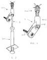
- FIG. 2is a perspective of the compression screw assembly and the biological material syringe
- FIG. 3is a perspective of the compression screw assembly and syringe in situ in a hip joint
- FIG. 4is a side view of the lag screw showing extended tang legs
- FIG. 5is a composite a side view of the lag screw including an end view of the leading end and the trailing end of the lag screw;
- FIG. 6is a side view, partially in section, of the lag screw
- FIG. 7is a composite of the side plate showing a side view a front view and a bore view
- FIG. 8is a side view of the syringe and adapter
- FIG. 9is a side view of the adapter showing the exit port
- FIG. 10is a longitudinal cross section of the compression screw assembly with the syringe and syringe adapter in place;
- FIG. 11is a longitudinal cross section of the lag screw and adapter showing the deployment of the tangs and location of the material discharge hole with the exit port.
- the implantable components 1constructed of stainless steel or titanium alloy, or other medically acceptable materials shown in FIG. 1 include the lag screw assembly 2 , side plate 3 , compression screw 4 and cortical screw 5 .
- FIG. 2illustrates the implantable assembly 1 , less compression screw 4 , with syringe adaptor 6 and syringe 7 assembled to deliver ortho-biologic material to the fracture site 8 , shown in
- FIG. 3 through the lag screw assembly 2also illustrates proper placement of the implant assembly with tang legs 9 and screw thread 11 located on the proximal side of fracture 8 and side plate 3 on the distal side of fracture 8 and ortho-biologic material discharge holes 12 in close proximity of the fracture 8 .
- the lag screw assembly 2contains two concentric bores, the tang clearance bore 28 and compression screw bore 16 which is threaded for engagement with compression screw 4 .
- An end cap 13is utilized to capture the tang body 14 within the clearance bore 18 .
- the end cap 13has a clearance bore through it to allow passage of a guide wire (not shown) during the installation of the lag screw assembly 2 .
- Ortho-biologic material discharge holes 12extend through the lag screw assembly 2 wall into the tang clearance bore 18 .
- the tang body 14shown in the deployed position, consists of a body with four integral tang legs 9 and a threaded bore 15 .
- tang 14In its non-deployed position, the entire tang is contained within lag screw assembly tang bore 18 . Deployment of tang 14 occurs when the tang 14 is translated toward the end cap 13 at which time tang legs 9 are forced out of tang exit holes 29 . Tang threaded bore 15 provides clearance for a guide wire during lag screw assembly 2 installation and instrument interface for tang 14 retraction.
- the non-threaded portion 10 of lag screw body 19in its preferred embodiment, has an octagonal cross section.
- the side plate 3in FIG. 7 , consists of a body 21 and barrel 20 .
- the body 21contains a through hole 22 for cortical screw 5 clearance.
- the barrel 20contains octagonal bore 23 which is sized to allow insertion of the compression screw octagonal body portion 10 and a sliding fit thereby allowing only translation without rotation.
- the compression screw 4inserts through side plate barrel 20 and threads into lag screw threaded bore 16 when the lag screw assembly octagonal body 10 is inserted into lag screw barrel octagonal barrel bore 23 . As the compression screw 4 is advanced, the head of compression screw 4 contacts and reacts with side plate 3 and forces lag screw assembly 2 to translate distally.
- the syringe adaptor 6in FIG. 8 , has a standard Leuer interface 31 at one end for connection to any standard syringe 7 .
- an external thread 26At the opposite end of the syringe adaptor 6 is an external thread 26 a exit port 25 and a shoulder 24 .
- An internal bore 27shown in FIG. 11 , runs the entire length of syringe adaptor 6 to the exit port 25 and intersects the exit port 25 but does not continue into the external thread 26 .
- the ortho-biological materialmay be selected from such groups of substances as bone cements, such as PMMA and other adhesives, BMP, bone morphogenic proteins, DBM, demineralized bone matrix, BOTOX and other viral vectors, any bone marrow aspirate, platelet rich plasma, composite ceramic hydroxyapatite, tricalcium phosphate, glass resin mixtures, resorbable highly purified polylacttides/polylactides-co-glycolides and others.
- the treating agentmay include hormonal, antibiotic, anti-cancer, or growth factor substances, among others.
Landscapes
- Health & Medical Sciences (AREA)
- Orthopedic Medicine & Surgery (AREA)
- Surgery (AREA)
- Life Sciences & Earth Sciences (AREA)
- Heart & Thoracic Surgery (AREA)
- Nuclear Medicine, Radiotherapy & Molecular Imaging (AREA)
- Engineering & Computer Science (AREA)
- Biomedical Technology (AREA)
- Neurology (AREA)
- Medical Informatics (AREA)
- Molecular Biology (AREA)
- Animal Behavior & Ethology (AREA)
- General Health & Medical Sciences (AREA)
- Public Health (AREA)
- Veterinary Medicine (AREA)
- Surgical Instruments (AREA)
Abstract
Description
This application claims the benefit of the filing date of U.S. Provisional Application No. 60/444,735 filed Feb. 3, 2003 under 35 U.S.C. 119(e).
1. Field of the Invention
This invention relates to the field of orthopedic surgery and, in particular, the treatment of fractures by implantation of bone screws for compression and medication.
2. Description of the Prior Art
The use of bone screws for stabilization and fixation of fractures is conventional. The use of lag screws for compression of fractures is also conventional, as shown by McCarthy, U.S. Pat. No. 5,514,138.
Lag screws and anchors with additional holding devices are taught by Bramlet, U.S. Pat. No. 5,849,004 and U.S. Pat. No. 6,443,954. These devices have curved talons which deploy from the interior of a cannulated body to increase the holding power.
Bone pins or screws have been used to access the interior of bones for application of diagnostic and structural components. For example, Kyle, U.S. Pat. No. 4,760,844, teaches the use of a cannulated screw for applying X-ray opaque dye and U.S. Pat. No. 4,653,489 teaches the use of a cannulated lag screw to apply polymethylmethacrylate (PMMA) or bone cement to the interior of a broken bone. In both these devices, the exuded material exits near the distal end of the screw which places the material in the immediate area of the screw threads.
What is lacking in the prior art is a lag screw with devices to increase the holding power of the screw and medicate the afflicted area while maintaining the ability to remove the devices and the screw.
A device for the treatment of a femoral neck trauma which includes basilar, mid-cervical and sub-cap fractures. The device is a compression screw assembly having a side plate, a compression screw and a cortical screw, which are implantable. A syringe adaptor instrument delivers ortho-biologic material to the fracture site through the lag screw. The lag screw assembly utilizes a cannulated screw with external threads and deployable tangs to anchor into the femoral head and is implanted in such a manner as to have the lag screw threads and tangs located on the opposite side of the fracture from the side plate. The distal shaft of the lag screw interfaces with the side plate in a manner which allows axial translation only. To deliver ortho-biologic material to the fracture site, the syringe adaptor instrument is inserted into the cannulated lag screw prior to the installation of the compression screw and the material is forced through it and out exit holes located circumferentially around the lag screw between the fracture site and the deployable tangs.
Thus, an objective of this invention is to repair fractures with a compression screw assembly exerting compression across of the fragments of the bone.
Another objective is to inject a biological material through the compression screw assembly into the area of the fracture to aid in recovery.
A further objective of this invention is to provide the lag screw assembly with a separation between the screw threads and the injection ports.
Yet another objective of this invention is to provide the injection assembly with a seal between the injection ports and the screw threads.
Other objectives and advantages of this invention will become apparent from the following description taken in conjunction with the accompanying drawings wherein are set forth, by way of illustration and example, certain embodiments of this invention. The drawings constitute a part of this specification and include exemplary embodiments of the present invention and illustrate various objects and features thereof.
The implantable components1, constructed of stainless steel or titanium alloy, or other medically acceptable materials shown inFIG. 1 include thelag screw assembly 2,side plate 3,compression screw 4 andcortical screw 5.FIG. 2 illustrates the implantable assembly1,less compression screw 4, withsyringe adaptor 6 andsyringe 7 assembled to deliver ortho-biologic material to the fracture site8, shown in
Thelag screw assembly 2, as shown inFIGS. 5 and 6 , contains two concentric bores, the tang clearance bore28 andcompression screw bore 16 which is threaded for engagement withcompression screw 4. Anend cap 13 is utilized to capture thetang body 14 within the clearance bore18. Theend cap 13 has a clearance bore through it to allow passage of a guide wire (not shown) during the installation of thelag screw assembly 2. Ortho-biologicmaterial discharge holes 12 extend through thelag screw assembly 2 wall into the tang clearance bore18. Thetang body 14, shown in the deployed position, consists of a body with fourintegral tang legs 9 and a threadedbore 15. In its non-deployed position, the entire tang is contained within lag screwassembly tang bore 18. Deployment oftang 14 occurs when thetang 14 is translated toward theend cap 13 at whichtime tang legs 9 are forced out oftang exit holes 29. Tang threadedbore 15 provides clearance for a guide wire duringlag screw assembly 2 installation and instrument interface fortang 14 retraction. Thenon-threaded portion 10 oflag screw body 19, in its preferred embodiment, has an octagonal cross section.
Theside plate 3, inFIG. 7 , consists of abody 21 andbarrel 20. Thebody 21 contains a throughhole 22 forcortical screw 5 clearance. Thebarrel 20 containsoctagonal bore 23 which is sized to allow insertion of the compression screwoctagonal body portion 10 and a sliding fit thereby allowing only translation without rotation. Thecompression screw 4 inserts throughside plate barrel 20 and threads into lag screw threaded bore16 when the lag screw assemblyoctagonal body 10 is inserted into lag screw barrel octagonal barrel bore23. As thecompression screw 4 is advanced, the head ofcompression screw 4 contacts and reacts withside plate 3 and forces lagscrew assembly 2 to translate distally. Since lag screw threads11 andtang legs 9 are engaged into bone on the proximal side of the fracture8 and theside plate 3 is located on the distal side of fracture8, fracture8 is reduced or compressed.Cortical screw 5 is threaded into bone throughclearance hole 22 preventing translation or rotation ofside plate 3 and since relative rotation is prevented as previously described betweenlag screw 2 andside plate 3 and thetang legs 9 are engaged in the bone of the femoral head, rotation of the femoral head and fracture is prevented.
Thesyringe adaptor 6, inFIG. 8 , has astandard Leuer interface 31 at one end for connection to anystandard syringe 7. At the opposite end of thesyringe adaptor 6 is an external thread26 aexit port 25 and ashoulder 24. Aninternal bore 27, shown inFIG. 11 , runs the entire length ofsyringe adaptor 6 to theexit port 25 and intersects theexit port 25 but does not continue into theexternal thread 26. After implanting the implant assembly1 less thecompression screw 4 thesyringe adaptor 6 is inserted through side plate barrel bore23, through lag screw assembly compression screw bore16, through lag screw assembly tang clearance bore18. Theexternal thread 26 ofsyringe adaptor 6 is then engaged into threaded bore15 oftang body 14 and advanced untilshoulder 24 ofsyringe adaptor 6 makes contact with lagscrew assembly shoulder 17. At thispoint syringe 7 is attached tosyringe adaptor 6 by means of theLeuer interface 31 ofFIG. 10 or any other connector.
To introduce the ortho-biologic material,plunger 30 ofsyringe 7 is depressed forcing the material through theinternal bore 27 ofsyringe adaptor 6 and out the syringe adaptorfluid exit port 25 into the lag screw assembly tang clearance bore18. For example, the ortho-biological material may be selected from such groups of substances as bone cements, such as PMMA and other adhesives, BMP, bone morphogenic proteins, DBM, demineralized bone matrix, BOTOX and other viral vectors, any bone marrow aspirate, platelet rich plasma, composite ceramic hydroxyapatite, tricalcium phosphate, glass resin mixtures, resorbable highly purified polylacttides/polylactides-co-glycolides and others. The treating agent may include hormonal, antibiotic, anti-cancer, or growth factor substances, among others.
Withtang body 14 having a close fit in lag screw assembly tang clearance bore18 and syringe adaptorexternal thread 26 engaged in tang bodyinternal thread 15 andsyringe adaptor shoulder 24 in contact with lagscrew assembly shoulder 17, the fluid is forced to exit through lag screw assembly ortho-biologic material exit holes12 and into the proximity of the fracture8. After, the material is delivered, thesyringe adaptor 6 is removed andcompression screw 4 is engaged and the fracture8 is compressed/reduced as previously described.
It will be understood that various modifications may be made without departing from the spirit and scope of the invention. Accordingly, it is to be understood that the invention is not to be limited by the specific illustrated embodiment but only by the scope of the appended claims.
Claims (10)
1. A compression screw assembly for delivery of an ortho-biological material to a fracture site comprising a lag screw, a side plate, an elongated adapter, and a compression screw, said lag screw having an elongated body with a leading end, a distal end, and a longitudinal bore, external threads on said leading end for engaging a bone proximal to a fracture site, said leading end of said lag screw having at least one tang exit hole, a tang body movably disposed in said longitudinal bore and having at least one tang leg mounted to a first end, said tang leg adapted to translate through said at least one tang exit hole upon movement of said tang body, and a second end of said tang body having internal screw threads adapted to seal said tang body, said distal end of said lag screw adapted to extend distally of said fracture site, a first connector on said distal end, at least one discharge hole in said elongated body between said external threads and said distal end, said side plate having a body with a distal surface and a proximal surface, an aperture in said plate sized to accommodated said distal end of said lag screw whereby said side plate is adapted to slide along said elongated body and exerts compressive force between an enlarged head and said external threads, said adapter being of a size to telescope within said through bore of said elongated body, said elongated adapter having a bore extending from one end and terminating in a fluid exit port near the other end, said other end beyond said fluid exit port having external screw threads adapted to engage said internal screw threads in said tang body, said one end adapted to be connected with a syringe and said fluid exit port adapted to register with said discharge hole in said elongated body whereby ortho-biological material may be delivered to a fracture site, said compression screw having said enlarged head on one end and a second connector on the other end, said second connector on said compression screw adapted to mate with said first connector whereby said compression screw exerts a compressive force between said enlarged head and said external threads reducing the fracture.
2. A compression screw assembly ofclaim 1 comprising said distal end of said elongated body shaped for non-rotational movement and said aperture shaped for sliding longitudinally along said body.
3. A compression screw assembly ofclaim 2 comprising a barrel on said proximal surface of said side plate surrounding said aperture.
4. A compression screw assembly ofclaim 1 comprising a barrel on said proximal surface of said side plate surrounding said aperture.
5. A compression screw assembly ofclaim 4 comprising a cortical screw hole in said side plate.
6. A compression screw assembly ofclaim 1 comprising a cortical screw hole in said side plate.
7. A compression screw assembly kit for delivery of an ortho-biological material to a fracture site comprising a lag screw, a compression screw, a side plate, and an adapter, said lag screw having external threads and at least one tang exit hole at one end adapted to fix said lag screw in a bone proximal to a fracture site, a bore extending from said one end to the other end, said bore having internal threads in said other end, a circumferential seal in said bore spaced distally from said external threads, a discharge hole in said bore between said external threads and said other end, said side plate having an aperture adapted to telescope with said other end of said lag screw, said adapter having one end, a connector on the other end and a bore from said connector terminating in a fluid exit port near said one end, said adapter having a circumferential shoulder between said fluid exit port and said connector, a movable tang body in said bore between said discharge hole and said external threads, said tang body having at least one tang lea on one end and a seal on the other end, said one end of said adapter sized to engage said seal on said tang body whereby upon insertion of said adapter into said lag screw said one end of said adapter engages said seal in said tang body and said tang body is moved within said bore to register said fluid exit port and said discharge hole thereby extending said tang leg from said tang exit hole, said compression screw having an enlarged head on one end and external threads on the other end, said connector sized to pass through said aperture of said side plate and engage said internal threads in said through bore of said lag screw, said head adapted to engage said body of said side plate, whereby said lag screw may be threadably fixed in a bone proximal to a fracture site, said adapter is insertable into said lag screw with said shoulder engagable with said seal and said fluid exit port registered with said discharge hole, said connector adapted to mate with a source of ortho-biological material for permitting said ortho-biological material to flow through said adapter and out the discharge hole in the vicinity of said fracture site, said adapter being removable, said side plate adapted to be telescoped with said lag screw and said compression screw being insertable through said aperture for threadable engagement with said internal threads to apply compressive force between said side plate and said lag screw to reduce said fracture.
8. A compression screw assembly kit ofclaim 7 comprising said seal in said tang body being threads, said one end of said adapter having threads whereby threadably engaging said adapter threads and said tang body threads forms a seal.
9. A compression screw assembly for reduction of a fracture comprising a lag screw, an adapter, and a compression screw, said lag screw having an elongated body with a leading end, a distal end, and a longitudinal bore, external threads on said leading end for engaging a bone proximal to a fracture site, a tang body movably mounted in said longitudinal bore, said tang body having at least one tang leg, at least one tang exit hole formed in said leading end communicating with said longitudinal bore, said adapter sized to telescope through said longitudinal bore and engage and move said tang body toward said leading end and said tang leg extends through said tang exit hole as said tang body is moved toward said leading end, said adapter having a bore extending from one end and terminating in a fluid exit port near the other end, said distal end of said lag screw adjustably connected to one end of a compression screw having an enlarged head on the other end, said compression screw adapted to adjust the interval between said external threads and said enlarged head whereby said compression screw exerts a compressive force between said enlarged head and said external threads reducing the fracture.
10. A compression screw assembly ofclaim 9 comprising an end cap mounted in said leading end of said longitudinal bore.
Priority Applications (1)
| Application Number | Priority Date | Filing Date | Title |
|---|---|---|---|
| US10/766,666US7118572B2 (en) | 2003-02-03 | 2004-01-27 | Femoral neck compression screw system with ortho-biologic material delivery capability |
Applications Claiming Priority (2)
| Application Number | Priority Date | Filing Date | Title |
|---|---|---|---|
| US44473503P | 2003-02-03 | 2003-02-03 | |
| US10/766,666US7118572B2 (en) | 2003-02-03 | 2004-01-27 | Femoral neck compression screw system with ortho-biologic material delivery capability |
Publications (2)
| Publication Number | Publication Date |
|---|---|
| US20040193162A1 US20040193162A1 (en) | 2004-09-30 |
| US7118572B2true US7118572B2 (en) | 2006-10-10 |
Family
ID=32850917
Family Applications (1)
| Application Number | Title | Priority Date | Filing Date |
|---|---|---|---|
| US10/766,666Expired - Fee RelatedUS7118572B2 (en) | 2003-02-03 | 2004-01-27 | Femoral neck compression screw system with ortho-biologic material delivery capability |
Country Status (2)
| Country | Link |
|---|---|
| US (1) | US7118572B2 (en) |
| WO (1) | WO2004069094A2 (en) |
Cited By (40)
| Publication number | Priority date | Publication date | Assignee | Title |
|---|---|---|---|---|
| US20050159749A1 (en)* | 2004-01-16 | 2005-07-21 | Expanding Orthopedics, Inc. | Bone fracture treatment devices and methods of their use |
| US20050177158A1 (en)* | 2004-02-09 | 2005-08-11 | Doubler Robert L. | Intramedullary screw and tang for orthopedic surgery |
| US20080086131A1 (en)* | 2006-10-06 | 2008-04-10 | Depuy Spine, Inc. | Bone screw fixation |
| US7476253B1 (en)* | 2004-08-11 | 2009-01-13 | Biomet Manufacturing Corporation | Humeral head preserving implant |
| US20100217265A1 (en)* | 2009-02-24 | 2010-08-26 | National Yang-Ming University | Anti-subsidence dynamic hip screw |
| US20110137313A1 (en)* | 2008-08-12 | 2011-06-09 | Tantum Ag | Short pin for taking care of epiphysis fractures |
| US8282675B2 (en) | 2008-01-25 | 2012-10-09 | Depuy Spine, Inc. | Anti-backout mechanism |
| US8535322B1 (en)* | 2012-11-07 | 2013-09-17 | Roy Y. Powlan | Hip nail and inertial insertion tooling |
| WO2014114968A1 (en)* | 2013-01-28 | 2014-07-31 | Hossam Abdel Salam El Sayed Mohamed | Bone fixation device |
| US9314283B2 (en) | 2011-11-18 | 2016-04-19 | DePuy Synthes Products, Inc. | Femoral neck fracture implant |
| US9522070B2 (en) | 2013-03-07 | 2016-12-20 | Interventional Spine, Inc. | Intervertebral implant |
| US9839530B2 (en) | 2007-06-26 | 2017-12-12 | DePuy Synthes Products, Inc. | Highly lordosed fusion cage |
| US9883951B2 (en) | 2012-08-30 | 2018-02-06 | Interventional Spine, Inc. | Artificial disc |
| US9895236B2 (en) | 2010-06-24 | 2018-02-20 | DePuy Synthes Products, Inc. | Enhanced cage insertion assembly |
| US9913727B2 (en) | 2015-07-02 | 2018-03-13 | Medos International Sarl | Expandable implant |
| US9931223B2 (en) | 2008-04-05 | 2018-04-03 | DePuy Synthes Products, Inc. | Expandable intervertebral implant |
| US9993349B2 (en) | 2002-06-27 | 2018-06-12 | DePuy Synthes Products, Inc. | Intervertebral disc |
| US10058433B2 (en) | 2012-07-26 | 2018-08-28 | DePuy Synthes Products, Inc. | Expandable implant |
| US10390963B2 (en) | 2006-12-07 | 2019-08-27 | DePuy Synthes Products, Inc. | Intervertebral implant |
| US10398563B2 (en) | 2017-05-08 | 2019-09-03 | Medos International Sarl | Expandable cage |
| US10433977B2 (en) | 2008-01-17 | 2019-10-08 | DePuy Synthes Products, Inc. | Expandable intervertebral implant and associated method of manufacturing the same |
| US10500062B2 (en) | 2009-12-10 | 2019-12-10 | DePuy Synthes Products, Inc. | Bellows-like expandable interbody fusion cage |
| US10537436B2 (en) | 2016-11-01 | 2020-01-21 | DePuy Synthes Products, Inc. | Curved expandable cage |
| US10548741B2 (en) | 2010-06-29 | 2020-02-04 | DePuy Synthes Products, Inc. | Distractible intervertebral implant |
| US10888433B2 (en) | 2016-12-14 | 2021-01-12 | DePuy Synthes Products, Inc. | Intervertebral implant inserter and related methods |
| US10940016B2 (en) | 2017-07-05 | 2021-03-09 | Medos International Sarl | Expandable intervertebral fusion cage |
| US11344424B2 (en) | 2017-06-14 | 2022-05-31 | Medos International Sarl | Expandable intervertebral implant and related methods |
| US11426290B2 (en) | 2015-03-06 | 2022-08-30 | DePuy Synthes Products, Inc. | Expandable intervertebral implant, system, kit and method |
| US11426286B2 (en) | 2020-03-06 | 2022-08-30 | Eit Emerging Implant Technologies Gmbh | Expandable intervertebral implant |
| US11446156B2 (en) | 2018-10-25 | 2022-09-20 | Medos International Sarl | Expandable intervertebral implant, inserter instrument, and related methods |
| US11452607B2 (en) | 2010-10-11 | 2022-09-27 | DePuy Synthes Products, Inc. | Expandable interspinous process spacer implant |
| US11510788B2 (en) | 2016-06-28 | 2022-11-29 | Eit Emerging Implant Technologies Gmbh | Expandable, angularly adjustable intervertebral cages |
| US11596523B2 (en) | 2016-06-28 | 2023-03-07 | Eit Emerging Implant Technologies Gmbh | Expandable and angularly adjustable articulating intervertebral cages |
| US11612491B2 (en) | 2009-03-30 | 2023-03-28 | DePuy Synthes Products, Inc. | Zero profile spinal fusion cage |
| US11752009B2 (en) | 2021-04-06 | 2023-09-12 | Medos International Sarl | Expandable intervertebral fusion cage |
| US11850160B2 (en) | 2021-03-26 | 2023-12-26 | Medos International Sarl | Expandable lordotic intervertebral fusion cage |
| US11911287B2 (en) | 2010-06-24 | 2024-02-27 | DePuy Synthes Products, Inc. | Lateral spondylolisthesis reduction cage |
| USRE49973E1 (en) | 2013-02-28 | 2024-05-21 | DePuy Synthes Products, Inc. | Expandable intervertebral implant, system, kit and method |
| US12090064B2 (en) | 2022-03-01 | 2024-09-17 | Medos International Sarl | Stabilization members for expandable intervertebral implants, and related systems and methods |
| US12440346B2 (en) | 2023-03-31 | 2025-10-14 | DePuy Synthes Products, Inc. | Expandable intervertebral implant |
Families Citing this family (32)
| Publication number | Priority date | Publication date | Assignee | Title |
|---|---|---|---|---|
| US7780710B2 (en)* | 2004-01-23 | 2010-08-24 | Depuy Products, Inc. | System for stabilization of fractures of convex articular bone surfaces including subchondral support structure |
| AU2011202774B2 (en)* | 2004-01-23 | 2012-02-02 | Hand Innovations, Llc | System for stabilization of fractures of convex articular bone surfaces including subchondral support structure |
| US20060036248A1 (en)* | 2004-07-01 | 2006-02-16 | Ferrante Joseph M | Fixation elements |
| US20080221623A1 (en)* | 2005-10-17 | 2008-09-11 | Gooch Hubert L | Systems and Methods for the Medical Treatment of Structural Tissue |
| US8926675B2 (en)* | 2006-04-11 | 2015-01-06 | Biomet Manufacturing, Llc | Contoured bone plate |
| US20080086136A1 (en)* | 2006-08-30 | 2008-04-10 | Bednar Drew A | Percutaneous hip system |
| KR100841432B1 (en)* | 2007-01-03 | 2008-06-25 | 유앤아이 주식회사 | Fixing Screw for Femur Fracture Treatment |
| KR101504964B1 (en)* | 2007-04-27 | 2015-03-30 | 신세스 게엠바하 | Implant devices constructed with metalic and polymeric components |
| SE533303C2 (en)* | 2007-07-24 | 2010-08-17 | Henrik Hansson | Device for fixing bone fragments in case of bone fracture |
| US8740954B2 (en)* | 2007-12-19 | 2014-06-03 | Integral Spine Solutions, Inc. | Device and method for orthopedic fracture fixation |
| SE532211C2 (en) | 2008-03-27 | 2009-11-17 | Swemac Innovation Ab | Device for fixing bone fragments in case of bone fracture |
| US8182484B2 (en)* | 2008-04-21 | 2012-05-22 | Depuy Products, Inc. | Orthopaedic trauma hip screw assembly |
| KR20110033199A (en)* | 2008-06-19 | 2011-03-30 | 신세스 게엠바하 | Bone Screw Percussion Augmented Implants, Systems and Technologies |
| US8328806B2 (en) | 2008-06-24 | 2012-12-11 | Extremity Medical, Llc | Fixation system, an intramedullary fixation assembly and method of use |
| US9044282B2 (en) | 2008-06-24 | 2015-06-02 | Extremity Medical Llc | Intraosseous intramedullary fixation assembly and method of use |
| US8313487B2 (en) | 2008-06-24 | 2012-11-20 | Extremity Medical Llc | Fixation system, an intramedullary fixation assembly and method of use |
| US8303589B2 (en) | 2008-06-24 | 2012-11-06 | Extremity Medical Llc | Fixation system, an intramedullary fixation assembly and method of use |
| US9017329B2 (en) | 2008-06-24 | 2015-04-28 | Extremity Medical, Llc | Intramedullary fixation assembly and method of use |
| US9289220B2 (en) | 2008-06-24 | 2016-03-22 | Extremity Medical Llc | Intramedullary fixation assembly and method of use |
| US8945184B2 (en)* | 2009-03-13 | 2015-02-03 | Spinal Simplicity Llc. | Interspinous process implant and fusion cage spacer |
| ES2552380T3 (en) | 2009-07-01 | 2015-11-27 | Biedermann Technologies Gmbh & Co. Kg | Instruments for use with a bone anchor with closure element |
| BR112012002215B1 (en)* | 2009-09-14 | 2020-06-02 | Synthes Gmbh | HUMAN HEAD FIXATION DEVICE FOR BONES WITH OSTEOPOROSIS. |
| US9675393B2 (en) | 2011-09-22 | 2017-06-13 | DePuy Synthes Products, Inc. | Shortening palm screw |
| US9241806B2 (en) | 2011-09-26 | 2016-01-26 | Globus Medical, Inc. | Flexible anchoring and fusion devices and methods of using the same |
| WO2014045103A1 (en)* | 2012-09-20 | 2014-03-27 | Mjp Innovations Ag | Hip implant |
| JP6420787B2 (en)* | 2015-04-22 | 2018-11-07 | 学校法人順天堂 | Fracture fixation device |
| US10881436B2 (en) | 2017-10-27 | 2021-01-05 | Wright Medical Technology, Inc. | Implant with intramedullary portion and offset extramedullary portion |
| US11918261B2 (en)* | 2019-04-12 | 2024-03-05 | Stryker European Operations Limited | Locking system for femoral neck fracture fixation |
| CN112716586B (en)* | 2021-01-25 | 2023-11-03 | 李晖 | Intramedullary fixing device for femur fracture |
| DE102021004940A1 (en) | 2021-10-01 | 2023-04-06 | Westsächsische Hochschule Zwickau, Körperschaft des öffentlichen Rechts | Fracture treatment device |
| US12133664B2 (en) | 2022-12-13 | 2024-11-05 | Spinal Simplicity, Llc | Medical implant |
| WO2024258903A2 (en)* | 2023-06-12 | 2024-12-19 | Mjp Innovations, Inc | Femoral neck support structure, system, and method of use |
Citations (7)
| Publication number | Priority date | Publication date | Assignee | Title |
|---|---|---|---|---|
| US3791380A (en)* | 1971-12-13 | 1974-02-12 | G Dawidowski | Method and apparatus of immobilizing a fractured femur |
| US4653489A (en) | 1984-04-02 | 1987-03-31 | Tronzo Raymond G | Fenestrated hip screw and method of augmented fixation |
| US4760844A (en) | 1986-03-21 | 1988-08-02 | Ace Medical Company | Cannulated screw dye injector |
| US5514138A (en) | 1991-02-08 | 1996-05-07 | Pfizer Inc. | Connector having a stop member |
| US5849004A (en) | 1996-07-17 | 1998-12-15 | Bramlet; Dale G. | Surgical anchor |
| US6183474B1 (en)* | 1996-03-13 | 2001-02-06 | Dale G. Bramlet | Surgical fastener assembly |
| US6443954B1 (en) | 2001-04-24 | 2002-09-03 | Dale G. Bramlet | Femoral nail intramedullary system |
- 2004
- 2004-01-27USUS10/766,666patent/US7118572B2/ennot_activeExpired - Fee Related
- 2004-01-28WOPCT/US2004/002480patent/WO2004069094A2/enactiveApplication Filing
Patent Citations (7)
| Publication number | Priority date | Publication date | Assignee | Title |
|---|---|---|---|---|
| US3791380A (en)* | 1971-12-13 | 1974-02-12 | G Dawidowski | Method and apparatus of immobilizing a fractured femur |
| US4653489A (en) | 1984-04-02 | 1987-03-31 | Tronzo Raymond G | Fenestrated hip screw and method of augmented fixation |
| US4760844A (en) | 1986-03-21 | 1988-08-02 | Ace Medical Company | Cannulated screw dye injector |
| US5514138A (en) | 1991-02-08 | 1996-05-07 | Pfizer Inc. | Connector having a stop member |
| US6183474B1 (en)* | 1996-03-13 | 2001-02-06 | Dale G. Bramlet | Surgical fastener assembly |
| US5849004A (en) | 1996-07-17 | 1998-12-15 | Bramlet; Dale G. | Surgical anchor |
| US6443954B1 (en) | 2001-04-24 | 2002-09-03 | Dale G. Bramlet | Femoral nail intramedullary system |
Cited By (87)
| Publication number | Priority date | Publication date | Assignee | Title |
|---|---|---|---|---|
| US9993349B2 (en) | 2002-06-27 | 2018-06-12 | DePuy Synthes Products, Inc. | Intervertebral disc |
| US7828802B2 (en) | 2004-01-16 | 2010-11-09 | Expanding Orthopedics, Inc. | Bone fracture treatment devices and methods of their use |
| US20050159749A1 (en)* | 2004-01-16 | 2005-07-21 | Expanding Orthopedics, Inc. | Bone fracture treatment devices and methods of their use |
| US20050177158A1 (en)* | 2004-02-09 | 2005-08-11 | Doubler Robert L. | Intramedullary screw and tang for orthopedic surgery |
| US8157801B2 (en)* | 2004-02-09 | 2012-04-17 | Doubler Robert L | Intramedullary screw and tang for orthopedic surgery |
| US7476253B1 (en)* | 2004-08-11 | 2009-01-13 | Biomet Manufacturing Corporation | Humeral head preserving implant |
| US8361130B2 (en)* | 2006-10-06 | 2013-01-29 | Depuy Spine, Inc. | Bone screw fixation |
| US20080086131A1 (en)* | 2006-10-06 | 2008-04-10 | Depuy Spine, Inc. | Bone screw fixation |
| US9119676B2 (en) | 2006-10-06 | 2015-09-01 | DePuy Synthes Products, Inc. | Bone screw fixation |
| US11642229B2 (en) | 2006-12-07 | 2023-05-09 | DePuy Synthes Products, Inc. | Intervertebral implant |
| US11432942B2 (en) | 2006-12-07 | 2022-09-06 | DePuy Synthes Products, Inc. | Intervertebral implant |
| US11660206B2 (en) | 2006-12-07 | 2023-05-30 | DePuy Synthes Products, Inc. | Intervertebral implant |
| US10390963B2 (en) | 2006-12-07 | 2019-08-27 | DePuy Synthes Products, Inc. | Intervertebral implant |
| US11712345B2 (en) | 2006-12-07 | 2023-08-01 | DePuy Synthes Products, Inc. | Intervertebral implant |
| US10398566B2 (en) | 2006-12-07 | 2019-09-03 | DePuy Synthes Products, Inc. | Intervertebral implant |
| US11497618B2 (en) | 2006-12-07 | 2022-11-15 | DePuy Synthes Products, Inc. | Intervertebral implant |
| US10583015B2 (en) | 2006-12-07 | 2020-03-10 | DePuy Synthes Products, Inc. | Intervertebral implant |
| US11273050B2 (en) | 2006-12-07 | 2022-03-15 | DePuy Synthes Products, Inc. | Intervertebral implant |
| US9839530B2 (en) | 2007-06-26 | 2017-12-12 | DePuy Synthes Products, Inc. | Highly lordosed fusion cage |
| US10973652B2 (en) | 2007-06-26 | 2021-04-13 | DePuy Synthes Products, Inc. | Highly lordosed fusion cage |
| US11622868B2 (en) | 2007-06-26 | 2023-04-11 | DePuy Synthes Products, Inc. | Highly lordosed fusion cage |
| US10449058B2 (en) | 2008-01-17 | 2019-10-22 | DePuy Synthes Products, Inc. | Expandable intervertebral implant and associated method of manufacturing the same |
| US10433977B2 (en) | 2008-01-17 | 2019-10-08 | DePuy Synthes Products, Inc. | Expandable intervertebral implant and associated method of manufacturing the same |
| US11737881B2 (en) | 2008-01-17 | 2023-08-29 | DePuy Synthes Products, Inc. | Expandable intervertebral implant and associated method of manufacturing the same |
| US8282675B2 (en) | 2008-01-25 | 2012-10-09 | Depuy Spine, Inc. | Anti-backout mechanism |
| US11701234B2 (en) | 2008-04-05 | 2023-07-18 | DePuy Synthes Products, Inc. | Expandable intervertebral implant |
| US11712342B2 (en) | 2008-04-05 | 2023-08-01 | DePuy Synthes Products, Inc. | Expandable intervertebral implant |
| US11617655B2 (en) | 2008-04-05 | 2023-04-04 | DePuy Synthes Products, Inc. | Expandable intervertebral implant |
| US11707359B2 (en) | 2008-04-05 | 2023-07-25 | DePuy Synthes Products, Inc. | Expandable intervertebral implant |
| US9993350B2 (en) | 2008-04-05 | 2018-06-12 | DePuy Synthes Products, Inc. | Expandable intervertebral implant |
| US11602438B2 (en) | 2008-04-05 | 2023-03-14 | DePuy Synthes Products, Inc. | Expandable intervertebral implant |
| US9931223B2 (en) | 2008-04-05 | 2018-04-03 | DePuy Synthes Products, Inc. | Expandable intervertebral implant |
| US12023255B2 (en) | 2008-04-05 | 2024-07-02 | DePuy Synthes Products, Inc. | Expandable inter vertebral implant |
| US10449056B2 (en) | 2008-04-05 | 2019-10-22 | DePuy Synthes Products, Inc. | Expandable intervertebral implant |
| US11712341B2 (en) | 2008-04-05 | 2023-08-01 | DePuy Synthes Products, Inc. | Expandable intervertebral implant |
| US12011361B2 (en) | 2008-04-05 | 2024-06-18 | DePuy Synthes Products, Inc. | Expandable intervertebral implant |
| US8486071B2 (en)* | 2008-08-12 | 2013-07-16 | Tantum Ag | Short pin for taking care of epiphysis fractures |
| US20110137313A1 (en)* | 2008-08-12 | 2011-06-09 | Tantum Ag | Short pin for taking care of epiphysis fractures |
| US20100217265A1 (en)* | 2009-02-24 | 2010-08-26 | National Yang-Ming University | Anti-subsidence dynamic hip screw |
| US11612491B2 (en) | 2009-03-30 | 2023-03-28 | DePuy Synthes Products, Inc. | Zero profile spinal fusion cage |
| US12097124B2 (en) | 2009-03-30 | 2024-09-24 | DePuy Synthes Products, Inc. | Zero profile spinal fusion cage |
| US11607321B2 (en) | 2009-12-10 | 2023-03-21 | DePuy Synthes Products, Inc. | Bellows-like expandable interbody fusion cage |
| US10500062B2 (en) | 2009-12-10 | 2019-12-10 | DePuy Synthes Products, Inc. | Bellows-like expandable interbody fusion cage |
| US10966840B2 (en) | 2010-06-24 | 2021-04-06 | DePuy Synthes Products, Inc. | Enhanced cage insertion assembly |
| US11872139B2 (en) | 2010-06-24 | 2024-01-16 | DePuy Synthes Products, Inc. | Enhanced cage insertion assembly |
| US12318304B2 (en) | 2010-06-24 | 2025-06-03 | DePuy Synthes Products, Inc. | Lateral spondylolisthesis reduction cage |
| US11911287B2 (en) | 2010-06-24 | 2024-02-27 | DePuy Synthes Products, Inc. | Lateral spondylolisthesis reduction cage |
| US9895236B2 (en) | 2010-06-24 | 2018-02-20 | DePuy Synthes Products, Inc. | Enhanced cage insertion assembly |
| US11654033B2 (en) | 2010-06-29 | 2023-05-23 | DePuy Synthes Products, Inc. | Distractible intervertebral implant |
| US10548741B2 (en) | 2010-06-29 | 2020-02-04 | DePuy Synthes Products, Inc. | Distractible intervertebral implant |
| US11452607B2 (en) | 2010-10-11 | 2022-09-27 | DePuy Synthes Products, Inc. | Expandable interspinous process spacer implant |
| US9662156B2 (en) | 2011-11-18 | 2017-05-30 | DePuy Synthes Products, Inc. | Femoral neck fracture implant |
| US10507048B2 (en) | 2011-11-18 | 2019-12-17 | DePuy Synthes Products, Inc. | Femoral neck fracture implant |
| US9314283B2 (en) | 2011-11-18 | 2016-04-19 | DePuy Synthes Products, Inc. | Femoral neck fracture implant |
| US9999453B2 (en) | 2011-11-18 | 2018-06-19 | DePuy Synthes Products, Inc. | Femoral neck fracture implant |
| US10058433B2 (en) | 2012-07-26 | 2018-08-28 | DePuy Synthes Products, Inc. | Expandable implant |
| US9883951B2 (en) | 2012-08-30 | 2018-02-06 | Interventional Spine, Inc. | Artificial disc |
| US8535322B1 (en)* | 2012-11-07 | 2013-09-17 | Roy Y. Powlan | Hip nail and inertial insertion tooling |
| WO2014114968A1 (en)* | 2013-01-28 | 2014-07-31 | Hossam Abdel Salam El Sayed Mohamed | Bone fixation device |
| US9486259B2 (en) | 2013-01-28 | 2016-11-08 | Hossam Abdel Salam EL Sayad Mohamed | Bone fixation device |
| USRE49973E1 (en) | 2013-02-28 | 2024-05-21 | DePuy Synthes Products, Inc. | Expandable intervertebral implant, system, kit and method |
| US10413422B2 (en) | 2013-03-07 | 2019-09-17 | DePuy Synthes Products, Inc. | Intervertebral implant |
| US11497619B2 (en) | 2013-03-07 | 2022-11-15 | DePuy Synthes Products, Inc. | Intervertebral implant |
| US9522070B2 (en) | 2013-03-07 | 2016-12-20 | Interventional Spine, Inc. | Intervertebral implant |
| US11850164B2 (en) | 2013-03-07 | 2023-12-26 | DePuy Synthes Products, Inc. | Intervertebral implant |
| US11426290B2 (en) | 2015-03-06 | 2022-08-30 | DePuy Synthes Products, Inc. | Expandable intervertebral implant, system, kit and method |
| US9913727B2 (en) | 2015-07-02 | 2018-03-13 | Medos International Sarl | Expandable implant |
| US11510788B2 (en) | 2016-06-28 | 2022-11-29 | Eit Emerging Implant Technologies Gmbh | Expandable, angularly adjustable intervertebral cages |
| US11596522B2 (en) | 2016-06-28 | 2023-03-07 | Eit Emerging Implant Technologies Gmbh | Expandable and angularly adjustable intervertebral cages with articulating joint |
| US12433757B2 (en) | 2016-06-28 | 2025-10-07 | Eit Emerging Implant Technologies Gmbh | Expandable, angularly adjustable and articulating intervertebral cages |
| US12390343B2 (en) | 2016-06-28 | 2025-08-19 | Eit Emerging Implant Technologies Gmbh | Expandable, angularly adjustable intervertebral cages |
| US11596523B2 (en) | 2016-06-28 | 2023-03-07 | Eit Emerging Implant Technologies Gmbh | Expandable and angularly adjustable articulating intervertebral cages |
| US10537436B2 (en) | 2016-11-01 | 2020-01-21 | DePuy Synthes Products, Inc. | Curved expandable cage |
| US10888433B2 (en) | 2016-12-14 | 2021-01-12 | DePuy Synthes Products, Inc. | Intervertebral implant inserter and related methods |
| US11446155B2 (en) | 2017-05-08 | 2022-09-20 | Medos International Sarl | Expandable cage |
| US10398563B2 (en) | 2017-05-08 | 2019-09-03 | Medos International Sarl | Expandable cage |
| US12427031B2 (en) | 2017-05-08 | 2025-09-30 | Medos International Sarl | Expandable cage |
| US11344424B2 (en) | 2017-06-14 | 2022-05-31 | Medos International Sarl | Expandable intervertebral implant and related methods |
| US10940016B2 (en) | 2017-07-05 | 2021-03-09 | Medos International Sarl | Expandable intervertebral fusion cage |
| US11446156B2 (en) | 2018-10-25 | 2022-09-20 | Medos International Sarl | Expandable intervertebral implant, inserter instrument, and related methods |
| US11806245B2 (en) | 2020-03-06 | 2023-11-07 | Eit Emerging Implant Technologies Gmbh | Expandable intervertebral implant |
| US11426286B2 (en) | 2020-03-06 | 2022-08-30 | Eit Emerging Implant Technologies Gmbh | Expandable intervertebral implant |
| US11850160B2 (en) | 2021-03-26 | 2023-12-26 | Medos International Sarl | Expandable lordotic intervertebral fusion cage |
| US11752009B2 (en) | 2021-04-06 | 2023-09-12 | Medos International Sarl | Expandable intervertebral fusion cage |
| US12023258B2 (en) | 2021-04-06 | 2024-07-02 | Medos International Sarl | Expandable intervertebral fusion cage |
| US12090064B2 (en) | 2022-03-01 | 2024-09-17 | Medos International Sarl | Stabilization members for expandable intervertebral implants, and related systems and methods |
| US12440346B2 (en) | 2023-03-31 | 2025-10-14 | DePuy Synthes Products, Inc. | Expandable intervertebral implant |
Also Published As
| Publication number | Publication date |
|---|---|
| WO2004069094A3 (en) | 2006-12-14 |
| US20040193162A1 (en) | 2004-09-30 |
| WO2004069094A2 (en) | 2004-08-19 |
Similar Documents
| Publication | Publication Date | Title |
|---|---|---|
| US7118572B2 (en) | Femoral neck compression screw system with ortho-biologic material delivery capability | |
| US8808337B2 (en) | Method and device for delivering medicine to bone | |
| US7544196B2 (en) | System and kit for delivery of restorative materials | |
| US5035697A (en) | Orthopedic medullary nail | |
| AU2012267730B2 (en) | Instruments and devices for subchondral joint repair | |
| US12285198B2 (en) | Device for the local application of and/or for flushing with pharmaceutical fluids | |
| US10022165B2 (en) | Orthopedic fastener device | |
| US6203544B1 (en) | Fixation element | |
| Caja et al. | Hydroxyapatite coated external fixation pins: an experimental study. | |
| US20040049192A1 (en) | Osteosynthetic apparatus | |
| EP2882361A1 (en) | Devices for delivery of medicine to bone | |
| US9480506B2 (en) | Compression device for interlocking compression nailing systems and method of use | |
| Durall et al. | Interlocking nail stabilisation of humeral fractures. Initial experience in seven clinical cases | |
| WO2015137911A1 (en) | Orthopedic fastener device | |
| RU2762949C1 (en) | Long bone fracture reposition system | |
| AU2015277489B2 (en) | High pressure remote delivery system for cement and methods of use | |
| Mirzasadeghi et al. | Intramedullary cement osteosynthesis (IMCO): a pilot study in sheep | |
| RU2359634C2 (en) | Method of intramedullary nail blocking | |
| WO2018067085A2 (en) | Diaphyseal and arthrodesis endoprosthesis system | |
| US20090306663A1 (en) | Bone Fixation Device | |
| RU2656766C1 (en) | Method for treatment of periprosthetic fracture of the tibia in osteoporosis | |
| RU2389441C1 (en) | Method for blocking intramedullary fixation device in treatment of tibial fractures | |
| RU155660U1 (en) | INTRAMEDOLLARY DEVICE FOR OSTEOSYNTHESIS IN SQUARE FRACTURES OF THE PROXIMAL FEM DIVISION | |
| UA55066A (en) | Intramedullary metallopolymeric fixing lock-out element "ukrfix" | |
| RO117065B1 (en) | Apparatus and clinical method for femoral or tibial distraction |
Legal Events
| Date | Code | Title | Description |
|---|---|---|---|
| AS | Assignment | Owner name:ORTHOPEDIC DESIGNS, INC., FLORIDA Free format text:ASSIGNMENT OF ASSIGNORS INTEREST;ASSIGNORS:BRAMLET, DALE G.;STERGHOS, PETER M.;REEL/FRAME:014944/0811 Effective date:20040122 | |
| FPAY | Fee payment | Year of fee payment:4 | |
| FPAY | Fee payment | Year of fee payment:8 | |
| FEPP | Fee payment procedure | Free format text:MAINTENANCE FEE REMINDER MAILED (ORIGINAL EVENT CODE: REM.) | |
| LAPS | Lapse for failure to pay maintenance fees | Free format text:PATENT EXPIRED FOR FAILURE TO PAY MAINTENANCE FEES (ORIGINAL EVENT CODE: EXP.); ENTITY STATUS OF PATENT OWNER: SMALL ENTITY | |
| STCH | Information on status: patent discontinuation | Free format text:PATENT EXPIRED DUE TO NONPAYMENT OF MAINTENANCE FEES UNDER 37 CFR 1.362 | |
| FP | Lapsed due to failure to pay maintenance fee | Effective date:20181010 |