US7118549B2 - Shunt system including a flow control device for controlling the flow of cerebrospinal fluid out of a brain ventricle - Google Patents
Shunt system including a flow control device for controlling the flow of cerebrospinal fluid out of a brain ventricleDownload PDFInfo
- Publication number
- US7118549B2 US7118549B2US10/699,273US69927303AUS7118549B2US 7118549 B2US7118549 B2US 7118549B2US 69927303 AUS69927303 AUS 69927303AUS 7118549 B2US7118549 B2US 7118549B2
- Authority
- US
- United States
- Prior art keywords
- spherical ball
- housing
- subhousing
- magnetic band
- magnetic
- Prior art date
- Legal status (The legal status is an assumption and is not a legal conclusion. Google has not performed a legal analysis and makes no representation as to the accuracy of the status listed.)
- Expired - Lifetime, expires
Links
Images


Classifications
- A—HUMAN NECESSITIES
- A61—MEDICAL OR VETERINARY SCIENCE; HYGIENE
- A61M—DEVICES FOR INTRODUCING MEDIA INTO, OR ONTO, THE BODY; DEVICES FOR TRANSDUCING BODY MEDIA OR FOR TAKING MEDIA FROM THE BODY; DEVICES FOR PRODUCING OR ENDING SLEEP OR STUPOR
- A61M27/00—Drainage appliance for wounds or the like, i.e. wound drains, implanted drains
- A61M27/002—Implant devices for drainage of body fluids from one part of the body to another
- A61M27/006—Cerebrospinal drainage; Accessories therefor, e.g. valves
Definitions
- the present inventionrelates to a surgically implantable physiological shunt system and an anti-siphon device. More specifically, the present invention relates to a shunt system including a flow control device for controlling the flow of cerebrospinal fluid out of a brain ventricle.
- Shunt systems for directing body fluid from one region to anotherare known in the medical field.
- One application for such a fluid shunt systemis in the treatment of hydrocephalus in order to direct cerebrospinal fluid away from the brain and into the venous system or to another region of the body.
- a shuntis implanted on the patient's skull, under the scalp, and is coupled to a brain ventricle catheter, which is adapted for insertion into the brain, and to a distal catheter, which is adapted for insertion into the drainage region, such as the peritoneal cavity, the atrium or other drainage site.
- fluid shunt systemsinclude a valve mechanism for controlling, or regulating the fluid flow rate.
- Illustrative valve mechanismsoperate to permit fluid flow only once the fluid pressure reaches a certain level and may permit adjustment of the pressure level at which fluid flow commences.
- One such adjustable valvedescribed in U.S. Pat. No. 4,551,128 (Hakim et al.), includes a flexible diaphragm and plate positioned to divide a housing into inlet and outlet chambers which communicate through an aperture in the plate.
- a valve elementis biased against the aperture to close the aperture until the fluid pressure in the inlet chamber exceeds a preselected “popping pressure.”
- the popping pressureis adjustable by adjusting an external screw of the valve.
- maintenance of the implanted valvemay be required.
- flow rate adjustment of the Hakim et al. device after implantationmay require a surgical procedure.
- WatanabeAnother adjustable valve mechanism, described in U.S. Pat. No. 4,781,673 (Watanabe), includes two parallel fluid flow passages, with each passage including a flow rate regulator and an on-off valve. Fluid flow through the passages is manually controlled by palpably actuating the on-off valves through the scalp. Although the Watanabe device permits flow rate control palpably through the scalp and thus, without surgical intervention, patient and/or physician attention to the valve settings is required.
- Effective fluid flow rate controlis particularly important since overdrainage of cerebrospinal fluid can result in dangerous conditions, including subdural hematoma. Overdrainage tends to occur when a patient moves from a horizontal position to a sitting or standing position, due to a siphon effect in the shunt system.
- some shunt systemsinclude additional devices, sometimes referred to as anti-siphon devices, for preventing overdrainage. Some such devices use weights, which move in response to the patient changing position, to open or close the fluid flow path.
- 5,368,556(Lecuyer), includes spherical weights which provide additional compressive force against a valve spring to help maintain the valve in a closed position when the patient is sitting or standing.
- noise associated with the use of such multiple weightsmay be objectionable.
- An anti-siphon device for limiting the flow of a fluid from a first region of a patient's body to a second regionovercomes these deficiencies in the related art by providing a housing having a spherical inner surface with a predetermined inner diameter.
- the housinghas an inlet port for receiving fluid from the first region and an outlet port for directing fluid to the second region.
- the inlet port and the outlet portare disposed approximately diametrically opposite from each other.
- a spherical ballis disposed within the housing.
- the spherical ballhas a ferromagnetic weight disposed off center therein.
- the spherical ballhas an outer diameter that is less than the inner diameter of the housing so that the spherical ball is free to rotate within the housing and the fluid is free to flow between the inner surface of the housing and an outer surface of said spherical ball.
- the spherical ballhas a recess extending about the circumference of the ball.
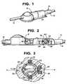
- FIG. 1is a perspective view of a shunt system incorporating a device for limiting the flow of a fluid from a first region of a patient's body to a second region in accordance with the present invention
- FIG. 2is a side view of the shunt system of FIG. 1 with parts broken away;
- FIG. 3is a cross-sectional view taken along lines 3 — 3 of FIG. 2 and looking in the direction of the arrows;
- FIG. 4is a cross-sectional view, similar to FIG. 3 , but showing the device in another position;
- FIG. 5is a cross-sectional view, similar to FIG. 3 , but showing the device without the magnetic bands and in another position;
- FIG. 6is a cross-sectional view of another embodiment of the device in accordance with the present invention, shown with the device in a supine position;
- FIG. 7is a cross-sectional view of the device of FIG. 6 shown in the upright position.
- FIG. 8is a cross-sectional view of the device of FIG. 6 , but showing the device without the magnetic bands and in another position.
- the systemincludes a housing 12 having an inlet 14 and an outlet 16 .
- a one-way valve 18is disposed within housing 12 .
- the spring bias of the one-way valveis preferably programmable, as is taught in U.S. Pat. Nos. 4,615,691 and 4,772,257 to Hakim et al. and U.S. Pat. No. 5,928,182 to Kraus et al., the disclosures of which are hereby incorporated by reference in their entirety.
- a subhousing 22is disposed within housing 20 , downstream from one-way valve 18 .
- Subhousing 22has a spherical inner surface 24 with a predetermined inner diameter.
- the subhousing 22has an inlet port 26 for receiving fluid from the first region and an outlet port 28 for directing fluid to the second region.
- the inlet port 26 and the outlet port 28are disposed approximately diametrically opposite from each other along essentially the same longitudinal axis A—A, as shown in FIG. 3 .
- a spherical ball 30is disposed within subhousing 22 .
- Spherical ball 30has a ferromagnetic weight 32 disposed off center therein.
- the remainder of spherical ballmay be made of a light-weight material, such as, for example, a biocompatible plastic. Plastic is preferred because it is light weight and has a smooth surface.
- spherical ball 30with the exception of weight 32 , may be hollow to create a maximum weight difference in ball 30 .
- Ball 30has a predetermined outer diameter that is less than the inner diameter of the subhousing 22 .
- the ratio of the inner diameter of the subhousing 22 to the outer diameter of the ballis preferably around 1.25:1.
- the cross-sectional area of the deviceis slightly smaller than the shunt so as to fit within the shunt housing, as illustrated in FIG. 2 .
- the spherical ball 30is free to rotate within subhousing 22 and the fluid is free to flow between the inner surface of the subhousing and an outer surface of the spherical ball.
- Spherical ball 30has a recess 34 extending about the circumference of the ball.
- a first magnetic band 36surrounds subhousing 22 .
- the first magnetic band 36has a plane of symmetry that is approximately normal to a line extending between the inlet port 26 and said outlet port 28 .
- a second magnetic band 38is disposed about outlet port 28 .
- the second magnetic band 38also has a plane of symmetry that is approximately normal to the line extending between the inlet port 26 and said outlet port 28 .
- the first magnetic band 36has one charge and the magnetic weight 32 has an opposite charge so that, in one position as illustrated in FIG. 2 , they are magnetically attracted toward one another.
- the second magnetic band 38has the same charge as the first magnetic band so that, in a second position illustrated in FIG. 3 , second magnetic band 38 and magnetic weight 32 are magnetically attracted toward one another.
- Subhousing 22is preferably made of a material that reduces electromagnetic interference.
- Subhousing 22is preferably made of metal, such as aluminum or titanium.
- subhousing 22In use, when the patient is in the supine position (e.g., lying down), subhousing 22 is placed essentially in a first position which causes the magnetic weight in the spherical ball to align with the first magnetic band such that the circumferential recess 34 within ball 30 is approximately co-linear with respect to the line between the inlet port 26 and the outlet port 28 . Thus, the maximum amount of fluid can flow through subhousing 22 .
- subhousing 22When the patient is in the upright position (e.g. standing or sitting up), subhousing 22 is placed essentially in a second position which causes the magnetic weight in the spherical ball to align with the second magnetic band 38 such that the circumferential recess 34 within ball 30 is normal with respect to the line between the inlet port 26 and the outlet port 28 .
- the first positionis disposed approximately ninety degrees from the second position.
- magnetic bands 36 , 38are not required, but is preferred to ensure that ball 30 will be aligned as illustrated in FIGS. 2 and 3 even when the patient is not disposed in a position that is exactly horizontal or vertical, respectively.
- the patient's headmay not be exactly horizontal, but may be inclined at an angle of, for example, 20 degrees.
- the magnetic attraction between the magnetic weight 32 within ball 30 and band 36will cause recess 34 to align with the inlet and outlet ports 26 , 28 .
- weight 32will always be drawn by the force of gravity to the lowest possible position within subhousing 22 .
- the recess 34will move gradually between the two extreme positions.
- the flow rate through the anti-siphon devicewill gradually reduce from the maximum flow rate (as shown if FIG. 2 ) to the minimum flow rate (as shown in FIG. 3 ).
- a subhousing 122is disposed within housing, downstream from the one-way valve.
- Subhousing 122has a spherical inner surface 124 with a predetermined inner diameter.
- the subhousing 122has an inlet port 126 for receiving fluid from the first region and an outlet port 128 for directing fluid to the second region.
- the inlet port 126 and the outlet port 128are disposed approximately diametrically opposite from each other along essentially the same longitudinal axis.
- a spherical ball 130is disposed within subhousing 122 .
- Spherical ball 130has a ferromagnetic weight 132 disposed off center therein. The remainder of spherical ball may be made of a light-weight material, such as, for example, a biocompatible plastic.
- Ball 130has a predetermined outer diameter that is less than the inner diameter of the subhousing 122 .
- Spherical ball 130has a recess 134 extending about the circumference of the ball.
- spherical ball 130has a through bore 140 extending through the ball 130 . Bore 140 is approximately normal to the plane defined by circumferential recess 134 .
- a first magnetic band 136surrounds subhousing 112 .
- the first magnetic band 136has a plane of symmetry that is approximately normal to a line extending between the inlet port 126 and said outlet port 128 .
- a second magnetic band 138is disposed about outlet port 128 .
- the second magnetic band 138also has a plane of symmetry that is approximately normal to the line extending between the inlet port 126 and said outlet port 128 .
- the first magnetic band 136has one charge and the magnetic weight 132 has an opposite charge so that, in one position as illustrated in FIG. 6 , they are magnetically attracted toward one another.
- the second magnetic band 138has the same charge as the first magnetic band so that, in a second position illustrated in FIG. 7 , second magnetic band 138 and magnetic weight 132 are magnetically attracted toward one another.
- subhousing 122In use, when the patient is in the supine position, subhousing 122 is placed essentially in a first position which causes the magnetic weight in the spherical ball to align with the first magnetic band such that the circumferential recess 134 within ball 130 is approximately co-linear with respect to the line between the inlet port 126 and the outlet port 128 . Thus, the maximum amount of fluid can flow through subhousing 122 .
- subhousing 122When the patient is in the upright position, subhousing 122 is placed essentially in a second position which causes the magnetic weight in the spherical ball to align with the second magnetic band 138 such that the circumferential recess 134 within ball 130 is normal with respect to the line between the inlet port 126 and the outlet port 128 .
- the first positionis disposed approximately ninety degrees from the second position.
- weight 132will always be drawn, by the force of gravity, to the lowest possible position within subhousing 122 .
- the recess 134will move gradually between the two extreme positions.
- the flow rate through the anti-siphon devicewill gradually reduce from the maximum flow rate (as shown if FIG. 6 ) to the minimum flow rate (as shown in FIG. 7 ).
Landscapes
- Health & Medical Sciences (AREA)
- Engineering & Computer Science (AREA)
- Biomedical Technology (AREA)
- Neurology (AREA)
- Ophthalmology & Optometry (AREA)
- Otolaryngology (AREA)
- Anesthesiology (AREA)
- Heart & Thoracic Surgery (AREA)
- Hematology (AREA)
- Life Sciences & Earth Sciences (AREA)
- Animal Behavior & Ethology (AREA)
- General Health & Medical Sciences (AREA)
- Public Health (AREA)
- Veterinary Medicine (AREA)
- External Artificial Organs (AREA)
Abstract
Description
Claims (30)
Priority Applications (1)
| Application Number | Priority Date | Filing Date | Title |
|---|---|---|---|
| US10/699,273US7118549B2 (en) | 2003-10-31 | 2003-10-31 | Shunt system including a flow control device for controlling the flow of cerebrospinal fluid out of a brain ventricle |
Applications Claiming Priority (1)
| Application Number | Priority Date | Filing Date | Title |
|---|---|---|---|
| US10/699,273US7118549B2 (en) | 2003-10-31 | 2003-10-31 | Shunt system including a flow control device for controlling the flow of cerebrospinal fluid out of a brain ventricle |
Publications (2)
| Publication Number | Publication Date |
|---|---|
| US20050096581A1 US20050096581A1 (en) | 2005-05-05 |
| US7118549B2true US7118549B2 (en) | 2006-10-10 |
Family
ID=34550909
Family Applications (1)
| Application Number | Title | Priority Date | Filing Date |
|---|---|---|---|
| US10/699,273Expired - LifetimeUS7118549B2 (en) | 2003-10-31 | 2003-10-31 | Shunt system including a flow control device for controlling the flow of cerebrospinal fluid out of a brain ventricle |
Country Status (1)
| Country | Link |
|---|---|
| US (1) | US7118549B2 (en) |
Cited By (35)
| Publication number | Priority date | Publication date | Assignee | Title |
|---|---|---|---|---|
| US20040122348A1 (en)* | 2002-12-24 | 2004-06-24 | Hokanson Charles P. | Gravitational pressure regulating mechanism |
| US20060247569A1 (en)* | 2005-04-29 | 2006-11-02 | Medtronic, Inc. | Implantable cerebral spinal fluid flow device and method of controlling flow of cerebral spinal fluid |
| US20100258560A1 (en)* | 2008-06-13 | 2010-10-14 | James Hilton Parnell | Anti Siphon Ball |
| US20100305492A1 (en)* | 2006-10-09 | 2010-12-02 | Shivanand Lad | Cerebrospinal Fluid Purification System |
| US20110112460A1 (en)* | 2009-11-09 | 2011-05-12 | Medtronic Xomed, Inc. | Adjustable valve setting with motor control |
| WO2011114260A1 (en) | 2010-03-19 | 2011-09-22 | Pfizer Inc. | Cerebrospinal fluid purification system |
| US20160003004A1 (en)* | 2013-02-25 | 2016-01-07 | Halliburton Energy Services, Inc. | Pressure equalization for dual seat ball valve |
| US9387311B1 (en) | 2014-10-31 | 2016-07-12 | Cerevasc, Llc | Methods and systems for treating hydrocephalus |
| US9435455B2 (en) | 2011-12-21 | 2016-09-06 | Deka Products Limited Partnership | System, method, and apparatus for monitoring, regulating, or controlling fluid flow |
| US9694166B2 (en) | 2002-03-26 | 2017-07-04 | Medtronics Ps Medical, Inc. | Method of draining cerebrospinal fluid |
| US9724466B2 (en) | 2011-12-21 | 2017-08-08 | Deka Products Limited Partnership | Flow meter |
| US9737696B2 (en) | 2014-01-15 | 2017-08-22 | Tufts Medical Center, Inc. | Endovascular cerebrospinal fluid shunt |
| US9737697B2 (en) | 2009-01-29 | 2017-08-22 | Tufts Medical Center, Inc. | Endovascular cerebrospinal fluid shunt |
| US9746093B2 (en) | 2011-12-21 | 2017-08-29 | Deka Products Limited Partnership | Flow meter and related system and apparatus |
| US9746094B2 (en) | 2011-12-21 | 2017-08-29 | Deka Products Limited Partnership | Flow meter having a background pattern with first and second portions |
| US9759343B2 (en) | 2012-12-21 | 2017-09-12 | Deka Products Limited Partnership | Flow meter using a dynamic background image |
| USD799025S1 (en) | 2013-11-06 | 2017-10-03 | Deka Products Limited Partnership | Apparatus to control fluid flow through a tube |
| USD802118S1 (en) | 2013-11-06 | 2017-11-07 | Deka Products Limited Partnership | Apparatus to control fluid flow through a tube |
| USD813376S1 (en) | 2013-11-06 | 2018-03-20 | Deka Products Limited Partnership | Apparatus to control fluid flow through a tube |
| USD815730S1 (en) | 2013-11-06 | 2018-04-17 | Deka Products Limited Partnership | Apparatus to control fluid flow through a tube |
| USD816829S1 (en) | 2013-11-06 | 2018-05-01 | Deka Products Limited Partnership | Apparatus to control fluid flow through a tube |
| US10088346B2 (en) | 2011-12-21 | 2018-10-02 | Deka Products Limited Partnership | System, method, and apparatus for monitoring, regulating, or controlling fluid flow |
| US10228683B2 (en) | 2011-12-21 | 2019-03-12 | Deka Products Limited Partnership | System, method, and apparatus for monitoring, regulating, or controlling fluid flow |
| USD854145S1 (en) | 2016-05-25 | 2019-07-16 | Deka Products Limited Partnership | Apparatus to control fluid flow through a tube |
| US10488848B2 (en) | 2011-12-21 | 2019-11-26 | Deka Products Limited Partnership | System, method, and apparatus for monitoring, regulating, or controlling fluid flow |
| US10632237B2 (en) | 2006-10-09 | 2020-04-28 | Minnetronix, Inc. | Tangential flow filter system for the filtration of materials from biologic fluids |
| US10850235B2 (en) | 2006-10-09 | 2020-12-01 | Minnetronix, Inc. | Method for filtering cerebrospinal fluid (CSF) including monitoring CSF flow |
| USD905848S1 (en) | 2016-01-28 | 2020-12-22 | Deka Products Limited Partnership | Apparatus to control fluid flow through a tube |
| US11147540B2 (en) | 2015-07-01 | 2021-10-19 | Minnetronix, Inc. | Introducer sheath and puncture tool for the introduction and placement of a catheter in tissue |
| US11278708B2 (en) | 2014-01-15 | 2022-03-22 | Tufts Medical Center, Inc. | Endovascular cerebrospinal fluid shunt |
| USD964563S1 (en) | 2019-07-26 | 2022-09-20 | Deka Products Limited Partnership | Medical flow clamp |
| US11577060B2 (en) | 2015-12-04 | 2023-02-14 | Minnetronix, Inc. | Systems and methods for the conditioning of cerebrospinal fluid |
| US11744935B2 (en) | 2016-01-28 | 2023-09-05 | Deka Products Limited Partnership | Apparatus for monitoring, regulating, or controlling fluid flow |
| US11839741B2 (en) | 2019-07-26 | 2023-12-12 | Deka Products Limited Partneship | Apparatus for monitoring, regulating, or controlling fluid flow |
| US12290785B2 (en) | 2015-08-05 | 2025-05-06 | Minnetronix, Inc. | Tangential flow filter system for the filtration of materials from biologic fluids |
Families Citing this family (3)
| Publication number | Priority date | Publication date | Assignee | Title |
|---|---|---|---|---|
| WO2007092875A2 (en)* | 2006-02-09 | 2007-08-16 | Pizzi Francis J | Dual channel shunt device and method for ventriculo-peritoneal shunting of bloody cerebrospinal fluid |
| DE102009060533B4 (en)* | 2009-12-23 | 2019-07-11 | Christoph Miethke Gmbh & Co Kg | Implantable shunt system |
| US9372486B2 (en) | 2011-12-21 | 2016-06-21 | Deka Products Limited Partnership | System, method, and apparatus for monitoring, regulating, or controlling fluid flow |
Citations (34)
| Publication number | Priority date | Publication date | Assignee | Title |
|---|---|---|---|---|
| US609062A (en) | 1898-08-16 | Chain adjustment for bicycles or other machines | ||
| US2753990A (en) | 1953-07-02 | 1956-07-10 | Chalfin Philip | Container |
| US3166083A (en)* | 1962-12-12 | 1965-01-19 | Barney B Girden | Breathing apparatus for swimmers |
| US3206160A (en)* | 1962-03-08 | 1965-09-14 | Donald C Bennett | Electromagnetic flow control system |
| US3373498A (en)* | 1965-06-11 | 1968-03-19 | Henri Jules Chabbert | Magnetic compass |
| US3883113A (en)* | 1974-03-29 | 1975-05-13 | Acf Ind Inc | Fluid control ball valve structure for throttling service |
| US3889687A (en) | 1974-01-31 | 1975-06-17 | Donald L Harris | Shunt system for the transport of cerebrospinal fluid |
| US3897809A (en) | 1974-06-21 | 1975-08-05 | Raymond Lee Organization Inc | Tiltable measuring trap with removable dispensing drawer |
| US4289165A (en)* | 1979-05-17 | 1981-09-15 | Otis Engineering Corporation | Equalizing ball valve member |
| US4298038A (en) | 1979-09-21 | 1981-11-03 | Jennings J Thomas | Technique and device for measuring fluids including finger valve and filler mechanism |
| US4443214A (en) | 1981-03-18 | 1984-04-17 | Society Dite: Sophysa | Valve for the treatment of hydrocephalus |
| US4552553A (en) | 1983-06-30 | 1985-11-12 | Pudenz-Schulte Medical Research Corp. | Flow control valve |
| US4560375A (en) | 1983-06-30 | 1985-12-24 | Pudenz-Schulte Medical Research Corp. | Flow control valve |
| US4610658A (en) | 1985-02-21 | 1986-09-09 | Henry Buchwald | Automated peritoneovenous shunt |
| US4615691A (en)* | 1983-12-08 | 1986-10-07 | Salomon Hakim | Surgically-implantable stepping motor |
| US4636194A (en) | 1983-06-30 | 1987-01-13 | Pudenz-Schulte Medical Research Corp. | Burr-hole flow control valve |
| US4651904A (en) | 1983-12-02 | 1987-03-24 | Bramlage Gesellschaft Mit Beschrankter Haftung | Dispenser for pasty compositions, particularly toothpaste dispenser |
| US4673384A (en) | 1986-04-14 | 1987-06-16 | Sophysa | Valve for the treatment of hydrocephalus |
| US4795437A (en) | 1987-01-29 | 1989-01-03 | Pudenz-Schulte Medical Research Corporation | Siphon control device |
| US5165576A (en) | 1991-10-16 | 1992-11-24 | Hickerson Frederick R | Dispenser for measured quantities of liquid |
| US5167615A (en) | 1990-05-15 | 1992-12-01 | Pudenz-Schulte Medical Research Corporation | Flow control device having selectable alternative fluid pathways |
| US5176627A (en) | 1990-05-15 | 1993-01-05 | Pudenz-Schulte Medical Research Corporation | Implantable fluid flow control device having two-piece base, and assembly process |
| US5185809A (en) | 1987-08-14 | 1993-02-09 | The General Hospital Corporation | Morphometric analysis of anatomical tomographic data |
| US5342025A (en)* | 1993-12-31 | 1994-08-30 | Hwang Shao Keh | Magnetic control-type flow control valve |
| US5556011A (en) | 1993-12-13 | 1996-09-17 | Jennings; Robert M. | Measuring container |
| US5643194A (en) | 1994-06-24 | 1997-07-01 | Sophysa | Subcutaneous valve and device for externally setting it |
| US5692945A (en) | 1996-09-18 | 1997-12-02 | Educational Design, Inc. | Toy producing simulated eruption |
| US5695093A (en) | 1995-09-12 | 1997-12-09 | T L Design Service Inc. | Controlled dose dispensing container having a dispensing receptacle for dispensing fluids |
| US5773414A (en) | 1991-05-16 | 1998-06-30 | Warner-Lambert Company | Endothelin antagonists |
| US5884816A (en) | 1997-08-01 | 1999-03-23 | Hinze; John F. | Liquid measuring device and method of using same |
| US5894856A (en)* | 1997-08-12 | 1999-04-20 | Swenson; Ralph R. | Seismically triggered valve |
| US6007814A (en) | 1992-06-15 | 1999-12-28 | Sloan-Kettering Institute For Cancer Research | Therapeutic uses of the hypervariable region of monoclonal antibody M195 and constructs thereof |
| US6126628A (en) | 1997-04-22 | 2000-10-03 | Johnson & Johnson Professional, Inc. | Fluid flow limiting device |
| US6383160B1 (en) | 1999-04-29 | 2002-05-07 | Children's Medical Center Corporation | Variable anti-siphon valve apparatus and method |
- 2003
- 2003-10-31USUS10/699,273patent/US7118549B2/ennot_activeExpired - Lifetime
Patent Citations (34)
| Publication number | Priority date | Publication date | Assignee | Title |
|---|---|---|---|---|
| US609062A (en) | 1898-08-16 | Chain adjustment for bicycles or other machines | ||
| US2753990A (en) | 1953-07-02 | 1956-07-10 | Chalfin Philip | Container |
| US3206160A (en)* | 1962-03-08 | 1965-09-14 | Donald C Bennett | Electromagnetic flow control system |
| US3166083A (en)* | 1962-12-12 | 1965-01-19 | Barney B Girden | Breathing apparatus for swimmers |
| US3373498A (en)* | 1965-06-11 | 1968-03-19 | Henri Jules Chabbert | Magnetic compass |
| US3889687A (en) | 1974-01-31 | 1975-06-17 | Donald L Harris | Shunt system for the transport of cerebrospinal fluid |
| US3883113A (en)* | 1974-03-29 | 1975-05-13 | Acf Ind Inc | Fluid control ball valve structure for throttling service |
| US3897809A (en) | 1974-06-21 | 1975-08-05 | Raymond Lee Organization Inc | Tiltable measuring trap with removable dispensing drawer |
| US4289165A (en)* | 1979-05-17 | 1981-09-15 | Otis Engineering Corporation | Equalizing ball valve member |
| US4298038A (en) | 1979-09-21 | 1981-11-03 | Jennings J Thomas | Technique and device for measuring fluids including finger valve and filler mechanism |
| US4443214A (en) | 1981-03-18 | 1984-04-17 | Society Dite: Sophysa | Valve for the treatment of hydrocephalus |
| US4636194A (en) | 1983-06-30 | 1987-01-13 | Pudenz-Schulte Medical Research Corp. | Burr-hole flow control valve |
| US4552553A (en) | 1983-06-30 | 1985-11-12 | Pudenz-Schulte Medical Research Corp. | Flow control valve |
| US4560375A (en) | 1983-06-30 | 1985-12-24 | Pudenz-Schulte Medical Research Corp. | Flow control valve |
| US4651904A (en) | 1983-12-02 | 1987-03-24 | Bramlage Gesellschaft Mit Beschrankter Haftung | Dispenser for pasty compositions, particularly toothpaste dispenser |
| US4615691A (en)* | 1983-12-08 | 1986-10-07 | Salomon Hakim | Surgically-implantable stepping motor |
| US4610658A (en) | 1985-02-21 | 1986-09-09 | Henry Buchwald | Automated peritoneovenous shunt |
| US4673384A (en) | 1986-04-14 | 1987-06-16 | Sophysa | Valve for the treatment of hydrocephalus |
| US4795437A (en) | 1987-01-29 | 1989-01-03 | Pudenz-Schulte Medical Research Corporation | Siphon control device |
| US5185809A (en) | 1987-08-14 | 1993-02-09 | The General Hospital Corporation | Morphometric analysis of anatomical tomographic data |
| US5167615A (en) | 1990-05-15 | 1992-12-01 | Pudenz-Schulte Medical Research Corporation | Flow control device having selectable alternative fluid pathways |
| US5176627A (en) | 1990-05-15 | 1993-01-05 | Pudenz-Schulte Medical Research Corporation | Implantable fluid flow control device having two-piece base, and assembly process |
| US5773414A (en) | 1991-05-16 | 1998-06-30 | Warner-Lambert Company | Endothelin antagonists |
| US5165576A (en) | 1991-10-16 | 1992-11-24 | Hickerson Frederick R | Dispenser for measured quantities of liquid |
| US6007814A (en) | 1992-06-15 | 1999-12-28 | Sloan-Kettering Institute For Cancer Research | Therapeutic uses of the hypervariable region of monoclonal antibody M195 and constructs thereof |
| US5556011A (en) | 1993-12-13 | 1996-09-17 | Jennings; Robert M. | Measuring container |
| US5342025A (en)* | 1993-12-31 | 1994-08-30 | Hwang Shao Keh | Magnetic control-type flow control valve |
| US5643194A (en) | 1994-06-24 | 1997-07-01 | Sophysa | Subcutaneous valve and device for externally setting it |
| US5695093A (en) | 1995-09-12 | 1997-12-09 | T L Design Service Inc. | Controlled dose dispensing container having a dispensing receptacle for dispensing fluids |
| US5692945A (en) | 1996-09-18 | 1997-12-02 | Educational Design, Inc. | Toy producing simulated eruption |
| US6126628A (en) | 1997-04-22 | 2000-10-03 | Johnson & Johnson Professional, Inc. | Fluid flow limiting device |
| US5884816A (en) | 1997-08-01 | 1999-03-23 | Hinze; John F. | Liquid measuring device and method of using same |
| US5894856A (en)* | 1997-08-12 | 1999-04-20 | Swenson; Ralph R. | Seismically triggered valve |
| US6383160B1 (en) | 1999-04-29 | 2002-05-07 | Children's Medical Center Corporation | Variable anti-siphon valve apparatus and method |
Cited By (73)
| Publication number | Priority date | Publication date | Assignee | Title |
|---|---|---|---|---|
| US9694166B2 (en) | 2002-03-26 | 2017-07-04 | Medtronics Ps Medical, Inc. | Method of draining cerebrospinal fluid |
| US7282040B2 (en)* | 2002-12-24 | 2007-10-16 | Vygon Us, Llc | Gravitational pressure regulating mechanism |
| US20040122348A1 (en)* | 2002-12-24 | 2004-06-24 | Hokanson Charles P. | Gravitational pressure regulating mechanism |
| US20060247569A1 (en)* | 2005-04-29 | 2006-11-02 | Medtronic, Inc. | Implantable cerebral spinal fluid flow device and method of controlling flow of cerebral spinal fluid |
| US10632237B2 (en) | 2006-10-09 | 2020-04-28 | Minnetronix, Inc. | Tangential flow filter system for the filtration of materials from biologic fluids |
| US10398884B2 (en) | 2006-10-09 | 2019-09-03 | Neurofluidics, Inc. | Cerebrospinal fluid purification system |
| US20200046954A1 (en) | 2006-10-09 | 2020-02-13 | Neurofluidics, Inc. | Cerebrospinal fluid purification system |
| US9895518B2 (en) | 2006-10-09 | 2018-02-20 | Neurofluidics, Inc. | Cerebrospinal fluid purification system |
| US8435204B2 (en) | 2006-10-09 | 2013-05-07 | Neurofluidics, Inc. | Cerebrospinal fluid purification system |
| US20100305492A1 (en)* | 2006-10-09 | 2010-12-02 | Shivanand Lad | Cerebrospinal Fluid Purification System |
| US12280229B2 (en) | 2006-10-09 | 2025-04-22 | Neurofluidics, Inc. | Cerebrospinal fluid purification system |
| US11529452B2 (en) | 2006-10-09 | 2022-12-20 | Minnetronix, Inc. | Tangential flow filter system for the filtration of materials from biologic fluids |
| US11065425B2 (en) | 2006-10-09 | 2021-07-20 | Neurofluidics, Inc. | Cerebrospinal fluid purification system |
| US10850235B2 (en) | 2006-10-09 | 2020-12-01 | Minnetronix, Inc. | Method for filtering cerebrospinal fluid (CSF) including monitoring CSF flow |
| US20100258560A1 (en)* | 2008-06-13 | 2010-10-14 | James Hilton Parnell | Anti Siphon Ball |
| US9737697B2 (en) | 2009-01-29 | 2017-08-22 | Tufts Medical Center, Inc. | Endovascular cerebrospinal fluid shunt |
| US10112036B2 (en) | 2009-01-29 | 2018-10-30 | Tufts Medical Center, Inc. | Endovascular cerebrospinal fluid shunt |
| US8753331B2 (en) | 2009-11-09 | 2014-06-17 | Medtronic Xomed, Inc. | Adjustable valve setting with motor control |
| US8241240B2 (en)* | 2009-11-09 | 2012-08-14 | Medtronic Xomed, Inc. | Adjustable valve setting with motor control |
| US20110112460A1 (en)* | 2009-11-09 | 2011-05-12 | Medtronic Xomed, Inc. | Adjustable valve setting with motor control |
| WO2011114260A1 (en) | 2010-03-19 | 2011-09-22 | Pfizer Inc. | Cerebrospinal fluid purification system |
| US10228683B2 (en) | 2011-12-21 | 2019-03-12 | Deka Products Limited Partnership | System, method, and apparatus for monitoring, regulating, or controlling fluid flow |
| US10844970B2 (en) | 2011-12-21 | 2020-11-24 | Deka Products Limited Partnership | Flow meter |
| US9772044B2 (en) | 2011-12-21 | 2017-09-26 | Deka Products Limited Partnership | Flow metering using a difference image for liquid parameter estimation |
| US12100507B2 (en) | 2011-12-21 | 2024-09-24 | Deka Products Limited Partnership | System, method, and apparatus for monitoring, regulating, or controlling fluid flow |
| US11793928B2 (en) | 2011-12-21 | 2023-10-24 | Deka Products Limited Partnership | Flow meter and related method |
| US9856990B2 (en) | 2011-12-21 | 2018-01-02 | Deka Products Limited Partnership | Flow metering using a difference image for liquid parameter estimation |
| US9746094B2 (en) | 2011-12-21 | 2017-08-29 | Deka Products Limited Partnership | Flow meter having a background pattern with first and second portions |
| US11738143B2 (en) | 2011-12-21 | 2023-08-29 | Deka Products Limited Partnership | Flow meier having a valve |
| US11574407B2 (en) | 2011-12-21 | 2023-02-07 | Deka Products Limited Partnership | System, method, and apparatus for monitoring, regulating, or controlling fluid flow |
| US11449037B2 (en) | 2011-12-21 | 2022-09-20 | Deka Products Limited Partnership | System, method, and apparatus for monitoring, regulating, or controlling fluid flow |
| US9976665B2 (en) | 2011-12-21 | 2018-05-22 | Deka Products Limited Partnership | Flow meter |
| US10088346B2 (en) | 2011-12-21 | 2018-10-02 | Deka Products Limited Partnership | System, method, and apparatus for monitoring, regulating, or controlling fluid flow |
| US10113660B2 (en) | 2011-12-21 | 2018-10-30 | Deka Products Limited Partnership | Flow meter |
| US9746093B2 (en) | 2011-12-21 | 2017-08-29 | Deka Products Limited Partnership | Flow meter and related system and apparatus |
| US11339887B2 (en) | 2011-12-21 | 2022-05-24 | Deka Products Limited Partnership | Flow meter and related method |
| US9435455B2 (en) | 2011-12-21 | 2016-09-06 | Deka Products Limited Partnership | System, method, and apparatus for monitoring, regulating, or controlling fluid flow |
| US9724467B2 (en) | 2011-12-21 | 2017-08-08 | Deka Products Limited Partnership | Flow meter |
| US10894638B2 (en) | 2011-12-21 | 2021-01-19 | Deka Products Limited Partnership | System, method, and apparatus for monitoring, regulating, or controlling fluid flow |
| US10436342B2 (en) | 2011-12-21 | 2019-10-08 | Deka Products Limited Partnership | Flow meter and related method |
| US10488848B2 (en) | 2011-12-21 | 2019-11-26 | Deka Products Limited Partnership | System, method, and apparatus for monitoring, regulating, or controlling fluid flow |
| US9724465B2 (en) | 2011-12-21 | 2017-08-08 | Deka Products Limited Partnership | Flow meter |
| US10876868B2 (en) | 2011-12-21 | 2020-12-29 | Deka Products Limited Partnership | System, method, and apparatus for monitoring, regulating, or controlling fluid flow |
| US9724466B2 (en) | 2011-12-21 | 2017-08-08 | Deka Products Limited Partnership | Flow meter |
| US10718445B2 (en) | 2011-12-21 | 2020-07-21 | Deka Products Limited Partnership | Flow meter having a valve |
| US10739759B2 (en) | 2011-12-21 | 2020-08-11 | Deka Products Limited Partnership | System, method, and apparatus for monitoring, regulating, or controlling fluid flow |
| US9759343B2 (en) | 2012-12-21 | 2017-09-12 | Deka Products Limited Partnership | Flow meter using a dynamic background image |
| US9657550B2 (en)* | 2013-02-25 | 2017-05-23 | Halliburton Energy Services, Inc. | Pressure equalization for dual seat ball valve |
| US20160003004A1 (en)* | 2013-02-25 | 2016-01-07 | Halliburton Energy Services, Inc. | Pressure equalization for dual seat ball valve |
| USD813376S1 (en) | 2013-11-06 | 2018-03-20 | Deka Products Limited Partnership | Apparatus to control fluid flow through a tube |
| USD815730S1 (en) | 2013-11-06 | 2018-04-17 | Deka Products Limited Partnership | Apparatus to control fluid flow through a tube |
| USD802118S1 (en) | 2013-11-06 | 2017-11-07 | Deka Products Limited Partnership | Apparatus to control fluid flow through a tube |
| USD816829S1 (en) | 2013-11-06 | 2018-05-01 | Deka Products Limited Partnership | Apparatus to control fluid flow through a tube |
| USD799025S1 (en) | 2013-11-06 | 2017-10-03 | Deka Products Limited Partnership | Apparatus to control fluid flow through a tube |
| US11278708B2 (en) | 2014-01-15 | 2022-03-22 | Tufts Medical Center, Inc. | Endovascular cerebrospinal fluid shunt |
| US9737696B2 (en) | 2014-01-15 | 2017-08-22 | Tufts Medical Center, Inc. | Endovascular cerebrospinal fluid shunt |
| US12090291B2 (en) | 2014-01-15 | 2024-09-17 | Tufts Medical Center, Inc. | Endovascular cerebrospinal fluid shunt |
| US10596357B2 (en) | 2014-01-15 | 2020-03-24 | Tufts Medical Center, Inc. | Endovascular cerebrospinal fluid shunt |
| US9387311B1 (en) | 2014-10-31 | 2016-07-12 | Cerevasc, Llc | Methods and systems for treating hydrocephalus |
| US11147540B2 (en) | 2015-07-01 | 2021-10-19 | Minnetronix, Inc. | Introducer sheath and puncture tool for the introduction and placement of a catheter in tissue |
| US12290785B2 (en) | 2015-08-05 | 2025-05-06 | Minnetronix, Inc. | Tangential flow filter system for the filtration of materials from biologic fluids |
| US12364952B2 (en) | 2015-08-05 | 2025-07-22 | Minnetronix, Inc. | Tangential flow filter system for the filtration of materials from biologic fluids |
| US11577060B2 (en) | 2015-12-04 | 2023-02-14 | Minnetronix, Inc. | Systems and methods for the conditioning of cerebrospinal fluid |
| US11744935B2 (en) | 2016-01-28 | 2023-09-05 | Deka Products Limited Partnership | Apparatus for monitoring, regulating, or controlling fluid flow |
| USD943736S1 (en) | 2016-01-28 | 2022-02-15 | Deka Products Limited Partnership | Apparatus to control fluid flow through a tube |
| USD905848S1 (en) | 2016-01-28 | 2020-12-22 | Deka Products Limited Partnership | Apparatus to control fluid flow through a tube |
| USD972718S1 (en) | 2016-05-25 | 2022-12-13 | Deka Products Limited Partnership | Apparatus to control fluid flow through a tube |
| USD972125S1 (en) | 2016-05-25 | 2022-12-06 | Deka Products Limited Partnership | Apparatus to control fluid flow through a tube |
| USD1060608S1 (en) | 2016-05-25 | 2025-02-04 | Deka Products Limited Partnership | Device to control fluid flow through a tube |
| USD854145S1 (en) | 2016-05-25 | 2019-07-16 | Deka Products Limited Partnership | Apparatus to control fluid flow through a tube |
| USD860437S1 (en) | 2016-05-25 | 2019-09-17 | Deka Products Limited Partnership | Apparatus to control fluid flow through a tube |
| US11839741B2 (en) | 2019-07-26 | 2023-12-12 | Deka Products Limited Partneship | Apparatus for monitoring, regulating, or controlling fluid flow |
| USD964563S1 (en) | 2019-07-26 | 2022-09-20 | Deka Products Limited Partnership | Medical flow clamp |
Also Published As
| Publication number | Publication date |
|---|---|
| US20050096581A1 (en) | 2005-05-05 |
Similar Documents
| Publication | Publication Date | Title |
|---|---|---|
| US7118549B2 (en) | Shunt system including a flow control device for controlling the flow of cerebrospinal fluid out of a brain ventricle | |
| US6090062A (en) | Programmable antisiphon shunt system | |
| JP4028080B2 (en) | Fluid flow restriction device | |
| US8088092B2 (en) | High pressure range hydrocephalus valve system | |
| US6953444B2 (en) | Inherent anti-siphon device | |
| JP3532219B2 (en) | Hydrocephalus treatment device | |
| US7922685B2 (en) | Self adjusting hydrocephalus valve | |
| JP6381933B2 (en) | Two-phase fluid surge suppressor | |
| EP1386634B1 (en) | Cerebrospinal fluid shunt system incorporating an adjustable resistance valve | |
| JP7000453B2 (en) | Flow regulator | |
| US20040082900A1 (en) | Proportional control device for a hydrocephalus shunt | |
| US7282040B2 (en) | Gravitational pressure regulating mechanism | |
| US9731102B2 (en) | Adjustable resistance, gravitationally activated, anti-siphon valve | |
| US5810761A (en) | Intraventricular pressure control device | |
| CA2610650A1 (en) | Fluid flow limited device |
Legal Events
| Date | Code | Title | Description |
|---|---|---|---|
| AS | Assignment | Owner name:CODMAN & SHURTLEFF, INC., MASSACHUSETTS Free format text:ASSIGNMENT OF ASSIGNORS INTEREST;ASSIGNOR:CHAN, IAN;REEL/FRAME:014663/0853 Effective date:20031030 | |
| STCF | Information on status: patent grant | Free format text:PATENTED CASE | |
| FPAY | Fee payment | Year of fee payment:4 | |
| FPAY | Fee payment | Year of fee payment:8 | |
| AS | Assignment | Owner name:DEPUY SPINE, LLC, MASSACHUSETTS Free format text:ASSIGNMENT OF ASSIGNORS INTEREST;ASSIGNOR:CODMAN & SHURTLEFF, INC.;REEL/FRAME:045058/0627 Effective date:20121230 | |
| AS | Assignment | Owner name:HAND INNOVATIONS LLC, FLORIDA Free format text:ASSIGNMENT OF ASSIGNORS INTEREST;ASSIGNOR:DEPUY SPINE, LLC;REEL/FRAME:045074/0943 Effective date:20121230 Owner name:DEPUY SYNTHES PRODUCTS, LLC, MASSACHUSETTS Free format text:CHANGE OF NAME;ASSIGNOR:HAND INNOVATIONS LLC;REEL/FRAME:045476/0712 Effective date:20121231 Owner name:DEPUY SYNTHES PRODUCTS, INC., INDIANA Free format text:CHANGE OF NAME;ASSIGNOR:DEPUY SYNTHES PRODUCTS, LLC;REEL/FRAME:045479/0763 Effective date:20141219 | |
| AS | Assignment | Owner name:INTEGRA LIFESCIENCES SWITZERLAND SARL, SWITZERLAND Free format text:ASSIGNMENT OF ASSIGNORS INTEREST;ASSIGNOR:DEPUY SYNTHES PRODUCTS, INC.;REEL/FRAME:045569/0299 Effective date:20171002 | |
| MAFP | Maintenance fee payment | Free format text:PAYMENT OF MAINTENANCE FEE, 12TH YEAR, LARGE ENTITY (ORIGINAL EVENT CODE: M1553) Year of fee payment:12 |