US7118303B2 - Internally disposed linear fastener system - Google Patents
Internally disposed linear fastener systemDownload PDFInfo
- Publication number
- US7118303B2 US7118303B2US10/733,160US73316003AUS7118303B2US 7118303 B2US7118303 B2US 7118303B2US 73316003 AUS73316003 AUS 73316003AUS 7118303 B2US7118303 B2US 7118303B2
- Authority
- US
- United States
- Prior art keywords
- body member
- expander
- engaging
- cavity
- expandable portion
- Prior art date
- Legal status (The legal status is an assumption and is not a legal conclusion. Google has not performed a legal analysis and makes no representation as to the accuracy of the status listed.)
- Expired - Lifetime
Links
Images


Classifications
- F—MECHANICAL ENGINEERING; LIGHTING; HEATING; WEAPONS; BLASTING
- F16—ENGINEERING ELEMENTS AND UNITS; GENERAL MEASURES FOR PRODUCING AND MAINTAINING EFFECTIVE FUNCTIONING OF MACHINES OR INSTALLATIONS; THERMAL INSULATION IN GENERAL
- F16B—DEVICES FOR FASTENING OR SECURING CONSTRUCTIONAL ELEMENTS OR MACHINE PARTS TOGETHER, e.g. NAILS, BOLTS, CIRCLIPS, CLAMPS, CLIPS OR WEDGES; JOINTS OR JOINTING
- F16B33/00—Features common to bolt and nut
- F16B33/006—Non-metallic fasteners using screw-thread
- F—MECHANICAL ENGINEERING; LIGHTING; HEATING; WEAPONS; BLASTING
- F16—ENGINEERING ELEMENTS AND UNITS; GENERAL MEASURES FOR PRODUCING AND MAINTAINING EFFECTIVE FUNCTIONING OF MACHINES OR INSTALLATIONS; THERMAL INSULATION IN GENERAL
- F16B—DEVICES FOR FASTENING OR SECURING CONSTRUCTIONAL ELEMENTS OR MACHINE PARTS TOGETHER, e.g. NAILS, BOLTS, CIRCLIPS, CLAMPS, CLIPS OR WEDGES; JOINTS OR JOINTING
- F16B35/00—Screw-bolts; Stay-bolts; Screw-threaded studs; Screws; Set screws
- F16B35/005—Set screws; Locking means therefor
- F—MECHANICAL ENGINEERING; LIGHTING; HEATING; WEAPONS; BLASTING
- F16—ENGINEERING ELEMENTS AND UNITS; GENERAL MEASURES FOR PRODUCING AND MAINTAINING EFFECTIVE FUNCTIONING OF MACHINES OR INSTALLATIONS; THERMAL INSULATION IN GENERAL
- F16B—DEVICES FOR FASTENING OR SECURING CONSTRUCTIONAL ELEMENTS OR MACHINE PARTS TOGETHER, e.g. NAILS, BOLTS, CIRCLIPS, CLAMPS, CLIPS OR WEDGES; JOINTS OR JOINTING
- F16B39/00—Locking of screws, bolts or nuts
- F16B39/02—Locking of screws, bolts or nuts in which the locking takes place after screwing down
- F16B39/023—Locking of screws, bolts or nuts in which the locking takes place after screwing down by driving a conic or wedge-shaped expander through the threaded element
- F—MECHANICAL ENGINEERING; LIGHTING; HEATING; WEAPONS; BLASTING
- F16—ENGINEERING ELEMENTS AND UNITS; GENERAL MEASURES FOR PRODUCING AND MAINTAINING EFFECTIVE FUNCTIONING OF MACHINES OR INSTALLATIONS; THERMAL INSULATION IN GENERAL
- F16B—DEVICES FOR FASTENING OR SECURING CONSTRUCTIONAL ELEMENTS OR MACHINE PARTS TOGETHER, e.g. NAILS, BOLTS, CIRCLIPS, CLAMPS, CLIPS OR WEDGES; JOINTS OR JOINTING
- F16B2200/00—Constructional details of connections not covered for in other groups of this subclass
- F16B2200/69—Redundant disconnection blocking means
- F16B2200/71—Blocking disengagement of catches or keys
- Y—GENERAL TAGGING OF NEW TECHNOLOGICAL DEVELOPMENTS; GENERAL TAGGING OF CROSS-SECTIONAL TECHNOLOGIES SPANNING OVER SEVERAL SECTIONS OF THE IPC; TECHNICAL SUBJECTS COVERED BY FORMER USPC CROSS-REFERENCE ART COLLECTIONS [XRACs] AND DIGESTS
- Y10—TECHNICAL SUBJECTS COVERED BY FORMER USPC
- Y10S—TECHNICAL SUBJECTS COVERED BY FORMER USPC CROSS-REFERENCE ART COLLECTIONS [XRACs] AND DIGESTS
- Y10S411/00—Expanded, threaded, driven, headed, tool-deformed, or locked-threaded fastener
- Y10S411/924—Coupled nut and bolt
- Y10S411/954—Wedged slotted bolt
- Y—GENERAL TAGGING OF NEW TECHNOLOGICAL DEVELOPMENTS; GENERAL TAGGING OF CROSS-SECTIONAL TECHNOLOGIES SPANNING OVER SEVERAL SECTIONS OF THE IPC; TECHNICAL SUBJECTS COVERED BY FORMER USPC CROSS-REFERENCE ART COLLECTIONS [XRACs] AND DIGESTS
- Y10—TECHNICAL SUBJECTS COVERED BY FORMER USPC
- Y10T—TECHNICAL SUBJECTS COVERED BY FORMER US CLASSIFICATION
- Y10T403/00—Joints and connections
- Y10T403/70—Interfitted members
- Y10T403/7041—Interfitted members including set screw
- Y—GENERAL TAGGING OF NEW TECHNOLOGICAL DEVELOPMENTS; GENERAL TAGGING OF CROSS-SECTIONAL TECHNOLOGIES SPANNING OVER SEVERAL SECTIONS OF THE IPC; TECHNICAL SUBJECTS COVERED BY FORMER USPC CROSS-REFERENCE ART COLLECTIONS [XRACs] AND DIGESTS
- Y10—TECHNICAL SUBJECTS COVERED BY FORMER USPC
- Y10T—TECHNICAL SUBJECTS COVERED BY FORMER US CLASSIFICATION
- Y10T403/00—Joints and connections
- Y10T403/70—Interfitted members
- Y10T403/7062—Clamped members
Definitions
- the present inventionrelates to an internally disposed linear fastener system. More specifically, to a linear engaging set screw system utilizing an outwardly expandable set screw in combination with an internal linear traversable sleeve member.
- the inner sleeve memberis capable of rapid linear traversing engagement and disengagement to form a versatile and effective vibration resistant fastener system which may be used to reproducibly interconnect disparate components.
- a fasteneris any device used to connect or join two or more components to create an assembly.
- assembly processesrequiring individual components to be joined with fasteners to create an assembled product.
- fixations of one component in relation to anotherare currently performed using threaded fasteners for connections.
- the most common threaded fastenersare referred to by many names, among them: bolts, screws, nuts, studs, lag screws, and set screws.
- a clamping loadis produced by exerting a rotational torque on a threaded fastener that is converted to linear travel via the helical threads. These forces keep the threads of the mating parts in intimate contact and decrease the probability of the fastener loosening in service.
- threaded fasteners loosen over time when the part to which the fastener is affixedis subjected to shock or vibration. This is particularly true of threaded type fasteners used on devices with moving parts or in conjunction with motors or vehicles.
- locking fastenerslock washers, plastic inserts in the nut or bolt, adhesives, cotter pins, locking tabs, etc., are available to hold a threaded fastener in place until it is purposefully loosened. Most of these locking devices cooperate in one way or another with the head of the fastener.
- a typical bolt with a headcannot be used; for example, in situations where a head would limit the distance the bolt could be tightened into an aperture or where a protruding head on a moving or rotating part could damage equipment or personnel.
- a set screwis typically used in place of a bolt. Devices such as lock washers cannot be used to hold headless fasteners in place and thus they are especially prone to loosening.
- a typical application for set screwsis securing collars to shafts. In these applications, a set screw is tightened within a threaded aperture in a collar to apply pressure to the side of the shaft. Because the set screws are subjected to shock each time the shaft is started and vibration while the shaft is rotating, the set screws often loosen over time increasing the required machinery maintenance.
- the set screw locking systemshould achieve objectives such as providing improved manufacturing and assembly efficiency, effective reliable performance, corrosion resistance, and torqueless locking assembly.
- the systemshould include packaging flexibility for installation on various products, including retrofitting existing product configurations with minimal modification of the original product.
- U.S. Pat. No. 2,900,863teaches a two piece expansion bolt with a cylindrical shank and an expansion plug. When the shank of this fastener is driven into an aperture, the expansion plug acts to expand and wedge the lower end of the fastener against the walls of the aperture. The wedged lower end of the bolt prevents the bolt from turning when a cooperating nut is threaded onto the upper end of the bolt.
- fastenerscapable of partial linear and partial rotational engagement.
- These fastenersgenerally feature radially inwardly or outwardly biased arcuate segments mounted to engage the threads of a bolt, nut or other threaded member.
- the threaded segmentsare generally movably mounted within a casing or around a shaft and resiliently urged inwardly or outwardly.
- the devicesare provided with axially spaced apart radially inwardly directed surfaces of revolution, such as frustoconical surfaces, extending at a common acute angle to the axis of the fastener. In this manner the fasteners and couplings may be secured by merely pushing the threaded components together, thereafter final tightening is accomplished by rotation of the fasteners.
- U.S. Pat. No. 5,788,443teaches a male coupling device featuring movably mounted threaded members which are capable of rapid engagement and disengagement with respect to the stationary threads of a female coupling device.
- the male coupling deviceincludes a handled shaft having a plurality of threaded segments surrounding the shaft.
- a sleeveis mounted to move relative to the handle to move the threaded segments inwardly and outwardly to effectively vary the diameter of the assembled threaded elements.
- U.S. Pat. No. 5,244,323teaches a threaded, locking set screw having a threaded body, a resilient expansion plug, and a retaining wedge.
- the threaded bodyhas a tapered cavity at its bottom end.
- the expansion plug and retaining wedgeare aligned and inserted into the cavity in the bottom portion of the body.
- the base of the plugextends outwardly from the cavity, and the plug is held in place by a force fit between the wedge and a retaining slot in the body.
- the plugis forced into the cavity. Because of a locking taper between the plug and the cavity, the plug exerts an outward force on the inner surface of the cavity causing the set screw body to expand radially, thus, locking the set screw in place.
- the present inventionteaches a linear locking set screw system that includes a standard diameter threaded set screw and an inner compressing ring member that is capable of rapid linear actuated locking engagement and/or disengagement.
- the present inventionteaches a linear locking set screw that is capable of applying precise secondary clamping force to disparate assembled components without requiring rotation of the fastening members.
- the present inventionprovides a linear locking set screw system capable of rapid linear engagement and disengagement. More specifically, the system utilizes a threaded outwardly expandable set screw and an expander member which are constructed and arranged to thread easily into a threaded aperture while in a first release position and can thereafter be securely locked in place and/or provide a secondary clamping force in a second engaged position.
- the set screw memberis constructed and arranged with a standard sized outer threaded surface and an inner cavity including a driving and a frustaconical surface, the expander member being constructed and arranged with an inner threaded surface and an outer frustaconical surface preferably conjugate in shape with respect to the inner frustaconical surface of the set screw member.
- the set screw bodyis threaded into a threaded aperture and tightened to a desired torque.
- the set screw bodyis locked in place by traversing the expander member in a linear fashion along the axis of rotation of the set screw, so as to insert said expander member within the inner cavity in the upper portion of the set screw body, thereby utilizing the frustaconical surfaces to expand the set screw body and place a compressive load on the expander member to expand the set screw body to grip the inner threaded aperture surface.
- the set screw body memberis constructed and arranged with an undersized diameter threaded surface and an inner cavity including a driving and a frustaconical surface, the expander member being constructed and arranged with an inner threaded surface and an outer frustaconical surface preferably conjugate in shape with respect to the inner frustaconical surface of the set screw body member.
- the set screw bodyis threaded into a threaded aperture until the distal end of the set screw contacts the desired surface.
- the expander memberis inserted in a linear fashion into the cavity in the upper portion of the set screw body, thereby utilizing the frustaconical surfaces to expand the set screw body and place a compressive load on the expander member to expand the set screw outwardly.
- the threaded surfacescooperate in a helical or circular ramping fashion to force the set screw downward, thereby causing a secondary clamping load between the components.
- the locking set screw systemis capable of providing a precise, secure, and reproducible connection between multiple components.
- the connectionalso allows full thread engagement and a locking connection without the need for plastic inserts or adhesives.
- the dual frustaconical compression surfacesallow very precise clamping loads to be applied to the assembled components with or without application of rotational torque.
- Prior art designsrequire torque wrenches to apply measured clamping loads to fasteners. Linear expansion of the set screw member eliminates torque variations as seen in the prior art due to surface finish, lubrication and thread engagement to achieve a precise clamping load.
- An additional objective of the present inventionis to provide a fastener system capable of precise and reproducible linear engagement and disengagement.
- a still further objective of the present inventionis to provide a fastener system capable of providing precise and reproducible linear engagement to internal circular ramps and the like.
- Yet another objective of the present inventionis to provide a fastener system suited for automated manufacturing and assembly.
- Still yet another objective of the present inventionis to provide a fastener system that enables close spacing of the assembled components and does not require wrench clearances.
- Yet a further objective of the instant inventionis to teach the use of linear fasteners for modular implants having an element anchored in bone and a support element for ancillary devices, each with a cooperating coupling component adapted to be secured together without rotational torque forces.
- An additional objective of the instant inventionto teach a linear coupling device for medical implants with a pressure limiting element.
- FIG. 1shows a perspective view of one embodiment of the instant invention being utilized to secure a shaft within a component
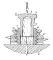
- FIG. 2shows a section view along line 1 — 1 of the embodiment illustrated in FIG. 1 , illustrating the set screw body member with the expander member in the engaged position;
- FIG. 3shows a perspective view of one embodiment of the set screw body member of this invention
- FIG. 4shows a perspective view of one embodiment of the expander member of this invention
- FIG. 5shows a perspective view of one embodiment of the instant invention being utilized to secure an alignment rod within a lateral support of a pedicle screw
- FIG. 6shows a section view along lines 2 — 2 of the embodiment illustrated in FIG. 5 , illustrating the set screw body member with the expander member in the engaged position;
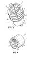
- FIG. 7shows a perspective view of one embodiment of the set screw body member of this invention.
- FIG. 8shows a perspective view of one embodiment of the expander member of this invention.
- FIG. 9shows a partial cross sectional view of one embodiment of this invention, illustrating the relative motions that result in the secondary clamping force during assembly of the instant invention
- FIG. 10schematically shows an alternative embodiment of the invention, wherein the clamping surface and the radially projecting means on the outer surface of the set screw include knurled surfaces.
- the linear engaging headless set screw 10 utilized to secure the shaft 14 within a machinery component 15is a representation of the general utility of the present invention.
- the linear engaging headless set screw 10 of the instant inventiongenerally comprises an axially aligned body member 11 and expander member 12 .
- the body member 11comprises a generally cylindrical outer surface 16 having a first end 18 and a second end 20 .
- the body member 11may be constructed of materials well known in the art which may include but should not be limited to steel, bronze, brass, copper, aluminum, plastic, ceramic, or rubber, as well as suitable combinations thereof.
- the first end 18 of the body member 11includes a cavity 22 and a driving means.
- the cavity 22includes an engaging surface 26 , the engaging surface tapering inwardly beginning at the first end and extending toward the second end of the body member 11 .
- the engaging surfaceincludes a self-holding taper such as a MORSE, BROWN & SHARPE (JARNO), AMERICAN NATIONAL STANDARD MACHINE TAPER (JACOBS), BRITISH STANDARD TAPERS and the like all well known in the art.
- a self-holding tapersuch as a MORSE, BROWN & SHARPE (JARNO), AMERICAN NATIONAL STANDARD MACHINE TAPER (JACOBS), BRITISH STANDARD TAPERS and the like all well known in the art.
- self-releasing taperswill known in the art suitable for circumferential expansion of the upper portion 28 of the body member 11 may be used.
- the driving meanscomprises at least one and preferably a plurality of driving surfaces 24 .
- the driving surfaces 24are constructed and arranged to cooperate with a standard hex wrench (not shown).
- the second end 20 of the set screw bodyis constructed and arranged as a clamping surface 30 ( FIG. 2 ).
- the clamping surface 30 in the preferred embodimentis a flat point.
- other set screw pointssuch as a dog point, half dog point, cup point, oval point, cone point or knurled point, all well known in the art, may be utilized with the instant invention.
- the body member 11preferably includes a radially projecting means for engaging the inner surface of an aperture illustrated herein as outwardly and circumferentially extending rib(s) 32 ( FIG.
- each circumferentially extending rib 32being constructed with a first ramp surface 36 to allow the set screw member to slide into the aperture and a second ramp surface 38 to allow a second clamping force as the engagement of expander 12 causes radial expansion of the set screw body 11 .
- the outer gripping surfacemay also include any number of surface finishes well known in the art to enhance the gripping action between the set screw body and cooperating aperture, including but not limited to, threads, knurling, snap ring grooves, generally smooth and/or tapers, or suitable combinations thereof, as well as other surfaces suitable for providing adequate grip between the set screw body 11 and the inner surface of an aperture 40 to secure an assembly.
- the upper portion 28 of the body 11includes at least one generally vertical slot 48 extending from the upper portion 28 of the set screw body 11 toward the second end 30 .
- the vertical slot(s) 48facilitates translation of the radial and outward forces created upon insertion of the expander member within the upper portion 28 of the body member 1 into a relatively uniform circumferential expansion of said body member 11 .
- Knurled clamping surface 30 and outer gripping surface 1010are schematically shown in FIG. 10 .
- the expander member 12comprises a body 46 having a first end 42 and a second end 44 .
- the outer surface 48in the preferred embodiment having a frustaconical taper generally conjugate to the taper within the set screw body cavity 22 .
- the outer surface taper 48is a self-holding taper such as a MORSE, BROWN & SHARPE (JARNO), AMERICAN NATIONAL STANDARD MACHINE TAPER (JACOBS), BRITISH STANDARD TAPERS or the like all well known in the art.
- other tapers well known in the art suitable for circumferential expansion of the upper portion 28 of the set screw body 11may be used.
- the expander member 12may include an inner bore 50 extending inwardly from said first end of said expander member along a longitudinal centerline for gripping the expander member 12 for extraction from the set screw body 11 .
- the inner surfacemay also include a driving means such as, but not limited to threads, sockets or slots for engagement with wrenches, screwdrivers and/or an extractor (not shown) used to remove or disconnect the coupling.
- the expander member 12may include a flange 52 ( FIGS. 6 and 8 ) at its second end 44 , the flange 52 having a larger diameter than the second end 44 of the expander member 12 to remove or disconnect the coupling.
- connection means(not shown) which allow the set screw member and the expander member to be interlocked into a coaxially aligned sub-assembly prior to insertion into an aperture.
- Suitable connection meansinclude adhesives, living hinges and the like.
- the linear engaging headless set screw 10is illustrated securing an alignment rod 60 within a lateral support 62 of a pedicle screw assembly 64 illustrating the particularly low profile constructions possible with the instant invention.
- the assembly of one embodiment of the instant invention and relative motion in relation theretois illustrated.
- the set screw body 11is loosely threaded into an aperture 66 .
- the set screw body 11is tightened to a first torque.
- the first end 42 of the expander member 12is inserted into the set screw cavity 22 .
- the set screw body 11is expanded circumferentially.
- the threaded surfacescooperate in a helical or circular ramping fashion to force the set screw downward, thereby causing a secondary clamping load between the components.
- the locking set screw system 10is capable of providing a precise, secure, and reproducible connection between multiple components.
- the connectionalso allows full thread engagement and a locking connection without the need for plastic inserts or adhesives.
- the set screw body 11is inserted into the aperture 66 and tightened to a desired torque.
- the expander member 12is inserted into the cavity 22 in the first end 18 of the set screw body. As the expander member 12 is pressed into the body cavity 22 , the body is expanded circumferentially locking the outer surface 16 of the set screw body 11 against the walls of the aperture 66 . Once the body member is expanded and an outer surface of the body member engages the inner surface of the aperture a connection is created that is resistant to undesired loosening.
- the dual frustaconical compression surfaces utilized in the instant inventionallow very precise clamping loads to be applied to the assembled components with or without application of rotational torque.
- Linear expansion of the set screw member bodyeliminates torque variations as seen in the prior art due to surface finish, lubrication and thread engagement to achieve a precise clamping load.
Landscapes
- Engineering & Computer Science (AREA)
- General Engineering & Computer Science (AREA)
- Mechanical Engineering (AREA)
- Dowels (AREA)
- Surgical Instruments (AREA)
- Insertion Pins And Rivets (AREA)
Abstract
Description
Claims (6)
Priority Applications (7)
| Application Number | Priority Date | Filing Date | Title |
|---|---|---|---|
| US10/733,160US7118303B2 (en) | 2003-12-10 | 2003-12-10 | Internally disposed linear fastener system |
| US10/912,532US7678136B2 (en) | 2002-02-04 | 2004-08-05 | Spinal fixation assembly |
| CA002548350ACA2548350A1 (en) | 2003-12-10 | 2004-12-09 | Internally disposed linear fastener system |
| JP2006544053AJP2007514113A (en) | 2003-12-10 | 2004-12-09 | Internally arranged direct-acting fastener system |
| PCT/US2004/041542WO2005059379A1 (en) | 2003-12-10 | 2004-12-09 | Internally disposed linear fastener system |
| EP04813804AEP1697643A1 (en) | 2003-12-10 | 2004-12-09 | Internally disposed linear fastener system |
| US11/530,083US7334961B2 (en) | 2003-12-10 | 2006-09-08 | Internally disposed linear fastener system |
Applications Claiming Priority (1)
| Application Number | Priority Date | Filing Date | Title |
|---|---|---|---|
| US10/733,160US7118303B2 (en) | 2003-12-10 | 2003-12-10 | Internally disposed linear fastener system |
Related Child Applications (3)
| Application Number | Title | Priority Date | Filing Date |
|---|---|---|---|
| US10/673,680Continuation-In-PartUS7335201B2 (en) | 2002-02-04 | 2003-09-26 | Polyaxial bone screw with torqueless fastening |
| US10/912,532Continuation-In-PartUS7678136B2 (en) | 2002-02-04 | 2004-08-05 | Spinal fixation assembly |
| US11/530,083ContinuationUS7334961B2 (en) | 2003-12-10 | 2006-09-08 | Internally disposed linear fastener system |
Publications (2)
| Publication Number | Publication Date |
|---|---|
| US20050129459A1 US20050129459A1 (en) | 2005-06-16 |
| US7118303B2true US7118303B2 (en) | 2006-10-10 |
Family
ID=34653037
Family Applications (2)
| Application Number | Title | Priority Date | Filing Date |
|---|---|---|---|
| US10/733,160Expired - LifetimeUS7118303B2 (en) | 2002-02-04 | 2003-12-10 | Internally disposed linear fastener system |
| US11/530,083Expired - LifetimeUS7334961B2 (en) | 2003-12-10 | 2006-09-08 | Internally disposed linear fastener system |
Family Applications After (1)
| Application Number | Title | Priority Date | Filing Date |
|---|---|---|---|
| US11/530,083Expired - LifetimeUS7334961B2 (en) | 2003-12-10 | 2006-09-08 | Internally disposed linear fastener system |
Country Status (5)
| Country | Link |
|---|---|
| US (2) | US7118303B2 (en) |
| EP (1) | EP1697643A1 (en) |
| JP (1) | JP2007514113A (en) |
| CA (1) | CA2548350A1 (en) |
| WO (1) | WO2005059379A1 (en) |
Cited By (22)
| Publication number | Priority date | Publication date | Assignee | Title |
|---|---|---|---|---|
| US20060202100A1 (en)* | 2005-02-23 | 2006-09-14 | Chun-Yi Cheng | Shockproof locking assembly device |
| US20070025825A1 (en)* | 2005-07-26 | 2007-02-01 | Alan Virdee | Threaded coupling mechanism having quick engaging and disengaging feature |
| US20070093817A1 (en)* | 2005-09-29 | 2007-04-26 | Michael Barrus | Spinal fixation system having locking and unlocking devices for use with a multi-planar, taper lock screw |
| US20070118131A1 (en)* | 2005-10-17 | 2007-05-24 | Gooch Hubert L | Anchor for Augmentation of Screw Purchase and Improvement of Screw Safety in Pedicle Screw Fixation and Bone Fracture Fixation Systems |
| US20080004627A1 (en)* | 2004-02-26 | 2008-01-03 | Dalton Brian E | Polyaxial locking screw plate assembly |
| US20080122739A1 (en)* | 2006-11-27 | 2008-05-29 | Myoung-Kon Kim | Plasma display device and its method of manufacture |
| US20080221623A1 (en)* | 2005-10-17 | 2008-09-11 | Gooch Hubert L | Systems and Methods for the Medical Treatment of Structural Tissue |
| US20080221624A1 (en)* | 2005-10-17 | 2008-09-11 | Gooch Hubert L | Systems and Methods for the Medical Treatment of Structural Tissue |
| US20090105716A1 (en)* | 2007-10-23 | 2009-04-23 | Michael Barrus | Mono-axial, taper lock bone screw |
| US20090105769A1 (en)* | 2007-10-22 | 2009-04-23 | Andy Rock | Uni-planar, taper lock bone screw |
| US20090267759A1 (en)* | 2008-04-25 | 2009-10-29 | National Taiwan University | Method for controlling a wireless smart display panel |
| US20100114180A1 (en)* | 2008-11-05 | 2010-05-06 | K2M, Inc. | Multi-planar, taper lock screw with additional lock |
| US20100262196A1 (en)* | 2007-10-23 | 2010-10-14 | K2M, Inc. | Posterior pedicle screw having a taper lock |
| US8672978B2 (en) | 2011-03-04 | 2014-03-18 | Zimmer Spine, Inc. | Transverse connector |
| US9615862B1 (en) | 2015-11-20 | 2017-04-11 | Spinal Llc | Modular head inserter |
| US9649142B2 (en) | 2015-03-10 | 2017-05-16 | Spinal Llc | Modular head assembly |
| US9649135B2 (en) | 2013-11-27 | 2017-05-16 | Spinal Llc | Bottom loading low profile fixation system |
| US10047516B2 (en)* | 2011-03-18 | 2018-08-14 | Cetres Holdings, Llc | Concrete anchor coupling assembly and anchor rod holder |
| US10722276B2 (en) | 2013-03-14 | 2020-07-28 | K2M, Inc. | Taper lock hook |
| US10918419B2 (en) | 2014-04-01 | 2021-02-16 | K2M, Inc. | Spinal fixation device |
| US11549531B2 (en)* | 2018-09-13 | 2023-01-10 | Penn Engineering & Manufacturing Corp. | Multi-clinch fastener insert |
| US11559332B2 (en)* | 2017-01-27 | 2023-01-24 | Arthrosave Holding B.V. | System for connecting a connection device to a bone |
Families Citing this family (19)
| Publication number | Priority date | Publication date | Assignee | Title |
|---|---|---|---|---|
| WO2006039818A1 (en)* | 2004-10-15 | 2006-04-20 | The University Of British Columbia | Orthopaedic helical coil fastener and apparatus and method for implantation thereof |
| US20080140210A1 (en)* | 2006-09-01 | 2008-06-12 | Doubler Robert L | Modular shoulder prosthesis |
| DE102008055051B4 (en) | 2008-12-19 | 2014-05-08 | Infineon Technologies Austria Ag | Circuit arrangement and method for generating a drive signal for a transistor |
| WO2011063410A1 (en)* | 2009-11-23 | 2011-05-26 | Felix Quevedo | Cam lock pedicle screw |
| FR2976783B1 (en)* | 2011-06-22 | 2014-05-09 | Medicrea International | MATERIAL OF VERTEBRAL OSTEOSYNTHESIS |
| DE102012019849B4 (en)* | 2012-10-10 | 2023-11-02 | Böllhoff Verbindungstechnik GmbH | Component with sealing plug and method for forming a component insert |
| WO2015057735A1 (en)* | 2013-10-15 | 2015-04-23 | Cedars-Sinai Medical Center | Anatomically-orientated and self-positioning transcatheter mitral valve |
| US10543078B2 (en) | 2013-10-16 | 2020-01-28 | Cedars-Sinai Medical Center | Modular dis-assembly of transcatheter valve replacement devices and uses thereof |
| WO2015058001A1 (en) | 2013-10-17 | 2015-04-23 | Cedars-Sinai Medical Center | Device to percutaneously treat heart valve embolization |
| CN111991117B (en) | 2013-12-11 | 2023-10-24 | 雪松-西奈医学中心 | Device for transcatheter mitral valve replacement in a double-orifice mitral valve |
| KR101558700B1 (en) | 2013-12-19 | 2015-10-19 | 현대자동차주식회사 | Reverse Rivet |
| US10507301B2 (en) | 2014-01-31 | 2019-12-17 | Cedars-Sinai Medical Center | Pigtail for optimal aortic valvular complex imaging and alignment |
| CN104295570A (en)* | 2014-08-22 | 2015-01-21 | 深圳市华星光电技术有限公司 | Threaded fastening assembly |
| EP4193965A1 (en) | 2015-03-12 | 2023-06-14 | Cedars-Sinai Medical Center | Devices, systems, and methods to optimize annular orientation of transcatheter valves |
| ITUA20162951A1 (en)* | 2016-04-28 | 2017-10-28 | Dante Belluzzi | SEALING COMPONENT FOR PRESSURE FLUID CIRCUITS WITH INTRINSIC SAFETY |
| US10337666B2 (en)* | 2017-10-12 | 2019-07-02 | Paul Reitberger | Flashlight mount |
| US9945510B1 (en)* | 2017-10-12 | 2018-04-17 | Paul Reitberger | Flashlight mount |
| US11327332B2 (en)* | 2019-11-06 | 2022-05-10 | Institut National D'optique | Repeatable precision mounting of mechanical parts |
| JP7587793B2 (en)* | 2021-03-24 | 2024-11-21 | エヌティーツール株式会社 | Clamping Device |
Citations (57)
| Publication number | Priority date | Publication date | Assignee | Title |
|---|---|---|---|---|
| US255428A (en) | 1882-03-28 | Nut-lock | ||
| US590294A (en) | 1897-09-21 | Nut-lock | ||
| US2900863A (en) | 1955-03-07 | 1959-08-25 | Kwik Set Expansion Co | Expansion bolt and wedge with a cylindrical holding section |
| US3618135A (en)* | 1970-02-06 | 1971-11-02 | Avco Corp | Variable capacitor of the locking type |
| US4378187A (en) | 1979-09-24 | 1983-03-29 | Fullerton Robert L | Quick-acting nut assembly |
| US4411570A (en) | 1981-04-06 | 1983-10-25 | Ilija Juric | Tamper-proof fastener |
| US4419026A (en) | 1980-08-28 | 1983-12-06 | Alfonso Leto | Internal locking device for telescopic elements and method of making the same |
| US4653969A (en) | 1984-06-25 | 1987-03-31 | Avdel Limited | Pin and swaged tubular member type of fastener |
| US4684284A (en) | 1986-06-12 | 1987-08-04 | Pneumo Abex Corporation | Anti-rotation lock assembly |
| US4822223A (en) | 1987-09-23 | 1989-04-18 | Williams William L | Wood insert |
| US4836196A (en) | 1988-01-11 | 1989-06-06 | Acromed Corporation | Surgically implantable spinal correction system |
| US4854304A (en) | 1987-03-19 | 1989-08-08 | Oscobal Ag | Implant for the operative correction of spinal deformity |
| US4887595A (en) | 1987-07-29 | 1989-12-19 | Acromed Corporation | Surgically implantable device for spinal columns |
| US4887596A (en) | 1988-03-02 | 1989-12-19 | Synthes (U.S.A.) | Open backed pedicle screw |
| US4946458A (en) | 1986-04-25 | 1990-08-07 | Harms Juergen | Pedicle screw |
| US4976577A (en) | 1990-06-25 | 1990-12-11 | The Babcock & Wilcox Company | Locking bolt assembly |
| US5002542A (en) | 1989-10-30 | 1991-03-26 | Synthes U.S.A. | Pedicle screw clamp |
| US5110244A (en) | 1991-08-27 | 1992-05-05 | Caterpillar Inc. | Fastener assembly |
| US5129900A (en) | 1990-07-24 | 1992-07-14 | Acromed Corporation | Spinal column retaining method and apparatus |
| US5133717A (en) | 1990-02-08 | 1992-07-28 | Societe De Fabrication De Material Orthopedique Sofamor | Sacral support saddle for a spinal osteosynthesis device |
| US5244323A (en) | 1993-02-03 | 1993-09-14 | The United States Of America As Represented By The Secretary Of The Navy | Self locking set screw |
| US5324150A (en) | 1991-11-06 | 1994-06-28 | Fullerton Robert L | Quick acting nut or coupling assembly |
| US5333977A (en)* | 1993-06-14 | 1994-08-02 | Ishion Corporation Co., Ltd. | Bolt having a locking means |
| US5427488A (en) | 1991-11-06 | 1995-06-27 | Fullerton; Robert L. | Quick acting nut or coupling assembly |
| US5487744A (en) | 1993-04-08 | 1996-01-30 | Advanced Spine Fixation Systems, Inc. | Closed connector for spinal fixation systems |
| US5549608A (en) | 1995-07-13 | 1996-08-27 | Fastenetix, L.L.C. | Advanced polyaxial locking screw and coupling element device for use with rod fixation apparatus |
| US5569247A (en) | 1995-03-27 | 1996-10-29 | Smith & Nephew Richards, Inc. | Enhanced variable angle bone bolt |
| US5591166A (en) | 1995-03-27 | 1997-01-07 | Smith & Nephew Richards, Inc. | Multi angle bone bolt |
| US5613968A (en) | 1995-05-01 | 1997-03-25 | Lin; Chih-I | Universal pad fixation device for orthopedic surgery |
| US5613816A (en) | 1995-06-09 | 1997-03-25 | Thread Technology, Inc. | Apparatus for rapidly engaging and disengaging threaded coupling members |
| US5628740A (en) | 1993-12-23 | 1997-05-13 | Mullane; Thomas S. | Articulating toggle bolt bone screw |
| US5653765A (en) | 1994-07-01 | 1997-08-05 | Ortho Development Corporation | Modular prosthesis |
| US5716357A (en) | 1993-10-08 | 1998-02-10 | Rogozinski; Chaim | Spinal treatment and long bone fixation apparatus and method |
| US5746566A (en)* | 1995-04-26 | 1998-05-05 | Design Systems, Inc. | Apparatus for a moving workpiece |
| US5749690A (en) | 1997-03-17 | 1998-05-12 | Kutz; Kurt | Screw nut fastener assembly |
| US5788443A (en) | 1997-03-13 | 1998-08-04 | Thread Technology, Inc. | Male coupling with movable threaded segments |
| US5800108A (en) | 1996-10-09 | 1998-09-01 | Thread Technology, Inc. | Apparatus for rapidly engaging and disengaging threaded coupling members |
| US5800435A (en) | 1996-10-09 | 1998-09-01 | Techsys, Llc | Modular spinal plate for use with modular polyaxial locking pedicle screws |
| US5816761A (en) | 1996-01-11 | 1998-10-06 | The Boeing Company | Lightweight structural blind fastener |
| DE19720782A1 (en) | 1997-05-17 | 1998-11-19 | Synthes Ag | Device for connecting a side member to a pedicle screw |
| WO2000015125A1 (en) | 1998-09-11 | 2000-03-23 | Synthes Ag Chur | Variable angle spinal fixation system |
| US6050997A (en) | 1999-01-25 | 2000-04-18 | Mullane; Thomas S. | Spinal fixation system |
| US6063090A (en) | 1996-12-12 | 2000-05-16 | Synthes (U.S.A.) | Device for connecting a longitudinal support to a pedicle screw |
| US6090111A (en) | 1998-06-17 | 2000-07-18 | Surgical Dynamics, Inc. | Device for securing spinal rods |
| US6102952A (en) | 1995-04-07 | 2000-08-15 | Koshino; Tomihisa | Medical substituting element for hard tissues and artificial joint |
| US6162234A (en) | 1993-03-23 | 2000-12-19 | Freedland; Yosef | Adjustable button cinch anchor orthopedic fastener |
| US6179512B1 (en) | 1998-05-29 | 2001-01-30 | Power Tool Holders Incorporated | Collet nut |
| USRE37227E1 (en) | 1991-09-18 | 2001-06-12 | Implant Innovations, Inc. | Device for the reconstruction of teeth |
| US6254602B1 (en) | 1999-05-28 | 2001-07-03 | Sdgi Holdings, Inc. | Advanced coupling device using shape-memory technology |
| DE10005386A1 (en) | 2000-02-07 | 2001-08-09 | Ulrich Gmbh & Co Kg | Pedicle screw for spinal implants takes round bar whose longitudinally rotating shoe notchably accepts notch-legged clip for bar. |
| US20020114680A1 (en) | 2001-02-20 | 2002-08-22 | Udo-Henning Stoewer | Lockbolt for forming a mechanically secured and sealant sealed connection between components |
| US6537005B1 (en) | 1998-12-17 | 2003-03-25 | Textron Fastening Systems Limited | Blind fastener |
| US20030073996A1 (en) | 2001-10-17 | 2003-04-17 | Doubler Robert L. | Split ring bone screw for a spinal fixation system |
| US6602255B1 (en) | 2000-06-26 | 2003-08-05 | Stryker Spine | Bone screw retaining system |
| US20030149487A1 (en) | 2002-02-04 | 2003-08-07 | Doubler Robert L. | Skeletal fixation device with linear connection |
| US20040006342A1 (en) | 2002-02-13 | 2004-01-08 | Moti Altarac | Posterior polyaxial plate system for the spine |
| US6712544B2 (en)* | 2000-02-03 | 2004-03-30 | Witte-Velbert Gmbh & Co. Kg | Device for clamping two components in a spaced relationship |
Family Cites Families (7)
| Publication number | Priority date | Publication date | Assignee | Title |
|---|---|---|---|---|
| US37277A (en)* | 1863-01-06 | Improved folding chair | ||
| US1874657A (en)* | 1930-10-24 | 1932-08-30 | Shakeproof Lock Washer Co | Self-locking screw device |
| US2181103A (en)* | 1937-02-02 | 1939-11-21 | Davis Frank Louis | Fastening means |
| US2479075A (en)* | 1944-11-24 | 1949-08-16 | Margaret J Martin | Screw locking means |
| AU4455396A (en)* | 1995-01-26 | 1996-08-14 | Andrew Chadburn | Locking devices |
| GB2341655B (en)* | 1998-09-15 | 2000-11-22 | Barry Littlewood | Further improvements relating to threaded securing devices |
| DE10012644A1 (en)* | 2000-03-15 | 2001-09-20 | Hilti Ag | Dowels |
- 2003
- 2003-12-10USUS10/733,160patent/US7118303B2/ennot_activeExpired - Lifetime
- 2004
- 2004-12-09EPEP04813804Apatent/EP1697643A1/ennot_activeWithdrawn
- 2004-12-09CACA002548350Apatent/CA2548350A1/ennot_activeAbandoned
- 2004-12-09JPJP2006544053Apatent/JP2007514113A/enactivePending
- 2004-12-09WOPCT/US2004/041542patent/WO2005059379A1/enactiveApplication Filing
- 2006
- 2006-09-08USUS11/530,083patent/US7334961B2/ennot_activeExpired - Lifetime
Patent Citations (59)
| Publication number | Priority date | Publication date | Assignee | Title |
|---|---|---|---|---|
| US255428A (en) | 1882-03-28 | Nut-lock | ||
| US590294A (en) | 1897-09-21 | Nut-lock | ||
| US2900863A (en) | 1955-03-07 | 1959-08-25 | Kwik Set Expansion Co | Expansion bolt and wedge with a cylindrical holding section |
| US3618135A (en)* | 1970-02-06 | 1971-11-02 | Avco Corp | Variable capacitor of the locking type |
| US4378187A (en) | 1979-09-24 | 1983-03-29 | Fullerton Robert L | Quick-acting nut assembly |
| US4419026A (en) | 1980-08-28 | 1983-12-06 | Alfonso Leto | Internal locking device for telescopic elements and method of making the same |
| US4411570A (en) | 1981-04-06 | 1983-10-25 | Ilija Juric | Tamper-proof fastener |
| US4653969A (en) | 1984-06-25 | 1987-03-31 | Avdel Limited | Pin and swaged tubular member type of fastener |
| US4946458A (en) | 1986-04-25 | 1990-08-07 | Harms Juergen | Pedicle screw |
| US4684284A (en) | 1986-06-12 | 1987-08-04 | Pneumo Abex Corporation | Anti-rotation lock assembly |
| US4854304A (en) | 1987-03-19 | 1989-08-08 | Oscobal Ag | Implant for the operative correction of spinal deformity |
| US4887595A (en) | 1987-07-29 | 1989-12-19 | Acromed Corporation | Surgically implantable device for spinal columns |
| US4822223A (en) | 1987-09-23 | 1989-04-18 | Williams William L | Wood insert |
| US4836196A (en) | 1988-01-11 | 1989-06-06 | Acromed Corporation | Surgically implantable spinal correction system |
| US4887596A (en) | 1988-03-02 | 1989-12-19 | Synthes (U.S.A.) | Open backed pedicle screw |
| US5002542A (en) | 1989-10-30 | 1991-03-26 | Synthes U.S.A. | Pedicle screw clamp |
| US5133717A (en) | 1990-02-08 | 1992-07-28 | Societe De Fabrication De Material Orthopedique Sofamor | Sacral support saddle for a spinal osteosynthesis device |
| US4976577A (en) | 1990-06-25 | 1990-12-11 | The Babcock & Wilcox Company | Locking bolt assembly |
| US5129900A (en) | 1990-07-24 | 1992-07-14 | Acromed Corporation | Spinal column retaining method and apparatus |
| US5129900B1 (en) | 1990-07-24 | 1998-12-29 | Acromed Corp | Spinal column retaining method and apparatus |
| US5110244A (en) | 1991-08-27 | 1992-05-05 | Caterpillar Inc. | Fastener assembly |
| USRE37227E1 (en) | 1991-09-18 | 2001-06-12 | Implant Innovations, Inc. | Device for the reconstruction of teeth |
| US5324150A (en) | 1991-11-06 | 1994-06-28 | Fullerton Robert L | Quick acting nut or coupling assembly |
| US5427488A (en) | 1991-11-06 | 1995-06-27 | Fullerton; Robert L. | Quick acting nut or coupling assembly |
| US5244323A (en) | 1993-02-03 | 1993-09-14 | The United States Of America As Represented By The Secretary Of The Navy | Self locking set screw |
| US6162234A (en) | 1993-03-23 | 2000-12-19 | Freedland; Yosef | Adjustable button cinch anchor orthopedic fastener |
| US5487744A (en) | 1993-04-08 | 1996-01-30 | Advanced Spine Fixation Systems, Inc. | Closed connector for spinal fixation systems |
| US5333977A (en)* | 1993-06-14 | 1994-08-02 | Ishion Corporation Co., Ltd. | Bolt having a locking means |
| US5716357A (en) | 1993-10-08 | 1998-02-10 | Rogozinski; Chaim | Spinal treatment and long bone fixation apparatus and method |
| US5628740A (en) | 1993-12-23 | 1997-05-13 | Mullane; Thomas S. | Articulating toggle bolt bone screw |
| US5653765A (en) | 1994-07-01 | 1997-08-05 | Ortho Development Corporation | Modular prosthesis |
| US5569247A (en) | 1995-03-27 | 1996-10-29 | Smith & Nephew Richards, Inc. | Enhanced variable angle bone bolt |
| US5591166A (en) | 1995-03-27 | 1997-01-07 | Smith & Nephew Richards, Inc. | Multi angle bone bolt |
| US6102952A (en) | 1995-04-07 | 2000-08-15 | Koshino; Tomihisa | Medical substituting element for hard tissues and artificial joint |
| US5746566A (en)* | 1995-04-26 | 1998-05-05 | Design Systems, Inc. | Apparatus for a moving workpiece |
| US5613968A (en) | 1995-05-01 | 1997-03-25 | Lin; Chih-I | Universal pad fixation device for orthopedic surgery |
| US5613816A (en) | 1995-06-09 | 1997-03-25 | Thread Technology, Inc. | Apparatus for rapidly engaging and disengaging threaded coupling members |
| US5549608A (en) | 1995-07-13 | 1996-08-27 | Fastenetix, L.L.C. | Advanced polyaxial locking screw and coupling element device for use with rod fixation apparatus |
| US5816761A (en) | 1996-01-11 | 1998-10-06 | The Boeing Company | Lightweight structural blind fastener |
| US5800435A (en) | 1996-10-09 | 1998-09-01 | Techsys, Llc | Modular spinal plate for use with modular polyaxial locking pedicle screws |
| US5800108A (en) | 1996-10-09 | 1998-09-01 | Thread Technology, Inc. | Apparatus for rapidly engaging and disengaging threaded coupling members |
| US6063090A (en) | 1996-12-12 | 2000-05-16 | Synthes (U.S.A.) | Device for connecting a longitudinal support to a pedicle screw |
| US5788443A (en) | 1997-03-13 | 1998-08-04 | Thread Technology, Inc. | Male coupling with movable threaded segments |
| US5749690A (en) | 1997-03-17 | 1998-05-12 | Kutz; Kurt | Screw nut fastener assembly |
| DE19720782A1 (en) | 1997-05-17 | 1998-11-19 | Synthes Ag | Device for connecting a side member to a pedicle screw |
| US6179512B1 (en) | 1998-05-29 | 2001-01-30 | Power Tool Holders Incorporated | Collet nut |
| US6090111A (en) | 1998-06-17 | 2000-07-18 | Surgical Dynamics, Inc. | Device for securing spinal rods |
| WO2000015125A1 (en) | 1998-09-11 | 2000-03-23 | Synthes Ag Chur | Variable angle spinal fixation system |
| US6537005B1 (en) | 1998-12-17 | 2003-03-25 | Textron Fastening Systems Limited | Blind fastener |
| US6050997A (en) | 1999-01-25 | 2000-04-18 | Mullane; Thomas S. | Spinal fixation system |
| US6254602B1 (en) | 1999-05-28 | 2001-07-03 | Sdgi Holdings, Inc. | Advanced coupling device using shape-memory technology |
| US6712544B2 (en)* | 2000-02-03 | 2004-03-30 | Witte-Velbert Gmbh & Co. Kg | Device for clamping two components in a spaced relationship |
| DE10005386A1 (en) | 2000-02-07 | 2001-08-09 | Ulrich Gmbh & Co Kg | Pedicle screw for spinal implants takes round bar whose longitudinally rotating shoe notchably accepts notch-legged clip for bar. |
| US6602255B1 (en) | 2000-06-26 | 2003-08-05 | Stryker Spine | Bone screw retaining system |
| US20020114680A1 (en) | 2001-02-20 | 2002-08-22 | Udo-Henning Stoewer | Lockbolt for forming a mechanically secured and sealant sealed connection between components |
| US20030073996A1 (en) | 2001-10-17 | 2003-04-17 | Doubler Robert L. | Split ring bone screw for a spinal fixation system |
| US6623485B2 (en) | 2001-10-17 | 2003-09-23 | Hammill Manufacturing Company | Split ring bone screw for a spinal fixation system |
| US20030149487A1 (en) | 2002-02-04 | 2003-08-07 | Doubler Robert L. | Skeletal fixation device with linear connection |
| US20040006342A1 (en) | 2002-02-13 | 2004-01-08 | Moti Altarac | Posterior polyaxial plate system for the spine |
Cited By (35)
| Publication number | Priority date | Publication date | Assignee | Title |
|---|---|---|---|---|
| US20080004627A1 (en)* | 2004-02-26 | 2008-01-03 | Dalton Brian E | Polyaxial locking screw plate assembly |
| US8048131B2 (en)* | 2004-02-26 | 2011-11-01 | Aesculap Implant Systems, Llc | Polyaxial locking screw plate assembly |
| US7612995B2 (en)* | 2005-02-23 | 2009-11-03 | Asustek Computer Inc. | Shockproof locking assembly device |
| US20060202100A1 (en)* | 2005-02-23 | 2006-09-14 | Chun-Yi Cheng | Shockproof locking assembly device |
| US7416375B2 (en)* | 2005-07-26 | 2008-08-26 | Perigee Design Incorporated | Threaded coupling mechanism having quick engaging and disengaging feature |
| US20070025825A1 (en)* | 2005-07-26 | 2007-02-01 | Alan Virdee | Threaded coupling mechanism having quick engaging and disengaging feature |
| US8945189B2 (en) | 2005-09-29 | 2015-02-03 | K2M, Inc. | Spinal fixation system having locking and unlocking devices for use with a multi-planar, taper lock screw |
| US8361122B2 (en) | 2005-09-29 | 2013-01-29 | K2M, Inc. | Spinal fixation system having locking and unlocking devices for use with a multi-planar, taper lock screw |
| US20070093817A1 (en)* | 2005-09-29 | 2007-04-26 | Michael Barrus | Spinal fixation system having locking and unlocking devices for use with a multi-planar, taper lock screw |
| US7988694B2 (en) | 2005-09-29 | 2011-08-02 | K2M, Inc. | Spinal fixation system having locking and unlocking devices for use with a multi-planar, taper lock screw |
| US20080221623A1 (en)* | 2005-10-17 | 2008-09-11 | Gooch Hubert L | Systems and Methods for the Medical Treatment of Structural Tissue |
| US20080221624A1 (en)* | 2005-10-17 | 2008-09-11 | Gooch Hubert L | Systems and Methods for the Medical Treatment of Structural Tissue |
| US20070118131A1 (en)* | 2005-10-17 | 2007-05-24 | Gooch Hubert L | Anchor for Augmentation of Screw Purchase and Improvement of Screw Safety in Pedicle Screw Fixation and Bone Fracture Fixation Systems |
| US20100185244A1 (en)* | 2005-10-17 | 2010-07-22 | Gooch Hubert L | Systems and methods for the medical treatment of structural tissue |
| US7706139B2 (en)* | 2006-11-27 | 2010-04-27 | Samsung Sdi Co., Ltd. | Plasma display device and its method of manufacture |
| US20080122739A1 (en)* | 2006-11-27 | 2008-05-29 | Myoung-Kon Kim | Plasma display device and its method of manufacture |
| US20090105769A1 (en)* | 2007-10-22 | 2009-04-23 | Andy Rock | Uni-planar, taper lock bone screw |
| US8038701B2 (en) | 2007-10-22 | 2011-10-18 | K2M, Inc. | Uni-planar, taper lock bone screw |
| US20100262196A1 (en)* | 2007-10-23 | 2010-10-14 | K2M, Inc. | Posterior pedicle screw having a taper lock |
| US8287576B2 (en) | 2007-10-23 | 2012-10-16 | K2M, Inc. | Mono-axial, taper lock bone screw |
| US8814919B2 (en) | 2007-10-23 | 2014-08-26 | K2M, Inc. | Posterior pedicle screw having a taper lock |
| US20090105716A1 (en)* | 2007-10-23 | 2009-04-23 | Michael Barrus | Mono-axial, taper lock bone screw |
| US20090267759A1 (en)* | 2008-04-25 | 2009-10-29 | National Taiwan University | Method for controlling a wireless smart display panel |
| US8696717B2 (en) | 2008-11-05 | 2014-04-15 | K2M, Inc. | Multi-planar, taper lock screw with additional lock |
| US20100114180A1 (en)* | 2008-11-05 | 2010-05-06 | K2M, Inc. | Multi-planar, taper lock screw with additional lock |
| US8672978B2 (en) | 2011-03-04 | 2014-03-18 | Zimmer Spine, Inc. | Transverse connector |
| US10047516B2 (en)* | 2011-03-18 | 2018-08-14 | Cetres Holdings, Llc | Concrete anchor coupling assembly and anchor rod holder |
| US10722276B2 (en) | 2013-03-14 | 2020-07-28 | K2M, Inc. | Taper lock hook |
| US9649135B2 (en) | 2013-11-27 | 2017-05-16 | Spinal Llc | Bottom loading low profile fixation system |
| US10918419B2 (en) | 2014-04-01 | 2021-02-16 | K2M, Inc. | Spinal fixation device |
| US11589903B2 (en) | 2014-04-01 | 2023-02-28 | K2M, Inc. | Spinal fixation device |
| US9649142B2 (en) | 2015-03-10 | 2017-05-16 | Spinal Llc | Modular head assembly |
| US9615862B1 (en) | 2015-11-20 | 2017-04-11 | Spinal Llc | Modular head inserter |
| US11559332B2 (en)* | 2017-01-27 | 2023-01-24 | Arthrosave Holding B.V. | System for connecting a connection device to a bone |
| US11549531B2 (en)* | 2018-09-13 | 2023-01-10 | Penn Engineering & Manufacturing Corp. | Multi-clinch fastener insert |
Also Published As
| Publication number | Publication date |
|---|---|
| EP1697643A1 (en) | 2006-09-06 |
| JP2007514113A (en) | 2007-05-31 |
| US7334961B2 (en) | 2008-02-26 |
| US20070025813A1 (en) | 2007-02-01 |
| WO2005059379A1 (en) | 2005-06-30 |
| CA2548350A1 (en) | 2005-06-30 |
| US20050129459A1 (en) | 2005-06-16 |
Similar Documents
| Publication | Publication Date | Title |
|---|---|---|
| US7118303B2 (en) | Internally disposed linear fastener system | |
| US7981143B2 (en) | Linear fastener system and method for use | |
| US12286996B2 (en) | Captive shear bolt | |
| US7862281B2 (en) | Precise linear fastener system and method for use | |
| US6039738A (en) | Fastener | |
| US5320443A (en) | Connecting pin | |
| US3290982A (en) | Lockbolt construction including swaged nut | |
| US4682520A (en) | Mechanically lockable fastener assembly | |
| CA2560173A1 (en) | Extraction screwdriver | |
| JPH08501140A (en) | Device for joining at least two members | |
| CA2224421A1 (en) | Clinch-type fastener member | |
| JP2002536607A (en) | Support device for functional units | |
| EP0786603A1 (en) | Self-locking preload controlling nut | |
| CN105683593A (en) | Torque drivers for headless threaded compression fasteners | |
| US4649727A (en) | Rotary driver and swaging tool | |
| US8690504B2 (en) | Torque-limited and removable fastener for one-time use | |
| US11137015B2 (en) | Precision torque control positive lock nut | |
| EP0927829B1 (en) | Expanding bush and captive bolt assembly | |
| EP0477517A2 (en) | Self-locking fastener | |
| US20060193711A1 (en) | Threaded bolt fastener | |
| EP0125683A2 (en) | An improved radially expandable bushing assembly | |
| JPH0629605B2 (en) | Torque limited fastener mechanism | |
| WO2002008617A1 (en) | Threaded fastener | |
| EP1467109A1 (en) | Threaded fastener | |
| JP3272265B2 (en) | Lock nut |
Legal Events
| Date | Code | Title | Description |
|---|---|---|---|
| AS | Assignment | Owner name:ORTHO INNOVATIONS LLC, OHIO Free format text:ASSIGNMENT OF ASSIGNORS INTEREST;ASSIGNORS:DOUBLER, ROBERT L.;HAMMILL, SR., JOHN E.;REEL/FRAME:016821/0490 Effective date:20051115 | |
| AS | Assignment | Owner name:ZIMMER SPINE, INC.,MINNESOTA Free format text:ASSIGNMENT OF ASSIGNORS INTEREST;ASSIGNOR:ORTHO INNOVATIONS LLC;REEL/FRAME:016825/0660 Effective date:20051115 Owner name:ZIMMER SPINE, INC., MINNESOTA Free format text:ASSIGNMENT OF ASSIGNORS INTEREST;ASSIGNOR:ORTHO INNOVATIONS LLC;REEL/FRAME:016825/0660 Effective date:20051115 | |
| STCF | Information on status: patent grant | Free format text:PATENTED CASE | |
| FEPP | Fee payment procedure | Free format text:PAYOR NUMBER ASSIGNED (ORIGINAL EVENT CODE: ASPN); ENTITY STATUS OF PATENT OWNER: LARGE ENTITY | |
| AS | Assignment | Owner name:ORTHO INNOVATIONS, LLC, OHIO Free format text:ASSIGNMENT OF ASSIGNORS INTEREST;ASSIGNOR:ZIMMER SPINE, INC.;REEL/FRAME:020909/0723 Effective date:20080428 Owner name:ORTHO INNOVATIONS, LLC,OHIO Free format text:ASSIGNMENT OF ASSIGNORS INTEREST;ASSIGNOR:ZIMMER SPINE, INC.;REEL/FRAME:020909/0723 Effective date:20080428 | |
| AS | Assignment | Owner name:SPINAL LLC, FLORIDA Free format text:ASSIGNMENT OF ASSIGNORS INTEREST;ASSIGNOR:ORTHO INNOVATIONS, LLC;REEL/FRAME:023848/0160 Effective date:20100122 | |
| FPAY | Fee payment | Year of fee payment:4 | |
| FPAY | Fee payment | Year of fee payment:8 | |
| FEPP | Fee payment procedure | Free format text:ENTITY STATUS SET TO UNDISCOUNTED (ORIGINAL EVENT CODE: BIG.) | |
| MAFP | Maintenance fee payment | Free format text:PAYMENT OF MAINTENANCE FEE, 12TH YEAR, LARGE ENTITY (ORIGINAL EVENT CODE: M1553) Year of fee payment:12 | |
| AS | Assignment | Owner name:K2M, INC., VIRGINIA Free format text:RELEASE BY SECURED PARTY;ASSIGNOR:SILICON VALLEY BANK;REEL/FRAME:047496/0001 Effective date:20181109 Owner name:K2M HOLDINGS, INC., VIRGINIA Free format text:RELEASE BY SECURED PARTY;ASSIGNOR:SILICON VALLEY BANK;REEL/FRAME:047496/0001 Effective date:20181109 Owner name:K2M UK LIMITED, UNITED KINGDOM Free format text:RELEASE BY SECURED PARTY;ASSIGNOR:SILICON VALLEY BANK;REEL/FRAME:047496/0001 Effective date:20181109 |