US7117590B2 - Latching medical patient parameter safety connector and method - Google Patents
Latching medical patient parameter safety connector and methodDownload PDFInfo
- Publication number
- US7117590B2 US7117590B2US11/258,648US25864805AUS7117590B2US 7117590 B2US7117590 B2US 7117590B2US 25864805 AUS25864805 AUS 25864805AUS 7117590 B2US7117590 B2US 7117590B2
- Authority
- US
- United States
- Prior art keywords
- plug
- socket
- silo
- pawl
- latch
- Prior art date
- Legal status (The legal status is an assumption and is not a legal conclusion. Google has not performed a legal analysis and makes no representation as to the accuracy of the status listed.)
- Expired - Fee Related
Links
- 238000000034methodMethods0.000titleclaimsdescription22
- 238000003780insertionMethods0.000claimsdescription10
- 230000037431insertionEffects0.000claimsdescription10
- 238000003825pressingMethods0.000claimsdescription4
- 230000000717retained effectEffects0.000claims2
- 230000008878couplingEffects0.000description14
- 238000010168coupling processMethods0.000description14
- 238000005859coupling reactionMethods0.000description14
- 239000004020conductorSubstances0.000description12
- 230000013011matingEffects0.000description12
- 230000036961partial effectEffects0.000description7
- 230000000694effectsEffects0.000description5
- 230000007423decreaseEffects0.000description4
- 239000000463materialSubstances0.000description4
- 230000001681protective effectEffects0.000description4
- 230000006378damageEffects0.000description3
- 238000013461designMethods0.000description3
- 230000000284resting effectEffects0.000description3
- 238000005096rolling processMethods0.000description3
- 230000000087stabilizing effectEffects0.000description3
- 230000007704transitionEffects0.000description3
- 230000001668ameliorated effectEffects0.000description2
- 230000008901benefitEffects0.000description2
- 230000001680brushing effectEffects0.000description2
- 239000003990capacitorSubstances0.000description2
- 230000014759maintenance of locationEffects0.000description2
- 238000004519manufacturing processMethods0.000description2
- 230000007246mechanismEffects0.000description2
- 239000004033plasticSubstances0.000description2
- 229920003023plasticPolymers0.000description2
- 230000008569processEffects0.000description2
- 230000000007visual effectEffects0.000description2
- 229910000859α-FeInorganic materials0.000description2
- 238000013459approachMethods0.000description1
- QVGXLLKOCUKJST-UHFFFAOYSA-Natomic oxygenChemical compound[O]QVGXLLKOCUKJST-UHFFFAOYSA-N0.000description1
- 238000005452bendingMethods0.000description1
- 230000009286beneficial effectEffects0.000description1
- 230000000903blocking effectEffects0.000description1
- 239000008280bloodSubstances0.000description1
- 210000004369bloodAnatomy0.000description1
- 230000036760body temperatureEffects0.000description1
- 239000003086colorantSubstances0.000description1
- 230000001186cumulative effectEffects0.000description1
- 238000007405data analysisMethods0.000description1
- 238000013480data collectionMethods0.000description1
- 230000003247decreasing effectEffects0.000description1
- 238000001914filtrationMethods0.000description1
- 239000003292glueSubstances0.000description1
- 230000006872improvementEffects0.000description1
- 239000011810insulating materialSubstances0.000description1
- 230000003993interactionEffects0.000description1
- 230000000670limiting effectEffects0.000description1
- 230000007774longtermEffects0.000description1
- 239000002184metalSubstances0.000description1
- 238000012986modificationMethods0.000description1
- 230000004048modificationEffects0.000description1
- 229910052760oxygenInorganic materials0.000description1
- 239000001301oxygenSubstances0.000description1
- 238000012545processingMethods0.000description1
- 230000002829reductive effectEffects0.000description1
- 230000029058respiratory gaseous exchangeEffects0.000description1
- 230000002441reversible effectEffects0.000description1
- 230000007480spreadingEffects0.000description1
- 238000003892spreadingMethods0.000description1
- 230000001052transient effectEffects0.000description1
- 238000013519translationMethods0.000description1
Images


Classifications
- H—ELECTRICITY
- H01—ELECTRIC ELEMENTS
- H01R—ELECTRICALLY-CONDUCTIVE CONNECTIONS; STRUCTURAL ASSOCIATIONS OF A PLURALITY OF MUTUALLY-INSULATED ELECTRICAL CONNECTING ELEMENTS; COUPLING DEVICES; CURRENT COLLECTORS
- H01R13/00—Details of coupling devices of the kinds covered by groups H01R12/70 or H01R24/00 - H01R33/00
- H01R13/62—Means for facilitating engagement or disengagement of coupling parts or for holding them in engagement
- H01R13/627—Snap or like fastening
- H01R13/6271—Latching means integral with the housing
- H01R13/6273—Latching means integral with the housing comprising two latching arms
- Y—GENERAL TAGGING OF NEW TECHNOLOGICAL DEVELOPMENTS; GENERAL TAGGING OF CROSS-SECTIONAL TECHNOLOGIES SPANNING OVER SEVERAL SECTIONS OF THE IPC; TECHNICAL SUBJECTS COVERED BY FORMER USPC CROSS-REFERENCE ART COLLECTIONS [XRACs] AND DIGESTS
- Y10—TECHNICAL SUBJECTS COVERED BY FORMER USPC
- Y10T—TECHNICAL SUBJECTS COVERED BY FORMER US CLASSIFICATION
- Y10T29/00—Metal working
- Y10T29/49—Method of mechanical manufacture
- Y10T29/49002—Electrical device making
- Y10T29/49117—Conductor or circuit manufacturing
- Y10T29/49124—On flat or curved insulated base, e.g., printed circuit, etc.
- Y10T29/4913—Assembling to base an electrical component, e.g., capacitor, etc.
- Y10T29/49139—Assembling to base an electrical component, e.g., capacitor, etc. by inserting component lead or terminal into base aperture
- Y—GENERAL TAGGING OF NEW TECHNOLOGICAL DEVELOPMENTS; GENERAL TAGGING OF CROSS-SECTIONAL TECHNOLOGIES SPANNING OVER SEVERAL SECTIONS OF THE IPC; TECHNICAL SUBJECTS COVERED BY FORMER USPC CROSS-REFERENCE ART COLLECTIONS [XRACs] AND DIGESTS
- Y10—TECHNICAL SUBJECTS COVERED BY FORMER USPC
- Y10T—TECHNICAL SUBJECTS COVERED BY FORMER US CLASSIFICATION
- Y10T29/00—Metal working
- Y10T29/49—Method of mechanical manufacture
- Y10T29/49002—Electrical device making
- Y10T29/49117—Conductor or circuit manufacturing
- Y10T29/49124—On flat or curved insulated base, e.g., printed circuit, etc.
- Y10T29/49147—Assembling terminal to base
- Y10T29/49151—Assembling terminal to base by deforming or shaping
- Y10T29/49153—Assembling terminal to base by deforming or shaping with shaping or forcing terminal into base aperture
- Y—GENERAL TAGGING OF NEW TECHNOLOGICAL DEVELOPMENTS; GENERAL TAGGING OF CROSS-SECTIONAL TECHNOLOGIES SPANNING OVER SEVERAL SECTIONS OF THE IPC; TECHNICAL SUBJECTS COVERED BY FORMER USPC CROSS-REFERENCE ART COLLECTIONS [XRACs] AND DIGESTS
- Y10—TECHNICAL SUBJECTS COVERED BY FORMER USPC
- Y10T—TECHNICAL SUBJECTS COVERED BY FORMER US CLASSIFICATION
- Y10T29/00—Metal working
- Y10T29/49—Method of mechanical manufacture
- Y10T29/49002—Electrical device making
- Y10T29/49117—Conductor or circuit manufacturing
- Y10T29/49169—Assembling electrical component directly to terminal or elongated conductor
Definitions
- This inventiongenerally relates to an apparatus and method for coupling electrical devices, and more particularly, to a socket connector for coupling electrical plugs to sockets mounted on circuit boards or ends of connection cables.
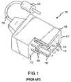
- FIG. 1gives an isometric view of a plug 100 according to the prior art.
- the plug 100has a plurality of metal pins 110 protruding from a flat inner base 112 disposed in a protected inner space 115 formed by a protective hood 117 .
- Different deviceshave different plug configurations with different numbers and placement of pins 110 depending on the types and number of control and data signals required to be transmitted between the device and the computer.
- the different pin configurations of the various plugs 100necessitate the inclusion of various sockets (not shown) located on the computer, or alternatively, on an end of a connecting cable with corresponding configurations of pin receivers to receive the various plugs 100 .
- various socketsnot shown
- control and data signals from the deviceare transmitted over insulated wires inside of a cord 120 to respective pins 110 .
- EMIelectromagnetic interference
- RFIDradio frequency interference
- transient voltagesa ferrite or capacitor structure 122 is placed in the cord 120 .
- FIG. 1also illustrates a negative keyway 125 with a width 133 extending through the thickness 135 of the protective hood 117 from the flat inner base 112 to an outer end 130 of the protective hood 117 .
- This negative keyway 125can be used to prevent a socket from being used with an ill-suited plug.
- the socketshould include a protruding positive keyway with a length less than or equal to the length of the negative keyway 125 , as measured from the outer end 130 of the protective hood to the flat inner base 112 , and a width less than or equal to the width 133 of the keyway 125 .
- the positive keyway on the socketis too long or too wide, it will obstruct the mating of the socket with the plug 100 . Additionally, the positive keyway on the socket must be accurately placed to mate with the negative keyway 125 when the plug 100 mates with the socket. If this does not occur, even positive keyways with proper widths and lengths will obscure the mating of the socket to the plug 100 , and the pins 110 of the plug 100 will not contact the pin receivers of the socket.
- the negative keyway 125has a large shortcoming, however, in that it is of no value in preventing the cross connection of plugs unless it is used in conjunction with sockets having positive keyways. For example, in the description given above, if the socket has no positive keyway it will mate with the plug 100 regardless of the size and location of the negative keyway 125 present on the plug 100 .
- a socketcan be readily indicated as compatible with a certain plug is through color coding.
- compatible plugs and socketsare created to be the same color, enabling users to quickly and easily couple plugs to corresponding sockets by matching their colors.
- This systemis not fail-safe however, and it can be rendered useless by low light situations and scenarios in which users are unable to physically see both the plug and socket (such as when the socket is backed up against a wall adjacent to the computer, or the socket is in a hard to see location).
- the plug 100is held in place by friction between the pins 110 and the corresponding pin receivers in the socket, as well as by friction between the other areas of the socket which contact the plug 100 .
- the cumulative friction between these areasis often quite low, making it correspondingly easy for the plug 100 to be accidentally disengaged from the socket or to slip out of the socket due to factors such as the weight of the cord 120 hanging from the plug 100 , or incidental contact between the plug 100 and objects brushing against it, which is a common occurrence in a busy medical atmosphere.
- slippageonly needs to proceed far enough to pull the pins 110 away from their pin receivers to result in a failure of the connection.
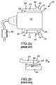
- FIG. 2 agives a top view of a plug 200 similar to plug 100 , but with cantilever latches 210 disposed on its outer sides 220 at a centerline of the thickness of the plug 200 .
- the precise function of these latches 210is illustrated in FIG. 2 b, which provides a cutaway view of an inside portion 221 of the socket engaged with one of the latches 210 .
- the pawls 230 disposed on the end of each latch 210contact a catching device 222 located in the socket.
- a sloping front surface 235 of the pawl 230contacts a sloping receiving surface 237 of the catching device 222 and the force created by this contact initiates a bending of the latch 210 into a free space 238 ( FIG. 2 a ) between the latch body 250 (also shown in FIG. 2 a ) and the body 239 of the plug 200 .
- the plug body 239When coupled, a portion of the plug body 239 extends out of the socket to an extent that sections of the latches 210 are readily accessible to the user. Additionally, as the latch pawl 230 couples with the catching device 222 , the latch 210 snaps out of the free space 238 creating both an audible report and a vibratory indication to the user that the plug 200 has become coupled to the socket.
- the usersqueezes the accessible portions of the latches 210 toward the plug body 239 .
- Thismoves the pawls 230 relative to the plug body 239 , displacing them into the free space 238 .
- the rear vertical surfaces 242 of the pawls 230clear the vertical faces 240 of the catching devices 222 , and the plug 200 may be moved in a direction opposite to direction 233 and be decoupled from the socket.
- Latches 210are somewhat difficult to use however, since their cantilever configuration leaves them especially susceptible to entanglement with objects or wires small enough to fit into the free space 238 . Additionally, the shape of the pawl 230 itself encourages snagging and entanglement with a wide variety of different materials. Such snagging problems can result in damage to the objects which become entangled, as well as deformation or destruction of the latches 210 themselves.
- the present inventionis directed to an apparatus and method for coupling electrical devices through utilization of a socket connector to couple electrical plugs to sockets, which may be mounted on a circuit board.
- the socketmay be positioned on an end of a connecting cable.
- the socket connectormay be secured to the circuit board by a plurality of locking legs disposed on the connector which include anchor pawls operable to fit through openings in the circuit board and secure the legs from being decoupled from the circuit board.
- the socket connectoralso includes at least one socket operable to receive an electrical plug, a socket silo and a rolling latch on the plug.
- the socketcan also include a plurality of pawl receiving chambers sized and configured to receive a pawl disposed on a latch on the plug.
- Each pawl receiving chambermay further include an angled receiving wall operable to engage a surface on the pawl when the plug is coupled to the socket, the slope of the angled wall being proportionate to the pullout force required to withdraw the pawl from the receiving chamber and decouple the plug from the socket.
- the socketmay also include a positive keyway configured to fit within a corresponding negative keyway on a plug to be coupled with the socket.
- the silomay contain a tower having a beveled outer receiving surface including at least one socket for receiving a conductive pin.
- An electrical conductor disposed on the inside of the socketextends from at least about four millimeters below the outer receiving surface to beyond the bottom surface of the support shelf and may be electrically coupled with the conductive pin.
- the silomay also include a support shelf on which the tower is disposed and at least one leg on a bottom surface of the support shelf.
- An open gallery operable to hold a planar filter arraycan be created by the intersection of the bottom surface of the support shelf and the at least one leg.
- the plugincludes a fuselage having a beveled face from which at least one conductive pin extends.
- the plug and its beveled faceare configured to mate with the silo tower and its beveled outer receiving surface.
- Rolling latchesare disposed on a hinged section of the plug with the latches being disposed above a longitudinal centerline of a thickness of the plug.
- the latchesinclude pawls operable to fit within the pawl receiving chambers in the socket and couple the plug to the socket.
- the entire latch and hinged sectionmay rotate into a recessed section on an inside of the plug from an extended to a retracted position.
- a locking portion on the pawlmay be angled to customize a pullout force required to withdraw the plug from the socket.
- FIG. 1is an isometric partial cut away view of an electrical plug with a negative keyway according to the prior art.
- FIG. 2 ais a top view of an electrical connector with cantilever latches according to the prior art.
- FIG. 2 bis a top view of a cutaway section of a socket contacting a latch according to the prior art.
- FIG. 3is an isometric partial cut away view of a multi-contact connector coupled to a circuit board according to an embodiment of the invention.
- FIG. 4is an isometric view of a socket silo according to another embodiment of the invention.
- FIG. 5is an isometric view of a planar filter array according to still another embodiment of the invention.
- FIG. 6is a partial isometric cut-away view of an electrical plug engaged with a socket silo according to an embodiment of the invention.
- FIG. 7is an isometric partial cut-away view of an electrical plug with latches and a negative keyway according to an embodiment of the invention.
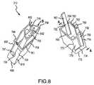
- FIG. 8is an isometric view of two components of an electrical plug according to an embodiment of the invention.
- FIG. 9is an isometric view of a pawl according to an embodiment of the invention.
- the present inventionis generally directed to an apparatus for coupling electronic devices to one another. Many of the specific details of certain embodiments of the invention are set forth in the following description and in FIGS. 3 through 7 c to provide a thorough understanding of such embodiments. One skilled in the art will understand, however, that the present invention may be practiced without several of the details described in the following description.
- FIG. 3is an isometric partial cut-away view of a multi-contact connector coupled to a circuit board according to an embodiment of the invention.
- the multi-contact connector 300includes sockets 302 a–d operable to receive device plugs 310 . Because of the nested design of the sockets 302 a–d in the connector 300 , good access exists to the plugs 310 even when all of the sockets 302 a–d are populated.
- the number of sockets in the multi-contact connector 300can vary from one to as many as are required to perform numerous desired applications. Additionally, the sockets 302 a–d may be arranged in a variety of patterns including, inter alia, staggered placement within the multi-contact connector 300 .
- the multi-contact connector 300may also be comprised of any material that affords structural rigidity, such as heavy gage plastics, which increase the robustness of the connector 300 and allow it to endure heavy field use.
- the multi-contact connector 300may be coupled to a circuit board 330 by a plurality of stabilizing posts 332 extending into holes 334 in the circuit board 330 . Additionally, a plurality of locking legs 336 extend from the multi-contact connector 300 through holes 338 in the circuit board 330 . Each locking leg 336 is inserted through a corresponding hole 338 by pressing the outside surface 342 of the locking leg 336 towards the body 344 of the multi-contact connector 300 and inserting a pawl 346 located at the end of the leg 336 all the way through the hole 338 .
- the outside surface 342 of the leg 336is released, resulting in a rebound of the leg 336 toward its original position relative to the body 344 of the multi-contact connector 300 .
- the outside surface 342 of the legcomes to rest snugly against an inside wall of the hole 338 .
- the pawl 346extends away from the outside surface 342 of the leg 336 along the bottom side 347 of the circuit board 330 .
- the rest of the multi-contact connector 300need not rest directly on the circuit board 330 . Rather, the underside 350 of the multi-contact connector 300 may rest on support shelves 355 b–d located on socket silos 360 b–d . No silo is included in socket 302 a in the interest of graphic clarity.
- FIG. 4gives an isometric view of a socket silo 360 according to an embodiment of the invention.
- the silo 360can be constructed of any resilient insulating material, including plastic.
- the silo 360has a beveled outer receiving surface 401 in which individual receiving sockets 402 are disposed.
- the receiving sockets 402include electric conductors located below the beveled outer receiving surface 401 , which extend through a tower 410 and lower surface 405 of the silo 360 , where they are coupled to bond pads on a circuit board to which the support silo 360 is attached. These conductors are electrically isolated from each other, and are recessed from the outer receiving surface 401 so that the pins with which they are to be coupled must be firmly seated in the sockets before an electrical coupling of the pins and conductors will take place.
- the silo 360 shown in FIG. 4includes thirteen sockets, but one skilled in the art will understand that the number and placement of the receiving sockets 402 may vary.
- the silos 360 , 360 b and 360 d shown in FIGS. 3 and 4have towers 410 with outer surfaces 412 having approximately trapezoidal cross sections. Silos 360 with outer surfaces having other cross sections can also be used, depending on the shape of the inside of the plug to which the silo 360 is to be coupled. The mating of the silos 360 and plugs 310 will be discussed in more detail below in conjunction with FIG. 6 .
- the silo 360has legs 416 extending from the lower surface 405 of the support shelf 355 .
- Protuberances 418may be disposed on the legs 416 to fit into holes on a circuit board and may orient or affix the silo 360 to the circuit board.
- the legs 416can be affixed to the circuit board by any other means known in the art.
- FIG. 5provides an isometric view of a planar filter array 500 according to one embodiment of the invention suitable for use with the open gallery 420 (as shown in FIG. 4 ).
- the planar filter array 500may be comprised of a a ferrite material, or a collection of capacitors or any other electrical assembly desired to be used in conjunction with the conductors before they reach the bonding pads on the circuit board 330 .
- the planar filter array 500includes through holes 502 extending from a lower surface 504 to an upper surface 506 , through which the conductors corresponding to each receiving socket 402 ( FIG. 4 ) pass.
- Positioning pegs 510may be disposed on the planar filter array 500 and used to attach it to corresponding holes or circuit bonding pads in the circuit board 330 or lower surface 405 of the support shelf 355 ( FIG. 4 ).
- the positioning pegs 510may be comprised of a conductive material.
- the planar filter array 500may be attached to either the circuit board 330 or the lower surface 405 of the support shelf 355 ( FIG. 4 ) by any method known in the art. Additionally, it is possible to forego these methods entirely and rely solely on the conductors running from the sockets 402 through the holes to bond pads on the circuit board 330 to keep the planar filter array 500 situated in the open gallery 420 when the silo 360 is coupled to the circuit board 330 .
- FIG. 6is a partial isometric cut-away view showing the interaction of the socket silo 360 engaged with a pin holder portion 600 of a plug 310 and a planar filter array 500 according to an embodiment of the invention.
- the relationship of the pin holder portion 600 to the entire plug 310will be discussed more fully below in the discussion of FIG. 8 .
- the pin holder portion 600is mated with the silo 360 to an extent that a pin 602 disposed within the pin holder portion 600 has entered a socket 402 and has made electrical contact with a conductor (not shown) disposed in the socket 402 . Only one pin 602 has been included in FIG. 6 for the sake of graphic clarity, but typically all of the sockets 402 on the silo 360 are filled with corresponding pins 602 from the pin holder portion 600 .
- the receiving end 605 of the pin holder portion 600is placed over the beveled outer receiving surface 401 of the silo 360 and the pin holder portion 600 is moved in a direction 610 toward the support shelf 355 of the silo 360 .
- An outer sheath 615 of the pin holder portion 600surrounds the tower 410 of the silo 360 , with the inside surface 620 of the sheath 615 being configured to conform to the contours of the outer surface 412 of the tower 410 .
- the inside surface 620 of the sheath 615does not conform to the contours of the outer surface 412 of the tower 410 .
- there is an amount of play between the tower 410 and the plug 310which makes centering the tower 410 difficult and jeopardizes the coupling of the pins 602 into the sockets 402 .
- the playalso allows movement between the pin holder portion 600 and silo 360 after coupling, which can weaken both the sockets 402 and their conductors, as well as damaging the pins 602 and potentially also compromising the connection of the conductors to the circuit board.
- This movement due to play between the tower 410 and plug 310is ameliorated by the beveled outer receiving surface 401 on the tower 410 , which fits snugly into a corresponding beveled coupling surface 630 disposed on the inside of the pin holder portion 600 .
- the matching beveled surfaces 401 , 630also enable the pin holder portion 600 to be easily centered during the mating process described above, maximizing the snugness of the fit between the pin holder portion 600 and the tower 410 , and ensuring clean contact between the pins 602 and the corresponding conductors in sockets 402 . This decreases the chances of pins 602 missing sockets 402 when the pin holder portion 600 is pressed into contact with the tower 410 , which in turn decreases the wear on the pins 602 and the sockets 402 .
- the matching beveled surfaces 401 , 630are also advantageous because of their ability to prevent the use of devices ill-suited for a given socket. For example, when an attempt is made to mate an incorrect device having a standard prior art plug with a flat inner base 112 ( FIG. 1 ) to the silo 360 shown in FIG. 6 , the advancement of the flat inner base 112 in the direction of the support shelf 355 is stopped by a crown 635 located on the beveled outer receiving surface 401 . Because of this crown 635 , some portions of the flat inner space 112 are located farther from the beveled outer receiving surface 401 than others, resulting in a distance to some sockets 402 which is too great to be spanned by some pins 110 on the plug 100 ( FIG. 1 ).
- the pins 110will not be able to make contact with some connectors inside the sockets 402 , and no electrical coupling of the plug 100 to the silo 360 will take place.
- ill-suited devices not having plugs with correctly beveled coupling surfaces 630will not be able to couple with the beveled outer receiving surface 401 on the silo 360 , thus avoiding damage to the devices and to the computer to which the silo 360 is electrically coupled.
- FIG. 7is an isometric partial cut-away view of a plug 310 with rolling latches 702 and a negative keyway 704 according to an embodiment of the invention.
- the negative keyway 704extends from the receiving end 605 of the pin holder portion 600 towards the body 725 of the plug 310 and has width 706 .
- the negative keyway 704is a notch formed on the outer surface 708 of the sheath 615 of the pin holder portion 600 .
- the keyway 704can also extend all the way through the outer sheath 615 .
- the negative keyway 704is uniquely positioned on the outer surface 708 of the pin holder portion 600 to coincide with a corresponding positive keyway 710 c ( FIG. 3 ) formed on an inner wall 712 of a socket 302 c .
- the positive keyway 710 chas a length and width similar to those of the negative keyway 704 such that the positive keyway 710 c fits entirely within the negative keyway 704 when the plug 310 is mated to the socket 302 c , as shown in FIG. 3 .
- the relationship between the negative keyway 704 formed on the pin holder portion 600 and the positive keyway 710 c formed on the socket 302 cis important for several reasons.
- the compatibility of a plug 310 with a socket 302can be dictated by the placement of the positive keyway 710 c on the socket 302 .
- the positive keyway 710 cprevents cross connecting of plugs ill-suited to be coupled with the socket 302 c .
- the positive keyway 710 cis located toward the right hand side of socket 302 c .
- a plug 310in order for a plug 310 to mate with the socket 302 c , it must have a negative keyway with a length and thickness great enough to accept the positive keyway 710 c , and the negative keyway must be located on the right hand side of the plug to match up with the positive keyway 710 c when the plug and socket 302 c are mated.
- a correctly sized negative keyway that is not properly positioned on the plugwill not enable the plug to mate with the socket 302 c .
- the plug 310 shown in FIG. 7will only be compatible with the socket 302 c .
- plug 310will not be able to mate with socket 302 a because the positive keyway 702 a in socket 302 a is located too far to the left.
- positive keyways 710 having different lengths and widthscan also be used to block certain plugs from mating with certain sockets 302 .
- negative keyways 704will be ill-suited for mating unless they have a length and width 706 great enough to accept the corresponding length and width 706 of a positive keyway 710 .
- One advantage of this techniqueis that plugs with wide or multiple negative keyways 704 will be compatible with any socket 302 having a narrower, or single positive keyway 710 , thus producing various subgroups.
- a connector having twin negative keyways corresponding to the A and C positions, and another connector having twin negative keyways C and Emay be inserted into compatible sockets having identical keyway configurations, and would also be accepted into a connector having a positive keyway at the C position.
- twin negative connectorsmay be accommodated by a single connector having a fixed configuration to yield a universal connector having a single positive keyway.
- the single positive keyway configurationwould still not compatibly mate with other connectors having a more restrictive keyway configuration, such as a connector having two positive keyways.
- the positive and negative keyways 710 , 704are their stabilizing influence against relative motion between a plug 310 and socket 302 when they are mated together.
- the positive keyway 710fits snugly within the negative keyway 704 , thus obstructing any rotation or sliding of the plug 310 while it is within the socket 302 .
- the placement of each positive keyway 710acts as a visual indication of the compatibility of a plug 310 with a socket 302 in which the positive keyway 710 is found. In order to quickly determine the correct orientation of the plug 310 relative to the socket 302 , the user needs only to match the side of the plug 310 having the negative keyway 704 with the side of the socket having the positive keyway 710 .
- Another technique to aid users in quickly identifying compatible plugs 310 and sockets 302is the color coding of compatible components.
- only the pin holding portion 600 of the plug 310 near to its receiving end 605is colored.
- each silo 360is also uniquely colored.
- a user wishing to couple a device into the multi-contact connector 300need only match the color on the pin holder 600 of the device's plug 310 with that of a silo 360 .
- the plug 310can be pushed into the socket 302 and mated.
- the colored portion of the silo 360is obscured by both the sheath 615 of the plug 310 and the underside 350 of the connector 300 , and the colored portion of the plug 310 is disposed within the socket 302 , little color can be seen once the plug 310 is mated to the socket 302 . As a result, there is only a low level of visual noise when the connector 300 is highly populated with colored plugs 310 mated to its sockets 302 .
- FIG. 8is an isometric view of two components of an electrical plug according to an embodiment of the invention, and will be used to illustrate the relationship between the pin holder portion 600 and a latch holder portion 752 which form the body of plug 310 .
- the pin holder portion 600has two opposing ends—the receiving end 605 and a back end 754 .
- Pins 602extend from the beveled coupling surface 630 (obscured by the outer sheath 615 in FIG. 8 but shown clearly in FIGS. 6 and 7 ) through the body of the pin holder portion 600 and beyond a rear face 755 of the pin holder portion 600 .
- the outer sheath 615extends beyond the tips of the pins 602 for set back safety.
- electrically energized contactsmust be recessed within a silo at least about four millimeters in order to comply with IEC-601.
- a siloat least about four millimeters in order to comply with IEC-601.
- other lengths for the outer sheath 615can also be used successfully with the invention.
- the pin holder portion 600is coupled to the latch holder portion 752 by inserting the back end 754 of the pin holder portion 600 through an opening defined by a mating face 757 of the latch holder 752 , and pressing the holders 600 and 752 together so that the latches 702 slide along support shelves 758 formed on the pin holder 600 , until the mating face 757 contacts a mating ridge 759 on the pin holder portion 600 .
- the mating ridge 759has apertures 761 into which small extensions 763 on the mating face 757 snugly fit.
- apertures 761 and extensions 763 on the pin holder 600 and latch holder 752may be reversed.
- apertures 761 and extensions 736may be omitted entirely and the pin holder portion 600 and the latch holder portion 752 can be coupled to one another by any other means known in the art, including, inter alia, glues and other bonding techniques.
- the portions of the pins 602 extending beyond the rear face 755are coupled to individual wires in a cord 756 ( FIG. 7 ), and a cord interface portion 765 ( FIG. 7 ) is coupled to the back face 772 and back end 754 of the latch holder portion 752 and the pin holder portion 600 , respectively.
- the resultis a plug 310 configured like that shown in FIG. 7 .
- each latch 702is formed on the latch holder portion 752 , and has a cantilever portion 767 extending beyond the mating face 757 which ends in a pawl 769 .
- a section 770 of the latch holder portion 752 on which the latch 702 is formedhas three sides, with only one side 773 being attached to the rest of the holder portion 752 .
- a channel 774 through the thickness of the holder portion 752separates the sides of the section 770 from the holder portion 752 , enabling the section 770 to pivot about the side 773 .
- the latches 702when squeezed toward each other by a user, they pivot elastically about side 773 toward the space on the inside of the holder portion 752 . Because the pivot side 773 pivots at 90 degrees to the direction of forces involved in retaining the latch, the effect of long-term material fatiguing on the pivot side 773 due to the forces generated by latching or latch retention are ameliorated.
- recessed sections 776 on the pin holder portion 600allow the latches 702 to pivot inward towards a stop surface 777 to arrive at a retracted position.
- its pawl 769when a latch 702 is in its fully retracted position, its pawl 769 is entirely recessed within the recessed section 776 and does not extend beyond the surface of the sheath section 615 .
- the latches 702 in FIGS. 7 and 8are shown in an extended position in which the pawls 769 extend considerably outside of the sheath 615 of the plug 310 . In both the retracted or the extended positions, however, the entire length of the latch 702 , including the pawl 769 , is at least partially buried in the recessed section 776 , effectively protecting the latch 702 from becoming snagged in objects passing by the latch 702 . In addition, the entire length of the latch 702 is supported—either by being attached to a section 770 of the latch holder portion 752 , or by resting on, or slightly above, the support shelf 758 found on the pin holder portion 600 . This increases the durability of the latches 702 , and decreases the potential for deformation or failure of the latches 702 due to loading or incidental contact with objects brushing against the latches 702 .
- latches 702Of additional importance to the functioning of the latches 702 is the placement of the latches 702 and the recessed sections 776 above the centerlines b—b and a—a of the pin holder and latch holder portions 600 , 752 , respectively. Placing the latches 702 and the recessed portions 776 above the plug centerline is superior to the placement of conventional latches at the plug centerline, since the latches 702 are better able to support the weight, and thus counteract the moment of a cord hanging from a plug to which the latches 702 are attached. As best shown in FIG.
- the latches 702 and the hanging portion of the cord 756are on opposite sides of the plug centerline c—c.
- the pawls 769are higher on the socket 302 c than they would be if the latches 702 were placed at the centerline c—c. This distance from the centerline c—c increases the capacity of the pawl 769 to resist the torque created by the hanging cord 756 .
- FIG. 9shows the pawl 769 from a top isometric view.
- the negative keyway 704 on the plug 310 and the positive keyway 710 c on the connector 300must be lined up, and the receiving end 605 of the plug 310 must be displaced towards the underside 350 of the multi-contact connector 300 .
- the positive keyway 710 cslides into the negative keyway 704 and guides the plug 310 into the socket 302 c .
- the pawls 769 on the latches 702approach the upper surface 778 of the connector 300 .
- the body 725 of the plug 310is sized to ensure a snug fit within the socket 302 c.
- the insertion of the plug 310 into the socket 302 cis blocked, however, when the latches 702 are in the extended position by pawls 769 which contact the upper surface 778 of the connector 300 .
- the pawls 769may be designed so that the upper surface 778 contacts an angled receiving portion 779 or a flat front portion 780 ( FIG. 9 ) of the pawl 769 .
- the flat front portion 780is wide enough to protrude from the recessed section 776 ( FIG. 6 )
- the progress of the plug 310 into the socket 302 cwill be stopped until enough pressure is exerted on the latch 702 to force the cantilever portion 767 ( FIG.
- the pawl 769on which the pawl 769 is disposed to rotate into the recessed section 776 .
- insertion of the pawl 769can commence.
- the force required to insert the plug 310will vary in proportion to the slope of the angled receiving portion 779 . For example, if the angled receiving portion 779 makes a 45 degree angle with the flat front portion 780 , the force required to insert the plug 310 (and thus instigate rotation of the latch 702 into the recessed section 776 ) will be less than if the slope of the angled receiving portion 779 makes a 20 degree angle with the flat front portion 780 .
- the receiving portion 779will be parallel to the flat front portion 780 , and it will fully block the insertion of the pawl 769 into the socket 302 c.
- a designermay vary the force required to insert a plug 310 by varying the slope of the angled receiving portion 779 .
- the pawl 769travels toward the support shelf 355 c .
- the angled receiving portion 779transitions into a cambered section 781 and ends in a transition point 782 .
- a pullout face 783is encountered which slopes toward the body 725 of the plug 310 before encountering a trailing edge 784 and a steep locking portion 785 , which leads to the notch floor 786 .
- the latch 702begins rebounding out of the recessed section 776 and rotates toward its extended position. This rotation quickly comes to fruition when the trailing edge 784 of the pullout face 783 clears a corner 787 c on the inside wall of the socket 302 c and begins sliding along an angled receiving wall 788 c of the pawl receiving chamber 790 c .
- no plugs 310have been drawn in sockets 302 a , 302 b and 302 d , enabling a clear view of pawl receiving chambers 790 a , 790 d with structures similar to the pawl receiving chamber 790 c.
- the latch 702continues its rotation out of the cutaway section 776 ( FIG. 8 ) towards its extended position.
- the pullout face 783comes to rest snugly against the angled receiving wall 788 c , hindering the withdrawal of the latch 702 and thus the removal of the plug 310 from the socket 302 c .
- the receiving end 605 of the plug 310preferably rests on the surface of a floor 888 of the socket 302 c (as shown in FIG.
- a top surface 793 of the pawl 769rests against a side wall of the receiving chamber similar to the sidewalls 794 a , 794 d .
- the broad area of the top surface 793allows the latch 702 to effectively resist forces placed on the latch 702 , including the weight of the cord 756 hanging from the plug 310 .
- the support shelf on the silo 355 d(as shown in FIG. 3 ) generally presses against the underside surface 350 of the connector 300 .
- the silo 355 dis thus captured by the hooked circuit board, the silo pins that are soldered to the circuit board pads, and the cutout in the underside surface 350 of the connector 300 .
- cambered section 781 on the pawl 769acts as an important additional safety mechanism to guard against the insertion of ill-suited devices into the socket 302 c .
- the top edge 796 of the pawl 769swings through a wider arc than the lower end 798 of the pawl 769 .
- the top edge 796swings farther into the recessed section 776 ( FIG. 8 ) than does the lower end 798 .
- cambered section 781is needed to reduce the height of the pawl 769 towards its lower end 798 , so that in its recessed position none of the pawl 769 will extend out of the recessed section 776 beyond the sheath 615 ( FIG. 8 ).
- a latch 702 not having a cambered section 781would have a lower end 798 protruding too far beyond the sheath 615 , obstructing insertion of the plug 310 into the socket 302 c.
- cambered section 781results in a reduced and more uniform spreading of surface wear on both the pawl 769 and the upper surface 778 as the pawl 769 is inserted and withdrawn from the socket 302 c .
- Thisis in contrast to the high localized surface wear that would occur at a protruding corner on the pawl 769 which would exist if the cambered section 781 was not formed in the pawl, as well as the increased wear on the upper surface 778 contacting the corner during insertion and retraction of the pawl 769 from the socket 302 c.
- the plug 310is held snugly in the socket 302 c by a combination of factors, including: (1) the shape of the plug body 725 being matched with the socket's shape; (2) the trailing edges 784 and pullout faces 783 of the latches 702 exerting force against the angled receiving walls 788 c , and the top surfaces 793 of the pawls 769 resting against the side walls of the receiving chambers 792 c; and (3) the receiving end 605 of the plug 310 resting on the surface of the floor 888 of the socket 302 c (as shown in FIG. 3 ).
- the plug 310is also held firmly in the socket 302 c by the fit of the outer surface 412 of the tower 410 of the silo 360 c (not shown) within the inside surface 620 of the sheath 615 of the plug 310 ( FIG. 6 ). Moreover, movement between the plug 310 and socket 302 c is also arrested by the beveled outer receiving surface 401 on the tower 410 , which fits snugly into a corresponding beveled coupling surface 630 disposed on the inside of the plug 310 , and the pins 602 seated in the sockets 402 (as discussed in conjunction with FIG. 6 above).
- One method of withdrawing the plug 310involves applying pressure to the upper bodies 799 of the latches 702 , and urging them to rotate in towards a retracted position. When this rotation has proceeded far enough that the pullout faces 783 and trailing edges 784 of the pawls 769 no longer contact the angled receiving wall 788 c , and will not contact the corner 787 c on the inside wall of the socket 302 c , the plug 310 may be pulled out of the socket 302 c by the user.
- the angled receiving wall 788 cmay be designed to require a predetermined amount of force to effect the uncoupling of the plug 310 from the socket 302 c . If the angled receiving wall 788 c is horizontal, similar to the upper surface 778 of the connector 300 as shown in FIG. 3 , then the pullout force required to decouple the plug 310 from the socket 302 c is maximized.
- each socket 302 cmay be specifically engineered for each device which is to be attached to it.
- the pullout faces 783 of the latches 702may also be engineered to customize the pullout force required to decouple the plug 310 from the socket 302 .
- pullout face 783In order to effect a lesser pullout force, pullout face 783 must be angled away from the steep locking portion 785 . In contrast, to effect the maximum pullout force, the pullout face 783 must be made parallel to the steep locking portion 785 .
- the ability to engineer the pullout forceexists for any plug 310 or socket 302 , and as a result, designers need not rely solely on frictional forces between the pins 602 and silos 360 for retention of a plug 310 in a socket 302 .
- the pullout forcemay be engineered to be the same for a plug 310 regardless of whether it is fully populated or only partially populated with pins 602 .
Landscapes
- Details Of Connecting Devices For Male And Female Coupling (AREA)
- Measuring And Recording Apparatus For Diagnosis (AREA)
Abstract
Description
Claims (9)
Priority Applications (2)
| Application Number | Priority Date | Filing Date | Title |
|---|---|---|---|
| US11/258,648US7117590B2 (en) | 2003-08-19 | 2005-10-25 | Latching medical patient parameter safety connector and method |
| US11/478,511US7258566B2 (en) | 2003-08-19 | 2006-06-28 | Latching medical patient parameter safety connector and method |
Applications Claiming Priority (2)
| Application Number | Priority Date | Filing Date | Title |
|---|---|---|---|
| US10/644,608US7144268B2 (en) | 2003-08-19 | 2003-08-19 | Latching medical patient parameter safety connector and method |
| US11/258,648US7117590B2 (en) | 2003-08-19 | 2005-10-25 | Latching medical patient parameter safety connector and method |
Related Parent Applications (1)
| Application Number | Title | Priority Date | Filing Date |
|---|---|---|---|
| US10/644,608DivisionUS7144268B2 (en) | 2003-08-19 | 2003-08-19 | Latching medical patient parameter safety connector and method |
Related Child Applications (1)
| Application Number | Title | Priority Date | Filing Date |
|---|---|---|---|
| US11/478,511DivisionUS7258566B2 (en) | 2003-08-19 | 2006-06-28 | Latching medical patient parameter safety connector and method |
Publications (2)
| Publication Number | Publication Date |
|---|---|
| US20060040542A1 US20060040542A1 (en) | 2006-02-23 |
| US7117590B2true US7117590B2 (en) | 2006-10-10 |
Family
ID=34194129
Family Applications (6)
| Application Number | Title | Priority Date | Filing Date |
|---|---|---|---|
| US10/644,608Expired - Fee RelatedUS7144268B2 (en) | 2003-08-19 | 2003-08-19 | Latching medical patient parameter safety connector and method |
| US11/258,692Expired - Fee RelatedUS7198502B2 (en) | 2003-08-19 | 2005-10-25 | Latching medical patient parameter safety connector and method |
| US11/258,648Expired - Fee RelatedUS7117590B2 (en) | 2003-08-19 | 2005-10-25 | Latching medical patient parameter safety connector and method |
| US11/259,535Expired - Fee RelatedUS7264510B2 (en) | 2003-08-19 | 2005-10-25 | Latching medical patient parameter safety connector and method |
| US11/258,693Expired - Fee RelatedUS7179113B2 (en) | 2003-08-19 | 2005-10-25 | Latching medical patient parameter safety connector and method |
| US11/478,511Expired - Fee RelatedUS7258566B2 (en) | 2003-08-19 | 2006-06-28 | Latching medical patient parameter safety connector and method |
Family Applications Before (2)
| Application Number | Title | Priority Date | Filing Date |
|---|---|---|---|
| US10/644,608Expired - Fee RelatedUS7144268B2 (en) | 2003-08-19 | 2003-08-19 | Latching medical patient parameter safety connector and method |
| US11/258,692Expired - Fee RelatedUS7198502B2 (en) | 2003-08-19 | 2005-10-25 | Latching medical patient parameter safety connector and method |
Family Applications After (3)
| Application Number | Title | Priority Date | Filing Date |
|---|---|---|---|
| US11/259,535Expired - Fee RelatedUS7264510B2 (en) | 2003-08-19 | 2005-10-25 | Latching medical patient parameter safety connector and method |
| US11/258,693Expired - Fee RelatedUS7179113B2 (en) | 2003-08-19 | 2005-10-25 | Latching medical patient parameter safety connector and method |
| US11/478,511Expired - Fee RelatedUS7258566B2 (en) | 2003-08-19 | 2006-06-28 | Latching medical patient parameter safety connector and method |
Country Status (6)
| Country | Link |
|---|---|
| US (6) | US7144268B2 (en) |
| EP (1) | EP1661212A4 (en) |
| JP (1) | JP2007503095A (en) |
| CN (3) | CN101615738A (en) |
| RU (1) | RU2345457C2 (en) |
| WO (1) | WO2005020374A2 (en) |
Cited By (27)
| Publication number | Priority date | Publication date | Assignee | Title |
|---|---|---|---|---|
| US7658652B2 (en) | 2006-09-29 | 2010-02-09 | Nellcor Puritan Bennett Llc | Device and method for reducing crosstalk |
| US7676253B2 (en) | 2005-09-29 | 2010-03-09 | Nellcor Puritan Bennett Llc | Medical sensor and technique for using the same |
| US7887345B2 (en) | 2008-06-30 | 2011-02-15 | Nellcor Puritan Bennett Llc | Single use connector for pulse oximetry sensors |
| US8175671B2 (en) | 2006-09-22 | 2012-05-08 | Nellcor Puritan Bennett Llc | Medical sensor for reducing signal artifacts and technique for using the same |
| US8190225B2 (en) | 2006-09-22 | 2012-05-29 | Nellcor Puritan Bennett Llc | Medical sensor for reducing signal artifacts and technique for using the same |
| US8396527B2 (en) | 2006-09-22 | 2013-03-12 | Covidien Lp | Medical sensor for reducing signal artifacts and technique for using the same |
| US8568160B2 (en) | 2010-07-29 | 2013-10-29 | Covidien Lp | ECG adapter system and method |
| US8634901B2 (en) | 2011-09-30 | 2014-01-21 | Covidien Lp | ECG leadwire system with noise suppression and related methods |
| US8668651B2 (en) | 2006-12-05 | 2014-03-11 | Covidien Lp | ECG lead set and ECG adapter system |
| US8690611B2 (en) | 2007-12-11 | 2014-04-08 | Covidien Lp | ECG electrode connector |
| US8694080B2 (en) | 2009-10-21 | 2014-04-08 | Covidien Lp | ECG lead system |
| US8821405B2 (en) | 2006-09-28 | 2014-09-02 | Covidien Lp | Cable monitoring apparatus |
| USD728483S1 (en) | 2013-10-01 | 2015-05-05 | Covidien Lp | Sensor connector |
| USD728484S1 (en) | 2013-10-01 | 2015-05-05 | Covidien Lp | Sensor connector |
| USD737979S1 (en) | 2008-12-09 | 2015-09-01 | Covidien Lp | ECG electrode connector |
| USD756817S1 (en) | 2015-01-06 | 2016-05-24 | Covidien Lp | Module connectable to a sensor |
| US9408546B2 (en) | 2013-03-15 | 2016-08-09 | Covidien Lp | Radiolucent ECG electrode system |
| US9408547B2 (en) | 2011-07-22 | 2016-08-09 | Covidien Lp | ECG electrode connector |
| USD771818S1 (en) | 2013-03-15 | 2016-11-15 | Covidien Lp | ECG electrode connector |
| USD779432S1 (en) | 2015-09-17 | 2017-02-21 | Covidien Lp | Sensor and connector |
| USD779433S1 (en) | 2015-09-17 | 2017-02-21 | Covidien Lp | Sensor connector cable |
| US9614337B2 (en) | 2014-06-19 | 2017-04-04 | Covidien Lp | Multiple orientation connectors for medical monitoring systems |
| USD784931S1 (en) | 2015-09-17 | 2017-04-25 | Covidien Lp | Sensor connector cable |
| USD790069S1 (en) | 2015-11-02 | 2017-06-20 | Covidien Lp | Medical sensor |
| US9693701B2 (en) | 2013-03-15 | 2017-07-04 | Covidien Lp | Electrode connector design to aid in correct placement |
| USD862709S1 (en) | 2017-09-20 | 2019-10-08 | Covidien Lp | Medical sensor |
| US20220396219A1 (en)* | 2021-06-11 | 2022-12-15 | Yazaki Corporation | Unauthorized connection detecting device |
Families Citing this family (28)
| Publication number | Priority date | Publication date | Assignee | Title |
|---|---|---|---|---|
| FR2871955B1 (en)* | 2004-06-18 | 2006-09-29 | Cie Deutsch Societe Par Action | SYSTEM FOR AUTOMATIC CONNECTION OF TWO ELECTRIC CIRCUITS OF A VEHICLE |
| US7725994B2 (en)* | 2005-01-28 | 2010-06-01 | Ykk Corporation | Buckle, injection molding die and injection molding method |
| JP4579021B2 (en)* | 2005-03-23 | 2010-11-10 | ヒロセ電機株式会社 | Electrical connector |
| FR2894393B1 (en)* | 2005-12-06 | 2008-03-14 | Connecteurs Electr Deutsh Soc | "ELECTRICAL CONNECTOR" |
| US7802933B2 (en)* | 2005-12-23 | 2010-09-28 | Eastman Kodak Company | Thermal printer cartridge with energy absorbing features |
| DE202006011613U1 (en)* | 2006-07-29 | 2006-09-28 | Man Roland Druckmaschinen Ag | Printing-machine coupling system for coupling supply lines to a printing-machine module couples especially to an inking system or a dampening system |
| US20080057767A1 (en) | 2006-08-10 | 2008-03-06 | O'rourke Kevin | Electrical adaptor having an anchor |
| US20080299811A1 (en)* | 2007-05-30 | 2008-12-04 | Battista Paul F | Power inlets and power connectors |
| DE102007027430A1 (en)* | 2007-06-14 | 2008-12-24 | Tyco Electronics Amp Gmbh | Holder of two plugs |
| US7435112B1 (en)* | 2008-02-08 | 2008-10-14 | Tyco Electronics Corporation | Electrical connector having a mechanical mating cycle limitation |
| GB2463468C (en)* | 2008-09-11 | 2016-07-27 | Burland Technology Solutions Ltd | Locking power connector apparatus |
| US7972164B2 (en)* | 2009-03-24 | 2011-07-05 | Tyco Electronics Corporation | Connector assembly with a latch |
| EP2449630B1 (en) | 2009-07-01 | 2016-05-11 | Koninklijke Philips N.V. | Low cost-low profile lead set connector |
| WO2011015923A1 (en)* | 2009-08-07 | 2011-02-10 | Panasonic Electric Works Co., Ltd. | Plug |
| US8376955B2 (en)* | 2009-09-29 | 2013-02-19 | Covidien Lp | Spectroscopic method and system for assessing tissue temperature |
| JP5182893B2 (en)* | 2009-11-17 | 2013-04-17 | Nttエレクトロニクス株式会社 | Optical connector plug |
| US8235748B2 (en)* | 2009-11-30 | 2012-08-07 | Cooper Technologies Company | External quick connect modular plug for a wiring device |
| CN102201621A (en)* | 2010-03-25 | 2011-09-28 | 深圳富泰宏精密工业有限公司 | Battery connector and electronic device applying same |
| CN102456985A (en)* | 2010-10-18 | 2012-05-16 | 鸿富锦精密工业(深圳)有限公司 | Fixed seat |
| CN102544917A (en)* | 2010-12-20 | 2012-07-04 | 鸿富锦精密工业(深圳)有限公司 | Electric connector |
| EP2486885B1 (en)* | 2011-02-09 | 2013-05-01 | Erbe Elektromedizin GmbH | Universal slide-on |
| HUE050214T2 (en)* | 2012-02-16 | 2020-11-30 | Md Elektronik Gmbh | Cable for transferring signals |
| US9246242B2 (en)* | 2012-09-05 | 2016-01-26 | Hubbell Incorporated | Push wire connector having a rotatable release member |
| TWM458000U (en)* | 2013-01-11 | 2013-07-21 | Molex Taiwan Ltd | Electrical connection device |
| CN106463871B (en) | 2014-04-10 | 2019-05-17 | 施恩禧电气有限公司 | Electrical connection system with ring contact |
| US11258202B2 (en)* | 2019-10-24 | 2022-02-22 | Jonathon R. Weeks | Secure outlet device and method |
| US11557848B2 (en) | 2020-12-04 | 2023-01-17 | Biosense Webster (Israel) Ltd. | High-density connector |
| DE102021108763A1 (en)* | 2021-04-08 | 2022-10-13 | Phoenix Contact Gmbh & Co. Kg | Terminal for connecting an electrical conductor |
Citations (41)
| Publication number | Priority date | Publication date | Assignee | Title |
|---|---|---|---|---|
| US2989784A (en)* | 1957-10-04 | 1961-06-27 | Bell Telephone Labor Inc | Method of forming a plug of high melting point plastic bonded to a low melting point plastic |
| US3390369A (en)* | 1966-01-05 | 1968-06-25 | Killark Electric Mfg Company | Electric plug or receptacle assembly with interchangeable parts |
| US3639950A (en) | 1968-09-13 | 1972-02-08 | Itt | Latching device |
| US4056298A (en)* | 1976-10-07 | 1977-11-01 | Automation Industries, Inc. | Electrical connector with coupling assembly breech retaining means |
| US4066315A (en)* | 1976-07-26 | 1978-01-03 | Automation Industries, Inc. | Electrical connector with arcuate detent means |
| US4074927A (en)* | 1976-07-26 | 1978-02-21 | Automation Industries, Inc. | Electrical connector with insert member retaining means |
| US4079343A (en) | 1975-01-08 | 1978-03-14 | Bunker Ramo Corporation | Connector filter assembly |
| US4183605A (en)* | 1976-07-26 | 1980-01-15 | Automation Industries, Inc. | Electrical connector with arcuate detent means |
| US4211461A (en) | 1978-11-27 | 1980-07-08 | Industrial Electronic Hardware Corp. | Axially mating cable connector |
| US4265503A (en)* | 1979-12-20 | 1981-05-05 | Automation Industries, Inc. | Aircraft/pylon multi-contact electrical connector |
| US4277125A (en)* | 1979-07-12 | 1981-07-07 | Automation Industries, Inc. | Enhanced detent guide track with dog-leg |
| US4329665A (en) | 1979-05-09 | 1982-05-11 | Matsushita Electric Industrial Company, Limited | Noise suppressing connector |
| US4473755A (en) | 1981-04-10 | 1984-09-25 | Nissan Motor Company, Limited | Device for preventing noise leakage and manufacturing method of the device |
| USRE31995E (en)* | 1979-07-12 | 1985-10-01 | Automation Industries, Inc. | Enhanced detent guide track with dog-leg |
| US4639061A (en) | 1984-11-19 | 1987-01-27 | Itt Corporation | Environmentally sealed connector |
| US4707048A (en) | 1986-11-03 | 1987-11-17 | Amphenol Corporation | Electrical connector having means for protecting terminals from transient voltages |
| US4784618A (en) | 1986-05-08 | 1988-11-15 | Murata Manufacturing Co., Ltd. | Filter connector device |
| US5161996A (en) | 1991-07-26 | 1992-11-10 | Amp Incorporated | Header assembly and alignment assist shroud therefor |
| US5282757A (en) | 1991-05-16 | 1994-02-01 | Yazaki Corporation | Connector |
| US5295866A (en)* | 1990-10-09 | 1994-03-22 | Kroger Roy E | Insert retention gas tight seal for electrical connector and method of making same |
| US5496190A (en) | 1993-09-10 | 1996-03-05 | Connecteurs Cinch | Electrical connector casings |
| US5562498A (en) | 1994-12-21 | 1996-10-08 | Delco Electronics Corp. | Flexible capacitor filter |
| US5788527A (en) | 1991-04-04 | 1998-08-04 | Magnetek, Inc. | Electrical connector with improved safety latching for a fluorescent-lighting ballast |
| US5830016A (en) | 1997-01-29 | 1998-11-03 | Chuang; Johnson | Interference-proof device for electric connector |
| US5842888A (en) | 1994-10-31 | 1998-12-01 | Berg Technology, Inc. | Low cost filtered and shielded electronic connector |
| US6022246A (en) | 1998-05-08 | 2000-02-08 | Hon Hai Precision Ind. Co., Ltd. | Arrangement for preventing mis-mating of connector assembly |
| US6027359A (en) | 1996-10-07 | 2000-02-22 | Yazaki Corporation | Structure for preventing looseness of an electrical connector |
| US6050850A (en) | 1997-08-14 | 2000-04-18 | The Panda Project | Electrical connector having staggered hold-down tabs |
| US6155864A (en) | 1998-06-16 | 2000-12-05 | Smk Corporation | Connector locking structure |
| US6159049A (en) | 1998-12-07 | 2000-12-12 | Framatone Connectors Interlock, Inc. | Electrical contact and bandolier assembly |
| US6203353B1 (en) | 1999-11-12 | 2001-03-20 | Hon Hai Precision Ind. Co., Ltd. | Electrical connector with passive clip |
| US6302744B1 (en) | 1998-10-13 | 2001-10-16 | 3M Innovative Properties Company | Connector system with polarizing key mechanism |
| US6334785B2 (en)* | 2000-03-10 | 2002-01-01 | Yazaki Corporation | Connector sealing structure |
| US6364718B1 (en) | 2001-02-02 | 2002-04-02 | Molex Incorporated | Keying system for electrical connector assemblies |
| US6464403B1 (en) | 1999-02-12 | 2002-10-15 | Huber & Suhner Ag | Optical connector |
| US6467165B1 (en) | 1998-12-07 | 2002-10-22 | Frametome Connectors Interlock Inc. | Filtered electrical connector assembly having a contact and filtering circuit subassembly |
| US6726495B2 (en) | 2001-09-26 | 2004-04-27 | Amphenol-Tuchel Electronics Gmbh | Insulating body |
| US6746284B1 (en) | 2003-10-02 | 2004-06-08 | Hon Hai Precision Ind. Co., Ltd. | Electrical connector assembly having signal and power terminals |
| US6840789B2 (en) | 2002-11-19 | 2005-01-11 | Sumitomo Wiring Systems, Ltd. | Connector and a method of assembling it |
| US6848938B2 (en) | 2002-05-30 | 2005-02-01 | Sumitomo Wiring Systems, Ltd. | Panel-mountable part and method of dismounting such a panel-mountable part |
| US6863555B2 (en) | 2000-02-22 | 2005-03-08 | Yoshinobu Ito | Power-Cord Connecting Set |
Family Cites Families (18)
| Publication number | Priority date | Publication date | Assignee | Title |
|---|---|---|---|---|
| US3328744A (en) | 1964-12-14 | 1967-06-27 | Amp Inc | Corona resistant lead and terminal assembly |
| JPS5441894Y2 (en)* | 1975-06-05 | 1979-12-06 | ||
| US4464403A (en)* | 1983-02-03 | 1984-08-07 | General Foods Corporation | Instant pudding composition containing cocoa and process |
| GB2146496B (en)* | 1983-09-09 | 1986-11-26 | Mitutoyo Mfg Co Ltd | Cable connecting device |
| SU1229868A1 (en)* | 1984-08-13 | 1986-05-07 | Предприятие П/Я Г-4778 | Electric connector |
| JPH0328540U (en)* | 1989-07-20 | 1991-03-22 | ||
| RU2044375C1 (en)* | 1992-01-09 | 1995-09-20 | Александр Васильевич Медведев | Coaxial connector |
| DE4301504C2 (en)* | 1993-01-21 | 1996-10-31 | Escha Bauelemente Gmbh | Electrical connector |
| JP3064176B2 (en)* | 1994-03-08 | 2000-07-12 | 矢崎総業株式会社 | Connector unlock structure |
| JP3180016B2 (en) | 1996-02-08 | 2001-06-25 | 矢崎総業株式会社 | Half mating prevention connector |
| JPH09330769A (en)* | 1996-06-07 | 1997-12-22 | Yazaki Corp | connector |
| RU2136092C1 (en)* | 1998-07-10 | 1999-08-27 | Открытое акционерное общество "Ракетно-космическая корпорация "Энергия" им.С.П.Королева" | Plug connector |
| JP2000113925A (en)* | 1998-10-08 | 2000-04-21 | Amp Japan Ltd | Board mount connector |
| JP3648432B2 (en) | 2000-05-25 | 2005-05-18 | 矢崎総業株式会社 | Inertia lock connector |
| WO2002039550A2 (en)* | 2000-11-08 | 2002-05-16 | Stephen Craig Le Roux | The identification of electrical plugs |
| JP3806926B2 (en) | 2002-03-01 | 2006-08-09 | 住友電装株式会社 | connector |
| JP2004095346A (en) | 2002-08-30 | 2004-03-25 | Tyco Electronics Amp Kk | Connector assembly and connector for use with the same |
| US6726492B1 (en)* | 2003-05-30 | 2004-04-27 | Hon Hai Precision Ind. Co., Ltd. | Grounded electrical connector |
- 2003
- 2003-08-19USUS10/644,608patent/US7144268B2/ennot_activeExpired - Fee Related
- 2004
- 2004-08-12CNCN200910140173Apatent/CN101615738A/enactivePending
- 2004-08-12WOPCT/US2004/026280patent/WO2005020374A2/enactiveApplication Filing
- 2004-08-12EPEP04781031Apatent/EP1661212A4/ennot_activeWithdrawn
- 2004-08-12CNCN200910140172Apatent/CN101615742A/enactivePending
- 2004-08-12RURU2006108521/09Apatent/RU2345457C2/ennot_activeIP Right Cessation
- 2004-08-12JPJP2006523937Apatent/JP2007503095A/enactivePending
- 2004-08-12CNCNA2004800307457Apatent/CN1906815A/enactivePending
- 2005
- 2005-10-25USUS11/258,692patent/US7198502B2/ennot_activeExpired - Fee Related
- 2005-10-25USUS11/258,648patent/US7117590B2/ennot_activeExpired - Fee Related
- 2005-10-25USUS11/259,535patent/US7264510B2/ennot_activeExpired - Fee Related
- 2005-10-25USUS11/258,693patent/US7179113B2/ennot_activeExpired - Fee Related
- 2006
- 2006-06-28USUS11/478,511patent/US7258566B2/ennot_activeExpired - Fee Related
Patent Citations (43)
| Publication number | Priority date | Publication date | Assignee | Title |
|---|---|---|---|---|
| US2989784A (en)* | 1957-10-04 | 1961-06-27 | Bell Telephone Labor Inc | Method of forming a plug of high melting point plastic bonded to a low melting point plastic |
| US3390369A (en)* | 1966-01-05 | 1968-06-25 | Killark Electric Mfg Company | Electric plug or receptacle assembly with interchangeable parts |
| US3639950A (en) | 1968-09-13 | 1972-02-08 | Itt | Latching device |
| US4079343A (en) | 1975-01-08 | 1978-03-14 | Bunker Ramo Corporation | Connector filter assembly |
| US4066315A (en)* | 1976-07-26 | 1978-01-03 | Automation Industries, Inc. | Electrical connector with arcuate detent means |
| US4074927A (en)* | 1976-07-26 | 1978-02-21 | Automation Industries, Inc. | Electrical connector with insert member retaining means |
| US4183605A (en)* | 1976-07-26 | 1980-01-15 | Automation Industries, Inc. | Electrical connector with arcuate detent means |
| US4056298A (en)* | 1976-10-07 | 1977-11-01 | Automation Industries, Inc. | Electrical connector with coupling assembly breech retaining means |
| US4211461A (en) | 1978-11-27 | 1980-07-08 | Industrial Electronic Hardware Corp. | Axially mating cable connector |
| US4329665A (en) | 1979-05-09 | 1982-05-11 | Matsushita Electric Industrial Company, Limited | Noise suppressing connector |
| US4277125A (en)* | 1979-07-12 | 1981-07-07 | Automation Industries, Inc. | Enhanced detent guide track with dog-leg |
| USRE31995E (en)* | 1979-07-12 | 1985-10-01 | Automation Industries, Inc. | Enhanced detent guide track with dog-leg |
| US4265503A (en)* | 1979-12-20 | 1981-05-05 | Automation Industries, Inc. | Aircraft/pylon multi-contact electrical connector |
| US4473755A (en) | 1981-04-10 | 1984-09-25 | Nissan Motor Company, Limited | Device for preventing noise leakage and manufacturing method of the device |
| US4639061A (en) | 1984-11-19 | 1987-01-27 | Itt Corporation | Environmentally sealed connector |
| US4784618A (en) | 1986-05-08 | 1988-11-15 | Murata Manufacturing Co., Ltd. | Filter connector device |
| US4707048A (en) | 1986-11-03 | 1987-11-17 | Amphenol Corporation | Electrical connector having means for protecting terminals from transient voltages |
| US5425171A (en)* | 1990-10-09 | 1995-06-20 | Matrix Science Corporation | Method of making insert retention gas tight seal for electrical protector |
| US5295866A (en)* | 1990-10-09 | 1994-03-22 | Kroger Roy E | Insert retention gas tight seal for electrical connector and method of making same |
| US5788527A (en) | 1991-04-04 | 1998-08-04 | Magnetek, Inc. | Electrical connector with improved safety latching for a fluorescent-lighting ballast |
| US5282757A (en) | 1991-05-16 | 1994-02-01 | Yazaki Corporation | Connector |
| US5161996A (en) | 1991-07-26 | 1992-11-10 | Amp Incorporated | Header assembly and alignment assist shroud therefor |
| US5496190A (en) | 1993-09-10 | 1996-03-05 | Connecteurs Cinch | Electrical connector casings |
| US5842888A (en) | 1994-10-31 | 1998-12-01 | Berg Technology, Inc. | Low cost filtered and shielded electronic connector |
| US5562498A (en) | 1994-12-21 | 1996-10-08 | Delco Electronics Corp. | Flexible capacitor filter |
| US6027359A (en) | 1996-10-07 | 2000-02-22 | Yazaki Corporation | Structure for preventing looseness of an electrical connector |
| US5830016A (en) | 1997-01-29 | 1998-11-03 | Chuang; Johnson | Interference-proof device for electric connector |
| US6050850A (en) | 1997-08-14 | 2000-04-18 | The Panda Project | Electrical connector having staggered hold-down tabs |
| US6334794B1 (en) | 1997-08-14 | 2002-01-01 | Silicon Bandwidth, Inc. | Electrical connector having staggered hold-down tabs |
| US6022246A (en) | 1998-05-08 | 2000-02-08 | Hon Hai Precision Ind. Co., Ltd. | Arrangement for preventing mis-mating of connector assembly |
| US6155864A (en) | 1998-06-16 | 2000-12-05 | Smk Corporation | Connector locking structure |
| US6302744B1 (en) | 1998-10-13 | 2001-10-16 | 3M Innovative Properties Company | Connector system with polarizing key mechanism |
| US6159049A (en) | 1998-12-07 | 2000-12-12 | Framatone Connectors Interlock, Inc. | Electrical contact and bandolier assembly |
| US6467165B1 (en) | 1998-12-07 | 2002-10-22 | Frametome Connectors Interlock Inc. | Filtered electrical connector assembly having a contact and filtering circuit subassembly |
| US6464403B1 (en) | 1999-02-12 | 2002-10-15 | Huber & Suhner Ag | Optical connector |
| US6203353B1 (en) | 1999-11-12 | 2001-03-20 | Hon Hai Precision Ind. Co., Ltd. | Electrical connector with passive clip |
| US6863555B2 (en) | 2000-02-22 | 2005-03-08 | Yoshinobu Ito | Power-Cord Connecting Set |
| US6334785B2 (en)* | 2000-03-10 | 2002-01-01 | Yazaki Corporation | Connector sealing structure |
| US6364718B1 (en) | 2001-02-02 | 2002-04-02 | Molex Incorporated | Keying system for electrical connector assemblies |
| US6726495B2 (en) | 2001-09-26 | 2004-04-27 | Amphenol-Tuchel Electronics Gmbh | Insulating body |
| US6848938B2 (en) | 2002-05-30 | 2005-02-01 | Sumitomo Wiring Systems, Ltd. | Panel-mountable part and method of dismounting such a panel-mountable part |
| US6840789B2 (en) | 2002-11-19 | 2005-01-11 | Sumitomo Wiring Systems, Ltd. | Connector and a method of assembling it |
| US6746284B1 (en) | 2003-10-02 | 2004-06-08 | Hon Hai Precision Ind. Co., Ltd. | Electrical connector assembly having signal and power terminals |
Cited By (40)
| Publication number | Priority date | Publication date | Assignee | Title |
|---|---|---|---|---|
| US8600469B2 (en) | 2005-09-29 | 2013-12-03 | Covidien Lp | Medical sensor and technique for using the same |
| US7676253B2 (en) | 2005-09-29 | 2010-03-09 | Nellcor Puritan Bennett Llc | Medical sensor and technique for using the same |
| US8175671B2 (en) | 2006-09-22 | 2012-05-08 | Nellcor Puritan Bennett Llc | Medical sensor for reducing signal artifacts and technique for using the same |
| US8190225B2 (en) | 2006-09-22 | 2012-05-29 | Nellcor Puritan Bennett Llc | Medical sensor for reducing signal artifacts and technique for using the same |
| US8190224B2 (en) | 2006-09-22 | 2012-05-29 | Nellcor Puritan Bennett Llc | Medical sensor for reducing signal artifacts and technique for using the same |
| US8195264B2 (en) | 2006-09-22 | 2012-06-05 | Nellcor Puritan Bennett Llc | Medical sensor for reducing signal artifacts and technique for using the same |
| US8396527B2 (en) | 2006-09-22 | 2013-03-12 | Covidien Lp | Medical sensor for reducing signal artifacts and technique for using the same |
| US8821405B2 (en) | 2006-09-28 | 2014-09-02 | Covidien Lp | Cable monitoring apparatus |
| US7794266B2 (en) | 2006-09-29 | 2010-09-14 | Nellcor Puritan Bennett Llc | Device and method for reducing crosstalk |
| US7658652B2 (en) | 2006-09-29 | 2010-02-09 | Nellcor Puritan Bennett Llc | Device and method for reducing crosstalk |
| US9072444B2 (en) | 2006-12-05 | 2015-07-07 | Covidien Lp | ECG lead set and ECG adapter system |
| US8668651B2 (en) | 2006-12-05 | 2014-03-11 | Covidien Lp | ECG lead set and ECG adapter system |
| US8690611B2 (en) | 2007-12-11 | 2014-04-08 | Covidien Lp | ECG electrode connector |
| US8795004B2 (en) | 2007-12-11 | 2014-08-05 | Covidien, LP | ECG electrode connector |
| US9107594B2 (en) | 2007-12-11 | 2015-08-18 | Covidien Lp | ECG electrode connector |
| US7887345B2 (en) | 2008-06-30 | 2011-02-15 | Nellcor Puritan Bennett Llc | Single use connector for pulse oximetry sensors |
| USD737979S1 (en) | 2008-12-09 | 2015-09-01 | Covidien Lp | ECG electrode connector |
| US8694080B2 (en) | 2009-10-21 | 2014-04-08 | Covidien Lp | ECG lead system |
| US8897865B2 (en) | 2009-10-21 | 2014-11-25 | Covidien Lp | ECG lead system |
| US8568160B2 (en) | 2010-07-29 | 2013-10-29 | Covidien Lp | ECG adapter system and method |
| US9737226B2 (en) | 2011-07-22 | 2017-08-22 | Covidien Lp | ECG electrode connector |
| US9408547B2 (en) | 2011-07-22 | 2016-08-09 | Covidien Lp | ECG electrode connector |
| US8634901B2 (en) | 2011-09-30 | 2014-01-21 | Covidien Lp | ECG leadwire system with noise suppression and related methods |
| US9375162B2 (en) | 2011-09-30 | 2016-06-28 | Covidien Lp | ECG leadwire system with noise suppression and related methods |
| US9814404B2 (en) | 2013-03-15 | 2017-11-14 | Covidien Lp | Radiolucent ECG electrode system |
| US9693701B2 (en) | 2013-03-15 | 2017-07-04 | Covidien Lp | Electrode connector design to aid in correct placement |
| US9408546B2 (en) | 2013-03-15 | 2016-08-09 | Covidien Lp | Radiolucent ECG electrode system |
| USD771818S1 (en) | 2013-03-15 | 2016-11-15 | Covidien Lp | ECG electrode connector |
| USD728483S1 (en) | 2013-10-01 | 2015-05-05 | Covidien Lp | Sensor connector |
| USD728484S1 (en) | 2013-10-01 | 2015-05-05 | Covidien Lp | Sensor connector |
| US9614337B2 (en) | 2014-06-19 | 2017-04-04 | Covidien Lp | Multiple orientation connectors for medical monitoring systems |
| USD756817S1 (en) | 2015-01-06 | 2016-05-24 | Covidien Lp | Module connectable to a sensor |
| USD779433S1 (en) | 2015-09-17 | 2017-02-21 | Covidien Lp | Sensor connector cable |
| USD784931S1 (en) | 2015-09-17 | 2017-04-25 | Covidien Lp | Sensor connector cable |
| USD779432S1 (en) | 2015-09-17 | 2017-02-21 | Covidien Lp | Sensor and connector |
| USD790069S1 (en) | 2015-11-02 | 2017-06-20 | Covidien Lp | Medical sensor |
| USD862709S1 (en) | 2017-09-20 | 2019-10-08 | Covidien Lp | Medical sensor |
| USD936843S1 (en) | 2017-09-20 | 2021-11-23 | Covidien Lp | Medical sensor |
| US20220396219A1 (en)* | 2021-06-11 | 2022-12-15 | Yazaki Corporation | Unauthorized connection detecting device |
| US12240393B2 (en)* | 2021-06-11 | 2025-03-04 | Yazaki Corporation | Unauthorized connection detecting device |
Also Published As
| Publication number | Publication date |
|---|---|
| US7179113B2 (en) | 2007-02-20 |
| WO2005020374A3 (en) | 2006-02-23 |
| CN101615742A (en) | 2009-12-30 |
| US7264510B2 (en) | 2007-09-04 |
| US7198502B2 (en) | 2007-04-03 |
| US7144268B2 (en) | 2006-12-05 |
| US20060252307A1 (en) | 2006-11-09 |
| RU2345457C2 (en) | 2009-01-27 |
| WO2005020374A2 (en) | 2005-03-03 |
| US20060035504A1 (en) | 2006-02-16 |
| RU2006108521A (en) | 2007-09-27 |
| US20060040542A1 (en) | 2006-02-23 |
| US20060035506A1 (en) | 2006-02-16 |
| EP1661212A2 (en) | 2006-05-31 |
| JP2007503095A (en) | 2007-02-15 |
| US20060035505A1 (en) | 2006-02-16 |
| CN101615738A (en) | 2009-12-30 |
| EP1661212A4 (en) | 2008-01-23 |
| CN1906815A (en) | 2007-01-31 |
| US7258566B2 (en) | 2007-08-21 |
| US20050042911A1 (en) | 2005-02-24 |
Similar Documents
| Publication | Publication Date | Title |
|---|---|---|
| US7117590B2 (en) | Latching medical patient parameter safety connector and method | |
| EP0527612A2 (en) | Multiple-pin connector | |
| US6371787B1 (en) | Pull-to-release type latch mechanism for removable small form factor electronic modules | |
| JP3095321U (en) | Memory card connector | |
| US7950948B2 (en) | Releasably engaging high definition multimedia interface plug | |
| KR100970944B1 (en) | Electrical connector assembly | |
| EP0671184A1 (en) | Modular system for controlling the function of a medical electronic device | |
| US5609493A (en) | Device for short-circuiting for use with connector | |
| CN115642441A (en) | First connector and connector assembly | |
| EP0476355B1 (en) | Transportation protection and insertion device for multiconductor cables | |
| US20090305547A1 (en) | Connector apparatus | |
| US20090098751A1 (en) | Electrical connector having board lock | |
| US7695316B2 (en) | Electrical connector assembly | |
| CN113161823B (en) | 1.25Mm double-row buckle connector | |
| CN110474195A (en) | Connector male head and connector | |
| CN100448111C (en) | electronic card connector | |
| CN112382893A (en) | Board-to-board connector | |
| WO2014120694A1 (en) | Method and apparatus for preventing access to electrical contacts | |
| TWI833409B (en) | First connector and connector assembly | |
| US20250253556A1 (en) | Connector with integrated pin protection mechanism | |
| JPH0142311Y2 (en) | ||
| CN115810950A (en) | Connector convenient to plug and capable of automatically withdrawing | |
| TWM591264U (en) | Adaptor | |
| WO2006111189A1 (en) | Sliding lock for an usb plug | |
| JPH0644043U (en) | Male and female connector |
Legal Events
| Date | Code | Title | Description |
|---|---|---|---|
| AS | Assignment | Owner name:WACHOVIA BANK, NATIONAL ASSOCIATION, AS ADMINISTRA Free format text:NOTICE OF GRANT OF SECURITY INTEREST;ASSIGNOR:SPACELABS HEALTHCARE, LLC;REEL/FRAME:019679/0424 Effective date:20070727 | |
| AS | Assignment | Owner name:SPACELABS HEALTHCARE, LLC, WASHINGTON Free format text:NUNC PRO TUNC ASSIGNMENT;ASSIGNOR:SPACELABS MEDICAL, INC.;REEL/FRAME:020166/0907 Effective date:20071128 | |
| FEPP | Fee payment procedure | Free format text:PAYOR NUMBER ASSIGNED (ORIGINAL EVENT CODE: ASPN); ENTITY STATUS OF PATENT OWNER: LARGE ENTITY | |
| AS | Assignment | Owner name:SPACELABS MEDICAL, INC., WASHINGTON Free format text:NUNC PRO TUNC ASSIGNMENT;ASSIGNORS:KOENIG, ROBERT B.;WEKELL, WILLIAM;REEL/FRAME:021679/0634;SIGNING DATES FROM 20080912 TO 20081014 | |
| FPAY | Fee payment | Year of fee payment:4 | |
| AS | Assignment | Owner name:WELLS FARGO BANK, NATIONAL ASSOCIATION, AS ADMINIS Free format text:NOTICE OF GRANT OF SECURITY INTEREST IN PATENTS;ASSIGNOR:SPACELABS HEALTHCARE, LLC;REEL/FRAME:025150/0956 Effective date:20070727 | |
| AS | Assignment | Owner name:SPACELABS HEALTHCARE, LLC, WASHINGTON Free format text:TERMINATION OF SECURITY INTEREST IN PATENTS;ASSIGNOR:WELLS FARGO BANK, NATIONAL ASSOCIATION, SUCCESSOR-BY-MERGER TO WACHOVIA BANK, NATIONAL ASSOCIATION, AS ADMINISTRATIVE AGENT;REEL/FRAME:025169/0269 Effective date:20101015 | |
| REMI | Maintenance fee reminder mailed | ||
| LAPS | Lapse for failure to pay maintenance fees | ||
| STCH | Information on status: patent discontinuation | Free format text:PATENT EXPIRED DUE TO NONPAYMENT OF MAINTENANCE FEES UNDER 37 CFR 1.362 | |
| FP | Lapsed due to failure to pay maintenance fee | Effective date:20141010 |