US7116883B2 - Fiber optic protective carrier - Google Patents
Fiber optic protective carrierDownload PDFInfo
- Publication number
- US7116883B2 US7116883B2US11/251,995US25199505AUS7116883B2US 7116883 B2US7116883 B2US 7116883B2US 25199505 AUS25199505 AUS 25199505AUS 7116883 B2US7116883 B2US 7116883B2
- Authority
- US
- United States
- Prior art keywords
- cable
- rotor
- casing
- axis
- grooves
- Prior art date
- Legal status (The legal status is an assumption and is not a legal conclusion. Google has not performed a legal analysis and makes no representation as to the accuracy of the status listed.)
- Expired - Lifetime
Links
Images


Classifications
- G—PHYSICS
- G02—OPTICS
- G02B—OPTICAL ELEMENTS, SYSTEMS OR APPARATUS
- G02B6/00—Light guides; Structural details of arrangements comprising light guides and other optical elements, e.g. couplings
- G02B6/44—Mechanical structures for providing tensile strength and external protection for fibres, e.g. optical transmission cables
- G02B6/4439—Auxiliary devices
- G02B6/4457—Bobbins; Reels
- G—PHYSICS
- G02—OPTICS
- G02B—OPTICAL ELEMENTS, SYSTEMS OR APPARATUS
- G02B6/00—Light guides; Structural details of arrangements comprising light guides and other optical elements, e.g. couplings
- G02B6/44—Mechanical structures for providing tensile strength and external protection for fibres, e.g. optical transmission cables
- G02B6/4439—Auxiliary devices
- G02B6/444—Systems or boxes with surplus lengths
- G02B6/4453—Cassettes
Definitions
- This inventionrelates to a protective carrier especially adapted for use in conjunction with a fiber optic cable.
- a principal object of the inventionis to provide a fiber optic protective carrier which overcomes such disadvantages.
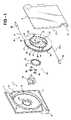
- a fiber optic protective carrier constructed in accordance with the inventioncomprises two container halves 1 and 2 which, when fused or welded to one another, form a hollow casing or container having a front wall 3 and a rear wall 4 .
- the casing half 1has a marginal flange 5 and the casing half 2 has a similar flange 6 engageable with one another when the halves are placed in confronting relation so as to be welded or otherwise secured to one another to form the hollow casing.
- the casing half 1is formed with two diagonally spaced inlet portions 7 and 8
- the casing half 2is provided with similar inlet portions 9 and 10 which, when the casing halves are secured to one another, form inwardly tapering passages through the casing.
- the casing half 1has an opening 11 therein for the accommodation of a cylindrical, rotatable crank body 12 having at one side a crank arm 13 and at the opposite side three circumferentially spaced spindles 14 .
- the casing half 1also has a cylindrical cavity 15 therein in which is accommodated a substantially cylindrical rotor 16 having a cylindrical recess 17 in one face thereof. At the center of the recess is a hub 18 which accommodates a stub 19 fixed on the inner face of the back wall 4 of the casing half 2 so as to mount the rotor 16 for rotation about the axis formed by the hub.
- the guide 19Accommodated in the recess 17 is an S-shaped guide 19 for a fiber optic cable 20 .
- the guidecomprises a pair of spaced apart, parallel walls 21 secured to the base of the cavity 17 .
- the walls 21together define a curvilinear guide channel 22 open at both ends.
- the curvatures of the channel 22have radii preferably greater than the minimum required to cause attenuation of the signal carried by the cable.
- the hub 18spans the channel 22 , but does not obstruct the latter.
- the base of the cavityforms a bottom for the channel.
- Transmission means 34is provided for effecting rotation of the rotor 16 in response to rotation of the crank body 12 .
- the transmission meanscomprises a ring gear 35 accommodated in an opening 36 in the front wall 3 of the casing half 1 .
- the wall of the opening and the periphery of the gearare provided with interengaging projections 37 and complementary grooves.
- the terminations 32 and 33are extended to a position in which they project beyond the edges of the casing, and then placed in the openings at the diagonally spaced corners of the casing.
- the casing partsthen are assembled and the two halves secured to one another so as to form an enclosure for the rotary parts of the assembly and the cable.
- the rotor 16may be rotated via the crank 13 in such direction as to cause the terminations 32 and 33 to be accommodated in the tapered openings.
Landscapes
- Physics & Mathematics (AREA)
- General Physics & Mathematics (AREA)
- Optics & Photonics (AREA)
- Light Guides In General And Applications Therefor (AREA)
- Details Of Connecting Devices For Male And Female Coupling (AREA)
- Electric Cable Arrangement Between Relatively Moving Parts (AREA)
Abstract
Description
Claims (11)
Priority Applications (2)
| Application Number | Priority Date | Filing Date | Title |
|---|---|---|---|
| US11/251,995US7116883B2 (en) | 2004-11-19 | 2005-10-17 | Fiber optic protective carrier |
| PCT/US2005/042040WO2006055865A2 (en) | 2004-11-19 | 2005-11-21 | Fiber optic protective carrier |
Applications Claiming Priority (2)
| Application Number | Priority Date | Filing Date | Title |
|---|---|---|---|
| US62954504P | 2004-11-19 | 2004-11-19 | |
| US11/251,995US7116883B2 (en) | 2004-11-19 | 2005-10-17 | Fiber optic protective carrier |
Publications (2)
| Publication Number | Publication Date |
|---|---|
| US20060110119A1 US20060110119A1 (en) | 2006-05-25 |
| US7116883B2true US7116883B2 (en) | 2006-10-03 |
Family
ID=36407816
Family Applications (1)
| Application Number | Title | Priority Date | Filing Date |
|---|---|---|---|
| US11/251,995Expired - LifetimeUS7116883B2 (en) | 2004-11-19 | 2005-10-17 | Fiber optic protective carrier |
Country Status (2)
| Country | Link |
|---|---|
| US (1) | US7116883B2 (en) |
| WO (1) | WO2006055865A2 (en) |
Cited By (55)
| Publication number | Priority date | Publication date | Assignee | Title |
|---|---|---|---|---|
| US20080118207A1 (en)* | 2005-01-24 | 2008-05-22 | Sumitomo Electric Industries, Ltd. | Optical Fiber Module |
| US20090317046A1 (en)* | 2008-04-21 | 2009-12-24 | Thomas Marcouiller | Cable anchoring device |
| US20100021122A1 (en)* | 2008-07-23 | 2010-01-28 | Hurley William C | Retractable module for patch cords |
| US20100054683A1 (en)* | 2008-08-29 | 2010-03-04 | Cooke Terry L | Rear-Installable Fiber Optic Modules and Equipment |
| US20100296790A1 (en)* | 2009-05-21 | 2010-11-25 | Cooke Terry L | Fiber Optic Equipment Supporting Moveable Fiber Optic Equipment Tray(s) and Module(s), and Related Equipment and Methods |
| US20110024543A1 (en)* | 2009-07-30 | 2011-02-03 | Mark Smrha | Spool for telecommunications cable and method |
| US8238707B2 (en) | 2009-07-30 | 2012-08-07 | Adc Telecommunications, Inc. | Locking spool for telecommunications cable and method |
| US8248776B2 (en) | 2010-08-19 | 2012-08-21 | Xyratex Technology Limited | Method and apparatus for storage of cables |
| US8270152B2 (en) | 2010-08-19 | 2012-09-18 | Xyratex Technology Limited | Method and apparatus for storage of cables |
| US8433171B2 (en) | 2009-06-19 | 2013-04-30 | Corning Cable Systems Llc | High fiber optic cable packing density apparatus |
| US8452148B2 (en) | 2008-08-29 | 2013-05-28 | Corning Cable Systems Llc | Independently translatable modules and fiber optic equipment trays in fiber optic equipment |
| US8542973B2 (en) | 2010-04-23 | 2013-09-24 | Ccs Technology, Inc. | Fiber optic distribution device |
| US8593828B2 (en) | 2010-02-04 | 2013-11-26 | Corning Cable Systems Llc | Communications equipment housings, assemblies, and related alignment features and methods |
| US8625950B2 (en) | 2009-12-18 | 2014-01-07 | Corning Cable Systems Llc | Rotary locking apparatus for fiber optic equipment trays and related methods |
| US8660397B2 (en) | 2010-04-30 | 2014-02-25 | Corning Cable Systems Llc | Multi-layer module |
| US8662760B2 (en) | 2010-10-29 | 2014-03-04 | Corning Cable Systems Llc | Fiber optic connector employing optical fiber guide member |
| US8699838B2 (en) | 2009-05-14 | 2014-04-15 | Ccs Technology, Inc. | Fiber optic furcation module |
| US8705926B2 (en) | 2010-04-30 | 2014-04-22 | Corning Optical Communications LLC | Fiber optic housings having a removable top, and related components and methods |
| US8712206B2 (en) | 2009-06-19 | 2014-04-29 | Corning Cable Systems Llc | High-density fiber optic modules and module housings and related equipment |
| US8718436B2 (en) | 2010-08-30 | 2014-05-06 | Corning Cable Systems Llc | Methods, apparatuses for providing secure fiber optic connections |
| US8720810B2 (en) | 2011-02-11 | 2014-05-13 | Adc Telecommunications, Inc. | Spool for telecommunications cable and method |
| US8879881B2 (en) | 2010-04-30 | 2014-11-04 | Corning Cable Systems Llc | Rotatable routing guide and assembly |
| US8913866B2 (en) | 2010-03-26 | 2014-12-16 | Corning Cable Systems Llc | Movable adapter panel |
| US8953924B2 (en) | 2011-09-02 | 2015-02-10 | Corning Cable Systems Llc | Removable strain relief brackets for securing fiber optic cables and/or optical fibers to fiber optic equipment, and related assemblies and methods |
| US8985862B2 (en) | 2013-02-28 | 2015-03-24 | Corning Cable Systems Llc | High-density multi-fiber adapter housings |
| US8989547B2 (en) | 2011-06-30 | 2015-03-24 | Corning Cable Systems Llc | Fiber optic equipment assemblies employing non-U-width-sized housings and related methods |
| US8995812B2 (en) | 2012-10-26 | 2015-03-31 | Ccs Technology, Inc. | Fiber optic management unit and fiber optic distribution device |
| US9008485B2 (en) | 2011-05-09 | 2015-04-14 | Corning Cable Systems Llc | Attachment mechanisms employed to attach a rear housing section to a fiber optic housing, and related assemblies and methods |
| US9020320B2 (en) | 2008-08-29 | 2015-04-28 | Corning Cable Systems Llc | High density and bandwidth fiber optic apparatuses and related equipment and methods |
| US9022814B2 (en) | 2010-04-16 | 2015-05-05 | Ccs Technology, Inc. | Sealing and strain relief device for data cables |
| US9038832B2 (en) | 2011-11-30 | 2015-05-26 | Corning Cable Systems Llc | Adapter panel support assembly |
| US9042702B2 (en) | 2012-09-18 | 2015-05-26 | Corning Cable Systems Llc | Platforms and systems for fiber optic cable attachment |
| US9059578B2 (en) | 2009-02-24 | 2015-06-16 | Ccs Technology, Inc. | Holding device for a cable or an assembly for use with a cable |
| US9075217B2 (en) | 2010-04-30 | 2015-07-07 | Corning Cable Systems Llc | Apparatuses and related components and methods for expanding capacity of fiber optic housings |
| US9075216B2 (en) | 2009-05-21 | 2015-07-07 | Corning Cable Systems Llc | Fiber optic housings configured to accommodate fiber optic modules/cassettes and fiber optic panels, and related components and methods |
| US9116324B2 (en) | 2010-10-29 | 2015-08-25 | Corning Cable Systems Llc | Stacked fiber optic modules and fiber optic equipment configured to support stacked fiber optic modules |
| US9126802B2 (en) | 2012-04-30 | 2015-09-08 | Adc Telecommunications, Inc. | Payout spool with automatic cable disconnect/reconnect |
| US9213161B2 (en) | 2010-11-05 | 2015-12-15 | Corning Cable Systems Llc | Fiber body holder and strain relief device |
| US9250409B2 (en) | 2012-07-02 | 2016-02-02 | Corning Cable Systems Llc | Fiber-optic-module trays and drawers for fiber-optic equipment |
| US9279951B2 (en) | 2010-10-27 | 2016-03-08 | Corning Cable Systems Llc | Fiber optic module for limited space applications having a partially sealed module sub-assembly |
| US9500831B2 (en) | 2012-04-30 | 2016-11-22 | Commscope Technologies Llc | Cable payout cassette with single layer cable storage area |
| US9519118B2 (en) | 2010-04-30 | 2016-12-13 | Corning Optical Communications LLC | Removable fiber management sections for fiber optic housings, and related components and methods |
| US9528289B2 (en)* | 2014-08-15 | 2016-12-27 | Hubbell Incorporated | Apparatus for supporting cable |
| US9581783B2 (en) | 2013-09-18 | 2017-02-28 | Hubbell Incorporated | Fiber cable and drop wire organizer |
| US9632270B2 (en) | 2010-04-30 | 2017-04-25 | Corning Optical Communications LLC | Fiber optic housings configured for tool-less assembly, and related components and methods |
| US9645344B2 (en) | 2015-08-11 | 2017-05-09 | Hubbell Incorporated | Inverted cable storage device |
| US9645317B2 (en) | 2011-02-02 | 2017-05-09 | Corning Optical Communications LLC | Optical backplane extension modules, and related assemblies suitable for establishing optical connections to information processing modules disposed in equipment racks |
| US9709767B2 (en)* | 2013-11-13 | 2017-07-18 | Oplink Communications, Llc | Optical fiber ribbon retractor |
| US9722407B2 (en) | 2012-04-30 | 2017-08-01 | Commscope Technologies Llc | Guided cable storage assembly with switchbacks |
| US9720195B2 (en) | 2010-04-30 | 2017-08-01 | Corning Optical Communications LLC | Apparatuses and related components and methods for attachment and release of fiber optic housings to and from an equipment rack |
| US9825706B2 (en) | 2014-02-28 | 2017-11-21 | United Technologies Corporation | Support system for fiber optic components in harsh environment machines |
| US9908742B2 (en) | 2012-04-30 | 2018-03-06 | Commscope Technologies Llc | Cable storage spool with center feed |
| US10437001B1 (en)* | 2018-09-20 | 2019-10-08 | The United States Of America As Represented By The Secretary Of The Navy | Fiber optic drogue and cable retraction spool |
| US11240925B1 (en)* | 2020-10-20 | 2022-02-01 | Dell Products L.P. | System and method for long cable management and plug protection system |
| US11294135B2 (en) | 2008-08-29 | 2022-04-05 | Corning Optical Communications LLC | High density and bandwidth fiber optic apparatuses and related equipment and methods |
Families Citing this family (8)
| Publication number | Priority date | Publication date | Assignee | Title |
|---|---|---|---|---|
| DE102008022666A1 (en) | 2008-05-07 | 2009-12-03 | Endox Feinwerktechnik Gmbh | Wire dispenser for receiving an elastically deformable wire |
| KR101029008B1 (en) | 2011-01-28 | 2011-04-14 | 이민석 | Self-winding reel jumper cords for optical cables |
| US8737796B2 (en)* | 2011-05-20 | 2014-05-27 | Adc Telecommunications, Inc. | Rapid universal rack mount enclosure |
| US10390589B2 (en) | 2016-03-15 | 2019-08-27 | Nike, Inc. | Drive mechanism for automated footwear platform |
| CN110342414B (en)* | 2019-08-12 | 2023-12-15 | 重庆宇爵智能科技有限公司 | Winding lifting device |
| US11428604B2 (en)* | 2019-12-06 | 2022-08-30 | Christine Pons | Compact optical time domain reflectometer with integrated time delay fiber waveguide |
| CN113023504B (en)* | 2021-03-16 | 2023-06-23 | 国网新疆电力有限公司哈密供电公司 | Multifunctional relay protection tester trolley case |
| KR102362608B1 (en)* | 2021-09-09 | 2022-02-15 | (주)바이컴 | Device of forming winding pattern of DTS optical cable |
Citations (10)
| Publication number | Priority date | Publication date | Assignee | Title |
|---|---|---|---|---|
| US6349893B1 (en)* | 2000-02-01 | 2002-02-26 | Avaya Technology Corp. | Retractable fiber slack storage device |
| US20020118944A1 (en)* | 2001-02-28 | 2002-08-29 | Corning Cable Systems Llc | Optical fiber storage reel |
| US6484958B1 (en)* | 2001-11-20 | 2002-11-26 | Dowslake Microsystems Corporation | Patch cord caddy |
| US6533206B2 (en)* | 2000-06-06 | 2003-03-18 | Toyokuni Electric Cable Co., Ltd. | Device for winding remaining line of optical fiber cable |
| US20030095773A1 (en)* | 2001-11-20 | 2003-05-22 | Toyokuni Electric Cable Co., Ltd. | Device for winding optical fiber cable |
| US6580866B2 (en)* | 2001-05-16 | 2003-06-17 | Lucent Technologies Inc. | Fiber splice holder with protected slack storage feature |
| US6915058B2 (en)* | 2003-02-28 | 2005-07-05 | Corning Cable Systems Llc | Retractable optical fiber assembly |
| US7000863B2 (en)* | 2003-09-29 | 2006-02-21 | Lucent Technologies Inc. | Method and apparatus for operational low-stress optical fiber storage |
| US20060045458A1 (en)* | 2004-08-26 | 2006-03-02 | Koji Sasaki | Holder and structure for organizing excess length |
| US20060093307A1 (en)* | 2004-10-29 | 2006-05-04 | Thomas Lowentat | Unit for synchronous extension and retraction of two wire segments, and a motor vehicle having such a unit |
- 2005
- 2005-10-17USUS11/251,995patent/US7116883B2/ennot_activeExpired - Lifetime
- 2005-11-21WOPCT/US2005/042040patent/WO2006055865A2/enactiveApplication Filing
Patent Citations (11)
| Publication number | Priority date | Publication date | Assignee | Title |
|---|---|---|---|---|
| US6349893B1 (en)* | 2000-02-01 | 2002-02-26 | Avaya Technology Corp. | Retractable fiber slack storage device |
| US6533206B2 (en)* | 2000-06-06 | 2003-03-18 | Toyokuni Electric Cable Co., Ltd. | Device for winding remaining line of optical fiber cable |
| US20020118944A1 (en)* | 2001-02-28 | 2002-08-29 | Corning Cable Systems Llc | Optical fiber storage reel |
| US6580866B2 (en)* | 2001-05-16 | 2003-06-17 | Lucent Technologies Inc. | Fiber splice holder with protected slack storage feature |
| US6484958B1 (en)* | 2001-11-20 | 2002-11-26 | Dowslake Microsystems Corporation | Patch cord caddy |
| US20030095773A1 (en)* | 2001-11-20 | 2003-05-22 | Toyokuni Electric Cable Co., Ltd. | Device for winding optical fiber cable |
| US6915058B2 (en)* | 2003-02-28 | 2005-07-05 | Corning Cable Systems Llc | Retractable optical fiber assembly |
| US20050226588A1 (en)* | 2003-02-28 | 2005-10-13 | Pons Sean M | Retractable optical fiber assembly |
| US7000863B2 (en)* | 2003-09-29 | 2006-02-21 | Lucent Technologies Inc. | Method and apparatus for operational low-stress optical fiber storage |
| US20060045458A1 (en)* | 2004-08-26 | 2006-03-02 | Koji Sasaki | Holder and structure for organizing excess length |
| US20060093307A1 (en)* | 2004-10-29 | 2006-05-04 | Thomas Lowentat | Unit for synchronous extension and retraction of two wire segments, and a motor vehicle having such a unit |
Cited By (84)
| Publication number | Priority date | Publication date | Assignee | Title |
|---|---|---|---|---|
| US20080118207A1 (en)* | 2005-01-24 | 2008-05-22 | Sumitomo Electric Industries, Ltd. | Optical Fiber Module |
| US8090234B2 (en)* | 2008-04-21 | 2012-01-03 | Adc Telecommunications, Inc. | Cable anchoring device |
| US20090317046A1 (en)* | 2008-04-21 | 2009-12-24 | Thomas Marcouiller | Cable anchoring device |
| US20100021122A1 (en)* | 2008-07-23 | 2010-01-28 | Hurley William C | Retractable module for patch cords |
| US7680386B2 (en)* | 2008-07-23 | 2010-03-16 | Corning Cable Systems Llc | Retractable module for patch cords |
| US10459184B2 (en) | 2008-08-29 | 2019-10-29 | Corning Optical Communications LLC | High density and bandwidth fiber optic apparatuses and related equipment and methods |
| US20100054683A1 (en)* | 2008-08-29 | 2010-03-04 | Cooke Terry L | Rear-Installable Fiber Optic Modules and Equipment |
| US9910236B2 (en) | 2008-08-29 | 2018-03-06 | Corning Optical Communications LLC | High density and bandwidth fiber optic apparatuses and related equipment and methods |
| US8184938B2 (en) | 2008-08-29 | 2012-05-22 | Corning Cable Systems Llc | Rear-installable fiber optic modules and equipment |
| US10094996B2 (en) | 2008-08-29 | 2018-10-09 | Corning Optical Communications, Llc | Independently translatable modules and fiber optic equipment trays in fiber optic equipment |
| US12072545B2 (en) | 2008-08-29 | 2024-08-27 | Corning Optical Communications LLC | High density and bandwidth fiber optic apparatuses and related equipment and methods |
| US11754796B2 (en) | 2008-08-29 | 2023-09-12 | Corning Optical Communications LLC | Independently translatable modules and fiber optic equipment trays in fiber optic equipment |
| US9020320B2 (en) | 2008-08-29 | 2015-04-28 | Corning Cable Systems Llc | High density and bandwidth fiber optic apparatuses and related equipment and methods |
| US10120153B2 (en) | 2008-08-29 | 2018-11-06 | Corning Optical Communications, Llc | Independently translatable modules and fiber optic equipment trays in fiber optic equipment |
| US8452148B2 (en) | 2008-08-29 | 2013-05-28 | Corning Cable Systems Llc | Independently translatable modules and fiber optic equipment trays in fiber optic equipment |
| US10126514B2 (en) | 2008-08-29 | 2018-11-13 | Corning Optical Communications, Llc | Independently translatable modules and fiber optic equipment trays in fiber optic equipment |
| US10564378B2 (en) | 2008-08-29 | 2020-02-18 | Corning Optical Communications LLC | High density and bandwidth fiber optic apparatuses and related equipment and methods |
| US10606014B2 (en) | 2008-08-29 | 2020-03-31 | Corning Optical Communications LLC | Independently translatable modules and fiber optic equipment trays in fiber optic equipment |
| US10222570B2 (en) | 2008-08-29 | 2019-03-05 | Corning Optical Communications LLC | Independently translatable modules and fiber optic equipment trays in fiber optic equipment |
| US10852499B2 (en) | 2008-08-29 | 2020-12-01 | Corning Optical Communications LLC | High density and bandwidth fiber optic apparatuses and related equipment and methods |
| US10444456B2 (en) | 2008-08-29 | 2019-10-15 | Corning Optical Communications LLC | High density and bandwidth fiber optic apparatuses and related equipment and methods |
| US11609396B2 (en) | 2008-08-29 | 2023-03-21 | Corning Optical Communications LLC | High density and bandwidth fiber optic apparatuses and related equipment and methods |
| US10422971B2 (en) | 2008-08-29 | 2019-09-24 | Corning Optical Communicatinos LLC | High density and bandwidth fiber optic apparatuses and related equipment and methods |
| US11294136B2 (en) | 2008-08-29 | 2022-04-05 | Corning Optical Communications LLC | High density and bandwidth fiber optic apparatuses and related equipment and methods |
| US10416405B2 (en) | 2008-08-29 | 2019-09-17 | Corning Optical Communications LLC | Independently translatable modules and fiber optic equipment trays in fiber optic equipment |
| US11294135B2 (en) | 2008-08-29 | 2022-04-05 | Corning Optical Communications LLC | High density and bandwidth fiber optic apparatuses and related equipment and methods |
| US11092767B2 (en) | 2008-08-29 | 2021-08-17 | Corning Optical Communications LLC | High density and bandwidth fiber optic apparatuses and related equipment and methods |
| US11086089B2 (en) | 2008-08-29 | 2021-08-10 | Corning Optical Communications LLC | High density and bandwidth fiber optic apparatuses and related equipment and methods |
| US9059578B2 (en) | 2009-02-24 | 2015-06-16 | Ccs Technology, Inc. | Holding device for a cable or an assembly for use with a cable |
| US8699838B2 (en) | 2009-05-14 | 2014-04-15 | Ccs Technology, Inc. | Fiber optic furcation module |
| US9075216B2 (en) | 2009-05-21 | 2015-07-07 | Corning Cable Systems Llc | Fiber optic housings configured to accommodate fiber optic modules/cassettes and fiber optic panels, and related components and methods |
| US8538226B2 (en) | 2009-05-21 | 2013-09-17 | Corning Cable Systems Llc | Fiber optic equipment guides and rails configured with stopping position(s), and related equipment and methods |
| US8280216B2 (en) | 2009-05-21 | 2012-10-02 | Corning Cable Systems Llc | Fiber optic equipment supporting moveable fiber optic equipment tray(s) and module(s), and related equipment and methods |
| US20100296790A1 (en)* | 2009-05-21 | 2010-11-25 | Cooke Terry L | Fiber Optic Equipment Supporting Moveable Fiber Optic Equipment Tray(s) and Module(s), and Related Equipment and Methods |
| US8712206B2 (en) | 2009-06-19 | 2014-04-29 | Corning Cable Systems Llc | High-density fiber optic modules and module housings and related equipment |
| US8433171B2 (en) | 2009-06-19 | 2013-04-30 | Corning Cable Systems Llc | High fiber optic cable packing density apparatus |
| US20110024543A1 (en)* | 2009-07-30 | 2011-02-03 | Mark Smrha | Spool for telecommunications cable and method |
| US8474742B2 (en) | 2009-07-30 | 2013-07-02 | Adc Telecommunications, Inc. | Spool for telecommunications cable and method |
| US8238707B2 (en) | 2009-07-30 | 2012-08-07 | Adc Telecommunications, Inc. | Locking spool for telecommunications cable and method |
| US8625950B2 (en) | 2009-12-18 | 2014-01-07 | Corning Cable Systems Llc | Rotary locking apparatus for fiber optic equipment trays and related methods |
| US8992099B2 (en) | 2010-02-04 | 2015-03-31 | Corning Cable Systems Llc | Optical interface cards, assemblies, and related methods, suited for installation and use in antenna system equipment |
| US8593828B2 (en) | 2010-02-04 | 2013-11-26 | Corning Cable Systems Llc | Communications equipment housings, assemblies, and related alignment features and methods |
| US8913866B2 (en) | 2010-03-26 | 2014-12-16 | Corning Cable Systems Llc | Movable adapter panel |
| US9022814B2 (en) | 2010-04-16 | 2015-05-05 | Ccs Technology, Inc. | Sealing and strain relief device for data cables |
| US8542973B2 (en) | 2010-04-23 | 2013-09-24 | Ccs Technology, Inc. | Fiber optic distribution device |
| US8660397B2 (en) | 2010-04-30 | 2014-02-25 | Corning Cable Systems Llc | Multi-layer module |
| US8705926B2 (en) | 2010-04-30 | 2014-04-22 | Corning Optical Communications LLC | Fiber optic housings having a removable top, and related components and methods |
| US8879881B2 (en) | 2010-04-30 | 2014-11-04 | Corning Cable Systems Llc | Rotatable routing guide and assembly |
| US9519118B2 (en) | 2010-04-30 | 2016-12-13 | Corning Optical Communications LLC | Removable fiber management sections for fiber optic housings, and related components and methods |
| US9720195B2 (en) | 2010-04-30 | 2017-08-01 | Corning Optical Communications LLC | Apparatuses and related components and methods for attachment and release of fiber optic housings to and from an equipment rack |
| US9075217B2 (en) | 2010-04-30 | 2015-07-07 | Corning Cable Systems Llc | Apparatuses and related components and methods for expanding capacity of fiber optic housings |
| US9632270B2 (en) | 2010-04-30 | 2017-04-25 | Corning Optical Communications LLC | Fiber optic housings configured for tool-less assembly, and related components and methods |
| US8270152B2 (en) | 2010-08-19 | 2012-09-18 | Xyratex Technology Limited | Method and apparatus for storage of cables |
| US8248776B2 (en) | 2010-08-19 | 2012-08-21 | Xyratex Technology Limited | Method and apparatus for storage of cables |
| US8718436B2 (en) | 2010-08-30 | 2014-05-06 | Corning Cable Systems Llc | Methods, apparatuses for providing secure fiber optic connections |
| US9279951B2 (en) | 2010-10-27 | 2016-03-08 | Corning Cable Systems Llc | Fiber optic module for limited space applications having a partially sealed module sub-assembly |
| US8662760B2 (en) | 2010-10-29 | 2014-03-04 | Corning Cable Systems Llc | Fiber optic connector employing optical fiber guide member |
| US9116324B2 (en) | 2010-10-29 | 2015-08-25 | Corning Cable Systems Llc | Stacked fiber optic modules and fiber optic equipment configured to support stacked fiber optic modules |
| US9213161B2 (en) | 2010-11-05 | 2015-12-15 | Corning Cable Systems Llc | Fiber body holder and strain relief device |
| US9645317B2 (en) | 2011-02-02 | 2017-05-09 | Corning Optical Communications LLC | Optical backplane extension modules, and related assemblies suitable for establishing optical connections to information processing modules disposed in equipment racks |
| US10481335B2 (en) | 2011-02-02 | 2019-11-19 | Corning Optical Communications, Llc | Dense shuttered fiber optic connectors and assemblies suitable for establishing optical connections for optical backplanes in equipment racks |
| US8720810B2 (en) | 2011-02-11 | 2014-05-13 | Adc Telecommunications, Inc. | Spool for telecommunications cable and method |
| US9008485B2 (en) | 2011-05-09 | 2015-04-14 | Corning Cable Systems Llc | Attachment mechanisms employed to attach a rear housing section to a fiber optic housing, and related assemblies and methods |
| US8989547B2 (en) | 2011-06-30 | 2015-03-24 | Corning Cable Systems Llc | Fiber optic equipment assemblies employing non-U-width-sized housings and related methods |
| US8953924B2 (en) | 2011-09-02 | 2015-02-10 | Corning Cable Systems Llc | Removable strain relief brackets for securing fiber optic cables and/or optical fibers to fiber optic equipment, and related assemblies and methods |
| US9038832B2 (en) | 2011-11-30 | 2015-05-26 | Corning Cable Systems Llc | Adapter panel support assembly |
| US9126802B2 (en) | 2012-04-30 | 2015-09-08 | Adc Telecommunications, Inc. | Payout spool with automatic cable disconnect/reconnect |
| US9939600B2 (en) | 2012-04-30 | 2018-04-10 | Commscope Technologies Llc | Optical fiber disconnect/reconnect apparatus |
| US9908742B2 (en) | 2012-04-30 | 2018-03-06 | Commscope Technologies Llc | Cable storage spool with center feed |
| US9722407B2 (en) | 2012-04-30 | 2017-08-01 | Commscope Technologies Llc | Guided cable storage assembly with switchbacks |
| US9500831B2 (en) | 2012-04-30 | 2016-11-22 | Commscope Technologies Llc | Cable payout cassette with single layer cable storage area |
| US10625978B2 (en) | 2012-04-30 | 2020-04-21 | Commscope Technologies Llc | Cable storage spool with center feed |
| US9250409B2 (en) | 2012-07-02 | 2016-02-02 | Corning Cable Systems Llc | Fiber-optic-module trays and drawers for fiber-optic equipment |
| US9042702B2 (en) | 2012-09-18 | 2015-05-26 | Corning Cable Systems Llc | Platforms and systems for fiber optic cable attachment |
| US8995812B2 (en) | 2012-10-26 | 2015-03-31 | Ccs Technology, Inc. | Fiber optic management unit and fiber optic distribution device |
| US8985862B2 (en) | 2013-02-28 | 2015-03-24 | Corning Cable Systems Llc | High-density multi-fiber adapter housings |
| US9581783B2 (en) | 2013-09-18 | 2017-02-28 | Hubbell Incorporated | Fiber cable and drop wire organizer |
| US9709767B2 (en)* | 2013-11-13 | 2017-07-18 | Oplink Communications, Llc | Optical fiber ribbon retractor |
| US9825706B2 (en) | 2014-02-28 | 2017-11-21 | United Technologies Corporation | Support system for fiber optic components in harsh environment machines |
| US10215946B2 (en) | 2014-08-15 | 2019-02-26 | Hubbell Incorporated | Apparatus for supporting cable |
| US9528289B2 (en)* | 2014-08-15 | 2016-12-27 | Hubbell Incorporated | Apparatus for supporting cable |
| US9645344B2 (en) | 2015-08-11 | 2017-05-09 | Hubbell Incorporated | Inverted cable storage device |
| US10437001B1 (en)* | 2018-09-20 | 2019-10-08 | The United States Of America As Represented By The Secretary Of The Navy | Fiber optic drogue and cable retraction spool |
| US11240925B1 (en)* | 2020-10-20 | 2022-02-01 | Dell Products L.P. | System and method for long cable management and plug protection system |
Also Published As
| Publication number | Publication date |
|---|---|
| WO2006055865A3 (en) | 2006-08-31 |
| US20060110119A1 (en) | 2006-05-25 |
| WO2006055865A2 (en) | 2006-05-26 |
Similar Documents
| Publication | Publication Date | Title |
|---|---|---|
| US7116883B2 (en) | Fiber optic protective carrier | |
| US7266283B2 (en) | Fiber optic storing and dispensing apparatus | |
| CA2617944C (en) | Fiber optic cable protective apparatus | |
| JP2593851B2 (en) | Apparatus for storing extra length light guides | |
| JP2904836B2 (en) | Splice tray | |
| RU1835081C (en) | Film cassette | |
| EP0951748B1 (en) | Retractable reel with channeled ratchet mechanism | |
| US5252085A (en) | Clock spring connector | |
| JPH0213577A (en) | Winding-delivering device for optical fiber cable | |
| JP2002544093A (en) | Rewind cord device | |
| KR101896608B1 (en) | Earphone having wire retractable device | |
| US11231557B2 (en) | Cable spool re-orientation device for a wall box | |
| JPS5851201B2 (en) | Spiral tape measuring device | |
| WO2017140725A1 (en) | Spool with multi-position loop keeper | |
| US20020118944A1 (en) | Optical fiber storage reel | |
| US6065709A (en) | Cable storage reel | |
| CA3021203C (en) | Retractable fiber optic reel assembly | |
| US3780964A (en) | Dispenser housing for wire and the like | |
| WO2000044661A1 (en) | Box-like dispenser with a supporting device for a reel with a wound-on electrical cord or similar rope-like element, which can be unreeled from the dispenser | |
| WO1996019745A2 (en) | Magazine and cassette for storage of optical fibres | |
| WO1988000918A1 (en) | Anti-clockspringing apparatus and method | |
| US20050242223A1 (en) | Manually loaded cord reeling device | |
| JP2008197530A (en) | Optical fiber winding device | |
| JP3009437B2 (en) | Apparatus for accommodating extra length optical leads | |
| EP0782539B1 (en) | Winding reel for wire, cable, etc. |
Legal Events
| Date | Code | Title | Description |
|---|---|---|---|
| AS | Assignment | Owner name:FIBER OPTIC PROTECTION SYSTEMS, INC., MICHIGAN Free format text:ASSIGNMENT OF ASSIGNORS INTEREST;ASSIGNORS:KLINE, JAMES R.;KLINE, THOMAS J.;SENE, DUSTIN S.;REEL/FRAME:017111/0600 Effective date:20051003 | |
| FEPP | Fee payment procedure | Free format text:PAYOR NUMBER ASSIGNED (ORIGINAL EVENT CODE: ASPN); ENTITY STATUS OF PATENT OWNER: MICROENTITY | |
| STCF | Information on status: patent grant | Free format text:PATENTED CASE | |
| FPAY | Fee payment | Year of fee payment:4 | |
| FEPP | Fee payment procedure | Free format text:PAYER NUMBER DE-ASSIGNED (ORIGINAL EVENT CODE: RMPN); ENTITY STATUS OF PATENT OWNER: MICROENTITY Free format text:PAYOR NUMBER ASSIGNED (ORIGINAL EVENT CODE: ASPN); ENTITY STATUS OF PATENT OWNER: MICROENTITY | |
| FEPP | Fee payment procedure | Free format text:PATENT HOLDER CLAIMS MICRO ENTITY STATUS, ENTITY STATUS SET TO MICRO (ORIGINAL EVENT CODE: STOM); ENTITY STATUS OF PATENT OWNER: MICROENTITY | |
| FPAY | Fee payment | Year of fee payment:8 | |
| MAFP | Maintenance fee payment | Free format text:PAYMENT OF MAINTENANCE FEE, 12TH YEAR, MICRO ENTITY (ORIGINAL EVENT CODE: M3553) Year of fee payment:12 |