US7116714B2 - Video coding - Google Patents
Video codingDownload PDFInfo
- Publication number
- US7116714B2 US7116714B2US09/924,582US92458201AUS7116714B2US 7116714 B2US7116714 B2US 7116714B2US 92458201 AUS92458201 AUS 92458201AUS 7116714 B2US7116714 B2US 7116714B2
- Authority
- US
- United States
- Prior art keywords
- picture
- encoded
- sequence
- video
- representation
- Prior art date
- Legal status (The legal status is an assumption and is not a legal conclusion. Google has not performed a legal analysis and makes no representation as to the accuracy of the status listed.)
- Expired - Lifetime, expires
Links
- 238000000034methodMethods0.000claimsabstractdescription34
- 230000000737periodic effectEffects0.000claimsdescription8
- 238000012545processingMethods0.000claimsdescription5
- 238000012544monitoring processMethods0.000claimsdescription2
- 230000011664signalingEffects0.000claims1
- 230000005540biological transmissionEffects0.000description16
- 230000006835compressionEffects0.000description11
- 238000007906compressionMethods0.000description11
- 230000002123temporal effectEffects0.000description11
- 230000008569processEffects0.000description5
- 239000000872bufferSubstances0.000description4
- 230000003139buffering effectEffects0.000description4
- 238000010586diagramMethods0.000description4
- 230000004044responseEffects0.000description4
- 238000004891communicationMethods0.000description3
- 238000012937correctionMethods0.000description3
- 238000010295mobile communicationMethods0.000description3
- 239000013598vectorSubstances0.000description3
- 230000009286beneficial effectEffects0.000description2
- 230000015556catabolic processEffects0.000description2
- 238000006731degradation reactionMethods0.000description2
- 230000000694effectsEffects0.000description2
- 230000009467reductionEffects0.000description2
- 230000003595spectral effectEffects0.000description2
- 230000009471actionEffects0.000description1
- 230000008901benefitEffects0.000description1
- 230000008859changeEffects0.000description1
- 230000001934delayEffects0.000description1
- 238000001514detection methodMethods0.000description1
- 230000003116impacting effectEffects0.000description1
- 230000003993interactionEffects0.000description1
- 239000000463materialSubstances0.000description1
- 238000012986modificationMethods0.000description1
- 230000004048modificationEffects0.000description1
- 230000000644propagated effectEffects0.000description1
- 238000011084recoveryMethods0.000description1
- 238000013468resource allocationMethods0.000description1
- 230000009466transformationEffects0.000description1
- 230000001131transforming effectEffects0.000description1
- 230000000007visual effectEffects0.000description1
Images


Classifications
- H—ELECTRICITY
- H04—ELECTRIC COMMUNICATION TECHNIQUE
- H04N—PICTORIAL COMMUNICATION, e.g. TELEVISION
- H04N19/00—Methods or arrangements for coding, decoding, compressing or decompressing digital video signals
- H04N19/10—Methods or arrangements for coding, decoding, compressing or decompressing digital video signals using adaptive coding
- H04N19/102—Methods or arrangements for coding, decoding, compressing or decompressing digital video signals using adaptive coding characterised by the element, parameter or selection affected or controlled by the adaptive coding
- H04N19/103—Selection of coding mode or of prediction mode
- H04N19/105—Selection of the reference unit for prediction within a chosen coding or prediction mode, e.g. adaptive choice of position and number of pixels used for prediction
- H—ELECTRICITY
- H04—ELECTRIC COMMUNICATION TECHNIQUE
- H04N—PICTORIAL COMMUNICATION, e.g. TELEVISION
- H04N19/00—Methods or arrangements for coding, decoding, compressing or decompressing digital video signals
- H04N19/50—Methods or arrangements for coding, decoding, compressing or decompressing digital video signals using predictive coding
- H04N19/503—Methods or arrangements for coding, decoding, compressing or decompressing digital video signals using predictive coding involving temporal prediction
- H04N19/51—Motion estimation or motion compensation
- H04N19/573—Motion compensation with multiple frame prediction using two or more reference frames in a given prediction direction
- H—ELECTRICITY
- H04—ELECTRIC COMMUNICATION TECHNIQUE
- H04N—PICTORIAL COMMUNICATION, e.g. TELEVISION
- H04N19/00—Methods or arrangements for coding, decoding, compressing or decompressing digital video signals
- H04N19/10—Methods or arrangements for coding, decoding, compressing or decompressing digital video signals using adaptive coding
- H04N19/102—Methods or arrangements for coding, decoding, compressing or decompressing digital video signals using adaptive coding characterised by the element, parameter or selection affected or controlled by the adaptive coding
- H04N19/103—Selection of coding mode or of prediction mode
- H04N19/107—Selection of coding mode or of prediction mode between spatial and temporal predictive coding, e.g. picture refresh
- H—ELECTRICITY
- H04—ELECTRIC COMMUNICATION TECHNIQUE
- H04N—PICTORIAL COMMUNICATION, e.g. TELEVISION
- H04N19/00—Methods or arrangements for coding, decoding, compressing or decompressing digital video signals
- H04N19/10—Methods or arrangements for coding, decoding, compressing or decompressing digital video signals using adaptive coding
- H04N19/102—Methods or arrangements for coding, decoding, compressing or decompressing digital video signals using adaptive coding characterised by the element, parameter or selection affected or controlled by the adaptive coding
- H04N19/103—Selection of coding mode or of prediction mode
- H04N19/114—Adapting the group of pictures [GOP] structure, e.g. number of B-frames between two anchor frames
- H—ELECTRICITY
- H04—ELECTRIC COMMUNICATION TECHNIQUE
- H04N—PICTORIAL COMMUNICATION, e.g. TELEVISION
- H04N19/00—Methods or arrangements for coding, decoding, compressing or decompressing digital video signals
- H04N19/10—Methods or arrangements for coding, decoding, compressing or decompressing digital video signals using adaptive coding
- H04N19/134—Methods or arrangements for coding, decoding, compressing or decompressing digital video signals using adaptive coding characterised by the element, parameter or criterion affecting or controlling the adaptive coding
- H04N19/142—Detection of scene cut or scene change
- H—ELECTRICITY
- H04—ELECTRIC COMMUNICATION TECHNIQUE
- H04N—PICTORIAL COMMUNICATION, e.g. TELEVISION
- H04N19/00—Methods or arrangements for coding, decoding, compressing or decompressing digital video signals
- H04N19/10—Methods or arrangements for coding, decoding, compressing or decompressing digital video signals using adaptive coding
- H04N19/134—Methods or arrangements for coding, decoding, compressing or decompressing digital video signals using adaptive coding characterised by the element, parameter or criterion affecting or controlling the adaptive coding
- H04N19/164—Feedback from the receiver or from the transmission channel
- H04N19/166—Feedback from the receiver or from the transmission channel concerning the amount of transmission errors, e.g. bit error rate [BER]
- H—ELECTRICITY
- H04—ELECTRIC COMMUNICATION TECHNIQUE
- H04N—PICTORIAL COMMUNICATION, e.g. TELEVISION
- H04N19/00—Methods or arrangements for coding, decoding, compressing or decompressing digital video signals
- H04N19/10—Methods or arrangements for coding, decoding, compressing or decompressing digital video signals using adaptive coding
- H04N19/169—Methods or arrangements for coding, decoding, compressing or decompressing digital video signals using adaptive coding characterised by the coding unit, i.e. the structural portion or semantic portion of the video signal being the object or the subject of the adaptive coding
- H04N19/17—Methods or arrangements for coding, decoding, compressing or decompressing digital video signals using adaptive coding characterised by the coding unit, i.e. the structural portion or semantic portion of the video signal being the object or the subject of the adaptive coding the unit being an image region, e.g. an object
- H04N19/172—Methods or arrangements for coding, decoding, compressing or decompressing digital video signals using adaptive coding characterised by the coding unit, i.e. the structural portion or semantic portion of the video signal being the object or the subject of the adaptive coding the unit being an image region, e.g. an object the region being a picture, frame or field
- H—ELECTRICITY
- H04—ELECTRIC COMMUNICATION TECHNIQUE
- H04N—PICTORIAL COMMUNICATION, e.g. TELEVISION
- H04N19/00—Methods or arrangements for coding, decoding, compressing or decompressing digital video signals
- H04N19/10—Methods or arrangements for coding, decoding, compressing or decompressing digital video signals using adaptive coding
- H04N19/169—Methods or arrangements for coding, decoding, compressing or decompressing digital video signals using adaptive coding characterised by the coding unit, i.e. the structural portion or semantic portion of the video signal being the object or the subject of the adaptive coding
- H04N19/187—Methods or arrangements for coding, decoding, compressing or decompressing digital video signals using adaptive coding characterised by the coding unit, i.e. the structural portion or semantic portion of the video signal being the object or the subject of the adaptive coding the unit being a scalable video layer
- H—ELECTRICITY
- H04—ELECTRIC COMMUNICATION TECHNIQUE
- H04N—PICTORIAL COMMUNICATION, e.g. TELEVISION
- H04N19/00—Methods or arrangements for coding, decoding, compressing or decompressing digital video signals
- H04N19/30—Methods or arrangements for coding, decoding, compressing or decompressing digital video signals using hierarchical techniques, e.g. scalability
- H—ELECTRICITY
- H04—ELECTRIC COMMUNICATION TECHNIQUE
- H04N—PICTORIAL COMMUNICATION, e.g. TELEVISION
- H04N19/00—Methods or arrangements for coding, decoding, compressing or decompressing digital video signals
- H04N19/50—Methods or arrangements for coding, decoding, compressing or decompressing digital video signals using predictive coding
- H04N19/503—Methods or arrangements for coding, decoding, compressing or decompressing digital video signals using predictive coding involving temporal prediction
- H04N19/51—Motion estimation or motion compensation
- H—ELECTRICITY
- H04—ELECTRIC COMMUNICATION TECHNIQUE
- H04N—PICTORIAL COMMUNICATION, e.g. TELEVISION
- H04N19/00—Methods or arrangements for coding, decoding, compressing or decompressing digital video signals
- H04N19/60—Methods or arrangements for coding, decoding, compressing or decompressing digital video signals using transform coding
- H04N19/61—Methods or arrangements for coding, decoding, compressing or decompressing digital video signals using transform coding in combination with predictive coding
- H—ELECTRICITY
- H04—ELECTRIC COMMUNICATION TECHNIQUE
- H04N—PICTORIAL COMMUNICATION, e.g. TELEVISION
- H04N19/00—Methods or arrangements for coding, decoding, compressing or decompressing digital video signals
- H04N19/85—Methods or arrangements for coding, decoding, compressing or decompressing digital video signals using pre-processing or post-processing specially adapted for video compression
- H04N19/89—Methods or arrangements for coding, decoding, compressing or decompressing digital video signals using pre-processing or post-processing specially adapted for video compression involving methods or arrangements for detection of transmission errors at the decoder
- H04N19/895—Methods or arrangements for coding, decoding, compressing or decompressing digital video signals using pre-processing or post-processing specially adapted for video compression involving methods or arrangements for detection of transmission errors at the decoder in combination with error concealment
Definitions
- This inventionrelates to video coding.
- a video sequenceconsists of a series of still pictures or frames.
- Video compression methodsare based on reducing the redundant and perceptually irrelevant parts of video sequences.
- the redundancy in video sequencescan be categorised into spectral, spatial and temporal redundancy.
- Spectral redundancyrefers to the similarity between the different colour components of the same picture. Spatial redundancy results from the similarity between neighbouring pixels in a picture.
- Temporal redundancyexists because objects appearing in a previous image are also likely to appear in the current image. Compression can be achieved by taking advantage of this temporal redundancy and predicting the current picture from another picture, termed an anchor or reference picture. Further compression is achieved by generating motion compensation data that describes the motion between the current picture and the previous picture.
- Video compression methodstypically differentiate between pictures that utilise temporal redundancy reduction and those that do not.
- Compressed pictures that do not utilise temporal redundancy reduction methodsare usually called INTRA or I-frames or I-pictures.
- Temporally predicted imagesare usually forwardly predicted from a picture occurring before the current picture and are called INTER or P-frames or P-pictures.
- INTER or P-frames or P-picturesIn the INTER frame case, the predicted motion-compensated picture is rarely precise enough and therefore a spatially compressed prediction error frame is associated with each INTER frame.
- INTER picturesmay contain INTRA-coded areas.
- B-picturesare inserted between anchor picture pairs of I- and/or P-frames and are predicted from either one or both of these anchor pictures.
- B-picturesnormally yield increased compression compared with forward-predicted pictures.
- B-picturesare not used as anchor pictures, i.e., other pictures are not predicted from them. Therefore they can be discarded (intentionally or unintentionally) without impacting the picture quality of future pictures.
- B-picturesmay improve compression performance as compared with P-pictures, their generation requires greater computational complexity and memoiy usage, and they introduce additional delays. This may not be a problem for non-real time applications such as video streaming but may cause problems in real-time applications such as video-conferencing.
- a compressed video cliptypically consists of a sequence of pictures, which can be roughly categorised into temporally independent INTRA pictures and temporally differentially coded INTER pictures. Since the compression efficiency in INTRA pictures is normally lower than in INTER pictures, INTRA pictures are used sparingly, especially in low bit-rate applications.
- a video sequencemay consist of a number of scenes or shots.
- the picture contentsmay be remarkably different from one scene to another, and therefore the first picture of a scene is typically INTRA-coded.
- INTRA picturesare typically inserted to stop temporal propagation of transmission errors in a reconstructed video signal and to provide random access points to a video bit-stream.
- Compressed videois easily corrupted by transmission errors, for a variety of reasons.
- the use of variable length codesincreases the susceptibility to errors. When a bit error alters a codeword, the decoder loses codeword synchronisation and also decodes subsequent error-free codewords (comprising several bits) incorrectly until the next synchronisation (or start) code.
- a synchronisation codeis a bit pattern which cannot be generated from any legal combination of other codewords and such codes are added to the bit stream at intervals to enable re-synchronisation.
- errorsoccur when data is lost during transmission.
- UDPUnreliable User Datagram Protocol
- network elementsmay discard parts of the encoded video bit-stream.
- the size of an encoded INTRA pictureis typically significantly larger than that of an encoded INTER picture. When periodic INTRA frames are encoded, it may therefore be more likely that an INTRA picture would be corrupted.
- Error correctionrefers to the process of recovering the erroneous data perfectly as if no errors had been introduced in the first place.
- Error concealmentrefers to the process of concealing the effects of transmission errors so that they are hardly visible in the reconstructed video sequence. Typically some amount of redundancy is added by the source or transport coding in order to facilitate error detection, correction and concealment.
- the demultiplexing-decompression-playback chaincan be done while still downloading subsequent parts of the clip.
- a clientmay request retransmission of a corrupted INTRA picture.
- the streaming servermay not be able to respond to such requests or the communication protocol between the streaming server and the client may not be able to transmit such requests.
- the servermay send a multicast stream, i.e., a single stream for multiple clients. If one of the clients receives a corrupted INTRA picture and sends a request for retransmission, the multicasting server would either send the retransmitted INTRA picture to all clients using the multicast channel or open an additional unicast channel for retransmission to the specific client.
- RTCPreal Time Control Protocol
- Serverscannot determine which pictures to retransmit based on the receiver reports provided by RTCP.
- Some video coding schemessuch as ITU-T H.263 Annex N Reference Picture Selection (RPS) mode, include an indicator or indicator(s) to the prediction reference frame of an INTER frame.
- RPSReference Picture Selection
- VRCVideo Redundancy Coding
- the principle of the VRC methodis to divide the sequence of pictures into two or more threads in such a way that all pictures are assigned to one of the threads in a round-robin fashion.
- Each threadis coded independently.
- the frame rate within one threadis lower than the overall frame rate: half in the case of two threads, a third in the case of three threads and so on.
- This leads to a substantial coding penaltybecause of the generally larger changes and the longer motion vectors typically required to represent accurately the motion related changes between two P-pictures within a thread.
- sync frameAt regular intervals all threads converge into a so-called sync frame. From this sync frame, a new series of threads is started.
- the remaining threadscan be used to predict the next sync frame. It is possible to continue the decoding of the damaged thread, which typically leads to slight picture degradation, or to stop its decoding which leads to a decrease in the frame rate. If the length of the threads is kept reasonably small, however, both forms of degradation will persist for a relatively short time, i.e. until the next sync frame is reached.
- Sync framesare always predicted from one of the undamaged threads. This means that the number of transmitted I-pictures can be kept small, because there is no need for complete re-synchronization. Only if all threads are damaged between two sync frames, is correct sync frame prediction no longer possible. In this situation, annoying artefacts will be present until the next I-picture is decoded correctly, as would have been the case without employing VRC.
- a method of encoding a video signal representing a sequence of picturescomprising encoding at least part of a first picture of the sequence without reference to another picture of the sequence and encoding said at least part of the first picture with reference to another picture of the sequence to produce a corresponding temporally predicted picture.
- the inventionis applicable whenever a frame or part of a frame is encoded in an INTRA manner.
- the encoderWhen the encoder encodes a frame (or part of a frame) in an INTRA manner, the encoder also encodes the frame (or part of the frame) again, this time in a temporally predictive manner with reference to another frame within the video sequence.
- the inventionenables INTRA picture recovery at a decoder even if the original INTRA picture is lost or corrupted. Interaction between the transmitter and the receiver is not needed to recover the INTRA picture. In addition, in certain situations the invention results in lower bit rate overheads than prior art forward error correction methods.
- every picture (or picture segment) encoded without reference to another pictureis also encoded with reference to another picture of the sequence.
- the first picturemay be encoded with reference to another picture occurring in the sequence temporally prior to said first picture and/or with reference to another picture occurring in the sequence temporally after said first picture.
- the first picture (or picture segment)may be encoded a plurality of times with reference to other pictures occurring in the sequence.
- a video encodercomprising an input for receiving a video signal representing a sequence of pictures, the encoder being arranged to encode a first picture of the sequence or part thereof without reference to another picture of the sequence and to encode said first picture or part thereof with reference to another picture of the sequence to produce a corresponding temporally predicted picture.
- the inventionalso extends to a video codec and a multimedia system including a video encoder according to the invention.
- a method of encoding a video signal representing a sequence of picturescomprising encoding a segment of a first picture of the sequence without reference to another picture of the sequence and encoding at least said segment of said first picture with reference to another picture of the sequence to produce a corresponding temporally predicted picture segment.
- a method of video decodingcomprising receiving a signal representing encoded pictures of a video sequence, determining whether a picture that is not temporally predicted or part of a picture that is not temporally predicted has been corrupted and, if so, monitoring for a temporally-predicted representation of the picture or part thereof and, on receipt of the temporally-predicted representation of the picture or part thereof, decoding the picture or part thereof with reference to another picture.
- a video decodercomprising an input for receiving a signal representing encoded pictures of a video sequence, said video decoder being arranged to determine whether a non-temporally predicted frame or part thereof has been corrupted and, if so, to monitor for a temporally-predicted representation of the frame or part thereof and, on receipt of the temporally-predicted representation of the frame or part thereof, to decode the temporally-predicted representation of the frame or part thereof with reference to another frame.
- the inventionextends to a portable electronic device incorporating a video encoder or video decoder according to the invention.
- FIG. 1shows a multimedia mobile communications system
- FIG. 2shows an example of the multimedia components of a multimedia terminal
- FIG. 3shows an example of a video codec
- FIG. 4is a flow diagram illustrating the operation of a video encoder according to the invention.
- FIG. 5shows an example of the output of a first embodiment of a video encoder according to the invention
- FIG. 6is a flow diagram illustrating the operation of a video decoder according to a first embodiment of the invention
- FIG. 7is a flow diagram illustrating the operation of a video encoder according to a second embodiment of the invention.
- FIG. 8illustrates a further embodiment of the invention.
- FIG. 9shows a multimedia content creation and retrieval system into which a video encoder and/or decoder according to the invention may be incorporated.
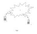
- FIG. 1shows a typical multimedia mobile communications system.
- a first multimedia mobile terminal 1communicates with a second multimedia mobile terminal 2 via a radio link 3 to a mobile communications network 4 .
- Control datais sent between the two terminals 1 , 2 as well as multimedia data.
- FIG. 2shows the typical multimedia components of a terminal 1 .
- the terminalcomprises a video codec 10 , an audio codec 20 , a data protocol manager 30 , a control manager 40 , a multiplexer/demultiplexer 50 and a modem (if required).
- the video codec 10receives signals for coding from a video input/output device 70 of the terminal (e.g. a camera) and receives signals for decoding from a remote terminal 2 for display by the terminal 1 on a display of the video input/output device 70 .
- the audio codec 20receives signals for coding from an audio input/output device 75 , (e.g.
- the terminalmay be a portable radio communications device, such as a radio telephone.
- the control manager 40controls the operation of the video codec 10 , the audio codec 20 and the data protocols manager 30 .
- the inventionsince the invention is concerned with the operation of the video codec 10 , no further discussion of the audio codec 20 and protocol manager 30 will be provided.
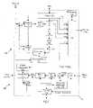
- FIG. 3shows an example of a video codec 10 according to the invention.
- the video codeccomprises an encoder part 100 and a decoder part 200 .
- the encoder part 100comprises an input 101 for receiving a video signal from a camera or video source (not shown) of the terminal 1 .
- a switch 102switches the encoder between an INTRA-mode of coding and an INTER-mode.
- the encoder part 100 of the video codec 10comprises a DCT transformer 103 , a quantiser 104 , an inverse quantiser 108 , an inverse DCT transformer 109 , an adder 110 , one or more picture stores 107 , a subtractor 106 for forming a prediction error, a switch 115 and an encoding control manager 105 .
- the decoder part 200 of the video codec 10comprises an inverse quantiser 220 , an inverse DCT transformer 221 , a motion compensator 222 , a plurality of picture stores 223 and a control 224 .
- the control 224receives video codec control signals demultiplexed from the encoded multimedia stream by the demultiplexer 50 .
- the control 105 of the encoder and the control 224 of the decodermay be the same processor.
- the video codec 10receives a video signal to be encoded.
- the encoder 100 of the video codecencodes the video signal by performing DCT transformation, quantisation and motion compensation.
- the encoded video datais then output to the multiplexer 50 .
- the multiplexer 50multiplexes the video data from the video codec 10 and control data from the control 40 (as well as other signals as appropriate) into a multimedia signal.
- the terminal 1outputs this multimedia signal to the receiving terminal 2 via the modem 60 (if required).
- the video signal from the input 101is transformed into DCT co-efficients by a DCT transformer 103 .
- the DCT coefficientsare then passed to the quantiser 104 where they are quantised.
- Both the switch 102 and the quantiser 104are controlled by the encoding control manager 105 of the video codec, which may also receive feedback control from the receiving terminal 2 by means of the control manager 40 .
- a decoded pictureis then formed by passing the data output by the quantiser through the inverse quantiser 108 and applying an inverse DCT transform 109 to the inverse-quantised data.
- the resulting datais added to the picture store 107 by the adder 110 , switch 115 being operated to present no data to the adder 110 .
- the switch 102is operated to accept from the subtractor 106 the difference between the signal from the input 101 and a reference picture stored in the picture store 107 .
- the difference data output from the subtractor 106represents the prediction error between the current picture and the reference picture stored in the picture store 107 .
- a motion estimator 111may generate motion compensation data from the data in the picture store 107 in a conventional manner.
- the encoding control manager 105decides whether to apply INTRA or INTER coding or whether to code the frame at all on the basis of either the output of the subtractor 106 or in response to feedback control data from a receiving decoder and operates the switch 102 accordingly.
- the encoding control managermay decide not to code a received frame at all when the similarity between the current frame and the reference frame is sufficient or there is not time to code the frame.
- the encoderWhen not responding to feedback control data, the encoder typically encodes a frame as an INTRA-frame either only at the start of coding (all other frames being P-frames), or at regular periods e.g. every 5 s, or when the output of the subtractor exceeds a threshold i.e. when the current picture and that stored in the picture store 107 are judged to be too dissimilar to enable efficient temporal prediction.
- the encodermay also be programmed to encode frames in a particular regular sequence e.g. I B B P B B P B B P B B P B B B I B B P etc.
- the video codecoutputs the quantised DCT coefficients of an INTRA coded picture or prediction error data of an INTER coded picture 112 a , the quantising index 112 b (i.e. the details of the quantiser used), an INTRA/INTER flag 112 c to indicate the mode of coding performed (I or P/B), a transmit flag 112 d to indicate the number of the frame being coded and the motion vectors 112 e in the case of an INTER picture being coded. These are multiplexed together by the multiplexer 50 together with other multimedia signals.
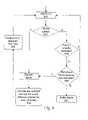
- FIG. 4is a flow diagram illustrating the operation of an encoder according to a first embodiment of the invention.
- the encodercreates one or more temporally predicted frames corresponding to an INTRA coded frame as well as the INTRA coded frame itself.
- the descriptiononly refers to the handling of INTER and INTRA frames.
- the handling of other types of framese.g. B-frames
- B-frameshas been omitted from the description.
- the encoderreceives a frame ( 401 ).
- the encoderdecides (in a conventional manner) whether to code the frame or to skip it ( 402 ). If a decision is made to code the frame, the encoder decides ( 403 ) whether to code the frame as an INTER frame ( 404 ) or an INTRA frame ( 405 ).
- the frameis coded ( 404 ) in a conventional temporally predictive manner.
- the frameis coded ( 405 ) in a conventional non-temporally predictive manner.
- the decision to encode the frame as an INTRA frame ( 405 )may be in response to a periodic INTRA request set up in the encoder or in response to a specific request received from a receiving decoder. Alternatively, it may be in response to the encoder determining that there is significant change in picture content which makes the use of an INTRA picture beneficial from the point of view of compression efficiency. This may also be referred to informally as a scene cut.
- the inventionis applicable whenever a frame or segment of a frame is encoded in an INTRA manner.
- the encoderWhen the encoder encodes a frame as an INTRA frame, the encoder also encodes the frame (or segment of the frame) again ( 407 , 408 ), this time in a temporally predictive manner with reference to another frame within the video sequence.
- a frame that has been INTRA-codedis also encoded ( 407 ) in a temporally predictive manner with reference to a frame occurring within the video sequence temporally prior to the frame to be coded i.e. by forward prediction. This exception may also be the case for the first INTRA coded frame after a scene cut.
- the encoderdetermines ( 406 ) that the frame is the first INTRA frame to be coded (or the first INTRA frame to be coded after a scene cut)
- the encoderencodes the frame again ( 408 ), this time in a predictive manner with reference the INTRA frame that occurs immediately after a visual-content discontinuity e.g. a scene cut).
- the method of selection of a reference picture for such a INTRA-pictureis different from that used for I 4 .
- the second representation of picture 0is an INTER picture predicted (and motion-compensated) with reference to the picture that corresponds to the next periodic INTRA picture (picture 4 in the example).
- a receivermay wait until I 4 and P 0 have been received, after which it can reconstruct picture 0 .
- P 0may be predicted from a picture other than frame I 4 , but prediction from the temporally nearest frame that has been coded in an INTRA manner is preferred.
- the encoded datamay be transmitted in the order in which it is encoded i.e. I 0 , P 1 , P 2 , P 3 , I 4 , P 4 , P 0 , P 5 . . . etc.
- the frames of datamay be re-ordered.
- the terminal 1receives a multimedia signal from the transmitting terminal 2 .
- the demultiplexer 50demultiplexes the multimedia signal and passes the video data to the video codec 10 and the control data to the control manager 40 .
- the decoder 200 of the video codecdecodes the encoded video data by inverse quantising, inverse DCT transforming and motion compensating the data.
- the controller 124 of the decoderchecks the integrity of the received data and, if an error is detected, attempts to conceal the error in a manner to be described below.
- the decoded, corrected and concealed video datais then stored in one of the picture stores 223 and output for reproduction on a display 70 of the receiving terminal 1 .
- Errors in video datamay occur at the picture level, the picture segment level (e.g. GOB (Group of Blocks) or slice level) or the macroblock level. Error checking may be carried out at any or each of these levels. to a frame occurring within the video sequence temporally after the frame to be coded i.e. by backward prediction. The encoder therefore has to wait until a subsequent frame has been received for encoding before it can encode the predicted frame with reference to the subsequent frame.
- GOBGroup of Blocks
- the encoderwaits ( 409 ) until the next INTRA frame has been encoded and then generates ( 408 ) the backward predicted representation of the earlier INTRA-coded frame with reference to the second INTRA frame of the scene.
- All INTRA pictures after the first INTRA picture of a video sequencemay have temporally predicted representation(s) encoded in a forward prediction manner and/or a backward prediction manner.
- FIG. 5shows the frame-by-frame output of an encoder according to the invention.
- I 0is an INTRA coded picture appearing at the very beginning of a video sequence (or after a scene cut).
- the system shownuses periodic INTRA pictures, and I 4 is such a picture.
- a second representation of each INTRA coded pictureis temporally predictively encoded and transmitted.
- the second representation of picture 4is an INTER picture predicted (and motion-compensated) with reference to picture 0 .
- This second representationis indicated by P 4 in FIG. 5 .
- P 4could be predicted from any of the preceding frames, I 0 , P 1 , P 2 , or P 3 .
- Picture 0is preferably chosen because otherwise P 4 would be vulnerable to any transmission errors in the prediction path starting from I 0 .
- a receiving decodercan use any representation of picture 4 to reconstruct a picture for display/reference.
- Picture 0is the first INTRA coded frame of a video sequence. This may be of an entire video sequence or may be the first INTRA coded frame of a subset of an entire video sequence (e.g.
- FIG. 6is a flow chart illustrating a video decoder according to the invention.
- a decoderwhen a decoder according to the invention receives this signal each frame of the signal is decoded in a conventional manner and then displayed on a display means.
- the decoded framemay be error corrected and error concealed in a conventional manner.
- the decoderdetermines when the frame is to be displayed. This may be done by examining a temporal reference (TR) field of the header of the frame or, if the video is transmitted in packets, the time-stamps of the packets may be examined.
- TRtemporal reference
- the decoderreceives picture 10 ( 501 ) and determines ( 602 ) from its picture header that the picture is INTRA-coded.
- the decoderdecodes picture 10 ( 608 ) without reference to any other picture, displays it and stores it in picture store 223 a ( 604 ).
- the decoderthen receives picture P 1 ( 501 ) and determines ( 602 ) from its picture header that the picture is INTER-coded as a P-picture.
- the decoderdetermines whether picture 1 has already been decoded ( 605 ).
- the decoderchecks whether the reference picture for P 1 has been received and decoded ( 606 ). As picture 0 has been received and decoded, the decoder decodes picture P 1 ( 608 ) with reference to the reference picture 0 , displays it and stores it in the next picture store 223 b ( 604 ). The decoder then receives picture P 2 ( 501 ) and determines ( 602 ) from its picture header that the picture is INTER-coded as a P-picture.
- Picture 2has not been decoded ( 605 ) and the reference picture 1 has been decoded ( 606 ) so the decoder therefore decodes picture P 2 with reference to the preceding reference picture 1 , displays it and stores it in the next picture store 223 c and so on.
- the same procedure(steps 602 , 608 , 605 and 606 ) is followed for INTER coded picture P 3 .
- the decoderdetermines ( 602 ) from its picture header that the picture is INTRA-coded and decodes the picture.
- the decoderthen receives picture P 4 ( 501 ) and determines ( 602 ) from its picture header that the picture is INTER-coded as a P-picture. However the decoder notes ( 605 ) that picture 4 has already been successfully decoded and discards picture P 4 and receives the next picture of data P 0 . The decoder determines ( 602 ) from its picture header that the picture is INTER-coded as a P-picture. However the decoder notes ( 605 ) that picture 0 has akeady been decoded, discards picture P 0 and subsequently receives the next picture of data P 5 . This picture is then decoded with reference to decoded picture 4 .
- the decoderWhen 14 is received successfully, the decoder decodes 14 without reference to any other frame. When P 4 is received it is ignored because picture 4 has already been decoded ( 605 ). When P 0 is received the decoder determines that picture 0 has not already been decoded ( 605 ) and that the reference picture for P 0 (picture 4 ) has been decoded ( 606 ). The decoder therefore decodes ( 608 ) frame P 0 with reference to picture 4 . Since picture 0 has now been decoded, it is possible to decode any buffered frames for which picture 0 was the reference picture. Thus the decoder decodes ( 608 ) the buffered frame P 1 with reference to picture 0 . After decoding frame 1 , the decoder is also able to decode the buffered frame P 2 and, after decoding frame 2 , the decoder is also able to decode the buffered frame P 3 .
- the decoderdiscards the buffered frames if the decoder does not receive a reference frame for the buffered frames.
- the decodermay be arranged to discard the buffered frames if the reference picture for the buffered frames is not received within a given time or when an INTRA-coded frame is received.
- FIG. 7is a flow chart also illustrating a second embodiment of a video decoder according to the invention, which is capable of detecting scene changes.
- the decoderreceives ( 701 ) a signal for decoding.
- the decoderdetects ( 702 ) if there has been a scene cut between the latest decoded frame and if the INTRA picture following the scene cut is missing. This may be done for instance by examining a scene identifier in the header of the encoded frame or by examining the picture number of the frame, as set out in Annex W of H.263.
- the decodercan deduce from the picture number that a picture is missing and, if the next picture after a missed one does not indicate a spare reference picture number, the decoder assumes that the lost picture is an INTRA picture associated with a scene cut.
- the decoderchecks ( 703 ) if the frame being decoded is a redundant representation of a frame that has already been decoded (called a sync frame in the figure). In H.263, such a redundant representation may be indicated by giving the encoded frame the same TR as the primary representation of the picture.
- the decoderdecodes the frame ( 705 ) and continues from the beginning of the loop. Otherwise, the decoder skips the decoding and continues from the beginning of the loop ( 701 ).
- the decoderstarts to monitor ( 706 ) for the receipt of the backward-predicted frame corresponding to the first INTRA picture.
- the decoderknows that this particular frame should appear after the next periodic INTRA picture.
- All frames preceding the expected backward-predicted frameare buffered ( 707 ) (in compressed format).
- the bufferingis stopped.
- the next received frameis decoded ( 708 ) if it and the first periodic INTRA picture (i.e. the second INTRA picture in the scene) are received correctly.
- Frame bufferinghas two implications. Firstly, the playback (displaying) process should use buffering to absorb the jitter introduced by the decoding process. This kind of a buffer is typical in video streaming and therefore the invention does not necessarily cause any modifications to the displaying process. Secondly, all buffered frames are decoded as soon as the reference frame is decoded. In practice this means that there may be a burst of computational activity when the first INTRA picture (I 0 ) of a scene is lost and a subsequent representation (P 0 ) of the picture of the scene is decoded. The decoder should be fast enough so that it has the resources to make up the time spent on buffering and so that uncompressed frames do not remain in the buffers for a long time.
- the typical encoding/decoding orderwould be: I0, P1, P2, . . . , Pn ⁇ 1, In, Pn, P0, Pn+1, Pn+2, where I means an INTRA picture, P means an INTER picture, the index corresponds to relative capturing/displaying time, and time instant n corresponds to the first periodic INTRA frame after a scene cut.
- the processing power requirement at the decodercan be minimised by re-ordering the transmitted frames compared with the typical encoding/decoding order, i.e., the transmitter can send the frames in the following order: I0, In, P0, Pn, P1, P2, . . . , Pn ⁇ 1, Pn+1, Pn+2,
- the inventionis applicable to schemes where some segments of a picture are INTRA-coded and others INTER-coded. This is illustrated in FIG. 8 .
- the bit-streamis coded in a conventional manner.
- the encoderdecides to update a picture segment in an INTRA manner, it carries out the following three operations:
- the encodercodes the picture as a normal INTER-picture P(n).
- the encodercodes P(n)′, which is a redundant representation of P(n) where the desired picture segment is INTRA coded and other picture segments remain unchanged from P(n).
- the time-stamp of this newly coded pictureis as close as possible to P(n).
- the encoderencodes P(n)′′, which is a secondary representation of P(n)′.
- P(n)′′the picture segment of P(n)′ that was coded in an INTRA manner is INTER-coded.
- the reference picture usedis the latest picture (other than P(n)′) in which the corresponding segment was INTRA-coded.
- the encodermay limit motion vectors to point only inside the picture segment in order to prevent the propagation of possible decoding errors from the neighbouring segments.
- the encodermay use a coding mode such as H.263 Independent Segment Decoding (Annex R), which inherently prevents prediction from neighbouring picture segments.
- Other picture segments of P(n)′′remain unchanged from P(n).
- the encodercontinues coding normally.
- the decoderoperates similarly to the one described earlier. If the picture segment in P(n) is not corrupted, P(n)′ and P(n)′′ are redundant and may be discarded. Otherwise, the decoder can use either P(n)′ or P(n)′′ to recover the corrupted picture segment.
- the error resilience of the inventioncan be improved if the transmitter sends multiple copies of a temporally predicted frame corresponding to an INTRA frame.
- the multiple copiesmay be predicted from different reference pictures in a forward or backward manner. To maximise error protection, these frames should be encapsulated into different packets.
- each INTRA pictureis associated with both forward- and backward-predicted corresponding pictures.
- the inventioncan be used in conversational, low-delay applications.
- applications that do not buffer decoded frames before displaying thembut rather display decoded frames more or less immediately
- corresponding backward predicted framescannot be used by a decoder.
- a transmitting encoder for such applicationse.g. conversational applications
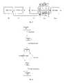
- the systemhas one or more media sources 90 , e.g. a camera and a microphone.
- Multimedia contentcan be synthetically created e.g. animated computer graphics and digitally generated music.
- the raw data captured from the sourcesare edited by an editing system 91 .
- the storage space required for raw multimedia datais huge.
- multimedia clipsare also compressed in the editing system 91 .
- the clipsare handed to a multimedia server 92 .
- a number of clients 93can access the server over a network.
- the server 92is able to respond to requests presented by the clients 93 .
- the main task for the serveris to transmit a desired multimedia clip to a given client.
- the client 93decompresses and plays the clip.
- the clientutilizes one or more output devices 94 , e.g. the screen and the loudspeaker of the client.
- the serverincorporates a video encoder according to the invention and the client incorporates a video decoder according to the invention.
- both the server and the clientsincorporate video codec according to the invention.
- At least part of the link connecting a client 93 and the server 92is wireless e.g. by radio.
- multimedia servers 92have two modes of operation, namely they deliver either pre-stored multimedia clips or live (real-time) multimedia streams.
- clipsare stored on a server database, which is then accessed on an on-demand basis by the server for the client(s).
- multimedia clipsare handed to the server as a continuous media stream that is immediately transmitted to clients 93 .
- a servercan remove and compress some of the header information produced by a multiplexing format as well as encapsulate the media clip into network packets.
- the clients 93control the operation of the server 92 using a control protocol.
- the minimum set of controlsconsists of a function to select a desired media clip.
- serversmay support more advanced controls. For example, clients may be able to stop the transmission of a clip, to pause and resume the transmission of a clip, and to control the media flow if the throughput of the transmission channel varies, in which case the server dynamically adjusts the bit stream to fit into the available bandwidth.
- the client 93receives a compressed and multiplexed media clip from the multimedia server 92 .
- the clientdemultiplexes the clip in order to retrieve the separate media tracks and then decompresses these media tracks.
- the decompressed (reconstructed) media tracksare played on output devices 94 .
- a controller unitinterfaces with an end-user, controls the playback according to the user input and handles client-server control traffic.
- the demultiplexing-decompression-playback chaincan be carried out while still downloading a subsequent part of the clip. This is commonly referred to as streaming.
- the whole clipis downloaded to the client 93 and then the client demultiplexes, decompresses and plays it.
- the inventionis not intended to be limited to the video coding protocols discussed above: these are intended to be merely exemplary.
- the inventionis applicable to any video coding protocol using temporal prediction.
- the addition of additional INTER frames corresponding to INTRA frames as discussed aboveintroduces error resilience into the encoded signal and allows a receiving decoder to select alternative decoding options if part of the received signal is corrupted.
Landscapes
- Engineering & Computer Science (AREA)
- Multimedia (AREA)
- Signal Processing (AREA)
- Compression Or Coding Systems Of Tv Signals (AREA)
- Studio Devices (AREA)
Abstract
Description
I0, P1, P2, . . . , Pn−1, In, Pn, P0, Pn+1, Pn+2,
where I means an INTRA picture, P means an INTER picture, the index corresponds to relative capturing/displaying time, and time instant n corresponds to the first periodic INTRA frame after a scene cut.
I0, In, P0, Pn, P1, P2, . . . , Pn−1, Pn+1, Pn+2,
Claims (39)
Priority Applications (1)
| Application Number | Priority Date | Filing Date | Title |
|---|---|---|---|
| US11/453,498US20060285589A1 (en) | 2000-08-14 | 2006-06-15 | Video coding |
Applications Claiming Priority (2)
| Application Number | Priority Date | Filing Date | Title |
|---|---|---|---|
| GB0019983AGB2366464A (en) | 2000-08-14 | 2000-08-14 | Video coding using intra and inter coding on the same data |
| GB0019983.6 | 2000-08-14 |
Related Child Applications (1)
| Application Number | Title | Priority Date | Filing Date |
|---|---|---|---|
| US11/453,498ContinuationUS20060285589A1 (en) | 2000-08-14 | 2006-06-15 | Video coding |
Publications (2)
| Publication Number | Publication Date |
|---|---|
| US20020054641A1 US20020054641A1 (en) | 2002-05-09 |
| US7116714B2true US7116714B2 (en) | 2006-10-03 |
Family
ID=9897578
Family Applications (2)
| Application Number | Title | Priority Date | Filing Date |
|---|---|---|---|
| US09/924,582Expired - LifetimeUS7116714B2 (en) | 2000-08-14 | 2001-08-09 | Video coding |
| US11/453,498AbandonedUS20060285589A1 (en) | 2000-08-14 | 2006-06-15 | Video coding |
Family Applications After (1)
| Application Number | Title | Priority Date | Filing Date |
|---|---|---|---|
| US11/453,498AbandonedUS20060285589A1 (en) | 2000-08-14 | 2006-06-15 | Video coding |
Country Status (8)
| Country | Link |
|---|---|
| US (2) | US7116714B2 (en) |
| EP (1) | EP1312222A1 (en) |
| JP (1) | JP2004507178A (en) |
| KR (1) | KR100960282B1 (en) |
| CN (2) | CN1812587A (en) |
| AU (1) | AU2001289794A1 (en) |
| GB (1) | GB2366464A (en) |
| WO (1) | WO2002015589A1 (en) |
Cited By (36)
| Publication number | Priority date | Publication date | Assignee | Title |
|---|---|---|---|---|
| US20050021821A1 (en)* | 2001-11-30 | 2005-01-27 | Turnbull Rory Stewart | Data transmission |
| US20050229072A1 (en)* | 2004-03-31 | 2005-10-13 | Setton Ezra J E | Multimedia content delivery using pre-stored multiple description coded video with restart |
| US20060115183A1 (en)* | 2001-08-21 | 2006-06-01 | Canon Kabushiki Kaisha | Image processing apparatus, image input/output apparatus, scaling method and memory control method |
| US20060133514A1 (en)* | 2002-03-27 | 2006-06-22 | Walker Matthew D | Video coding and transmission |
| US20070071398A1 (en)* | 2005-09-27 | 2007-03-29 | Raveendran Vijayalakshmi R | Method and apparatus for progressive channel switching |
| US20070073779A1 (en)* | 2005-09-27 | 2007-03-29 | Walker Gordon K | Channel switch frame |
| US20070088971A1 (en)* | 2005-09-27 | 2007-04-19 | Walker Gordon K | Methods and apparatus for service acquisition |
| US20070130596A1 (en)* | 2005-12-07 | 2007-06-07 | General Instrument Corporation | Method and apparatus for delivering compressed video to subscriber terminals |
| US20080127258A1 (en)* | 2006-11-15 | 2008-05-29 | Qualcomm Incorporated | Systems and methods for applications using channel switch frames |
| US20080170564A1 (en)* | 2006-11-14 | 2008-07-17 | Qualcomm Incorporated | Systems and methods for channel switching |
| US20080187053A1 (en)* | 2007-02-06 | 2008-08-07 | Microsoft Corporation | Scalable multi-thread video decoding |
| US20090003447A1 (en)* | 2007-06-30 | 2009-01-01 | Microsoft Corporation | Innovations in video decoder implementations |
| US20090002379A1 (en)* | 2007-06-30 | 2009-01-01 | Microsoft Corporation | Video decoding implementations for a graphics processing unit |
| US7474699B2 (en)* | 2001-08-28 | 2009-01-06 | Ntt Docomo, Inc. | Moving picture encoding/transmission system, moving picture encoding/transmission method, and encoding apparatus, decoding apparatus, encoding method decoding method and program usable for the same |
| US20090296812A1 (en)* | 2008-05-28 | 2009-12-03 | Korea Polytechnic University Industry Academic Cooperation Foundation | Fast encoding method and system using adaptive intra prediction |
| US20100002776A1 (en)* | 2008-07-01 | 2010-01-07 | Lee Kun-Bin | Method and apparatus for storing decoded moving pictures with a reduced memory requirement |
| US7761901B2 (en) | 2003-03-19 | 2010-07-20 | British Telecommunications Plc | Data transmission |
| US7974200B2 (en) | 2000-11-29 | 2011-07-05 | British Telecommunications Public Limited Company | Transmitting and receiving real-time data |
| US20110221959A1 (en)* | 2010-03-11 | 2011-09-15 | Raz Ben Yehuda | Method and system for inhibiting audio-video synchronization delay |
| US8135852B2 (en) | 2002-03-27 | 2012-03-13 | British Telecommunications Public Limited Company | Data streaming system and method |
| US8270473B2 (en) | 2009-06-12 | 2012-09-18 | Microsoft Corporation | Motion based dynamic resolution multiple bit rate video encoding |
| US8311115B2 (en) | 2009-01-29 | 2012-11-13 | Microsoft Corporation | Video encoding using previously calculated motion information |
| US8396114B2 (en) | 2009-01-29 | 2013-03-12 | Microsoft Corporation | Multiple bit rate video encoding using variable bit rate and dynamic resolution for adaptive video streaming |
| US8700792B2 (en) | 2008-01-31 | 2014-04-15 | General Instrument Corporation | Method and apparatus for expediting delivery of programming content over a broadband network |
| US8705616B2 (en) | 2010-06-11 | 2014-04-22 | Microsoft Corporation | Parallel multiple bitrate video encoding to reduce latency and dependences between groups of pictures |
| US8731067B2 (en) | 2011-08-31 | 2014-05-20 | Microsoft Corporation | Memory management for video decoding |
| US8752092B2 (en) | 2008-06-27 | 2014-06-10 | General Instrument Corporation | Method and apparatus for providing low resolution images in a broadcast system |
| US8837600B2 (en) | 2011-06-30 | 2014-09-16 | Microsoft Corporation | Reducing latency in video encoding and decoding |
| US8885729B2 (en) | 2010-12-13 | 2014-11-11 | Microsoft Corporation | Low-latency video decoding |
| US20150078673A1 (en)* | 2013-09-16 | 2015-03-19 | Zhigang Xia | Grouping and compressing similar photos |
| US9106468B1 (en)* | 2009-01-30 | 2015-08-11 | Sprint Communications Company L.P. | Transferring media objects from one device to another device |
| US9413664B1 (en) | 2008-09-23 | 2016-08-09 | Spring Communications Company L.P. | Resuming media objects delivered via streaming services upon data loss events |
| US9591318B2 (en) | 2011-09-16 | 2017-03-07 | Microsoft Technology Licensing, Llc | Multi-layer encoding and decoding |
| US9706214B2 (en) | 2010-12-24 | 2017-07-11 | Microsoft Technology Licensing, Llc | Image and video decoding implementations |
| US9819949B2 (en) | 2011-12-16 | 2017-11-14 | Microsoft Technology Licensing, Llc | Hardware-accelerated decoding of scalable video bitstreams |
| US11089343B2 (en) | 2012-01-11 | 2021-08-10 | Microsoft Technology Licensing, Llc | Capability advertisement, configuration and control for video coding and decoding |
Families Citing this family (33)
| Publication number | Priority date | Publication date | Assignee | Title |
|---|---|---|---|---|
| JP4135395B2 (en)* | 2002-04-26 | 2008-08-20 | 日本電気株式会社 | Encoded packet transmission receiving method and apparatus and program thereof |
| EP1501314A4 (en)* | 2002-04-26 | 2010-03-17 | Nec Corp | Moving image transferring system, moving image encoding apparatus, moving image decoding apparatus, and moving image transferring program |
| FI114679B (en)* | 2002-04-29 | 2004-11-30 | Nokia Corp | Direct access points for video coding |
| CA2492751C (en)* | 2002-07-16 | 2012-06-12 | Nokia Corporation | A method for random access and gradual picture refresh in video coding |
| US7949047B2 (en) | 2003-03-17 | 2011-05-24 | Qualcomm Incorporated | System and method for partial intraframe encoding for wireless multimedia transmission |
| US7724818B2 (en)* | 2003-04-30 | 2010-05-25 | Nokia Corporation | Method for coding sequences of pictures |
| US7634146B2 (en) | 2003-10-20 | 2009-12-15 | Logitech Europe S.A. | Methods and apparatus for encoding and decoding video data |
| US7826526B2 (en) | 2003-10-20 | 2010-11-02 | Logitech Europe S.A. | Methods and apparatus for encoding and decoding video data |
| US8116370B2 (en) | 2003-10-20 | 2012-02-14 | Logitech Europe S.A. | Methods and apparatus for encoding and decoding video data |
| US20060050695A1 (en)* | 2004-09-07 | 2006-03-09 | Nokia Corporation | System and method for using redundant representations in streaming applications |
| WO2006075302A1 (en)* | 2005-01-17 | 2006-07-20 | Koninklijke Philips Electronics N.V. | System, transmitter, receiver, method and software for transmitting and receiving ordered sets of video frames |
| US7738468B2 (en) | 2005-03-22 | 2010-06-15 | Logitech Europe S.A. | Method and apparatus for packet traversal of a network address translation device |
| KR100694137B1 (en) | 2005-07-08 | 2007-03-12 | 삼성전자주식회사 | A video encoding apparatus, a video decoding apparatus, and a method thereof, and a recording medium having recorded thereon a program for implementing the same. |
| TWI279143B (en)* | 2005-07-11 | 2007-04-11 | Softfoundry Internat Ptd Ltd | Integrated compensation method of video code flow |
| EP2293572A1 (en)* | 2005-09-27 | 2011-03-09 | Qualcomm Incorporated | Channel switch frame |
| BRPI0710236A2 (en)* | 2006-05-03 | 2011-08-09 | Ericsson Telefon Ab L M | media reconstruction method and apparatus, computer program product, apparatus for creating a media representation, random access point data object, and media representation and document or container |
| US8520733B2 (en) | 2006-06-30 | 2013-08-27 | Core Wireless Licensing S.A.R.L | Video coding |
| FR2910211A1 (en)* | 2006-12-19 | 2008-06-20 | Canon Kk | METHODS AND DEVICES FOR RE-SYNCHRONIZING A DAMAGED VIDEO STREAM |
| US20080152014A1 (en)* | 2006-12-21 | 2008-06-26 | On Demand Microelectronics | Method and apparatus for encoding and decoding of video streams |
| EP2137972A2 (en)* | 2007-04-24 | 2009-12-30 | Nokia Corporation | System and method for implementing fast tune-in with intra-coded redundant pictures |
| KR101155587B1 (en)* | 2008-12-19 | 2012-06-19 | 주식회사 케이티 | APPARATUS AND METHOD for RESTORING TRANSMISSION ERROR |
| US9532059B2 (en) | 2010-10-05 | 2016-12-27 | Google Technology Holdings LLC | Method and apparatus for spatial scalability for video coding |
| CN102655604B (en)* | 2011-03-03 | 2016-06-22 | 华为技术有限公司 | Method for processing video frequency and equipment |
| US8989256B2 (en) | 2011-05-25 | 2015-03-24 | Google Inc. | Method and apparatus for using segmentation-based coding of prediction information |
| EP2751990A4 (en) | 2011-08-29 | 2015-04-22 | Icvt Ltd | CONTROL OF A VIDEO CONTENT SYSTEM |
| CA2855177A1 (en)* | 2011-11-25 | 2013-05-30 | Thomson Licensing | Video quality assessment considering scene cut artifacts |
| US9247257B1 (en) | 2011-11-30 | 2016-01-26 | Google Inc. | Segmentation based entropy encoding and decoding |
| US9094681B1 (en) | 2012-02-28 | 2015-07-28 | Google Inc. | Adaptive segmentation |
| US8396127B1 (en)* | 2012-06-27 | 2013-03-12 | Google Inc. | Segmentation for video coding using predictive benefit |
| JP5885604B2 (en)* | 2012-07-06 | 2016-03-15 | 株式会社Nttドコモ | Moving picture predictive coding apparatus, moving picture predictive coding method, moving picture predictive coding program, moving picture predictive decoding apparatus, moving picture predictive decoding method, and moving picture predictive decoding program |
| US9332276B1 (en) | 2012-08-09 | 2016-05-03 | Google Inc. | Variable-sized super block based direct prediction mode |
| US9380298B1 (en) | 2012-08-10 | 2016-06-28 | Google Inc. | Object-based intra-prediction |
| CN105103554A (en) | 2013-03-28 | 2015-11-25 | 华为技术有限公司 | Method for protecting sequence of video frames against packet loss |
Citations (8)
| Publication number | Priority date | Publication date | Assignee | Title |
|---|---|---|---|---|
| US5436664A (en) | 1992-09-18 | 1995-07-25 | Sgs-Thomson Microelectronics S.A. | Method for masking transmission errors of MPEG compressed pictures |
| US5442400A (en) | 1993-04-29 | 1995-08-15 | Rca Thomson Licensing Corporation | Error concealment apparatus for MPEG-like video data |
| US5680322A (en) | 1994-05-30 | 1997-10-21 | Matsushita Electric Industrial Co., Ltd. | Method and apparatus for dynamic image data transmission |
| EP0920214A2 (en) | 1997-11-28 | 1999-06-02 | Victor Company Of Japan, Ltd. | Apparatus and method of coding/decoding moving picture |
| US6028631A (en)* | 1997-09-08 | 2000-02-22 | Hitachi, Ltd. | Portable terminal apparatus for multimedia communication |
| US6404814B1 (en)* | 2000-04-28 | 2002-06-11 | Hewlett-Packard Company | Transcoding method and transcoder for transcoding a predictively-coded object-based picture signal to a predictively-coded block-based picture signal |
| US6591014B1 (en)* | 1998-07-13 | 2003-07-08 | Nec Corporation | Apparatus for coding moving picture |
| US6611561B1 (en)* | 1999-02-18 | 2003-08-26 | Nokia Mobile Phones Limited | Video coding |
- 2000
- 2000-08-14GBGB0019983Apatent/GB2366464A/ennot_activeWithdrawn
- 2001
- 2001-08-09JPJP2002520569Apatent/JP2004507178A/ennot_activeWithdrawn
- 2001-08-09EPEP01969581Apatent/EP1312222A1/ennot_activeWithdrawn
- 2001-08-09CNCNA2005101316318Apatent/CN1812587A/enactivePending
- 2001-08-09USUS09/924,582patent/US7116714B2/ennot_activeExpired - Lifetime
- 2001-08-09CNCNB018173306Apatent/CN1242623C/ennot_activeExpired - Fee Related
- 2001-08-09AUAU2001289794Apatent/AU2001289794A1/ennot_activeAbandoned
- 2001-08-09WOPCT/EP2001/009220patent/WO2002015589A1/enactiveApplication Filing
- 2001-08-09KRKR1020037002040Apatent/KR100960282B1/ennot_activeExpired - Fee Related
- 2006
- 2006-06-15USUS11/453,498patent/US20060285589A1/ennot_activeAbandoned
Patent Citations (8)
| Publication number | Priority date | Publication date | Assignee | Title |
|---|---|---|---|---|
| US5436664A (en) | 1992-09-18 | 1995-07-25 | Sgs-Thomson Microelectronics S.A. | Method for masking transmission errors of MPEG compressed pictures |
| US5442400A (en) | 1993-04-29 | 1995-08-15 | Rca Thomson Licensing Corporation | Error concealment apparatus for MPEG-like video data |
| US5680322A (en) | 1994-05-30 | 1997-10-21 | Matsushita Electric Industrial Co., Ltd. | Method and apparatus for dynamic image data transmission |
| US6028631A (en)* | 1997-09-08 | 2000-02-22 | Hitachi, Ltd. | Portable terminal apparatus for multimedia communication |
| EP0920214A2 (en) | 1997-11-28 | 1999-06-02 | Victor Company Of Japan, Ltd. | Apparatus and method of coding/decoding moving picture |
| US6591014B1 (en)* | 1998-07-13 | 2003-07-08 | Nec Corporation | Apparatus for coding moving picture |
| US6611561B1 (en)* | 1999-02-18 | 2003-08-26 | Nokia Mobile Phones Limited | Video coding |
| US6404814B1 (en)* | 2000-04-28 | 2002-06-11 | Hewlett-Packard Company | Transcoding method and transcoder for transcoding a predictively-coded object-based picture signal to a predictively-coded block-based picture signal |
Non-Patent Citations (4)
| Title |
|---|
| Esteban Rodriguez-Market et al, entitled Video Coding Over Packet-Erasure Channels, School of EECS, Washington STate University, Pullman, WA 99164-2752, 0-8186-8821-1/98 (C) 1998 IEEE, pp. 314-318. |
| European Search Report. |
| Kim C-S et al., "An Error Detection And Recovery Algorithem For Compressed Video Signal Using Source Level Redundancy" IEEE Transactions on Image Processing, IEEE Inc., New York, US, vol. 9, No. 2, Feb. 2000, pp. 209-219; XP000912583 ISSN: 1057-7149 and Abstract. |
| PCT International Search Report Reference No.: PAT00409/PCT; International Application No. PCT/EP01/09220; Applicant: Nokia Mobile Phones Limited. |
Cited By (65)
| Publication number | Priority date | Publication date | Assignee | Title |
|---|---|---|---|---|
| US7974200B2 (en) | 2000-11-29 | 2011-07-05 | British Telecommunications Public Limited Company | Transmitting and receiving real-time data |
| US20060115183A1 (en)* | 2001-08-21 | 2006-06-01 | Canon Kabushiki Kaisha | Image processing apparatus, image input/output apparatus, scaling method and memory control method |
| US7286720B2 (en)* | 2001-08-21 | 2007-10-23 | Canon Kabushiki Kaisha | Image processing apparatus, image input/output apparatus, scaling method and memory control method |
| US7474699B2 (en)* | 2001-08-28 | 2009-01-06 | Ntt Docomo, Inc. | Moving picture encoding/transmission system, moving picture encoding/transmission method, and encoding apparatus, decoding apparatus, encoding method decoding method and program usable for the same |
| US20050021821A1 (en)* | 2001-11-30 | 2005-01-27 | Turnbull Rory Stewart | Data transmission |
| US20060133514A1 (en)* | 2002-03-27 | 2006-06-22 | Walker Matthew D | Video coding and transmission |
| US8386631B2 (en) | 2002-03-27 | 2013-02-26 | British Telecommunications Plc | Data streaming system and method |
| US8135852B2 (en) | 2002-03-27 | 2012-03-13 | British Telecommunications Public Limited Company | Data streaming system and method |
| US7761901B2 (en) | 2003-03-19 | 2010-07-20 | British Telecommunications Plc | Data transmission |
| US20050229072A1 (en)* | 2004-03-31 | 2005-10-13 | Setton Ezra J E | Multimedia content delivery using pre-stored multiple description coded video with restart |
| US7676722B2 (en)* | 2004-03-31 | 2010-03-09 | Sony Corporation | Multimedia content delivery using pre-stored multiple description coded video with restart |
| US9467659B2 (en)* | 2005-09-27 | 2016-10-11 | Qualcomm Incorporated | Method and apparatus for progressive channel switching |
| US20070088971A1 (en)* | 2005-09-27 | 2007-04-19 | Walker Gordon K | Methods and apparatus for service acquisition |
| US8670437B2 (en) | 2005-09-27 | 2014-03-11 | Qualcomm Incorporated | Methods and apparatus for service acquisition |
| US8612498B2 (en)* | 2005-09-27 | 2013-12-17 | Qualcomm, Incorporated | Channel switch frame |
| US20070071398A1 (en)* | 2005-09-27 | 2007-03-29 | Raveendran Vijayalakshmi R | Method and apparatus for progressive channel switching |
| US20120294360A1 (en)* | 2005-09-27 | 2012-11-22 | Qualcomm Incorporated | Channel switch frame |
| US8229983B2 (en)* | 2005-09-27 | 2012-07-24 | Qualcomm Incorporated | Channel switch frame |
| US20070073779A1 (en)* | 2005-09-27 | 2007-03-29 | Walker Gordon K | Channel switch frame |
| US20070130596A1 (en)* | 2005-12-07 | 2007-06-07 | General Instrument Corporation | Method and apparatus for delivering compressed video to subscriber terminals |
| US8340098B2 (en)* | 2005-12-07 | 2012-12-25 | General Instrument Corporation | Method and apparatus for delivering compressed video to subscriber terminals |
| US20080170564A1 (en)* | 2006-11-14 | 2008-07-17 | Qualcomm Incorporated | Systems and methods for channel switching |
| US8345743B2 (en) | 2006-11-14 | 2013-01-01 | Qualcomm Incorporated | Systems and methods for channel switching |
| US8761162B2 (en) | 2006-11-15 | 2014-06-24 | Qualcomm Incorporated | Systems and methods for applications using channel switch frames |
| US20080127258A1 (en)* | 2006-11-15 | 2008-05-29 | Qualcomm Incorporated | Systems and methods for applications using channel switch frames |
| US8411734B2 (en) | 2007-02-06 | 2013-04-02 | Microsoft Corporation | Scalable multi-thread video decoding |
| US8743948B2 (en) | 2007-02-06 | 2014-06-03 | Microsoft Corporation | Scalable multi-thread video decoding |
| US9161034B2 (en) | 2007-02-06 | 2015-10-13 | Microsoft Technology Licensing, Llc | Scalable multi-thread video decoding |
| US20080187053A1 (en)* | 2007-02-06 | 2008-08-07 | Microsoft Corporation | Scalable multi-thread video decoding |
| US10567770B2 (en) | 2007-06-30 | 2020-02-18 | Microsoft Technology Licensing, Llc | Video decoding implementations for a graphics processing unit |
| US9554134B2 (en) | 2007-06-30 | 2017-01-24 | Microsoft Technology Licensing, Llc | Neighbor determination in video decoding |
| US9648325B2 (en) | 2007-06-30 | 2017-05-09 | Microsoft Technology Licensing, Llc | Video decoding implementations for a graphics processing unit |
| US8265144B2 (en) | 2007-06-30 | 2012-09-11 | Microsoft Corporation | Innovations in video decoder implementations |
| US9819970B2 (en) | 2007-06-30 | 2017-11-14 | Microsoft Technology Licensing, Llc | Reducing memory consumption during video decoding |
| US20090003447A1 (en)* | 2007-06-30 | 2009-01-01 | Microsoft Corporation | Innovations in video decoder implementations |
| US20090002379A1 (en)* | 2007-06-30 | 2009-01-01 | Microsoft Corporation | Video decoding implementations for a graphics processing unit |
| US8700792B2 (en) | 2008-01-31 | 2014-04-15 | General Instrument Corporation | Method and apparatus for expediting delivery of programming content over a broadband network |
| US20090296812A1 (en)* | 2008-05-28 | 2009-12-03 | Korea Polytechnic University Industry Academic Cooperation Foundation | Fast encoding method and system using adaptive intra prediction |
| US8331449B2 (en)* | 2008-05-28 | 2012-12-11 | Korea Polytechnic University Industry Academic Cooperation Foundation | Fast encoding method and system using adaptive intra prediction |
| US8752092B2 (en) | 2008-06-27 | 2014-06-10 | General Instrument Corporation | Method and apparatus for providing low resolution images in a broadcast system |
| US8638844B2 (en)* | 2008-07-01 | 2014-01-28 | Mediatek Inc. | Method and apparatus for storing decoded moving pictures with a reduced memory requirement |
| US20100002776A1 (en)* | 2008-07-01 | 2010-01-07 | Lee Kun-Bin | Method and apparatus for storing decoded moving pictures with a reduced memory requirement |
| US9413664B1 (en) | 2008-09-23 | 2016-08-09 | Spring Communications Company L.P. | Resuming media objects delivered via streaming services upon data loss events |
| US8396114B2 (en) | 2009-01-29 | 2013-03-12 | Microsoft Corporation | Multiple bit rate video encoding using variable bit rate and dynamic resolution for adaptive video streaming |
| US8311115B2 (en) | 2009-01-29 | 2012-11-13 | Microsoft Corporation | Video encoding using previously calculated motion information |
| US9106468B1 (en)* | 2009-01-30 | 2015-08-11 | Sprint Communications Company L.P. | Transferring media objects from one device to another device |
| US8270473B2 (en) | 2009-06-12 | 2012-09-18 | Microsoft Corporation | Motion based dynamic resolution multiple bit rate video encoding |
| US20110221959A1 (en)* | 2010-03-11 | 2011-09-15 | Raz Ben Yehuda | Method and system for inhibiting audio-video synchronization delay |
| US9357244B2 (en) | 2010-03-11 | 2016-05-31 | Arris Enterprises, Inc. | Method and system for inhibiting audio-video synchronization delay |
| US8705616B2 (en) | 2010-06-11 | 2014-04-22 | Microsoft Corporation | Parallel multiple bitrate video encoding to reduce latency and dependences between groups of pictures |
| US8885729B2 (en) | 2010-12-13 | 2014-11-11 | Microsoft Corporation | Low-latency video decoding |
| US9706214B2 (en) | 2010-12-24 | 2017-07-11 | Microsoft Technology Licensing, Llc | Image and video decoding implementations |
| US9729898B2 (en) | 2011-06-30 | 2017-08-08 | Mircosoft Technology Licensing, LLC | Reducing latency in video encoding and decoding |
| US8837600B2 (en) | 2011-06-30 | 2014-09-16 | Microsoft Corporation | Reducing latency in video encoding and decoding |
| US10003824B2 (en) | 2011-06-30 | 2018-06-19 | Microsoft Technology Licensing, Llc | Reducing latency in video encoding and decoding |
| US9426495B2 (en) | 2011-06-30 | 2016-08-23 | Microsoft Technology Licensing, Llc | Reducing latency in video encoding and decoding |
| US9743114B2 (en) | 2011-06-30 | 2017-08-22 | Microsoft Technology Licensing, Llc | Reducing latency in video encoding and decoding |
| US9210421B2 (en) | 2011-08-31 | 2015-12-08 | Microsoft Technology Licensing, Llc | Memory management for video decoding |
| US8731067B2 (en) | 2011-08-31 | 2014-05-20 | Microsoft Corporation | Memory management for video decoding |
| US9769485B2 (en) | 2011-09-16 | 2017-09-19 | Microsoft Technology Licensing, Llc | Multi-layer encoding and decoding |
| US9591318B2 (en) | 2011-09-16 | 2017-03-07 | Microsoft Technology Licensing, Llc | Multi-layer encoding and decoding |
| US9819949B2 (en) | 2011-12-16 | 2017-11-14 | Microsoft Technology Licensing, Llc | Hardware-accelerated decoding of scalable video bitstreams |
| US11089343B2 (en) | 2012-01-11 | 2021-08-10 | Microsoft Technology Licensing, Llc | Capability advertisement, configuration and control for video coding and decoding |
| US20150078673A1 (en)* | 2013-09-16 | 2015-03-19 | Zhigang Xia | Grouping and compressing similar photos |
| US9330112B2 (en)* | 2013-09-16 | 2016-05-03 | Intel Corporation | Grouping and compressing similar photos |
Also Published As
| Publication number | Publication date |
|---|---|
| CN1470133A (en) | 2004-01-21 |
| JP2004507178A (en) | 2004-03-04 |
| EP1312222A1 (en) | 2003-05-21 |
| KR20030025285A (en) | 2003-03-28 |
| US20020054641A1 (en) | 2002-05-09 |
| CN1242623C (en) | 2006-02-15 |
| AU2001289794A1 (en) | 2002-02-25 |
| WO2002015589A1 (en) | 2002-02-21 |
| GB2366464A (en) | 2002-03-06 |
| GB0019983D0 (en) | 2000-10-04 |
| CN1812587A (en) | 2006-08-02 |
| US20060285589A1 (en) | 2006-12-21 |
| KR100960282B1 (en) | 2010-06-07 |
Similar Documents
| Publication | Publication Date | Title |
|---|---|---|
| US7116714B2 (en) | Video coding | |
| KR100929558B1 (en) | Video coding method, decoding method, encoder, decoder, wireless communication device and multimedia terminal device | |
| KR100878057B1 (en) | Video encoding | |
| KR100495820B1 (en) | Video coding | |
| JP2006518127A (en) | Picture decoding method | |
| KR20050122281A (en) | Picture coding method | |
| HK1136125A (en) | Video coding | |
| HK1136125B (en) | Video coding |
Legal Events
| Date | Code | Title | Description |
|---|---|---|---|
| AS | Assignment | Owner name:NOKIA CORPORATION, FINLAND Free format text:ASSIGNMENT OF ASSIGNORS INTEREST;ASSIGNOR:HANNUKSELA, MISKA;REEL/FRAME:012246/0673 Effective date:20011004 | |
| STCF | Information on status: patent grant | Free format text:PATENTED CASE | |
| FPAY | Fee payment | Year of fee payment:4 | |
| FPAY | Fee payment | Year of fee payment:8 | |
| AS | Assignment | Owner name:NOKIA TECHNOLOGIES OY, FINLAND Free format text:ASSIGNMENT OF ASSIGNORS INTEREST;ASSIGNOR:NOKIA CORPORATION;REEL/FRAME:035235/0685 Effective date:20150116 | |
| AS | Assignment | Owner name:OMEGA CREDIT OPPORTUNITIES MASTER FUND, LP, NEW YORK Free format text:SECURITY INTEREST;ASSIGNOR:WSOU INVESTMENTS, LLC;REEL/FRAME:043966/0574 Effective date:20170822 Owner name:OMEGA CREDIT OPPORTUNITIES MASTER FUND, LP, NEW YO Free format text:SECURITY INTEREST;ASSIGNOR:WSOU INVESTMENTS, LLC;REEL/FRAME:043966/0574 Effective date:20170822 | |
| AS | Assignment | Owner name:WSOU INVESTMENTS, LLC, CALIFORNIA Free format text:ASSIGNMENT OF ASSIGNORS INTEREST;ASSIGNOR:NOKIA TECHNOLOGIES OY;REEL/FRAME:043953/0822 Effective date:20170722 | |
| FEPP | Fee payment procedure | Free format text:MAINTENANCE FEE REMINDER MAILED (ORIGINAL EVENT CODE: REM.) | |
| FEPP | Fee payment procedure | Free format text:11.5 YR SURCHARGE- LATE PMT W/IN 6 MO, LARGE ENTITY (ORIGINAL EVENT CODE: M1556); ENTITY STATUS OF PATENT OWNER: LARGE ENTITY | |
| MAFP | Maintenance fee payment | Free format text:PAYMENT OF MAINTENANCE FEE, 12TH YEAR, LARGE ENTITY (ORIGINAL EVENT CODE: M1553); ENTITY STATUS OF PATENT OWNER: LARGE ENTITY Year of fee payment:12 | |
| AS | Assignment | Owner name:BP FUNDING TRUST, SERIES SPL-VI, NEW YORK Free format text:SECURITY INTEREST;ASSIGNOR:WSOU INVESTMENTS, LLC;REEL/FRAME:049235/0068 Effective date:20190516 | |
| AS | Assignment | Owner name:WSOU INVESTMENTS, LLC, CALIFORNIA Free format text:RELEASE BY SECURED PARTY;ASSIGNOR:OCO OPPORTUNITIES MASTER FUND, L.P. (F/K/A OMEGA CREDIT OPPORTUNITIES MASTER FUND LP;REEL/FRAME:049246/0405 Effective date:20190516 | |
| AS | Assignment | Owner name:OT WSOU TERRIER HOLDINGS, LLC, CALIFORNIA Free format text:SECURITY INTEREST;ASSIGNOR:WSOU INVESTMENTS, LLC;REEL/FRAME:056990/0081 Effective date:20210528 | |
| AS | Assignment | Owner name:WSOU INVESTMENTS, LLC, CALIFORNIA Free format text:RELEASE BY SECURED PARTY;ASSIGNOR:TERRIER SSC, LLC;REEL/FRAME:056526/0093 Effective date:20210528 | |
| IPR | Aia trial proceeding filed before the patent and appeal board: inter partes review | Free format text:TRIAL NO: IPR2021-00965 Opponent name:CANON, INC., ANDCANON U.S.A., INC. Effective date:20210517 | |
| IPRC | Trial and appeal board: inter partes review certificate | Kind code of ref document:K1 Free format text:INTER PARTES REVIEW CERTIFICATE; TRIAL NO. IPR2021-00965, MAY 17, 2021 INTER PARTES REVIEW CERTIFICATE FOR PATENT 7,116,714, ISSUED OCT. 3, 2006, APPL. NO. 09/924,582, AUG. 9, 2001 INTER PARTES REVIEW CERTIFICATE ISSUED MAR. 7, 2023 Effective date:20230307 |