US7116229B1 - Programming a remote control device using RFID technology - Google Patents
Programming a remote control device using RFID technologyDownload PDFInfo
- Publication number
- US7116229B1 US7116229B1US10/814,708US81470804AUS7116229B1US 7116229 B1US7116229 B1US 7116229B1US 81470804 AUS81470804 AUS 81470804AUS 7116229 B1US7116229 B1US 7116229B1
- Authority
- US
- United States
- Prior art keywords
- codeset
- remote control
- control device
- complete
- programming signal
- Prior art date
- Legal status (The legal status is an assumption and is not a legal conclusion. Google has not performed a legal analysis and makes no representation as to the accuracy of the status listed.)
- Expired - Lifetime, expires
Links
- 238000005516engineering processMethods0.000titledescription7
- 230000008878couplingEffects0.000claimsdescription27
- 238000010168coupling processMethods0.000claimsdescription27
- 238000005859coupling reactionMethods0.000claimsdescription27
- 238000000034methodMethods0.000claimsdescription12
- 238000009432framingMethods0.000claimsdescription9
- 238000010521absorption reactionMethods0.000abstractdescription4
- 230000006870functionEffects0.000description15
- 238000003825pressingMethods0.000description7
- 239000003990capacitorSubstances0.000description6
- 238000010586diagramMethods0.000description6
- 230000001276controlling effectEffects0.000description3
- 230000001939inductive effectEffects0.000description3
- RYGMFSIKBFXOCR-UHFFFAOYSA-NCopperChemical compound[Cu]RYGMFSIKBFXOCR-UHFFFAOYSA-N0.000description2
- 239000000284extractSubstances0.000description2
- 230000001105regulatory effectEffects0.000description2
- 239000004065semiconductorSubstances0.000description2
- 230000003213activating effectEffects0.000description1
- 230000006978adaptationEffects0.000description1
- 238000004891communicationMethods0.000description1
- 238000011161developmentMethods0.000description1
- 230000005684electric fieldEffects0.000description1
- 230000002452interceptive effectEffects0.000description1
- 238000004519manufacturing processMethods0.000description1
- 230000007246mechanismEffects0.000description1
- 238000012986modificationMethods0.000description1
- 230000004048modificationEffects0.000description1
- 238000004806packaging method and processMethods0.000description1
- 238000012856packingMethods0.000description1
- 230000010363phase shiftEffects0.000description1
- 238000012546transferMethods0.000description1
Images


Classifications
- H—ELECTRICITY
- H04—ELECTRIC COMMUNICATION TECHNIQUE
- H04B—TRANSMISSION
- H04B1/00—Details of transmission systems, not covered by a single one of groups H04B3/00 - H04B13/00; Details of transmission systems not characterised by the medium used for transmission
- H04B1/06—Receivers
- H04B1/16—Circuits
- H04B1/20—Circuits for coupling gramophone pick-up, recorder output, or microphone to receiver
- H04B1/202—Circuits for coupling gramophone pick-up, recorder output, or microphone to receiver by remote control
- G—PHYSICS
- G08—SIGNALLING
- G08C—TRANSMISSION SYSTEMS FOR MEASURED VALUES, CONTROL OR SIMILAR SIGNALS
- G08C2201/00—Transmission systems of control signals via wireless link
- G08C2201/20—Binding and programming of remote control devices
Definitions
- the present inventionrelates generally to remote control devices and, more specifically, to programming remote control devices with codeset data.
- a remote control devicetypically controls a selected electronic consumer device by transmitting infrared operational signals to the selected electronic consumer device.
- the operational signalscontain key codes of a codeset associated with the selected electronic consumer device.
- Each key codecorresponds to a function of the selected electronic consumer device, such as power on, power off, volume up, volume down, mute, play, stop, select, channel up, channel down, etc.
- manufacturerssometimes use distinct codesets for the communication between various electronic consumer devices and their associated remote control devices.
- the codesetscan differ from each other not only by the bit patterns assigned to various functions of the associated electronic consumer device, but also by the timing information that describes how the key codes are modulated onto carrier signals to generate operational signals.
- a consumermay find it inconvenient to operate their electronic consumer devices using multiple remote control devices. Thus, a consumer may wish to operate multiple electronic consumer devices using a single remote control device.
- a single remote control devicecan store many codesets so that the remote control device can control a corresponding large number of different electronic consumer devices. There are, however, thousands of codesets in use in electronic consumer devices today. A consumer might find it tedious and confusing to program a single remote control device with all of the appropriate codesets for the electronic consumer devices in his household.
- a methodis sought for easily programming a remote control device to operate various selected electronic consumer devices.
- a systemfacilitates easy programming of a remote control device so that the remote control is usable to control an electronic consumer device.
- the systemincludes a radio frequency identification (RFID) reader (for example, that is built into the remote control device) and a passive RFID transponder (for example, that is built into or affixed to the electronic consumer device).
- RFIDradio frequency identification
- multiple codesetsare stored in a memory of the remote control device.
- the multiple codesetsinclude one particular codeset that is usable to control the electronic consumer device.
- the codesetincludes codeset key data for various functions of the electronic consumer device.
- a designation of this codesetis stored in the RFID transponder, along with a one-digit device number. The designation may, for example, be a three-digit number.
- the RFID reader in the remote control deviceinterrogates the RFID transponder in the electronic consumer device.
- the remote control deviceis brought into close proximity to the RFID transponder in the electronic consumer device and a program key on the remote control pressed, thereby causing the RFID reader within the remote control device to transmit an interrogation signal to the RFID transponder.
- the interrogation signalimparts energy to the RFID transponder.
- the RFID transponderis not powered by a power source, but rather is powered by energy in the interrogation signal. In one example, the energy is conveyed by inductive coupling of an alternating magnetic field generated by the RFID reader.
- the RFID transponderuses the energy conveyed by the RFID reader to power circuitry that generates a programming signal.
- the programming signalincludes the designation of the particular codeset, along with the one-digit device number.
- the RFID reader in the remote control devicereceives the programming signal, extracts the designation of the codeset, and uses the designation to select the corresponding one of the codesets stored in the memory on the remote control device that is usable to control the electronic consumer device.
- the remote control deviceuses key data of the selected codeset to generate an operational signal.
- the remote control devicetransmits the operational signal to the electronic consumer device, thereby controlling the corresponding function of the electronic consumer device. In this way, a designation of the codeset, along with a one-digit device number, is read from an RFID transponder into a remote control device so that the remote control device then uses the correct codeset to control the electronic consumer device.
- the particular codeset that is usable to control the electronic consumer deviceis not initially stored on the remote control device. Instead, the particular codeset is stored in the RFID transponder. Again, the RFID reader interrogates the RFID transponder and the RFID transponder uses energy conveyed by the RFID reader to power circuitry that generates a programming signal. Codeset data of the particular codeset associated with the electronic consumer device are modulated onto the programming signal by the circuitry in the RFID transponder. The codeset data include codeset key data that correspond to a function of the electronic consumer device.
- the RFID reader in the remote control devicereceives the programming signal, extracts the codeset key data, and uses the codeset key data to generate an operational signal.
- the remote control devicetransmits the operational signal to the electronic consumer device, thereby controlling the function of the electronic consumer device that corresponds to the key data.
- a complete codeset including key data for each of many keys on the remote control deviceis received from the RFID transponder onto the remote control device.
- This codesetis stored into memory on the remote control device.
- a keyfor example, the power key
- a key code(of the stored codeset) associated with the key pressed is retrieved from memory and is used by the remote control device to generate an operational signal.
- the operational signalis, for example, an infrared signal.
- the operational signalis transmitted from the remote control device and to the electronic consumer device to be controlled. In the case where the key pressed was the power key, the operational signal causes the electronic consumer device to power on or power off.
- a method for activating a codeset on a remote control device using RFID technologyAn RFID reader in a remote control device receives a programming signal containing codeset data associated with an electronic consumer device.
- the codeset datainclude codeset key data that correspond to a function of the electronic consumer device.
- the remote control devicecontrols the function of the electronic consumer device by transmitting an operational signal that contains the codeset key data.
- FIG. 1is a schematic diagram of a system for programming a remote control device using radio frequency identification (RFID) technology.
- RFIDradio frequency identification
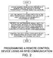
- FIG. 2is a flowchart of steps for programming a remote control device using RFID technology.
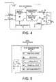
- FIG. 3is a simplified block diagram of an RFID reader embedded in a remote control device, as well as an RFID transponder.
- FIG. 4is a simplified block diagram of the RFID reader module of FIG. 3 .
- FIG. 5is a simplified block diagram of the RFID transponder of FIG. 3 .
- FIG. 6is a schematic diagram of an embodiment of the system of FIG. 1 including an RFID transponder in a codeset card.
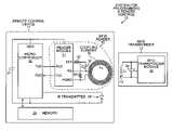
- FIG. 1shows a system 10 that uses a radio frequency identification (RFID) technology to program a remote control device 11 to control an electronic consumer device 12 .
- Electronic consumer device 12includes an RFID transponder 13 .
- RFID transponder 13may, for example, be embedded into, or attached to, the housing of electronic consumer device 12 .
- RFID transponder 13has a coupling element 14 , which is an inductor L T .
- electronic consumer device 12is a digital video disc (DVD) player.
- DVDdigital video disc
- remote control device 11also controls the operation of various other electronic consumer devices.
- the other electronic consumer devices controlled by remote control device 11include, for example, a television set, a video cassette recorder, a stereo equalizer, a radio tuner, a set-top box for receiving programming via a satellite, and a set-top box for receiving programming via a cable.
- Remote control device 11includes an RFID reader 15 that includes a coupling element 16 .
- Remote control device 11controls DVD player 12 by transmitting operational signals containing codeset data from a first codeset.
- the codeset dataare associated with DVD player 12 .
- An operational signal 17contains codeset key data corresponding to a function of DVD player 12 , such as “play.”
- Other functions that remote control device 11 controlsinclude, for example, power on, volume up, volume down, mute, channel advance, channel back, cursor up, cursor down, cursor right, cursor left, menu, select, record, stop, forward, back and pause.
- Remote control device 11includes an IR transmitter 18 .
- Operational signal 17is transmitted in an infrared (IR) channel from IR transmitter 18 to an IR receiver 19 on DVD player 12 .
- IRinfrared
- remote control device 11has a radio frequency (RF) transmitter that transmits operational signal 17 over an RF channel to an RF receiver on electronic consumer device 12 .
- RFradio frequency
- remote control device 11Before remote control device 11 transmits operational signal 17 , however, remote control device 11 is programmed to generate codeset key data corresponding to the first codeset, which controls DVD player 12 .
- remote control device 11includes a memory. Codeset data for multiple codesets, including the first codeset, are stored in the memory. The codeset data for each codeset include codeset information, as well as tables of modulation, timing and framing protocols. Codeset information includes a protocol number of each particular codeset, key flags, codeset key data, a system code, and format and size information relating to the system code and key data.
- the protocol number for the first codesetwhich controls DVD player 12 , is a pointer that points to the protocol table that contains the modulation, timing and framing protocol used to modulate the key data and the system code onto operational signal 17 .
- the digital values of the system code and the key dataare modulated onto operational signal 17 using a modulation technique (for example, pulse width modulation) determined by the protocol table that is pointed to.
- a modulation techniquefor example, pulse width modulation
- remote control device 11is programmed to control DVD player 12 when remote control device 11 receives a programming signal 20 containing a designation of the first codeset, along with a one-digit device number.
- the designation of the first codesetis a three-digit decimal number.
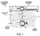
- FIG. 2is a flowchart illustrating steps 21 – 24 of a method by which system 10 programs a remote control device using radio frequency identification (RFID) technology. The steps of FIG. 2 will now be described in relation to the programming remote of remote control device 11 to transmit operational signal 17 containing codeset key data that controls a function of DVD player 12 , as shown in FIG. 1 .
- RFIDradio frequency identification
- a consumerplaces remote control device 11 in close proximity (for example, six centimeters) to the RFID reader 13 within electronic consumer device 12 and presses a program key on remote control device 11 .
- Pressing the program keycauses a frequency generator within remote control device 11 to generate an oscillating current in coupling element 16 .
- the oscillating currentmay, for example, oscillate at 125 kHz.
- the oscillating current in coupling element 16generates an alternating magnetic field 26 .
- Remote control device 11(including the frequency generator within it) is battery-powered and the energy of the alternating magnetic field 26 comes from the battery.
- coupling element 16is a coil of lacquered copper wire.
- the diameter of the coilis thirty-five mm, and the diameter of the copper wire is 0.223 mm. There are 85 turns in the coil.
- RFID transponder 13is a passive RFID transponder and is not connected to a battery or other power source. In this example, RFID transponder 13 is a circuit independent of the other circuitry of electronic consumer device 12 .
- FIG. 3is a simplified block diagram of remote control device 11 and RFID transponder 13 .
- Remote control device 11includes RFID reader 15 , IR transmitter 18 , a battery 27 , a microcontroller 28 and a memory 29 .
- IR transmitter 18is a light-emitting diode.
- Memory 29is an EEPROM memory.
- Battery 27provides a supply voltage of between two to five volts. In first step 21 , energy from battery 27 generates alternating magnetic field 26 and is conveyed from RFID reader 15 to RFID transponder 13 in DVD player 12 .
- RFID reader 15includes coupling element 16 , a capacitor 30 , a reader module 31 , a first resistor 32 and a second resistor 33 .
- Capacitor 30 and coupling element 16together form an LC circuit having a characteristic resonant frequency.
- the capacitance C R of reader capacitor 30is set such that alternating magnetic field 26 oscillates at 125 kHz ⁇ 4 kHz.
- the resistance of first resistor 32 and second resistor 33can be regulated in order to stabilize the LC circuit when it acts as an antenna.
- RFID transponder 13includes transponder coupling element 14 , a capacitor 34 and an RFID transponder module 35 .
- Capacitor 34 and transponder coupling element 14together form an LC circuit having a characteristic resonant frequency.
- the capacitance C T of transponder capacitor 34is set such that the LC circuit of RFID transponder 13 is tuned to about 125 kHz.
- FIG. 4shows reader module 31 in more detail.
- Reader module 31includes a microcontroller 36 , a transmitter portion 37 , a receiver portion 38 , EEPROM memory 39 , a serial interface input lead RxD 40 from microcontroller 28 , a serial interface output lead TxD 41 to microcontroller 28 , an antenna output lead Tx 1 42 , an antenna input lead Rx 43 , and an analog ground lead 44 .
- Serial interface input lead RxD 40 and serial interface output lead TxD 41can operate using RS232, RS422 or RS485 interface protocols.
- FIG. 5shows the circuitry of RFID transponder module 35 of RFID transponder 13 in more detail.
- RFID transponder module 35includes control logic 45 , a rectifier 46 , a modulator 47 , a demodulator 48 and EEPROM memory 49 .
- EEPROM memory 49has a 2048-bit capacity.
- a second step 22energy 25 conveyed from RFID reader 16 to RFID transponder 13 is used to power the circuitry of RFID transponder 13 .
- Rectifier 46 in RFID transponder module 35generates a rectified version of the alternating signal in coupling element 14 .
- Control logic 45then retrieves codeset data stored in EEPROM memory 49 .
- the codeset data stored in memory 49are a three-digit decimal number designating the particular codeset that controls DVD player 12 .
- Modulator 47modulates the codeset data using amplitude shift keying (ASK) modulation, and circuitry in RFID transponder 13 generates programming signal 20 containing the modulated codeset data.
- ASKamplitude shift keying
- RFID transponder 13In addition to capturing energy to power the circuitry of RFID transponder 13 , RFID transponder 13 also selectively draws energy from magnetic field 26 by regulating the impedance of its LC circuit. Programming signal 20 is used to control this selective drawing of energy (absorption modulation).
- RFID reader 15detects the selective drawing of energy such that programming signal 20 is received (step 23 ) onto the RFID reader 15 of remote control device 11 .
- RFID reader 15receives programming signal 20 by detecting a voltage drop on reader coupling element 16 when an amount of alternating magnetic field 26 is absorbed by transponder coupling element 14 .
- programming signal 20includes the designation of the first codeset. The designation of the first codeset is therefore communicated via absorption modulation from RFID transponder 13 to RFID reader 15 .
- codeset data for multiple codesetsare stored in memory 29 of remote control device 11 .
- Microcontroller 28activates the particular codeset stored in memory 29 that is indicated by the designation of the first codeset, thereby enabling remote control device 11 to control DVD player 12 .
- remote control device 11transmits operational signal 17 to DVD player 12 , causing DVD player 12 to perform a function associated with pressing one or more keys on remote control device 11 .
- Step 24may be initiated by the consumer's pressing of a key on remote control device 11 , wherein the pressing of the key causes operational signal 17 to be transmitted from IR transmitter 18 .
- Microcontroller 28modulates the codeset key data onto operational signal 17 that corresponds to the desired function of DVD player 12 , in this example “play.”
- codeset data for the first codesetare not initially stored in memory 29 of remote control device 11 .
- the entire first codesetis stored in memory 49 of RFID transponder module 35 .
- several other entire codesetscan also be stored in the 2048-bit/256-byte memory 49 of RFID transponder module 35 .
- the overall memory required to store multiple codesetscan be reduced by sharing common modulation protocols, as opposed to storing common protocols with each codeset.
- the total size of a table of codeset information plus the corresponding table of modulation, timing and framing protocolscan be less than one hundred bytes.
- the codeset information table and the protocol table for the first codesetoccupy about sixty bytes in memory 49 .
- modulator 47modulates the codeset information table and the protocol table for the first codeset onto programming signal 20 .
- RFID reader 15receives programming signal 20 , which in this case includes the entire first codeset.
- RFID reader 15receives codeset key data corresponding to various functions of DVD player 12 .
- remote control device 11transmits operational signal 17 containing codeset key data.
- the codeset key datacorrespond to one of the functions for which codeset key data were transmitted in programming signal 20 .
- FIG. 6illustrates a third example of the operation of system 10 .
- RFID transponder 13is contained in a codeset card 50 .
- the form of codeset card 50resembles RFID tags used as building access cards.
- up to four 60-byte codesetsare stored in the 256-byte memory 49 of RFID transponder module 35 of RFID transponder 13 .
- the codesetsare loaded into remote control device 11 by placing codeset card 50 in the vicinity of remote control device 11 and by pressing a programming key on remote control device 11 .
- Codeset card 50can be delivered to the consumer along with electronic consumer device 12 .
- codeset card 50is inserted into a packing box containing DVD player 12 . The cost of incorporating RFID transponder 13 into the hardware of DVD player 12 is thereby avoided.
- a consumercan obtain codeset card 50 from someone other than the manufacturer of electronic consumer device 12 .
- a consumer who wishes to avoid the hassle of programming remote control device 11 to control the various electronic consumer devices in the consumer's householdcan program the various devices by purchasing a codeset card for each of the devices.
- the consumerthen easily programs remote control device 11 by placing each of the cards near remote control device 11 , and loading the codesets from the cards into the remote control device 11 .
- the consumermay, for example, purchase codeset cards at an appliance store.
- a consumermight also wish to use system 10 to program remote control device 11 to control an electronic consumer device for which the operating manual has been lost and which therefore cannot be programmed in the originally intended manner.
- system 10 in the third exampleincludes a 256-byte memory 49 in RFID transponder 13
- other embodimentshave RFID transponders with more memory.
- codeset card 50By providing more memory, tens or even hundreds of codesets can be stored in the memory of codeset card 50 .
- local appliance storessell codeset cards containing dozens of codesets for the most popular electronic consumer devices used in the geographical area where the codeset cards are sold. All the energy necessary to communicate the codeset data back to the RFID reader may be imparted to the RFID transponder before the codeset data is communicated back. Alternatively, energy can be imparted to the RFID transponder at the same time that the RFID transponder is communicating codeset data back to the RFID reader.
- Codeset datacan be read out of an RFID transponder in a set of interrogations. Although a passive RFID transponder is described above, codeset data is communicated in other embodiments by active (powered) RFID transponders. Such active RFID transponders may be batter-powered, or may be powered by the power source of the electronic consumer device.
- RFID transpondersManufacturers of electronic consumer devices may not wish to include RFID transponders in their devices or even codeset cards along with their devices. In this situation, system 10 can nevertheless be used to program remote control devices.
- a television manufacturermay choose not to incorporate an RFID transponder containing a codeset designation or a complete codeset into it televisions.
- the television manufacturermay, however, embed an RFID transponder into a television or its packaging for its own purposes, such as to track the television during manufacturing or to assist in inventory control.
- the RFID transponderwould contain a serial number uniquely identifying the television within the universe of televisions made by the particular manufacturer. The serial number might not be unique with respect to all televisions on the market.
- remote control device 11includes cross-reference information that associates serial numbers with codeset numbers.
- RFID reader 15 in remote control device 11interrogates the manufacturer's RFID transponder in the television and reads back the serial number.
- Microcontroller 28 of remote control device 11uses the serial number to index a cross-reference table in memory 29 to lookup the particular codeset associated with the serial number.
- Information other than serial numbersmay also be used as inputs to the cross-reference table. The consumer may, for example, enter certain easy-to-enter information such as the brand of the television, and this information in combination with the serial number is used to determine the associated codeset.
- system 10can transfer energy and information using other mechanisms.
- system 10can employ backscatter coupling in which a small portion of an RF signal from RFID reader 15 is reflected by RFID transponder 13 back to RFID reader 15 . The reflected signal is modulated and encoded with codeset information.
- the RFID transpondercan be powered by a magnetic field leaking out of the power cord of electronic consumer device 12 . In this way, the RFID transponder is charged using energy from the 60 Hz wall current, as opposed to energy from battery 27 .
- the RFID transponderis attached to the power cord or to electronic consumer device 12 somewhere near the power cord.
- the RFID transponderconstantly absorbs energy from the alternating magnetic field that is associated with the alternating electric field of the 60 Hz wall current.
- the RFID transponderuses the energy to power circuitry that generates a programming signal containing a designation of a codeset or a complete codeset. Control logic in RFID transponder can be programmed to transmit bursts of the programming signal at regular intervals, for example, every five seconds, while RFID transponder is constantly absorbing energy.
- system 10is described above as employing amplitude shift keying (ASK), other types of modulation and data encoding can be used, such as frequency shift keying (PSK), phase shift keying (PSK), Manchester coding and biphase coding.
- PSKfrequency shift keying
- PSKphase shift keying
- Manchester codingand biphase coding.
- the coupling elements of system 10are described as being wire coils, system 10 can also employ other types of coupling elements.
- system 10can implement backscatter coupling using a linear antenna.
- coupling elements that are coilsneed be neither round nor wire.
- rectangular-shaped traces on a flexible filmcan form a coupling element.
- Energycan be transmitted to an RFID transponder on one frequency, and information can be transmitted back to the RFID reader on another frequency. Any RFID technology can be used to read back codeset data.
- RFID reader circuitrycan be integrated onto a general purpose microcontroller integrated circuit such that the remote control device does not include an RFID reader module that is separate from the microcontroller integrated circuit that performs key scanning and that drives the IR transmitter LED. Accordingly, various modifications, adaptations, and combinations of various features of the described embodiments can be practiced without departing from the scope of the invention as set forth in the claims.
Landscapes
- Engineering & Computer Science (AREA)
- Computer Networks & Wireless Communication (AREA)
- Signal Processing (AREA)
- Selective Calling Equipment (AREA)
Abstract
Description
Claims (11)
Priority Applications (1)
| Application Number | Priority Date | Filing Date | Title |
|---|---|---|---|
| US10/814,708US7116229B1 (en) | 2004-03-31 | 2004-03-31 | Programming a remote control device using RFID technology |
Applications Claiming Priority (1)
| Application Number | Priority Date | Filing Date | Title |
|---|---|---|---|
| US10/814,708US7116229B1 (en) | 2004-03-31 | 2004-03-31 | Programming a remote control device using RFID technology |
Publications (1)
| Publication Number | Publication Date |
|---|---|
| US7116229B1true US7116229B1 (en) | 2006-10-03 |
Family
ID=37037295
Family Applications (1)
| Application Number | Title | Priority Date | Filing Date |
|---|---|---|---|
| US10/814,708Expired - LifetimeUS7116229B1 (en) | 2004-03-31 | 2004-03-31 | Programming a remote control device using RFID technology |
Country Status (1)
| Country | Link |
|---|---|
| US (1) | US7116229B1 (en) |
Cited By (31)
| Publication number | Priority date | Publication date | Assignee | Title |
|---|---|---|---|---|
| US20060084409A1 (en)* | 2004-10-15 | 2006-04-20 | Muffaddal Ghadiali | Systems for and methods of programming a remote control |
| US20060192653A1 (en)* | 2005-02-18 | 2006-08-31 | Paul Atkinson | Device and method for selectively controlling the utility of an integrated circuit device |
| US20070176735A1 (en)* | 2003-05-28 | 2007-08-02 | Johnson Controls Technolgy Company | System and method for receiving data for training a trainable transmitter |
| US20080088474A1 (en)* | 2006-09-29 | 2008-04-17 | Sony Corporation | System and method for informing user how to use universal remote control |
| US20080094198A1 (en)* | 2006-10-20 | 2008-04-24 | Cub Elecparts Inc. | Setting method and system for a programmable universal tire pressure monitor |
| US20080136640A1 (en)* | 2006-12-07 | 2008-06-12 | Arnaud Lund | Method and system for controlling distant equipment |
| EP1959410A1 (en) | 2007-02-14 | 2008-08-20 | Vodafone Holding GmbH | Method for transmitting signals to a consumer electronics device and intermediate device for this transmission |
| US20080231492A1 (en)* | 2007-03-22 | 2008-09-25 | Robert Hardacker | System and method for application dependent universal remote control |
| US20080231762A1 (en)* | 2007-03-22 | 2008-09-25 | Sony Corporation | System and method for application dependent universal remote control |
| WO2008144785A1 (en)* | 2007-05-25 | 2008-12-04 | Fronius International Gmbh | Welding system and method for transmitting information and for influencing parameters of a welding system |
| US20090147150A1 (en)* | 2007-12-07 | 2009-06-11 | Sony Corporation | Remote control apparatus and communication system |
| US20100100310A1 (en)* | 2006-12-20 | 2010-04-22 | Johnson Controls Technology Company | System and method for providing route calculation and information to a vehicle |
| US20100097239A1 (en)* | 2007-01-23 | 2010-04-22 | Campbell Douglas C | Mobile device gateway systems and methods |
| US20100144284A1 (en)* | 2008-12-04 | 2010-06-10 | Johnson Controls Technology Company | System and method for configuring a wireless control system of a vehicle using induction field communication |
| US20100182160A1 (en)* | 2009-01-21 | 2010-07-22 | Ming-Wei Lu | Remote control with passive RFID tag and Zigbee arrangement |
| US20100245113A1 (en)* | 2009-03-25 | 2010-09-30 | At&T Intellectual Property I, L.P. | System and method for tracking a controller |
| US20110099590A1 (en)* | 2009-10-26 | 2011-04-28 | Lg Electronics Inc. | Digital broadcasting system and method of processing data in digital broadcasting system |
| US20120075074A1 (en)* | 2009-03-23 | 2012-03-29 | Satyatek Sa | System and method for reading one or more rfid tags in a metal cassette with an anticollision protocol |
| US8189120B2 (en) | 2009-02-04 | 2012-05-29 | Sony Corporation | Non-programmable universal remote system and method |
| US20120154195A1 (en)* | 2010-12-17 | 2012-06-21 | Sony Ericsson Mobile Communications Ab | System and method for remote controlled device selection |
| US20120242455A1 (en)* | 2011-03-25 | 2012-09-27 | Echostar Technologies L.L.C. | Apparatus, systems and methods for pairing a controlled device with an rf remote control using an rfid tag |
| US20130024542A1 (en)* | 2011-07-20 | 2013-01-24 | Rockwell Automation Technologies, Inc. | Software, systems, and methods for mobile visualization of industrial automation environments |
| US8447598B2 (en) | 2007-12-05 | 2013-05-21 | Johnson Controls Technology Company | Vehicle user interface systems and methods |
| US8634033B2 (en) | 2006-12-20 | 2014-01-21 | Johnson Controls Technology Company | Remote display reproduction system and method |
| US20140184385A1 (en)* | 2012-12-31 | 2014-07-03 | Dell Products, Lp | Pairing Remote Controller to Display Device |
| US20140247178A1 (en)* | 2006-02-21 | 2014-09-04 | Universal Electronics Inc. | Codeset communication format and related methods and structures |
| WO2014206645A1 (en)* | 2013-06-25 | 2014-12-31 | Wolfgang Brendel | Radio control system for controlling machines |
| US20150048928A1 (en)* | 2013-06-21 | 2015-02-19 | X-Card Holdings, Llc | Electronic credential signal activation systems and methods |
| US20150057841A1 (en)* | 2013-08-23 | 2015-02-26 | Hung-Wang Hsu | Motion sensing remote control device |
| US20180375965A1 (en)* | 2017-06-21 | 2018-12-27 | The Chamberlain Group, Inc. | Packaged Product Configuration |
| US20220103428A1 (en)* | 2017-07-11 | 2022-03-31 | Roku, Inc. | Automatic determination of display device functionality |
Citations (8)
| Publication number | Priority date | Publication date | Assignee | Title |
|---|---|---|---|---|
| US6020881A (en)* | 1993-05-24 | 2000-02-01 | Sun Microsystems | Graphical user interface with method and apparatus for interfacing to remote devices |
| US6167464A (en)* | 1998-09-23 | 2000-12-26 | Rockwell Technologies, Llc | Mobile human/machine interface for use with industrial control systems for controlling the operation of process executed on spatially separate machines |
| US6225938B1 (en)* | 1999-01-14 | 2001-05-01 | Universal Electronics Inc. | Universal remote control system with bar code setup |
| US6392544B1 (en)* | 2000-09-25 | 2002-05-21 | Motorola, Inc. | Method and apparatus for selectively activating radio frequency identification tags that are in close proximity |
| US6531964B1 (en) | 1999-02-25 | 2003-03-11 | Motorola, Inc. | Passive remote control system |
| US20040070491A1 (en)* | 1998-07-23 | 2004-04-15 | Universal Electronics Inc. | System and method for setting up a universal remote control |
| US7005979B2 (en)* | 2003-06-25 | 2006-02-28 | Universal Electronics Inc. | System and method for monitoring remote control transmissions |
| US7046161B2 (en)* | 1999-06-16 | 2006-05-16 | Universal Electronics Inc. | System and method for automatically setting up a universal remote control |
- 2004
- 2004-03-31USUS10/814,708patent/US7116229B1/ennot_activeExpired - Lifetime
Patent Citations (8)
| Publication number | Priority date | Publication date | Assignee | Title |
|---|---|---|---|---|
| US6020881A (en)* | 1993-05-24 | 2000-02-01 | Sun Microsystems | Graphical user interface with method and apparatus for interfacing to remote devices |
| US20040070491A1 (en)* | 1998-07-23 | 2004-04-15 | Universal Electronics Inc. | System and method for setting up a universal remote control |
| US6167464A (en)* | 1998-09-23 | 2000-12-26 | Rockwell Technologies, Llc | Mobile human/machine interface for use with industrial control systems for controlling the operation of process executed on spatially separate machines |
| US6225938B1 (en)* | 1999-01-14 | 2001-05-01 | Universal Electronics Inc. | Universal remote control system with bar code setup |
| US6531964B1 (en) | 1999-02-25 | 2003-03-11 | Motorola, Inc. | Passive remote control system |
| US7046161B2 (en)* | 1999-06-16 | 2006-05-16 | Universal Electronics Inc. | System and method for automatically setting up a universal remote control |
| US6392544B1 (en)* | 2000-09-25 | 2002-05-21 | Motorola, Inc. | Method and apparatus for selectively activating radio frequency identification tags that are in close proximity |
| US7005979B2 (en)* | 2003-06-25 | 2006-02-28 | Universal Electronics Inc. | System and method for monitoring remote control transmissions |
Non-Patent Citations (4)
| Title |
|---|
| C. Aquino, J. Linderman and T. Turman, "Bravo TV (Base, remote, Active Viewer Output)," 3 pages downloaded from Internet on Mar. 30, 2004 from http://coweb.cc.gatech.edu:8080/lcc6113b/40. |
| Data sheet entitled "HTCM400 HITAG core module hardware," by Philips Semiconductors, dated Oct. 4, 2001, 24 pages. |
| Eero Kytö, "Radio Frequency Identification Tags," 10 pages downloaded from Internet on Mar. 30, 2004 from http://mit.tut.fi/7504020/Materiaalit/Microsensors2002/. |
| Product specification entitled "HITAG 1 stick transponder HT1DC20S30," by Philips Semiconductors, dated Sep. 24, 2001, 7 pages. |
Cited By (62)
| Publication number | Priority date | Publication date | Assignee | Title |
|---|---|---|---|---|
| US20070176735A1 (en)* | 2003-05-28 | 2007-08-02 | Johnson Controls Technolgy Company | System and method for receiving data for training a trainable transmitter |
| US8330569B2 (en) | 2003-05-28 | 2012-12-11 | Johnson Controls Technology Company | System and method for receiving data for training a trainable transmitter |
| US20060084409A1 (en)* | 2004-10-15 | 2006-04-20 | Muffaddal Ghadiali | Systems for and methods of programming a remote control |
| US20060192653A1 (en)* | 2005-02-18 | 2006-08-31 | Paul Atkinson | Device and method for selectively controlling the utility of an integrated circuit device |
| US11961391B2 (en) | 2006-02-21 | 2024-04-16 | Universal Electronics Inc. | Codeset communication format and related methods and structures |
| US11657703B2 (en) | 2006-02-21 | 2023-05-23 | Universal Electronics Inc. | Codeset communication format and related methods and structures |
| US20140247178A1 (en)* | 2006-02-21 | 2014-09-04 | Universal Electronics Inc. | Codeset communication format and related methods and structures |
| US9582996B2 (en)* | 2006-02-21 | 2017-02-28 | Universal Electronics Inc. | Codeset communication format and related methods and structures |
| US20080088474A1 (en)* | 2006-09-29 | 2008-04-17 | Sony Corporation | System and method for informing user how to use universal remote control |
| US7952467B2 (en)* | 2006-09-29 | 2011-05-31 | Sony Corporation | System and method for informing user how to use universal remote control |
| US20080094198A1 (en)* | 2006-10-20 | 2008-04-24 | Cub Elecparts Inc. | Setting method and system for a programmable universal tire pressure monitor |
| US8115596B2 (en)* | 2006-12-07 | 2012-02-14 | Intermational Business Machines Corporation | Method and system for controlling distant equipment |
| US20080136640A1 (en)* | 2006-12-07 | 2008-06-12 | Arnaud Lund | Method and system for controlling distant equipment |
| US20100100310A1 (en)* | 2006-12-20 | 2010-04-22 | Johnson Controls Technology Company | System and method for providing route calculation and information to a vehicle |
| US8634033B2 (en) | 2006-12-20 | 2014-01-21 | Johnson Controls Technology Company | Remote display reproduction system and method |
| US9430945B2 (en) | 2006-12-20 | 2016-08-30 | Johnson Controls Technology Company | System and method for providing route calculation and information to a vehicle |
| US9587958B2 (en) | 2007-01-23 | 2017-03-07 | Visteon Global Technologies, Inc. | Mobile device gateway systems and methods |
| US20100097239A1 (en)* | 2007-01-23 | 2010-04-22 | Campbell Douglas C | Mobile device gateway systems and methods |
| EP1959410A1 (en) | 2007-02-14 | 2008-08-20 | Vodafone Holding GmbH | Method for transmitting signals to a consumer electronics device and intermediate device for this transmission |
| US20080231492A1 (en)* | 2007-03-22 | 2008-09-25 | Robert Hardacker | System and method for application dependent universal remote control |
| US20080231762A1 (en)* | 2007-03-22 | 2008-09-25 | Sony Corporation | System and method for application dependent universal remote control |
| WO2008144785A1 (en)* | 2007-05-25 | 2008-12-04 | Fronius International Gmbh | Welding system and method for transmitting information and for influencing parameters of a welding system |
| US8843066B2 (en) | 2007-12-05 | 2014-09-23 | Gentex Corporation | System and method for configuring a wireless control system of a vehicle using induction field communication |
| US8447598B2 (en) | 2007-12-05 | 2013-05-21 | Johnson Controls Technology Company | Vehicle user interface systems and methods |
| US20090147150A1 (en)* | 2007-12-07 | 2009-06-11 | Sony Corporation | Remote control apparatus and communication system |
| TWI381335B (en)* | 2007-12-07 | 2013-01-01 | Sony Corp | Remote control apparatus and communication system |
| US8736428B2 (en)* | 2007-12-07 | 2014-05-27 | Sony Corporation | Remote control apparatus and communication system |
| US10045183B2 (en) | 2008-12-04 | 2018-08-07 | Gentex Corporation | System and method for configuring a wireless control system of a vehicle |
| US9324230B2 (en)* | 2008-12-04 | 2016-04-26 | Gentex Corporation | System and method for configuring a wireless control system of a vehicle using induction field communication |
| WO2010065408A3 (en)* | 2008-12-04 | 2010-07-29 | Johnson Controls Technology Company | System and method for configuring a wireless control system of a vehicle using induction field communication |
| US20100144284A1 (en)* | 2008-12-04 | 2010-06-10 | Johnson Controls Technology Company | System and method for configuring a wireless control system of a vehicle using induction field communication |
| US20100182160A1 (en)* | 2009-01-21 | 2010-07-22 | Ming-Wei Lu | Remote control with passive RFID tag and Zigbee arrangement |
| US8189120B2 (en) | 2009-02-04 | 2012-05-29 | Sony Corporation | Non-programmable universal remote system and method |
| US20120075074A1 (en)* | 2009-03-23 | 2012-03-29 | Satyatek Sa | System and method for reading one or more rfid tags in a metal cassette with an anticollision protocol |
| US9727757B2 (en)* | 2009-03-23 | 2017-08-08 | Satyatek Sa | System and method for reading one or more RFID tags in a metal cassette with an anticollision protocol |
| US8274381B2 (en)* | 2009-03-25 | 2012-09-25 | At&T Intellectual Property I, L.P. | System and method for tracking a controller |
| US8482407B2 (en) | 2009-03-25 | 2013-07-09 | At&T Intellectual Property I, Lp | System and method for tracking a controller |
| US8742923B2 (en) | 2009-03-25 | 2014-06-03 | At&T Intellectual Property I, Lp | System and method for tracking a controller |
| US20100245113A1 (en)* | 2009-03-25 | 2010-09-30 | At&T Intellectual Property I, L.P. | System and method for tracking a controller |
| US8250612B2 (en)* | 2009-10-26 | 2012-08-21 | Lg Electronics Inc. | Digital broadcasting system and method of processing data in digital broadcasting system |
| US20110099590A1 (en)* | 2009-10-26 | 2011-04-28 | Lg Electronics Inc. | Digital broadcasting system and method of processing data in digital broadcasting system |
| US8963694B2 (en)* | 2010-12-17 | 2015-02-24 | Sony Corporation | System and method for remote controlled device selection based on device position data and orientation data of a user |
| US20120154195A1 (en)* | 2010-12-17 | 2012-06-21 | Sony Ericsson Mobile Communications Ab | System and method for remote controlled device selection |
| US9252848B2 (en) | 2011-03-25 | 2016-02-02 | Echostar Technologies L.L.C. | Apparatus, systems and methods for pairing a controlled device with an RF remote control using an RFID tag |
| US20120242455A1 (en)* | 2011-03-25 | 2012-09-27 | Echostar Technologies L.L.C. | Apparatus, systems and methods for pairing a controlled device with an rf remote control using an rfid tag |
| US8525651B2 (en)* | 2011-03-25 | 2013-09-03 | Echostar Technologies L.L.C. | Apparatus, systems and methods for pairing a controlled device with an RF remote control using an RFID tag |
| US20130024542A1 (en)* | 2011-07-20 | 2013-01-24 | Rockwell Automation Technologies, Inc. | Software, systems, and methods for mobile visualization of industrial automation environments |
| US9535415B2 (en)* | 2011-07-20 | 2017-01-03 | Rockwell Automation Technologies, Inc. | Software, systems, and methods for mobile visualization of industrial automation environments |
| US9019072B2 (en)* | 2012-12-31 | 2015-04-28 | Dell Products, Lp | Pairing remote controller to display device |
| US20140184385A1 (en)* | 2012-12-31 | 2014-07-03 | Dell Products, Lp | Pairing Remote Controller to Display Device |
| US12260695B2 (en) | 2013-06-21 | 2025-03-25 | X-Card Holdings, Llc | Electronic credential signal activation systems and methods |
| US9865105B2 (en)* | 2013-06-21 | 2018-01-09 | X-Card Holdings, Llc | Electronic credential signal activation systems and methods |
| US20150048928A1 (en)* | 2013-06-21 | 2015-02-19 | X-Card Holdings, Llc | Electronic credential signal activation systems and methods |
| US10255734B2 (en)* | 2013-06-21 | 2019-04-09 | X-Card Holdings, Llc | Electronic credential signal activation systems and methods |
| US10964146B2 (en) | 2013-06-21 | 2021-03-30 | X-Card Holdings, Llc | Electronic credential signal activation systems and methods |
| US11734979B2 (en) | 2013-06-21 | 2023-08-22 | X-Card Holdings, Llc | Electronic credential signal activation systems and methods |
| US11417162B2 (en) | 2013-06-21 | 2022-08-16 | X-Card Holdings, Llc | Electronic credential signal activation systems and methods |
| WO2014206645A1 (en)* | 2013-06-25 | 2014-12-31 | Wolfgang Brendel | Radio control system for controlling machines |
| US9486712B2 (en)* | 2013-08-23 | 2016-11-08 | Hung-Wang Hsu | Motion sensing remote control device |
| US20150057841A1 (en)* | 2013-08-23 | 2015-02-26 | Hung-Wang Hsu | Motion sensing remote control device |
| US20180375965A1 (en)* | 2017-06-21 | 2018-12-27 | The Chamberlain Group, Inc. | Packaged Product Configuration |
| US20220103428A1 (en)* | 2017-07-11 | 2022-03-31 | Roku, Inc. | Automatic determination of display device functionality |
Similar Documents
| Publication | Publication Date | Title |
|---|---|---|
| US7116229B1 (en) | Programming a remote control device using RFID technology | |
| US6531964B1 (en) | Passive remote control system | |
| US5218343A (en) | Portable field-programmable detection microchip | |
| US9646239B2 (en) | Combination full-duplex and half-duplex electronic identification tag | |
| US9412261B2 (en) | System and method for setting up a universal remote control | |
| US20180374340A1 (en) | Relaying key code signals through a remote control device | |
| EP0917767B1 (en) | A method for remotely controlling a plurality of apparatus using a single remote control device | |
| JPH0671344B2 (en) | How to communicate between the transceiver and the transponder located on the tool | |
| US8269608B2 (en) | Device and method of coupling a processor to an RFID tag | |
| US20050151886A1 (en) | Remote controller | |
| US6650247B1 (en) | System and method for configuring a home appliance communications network | |
| IL100451A (en) | Non-contact data communications system | |
| US5822098A (en) | Device and method of communication by infrared radiation between a user and a remotely controllable apparatus | |
| EP3545469B1 (en) | Method and apparatus for passive remote control | |
| EP0867078A1 (en) | Apparatus for bidirectional data and unidirectional power transmission between master and slave units using inductive coupling | |
| US20100013605A1 (en) | Data carrier and data carrier system | |
| US20090314830A1 (en) | Data carrier and data carrier system | |
| JP2006054757A (en) | Information communication system by rfid tag with sub communication interface | |
| JPH09135925A (en) | Golf club and grip, shaft, and head of the same |
Legal Events
| Date | Code | Title | Description |
|---|---|---|---|
| AS | Assignment | Owner name:ZILOG, INC., CALIFORNIA Free format text:ASSIGNMENT OF ASSIGNORS INTEREST;ASSIGNOR:MIRAMONTES, OSCAR C.;REEL/FRAME:015174/0824 Effective date:20040331 | |
| STCF | Information on status: patent grant | Free format text:PATENTED CASE | |
| FEPP | Fee payment procedure | Free format text:PAYER NUMBER DE-ASSIGNED (ORIGINAL EVENT CODE: RMPN); ENTITY STATUS OF PATENT OWNER: LARGE ENTITY Free format text:PAYOR NUMBER ASSIGNED (ORIGINAL EVENT CODE: ASPN); ENTITY STATUS OF PATENT OWNER: LARGE ENTITY | |
| AS | Assignment | Owner name:UEI CAYMAN INC., CALIFORNIA Free format text:ASSIGNMENT OF ASSIGNORS INTEREST;ASSIGNORS:ZILOG, INC.;ZILOG INTERNATIONAL, LTD.;REEL/FRAME:022343/0395 Effective date:20090218 Owner name:UEI CAYMAN INC.,CALIFORNIA Free format text:ASSIGNMENT OF ASSIGNORS INTEREST;ASSIGNORS:ZILOG, INC.;ZILOG INTERNATIONAL, LTD.;REEL/FRAME:022343/0395 Effective date:20090218 | |
| FPAY | Fee payment | Year of fee payment:4 | |
| FPAY | Fee payment | Year of fee payment:8 | |
| AS | Assignment | Owner name:C.G. DEVELOPMENT LIMITED, HONG KONG Free format text:ASSIGNMENT OF ASSIGNORS INTEREST;ASSIGNOR:UEI CAYMAN INC.;REEL/FRAME:038402/0250 Effective date:20110930 | |
| AS | Assignment | Owner name:UNIVERSAL ELECTRONICS INC., CALIFORNIA Free format text:ASSIGNMENT OF ASSIGNORS INTEREST;ASSIGNORS:C.G. DEVELOPMENT LIMITED;UEI CAYMAN INC.;REEL/FRAME:038416/0581 Effective date:20160427 | |
| MAFP | Maintenance fee payment | Free format text:PAYMENT OF MAINTENANCE FEE, 12TH YEAR, LARGE ENTITY (ORIGINAL EVENT CODE: M1553) Year of fee payment:12 |