US7116200B2 - Inductive coil assembly - Google Patents
Inductive coil assemblyDownload PDFInfo
- Publication number
- US7116200B2 US7116200B2US11/115,855US11585505AUS7116200B2US 7116200 B2US7116200 B2US 7116200B2US 11585505 AUS11585505 AUS 11585505AUS 7116200 B2US7116200 B2US 7116200B2
- Authority
- US
- United States
- Prior art keywords
- bobbin
- axis
- inductive
- coils
- coil assembly
- Prior art date
- Legal status (The legal status is an assumption and is not a legal conclusion. Google has not performed a legal analysis and makes no representation as to the accuracy of the status listed.)
- Expired - Lifetime
Links
- 230000001939inductive effectEffects0.000titleclaimsabstractdescription68
- 238000004891communicationMethods0.000abstractdescription32
- 238000012546transferMethods0.000abstractdescription9
- 230000008878couplingEffects0.000abstractdescription4
- 238000010168coupling processMethods0.000abstractdescription4
- 238000005859coupling reactionMethods0.000abstractdescription4
- 239000003990capacitorSubstances0.000description10
- 238000004519manufacturing processMethods0.000description5
- 238000013461designMethods0.000description4
- 238000010586diagramMethods0.000description4
- 238000004804windingMethods0.000description3
- 238000010276constructionMethods0.000description2
- 230000004907fluxEffects0.000description2
- 230000006870functionEffects0.000description2
- 238000000034methodMethods0.000description2
- 238000000465mouldingMethods0.000description2
- 239000000853adhesiveSubstances0.000description1
- 230000001070adhesive effectEffects0.000description1
- 230000004075alterationEffects0.000description1
- 238000013459approachMethods0.000description1
- 230000003750conditioning effectEffects0.000description1
- 230000001419dependent effectEffects0.000description1
- 230000005611electricityEffects0.000description1
- 238000001914filtrationMethods0.000description1
- 238000002955isolationMethods0.000description1
- 239000000463materialSubstances0.000description1
- 230000013011matingEffects0.000description1
- 230000008569processEffects0.000description1
- 230000035939shockEffects0.000description1
- 230000009131signaling functionEffects0.000description1
Images


Classifications
- H—ELECTRICITY
- H01—ELECTRIC ELEMENTS
- H01F—MAGNETS; INDUCTANCES; TRANSFORMERS; SELECTION OF MATERIALS FOR THEIR MAGNETIC PROPERTIES
- H01F27/00—Details of transformers or inductances, in general
- H01F27/28—Coils; Windings; Conductive connections
- A—HUMAN NECESSITIES
- A61—MEDICAL OR VETERINARY SCIENCE; HYGIENE
- A61L—METHODS OR APPARATUS FOR STERILISING MATERIALS OR OBJECTS IN GENERAL; DISINFECTION, STERILISATION OR DEODORISATION OF AIR; CHEMICAL ASPECTS OF BANDAGES, DRESSINGS, ABSORBENT PADS OR SURGICAL ARTICLES; MATERIALS FOR BANDAGES, DRESSINGS, ABSORBENT PADS OR SURGICAL ARTICLES
- A61L2/00—Methods or apparatus for disinfecting or sterilising materials or objects other than foodstuffs or contact lenses; Accessories therefor
- A61L2/02—Methods or apparatus for disinfecting or sterilising materials or objects other than foodstuffs or contact lenses; Accessories therefor using physical phenomena
- A61L2/08—Radiation
- A61L2/10—Ultraviolet radiation
- C—CHEMISTRY; METALLURGY
- C02—TREATMENT OF WATER, WASTE WATER, SEWAGE, OR SLUDGE
- C02F—TREATMENT OF WATER, WASTE WATER, SEWAGE, OR SLUDGE
- C02F1/00—Treatment of water, waste water, or sewage
- C02F1/008—Control or steering systems not provided for elsewhere in subclass C02F
- C—CHEMISTRY; METALLURGY
- C02—TREATMENT OF WATER, WASTE WATER, SEWAGE, OR SLUDGE
- C02F—TREATMENT OF WATER, WASTE WATER, SEWAGE, OR SLUDGE
- C02F1/00—Treatment of water, waste water, or sewage
- C02F1/30—Treatment of water, waste water, or sewage by irradiation
- C02F1/32—Treatment of water, waste water, or sewage by irradiation with ultraviolet light
- C02F1/325—Irradiation devices or lamp constructions
- C—CHEMISTRY; METALLURGY
- C02—TREATMENT OF WATER, WASTE WATER, SEWAGE, OR SLUDGE
- C02F—TREATMENT OF WATER, WASTE WATER, SEWAGE, OR SLUDGE
- C02F9/00—Multistage treatment of water, waste water or sewage
- C02F9/20—Portable or detachable small-scale multistage treatment devices, e.g. point of use or laboratory water purification systems
- H—ELECTRICITY
- H01—ELECTRIC ELEMENTS
- H01F—MAGNETS; INDUCTANCES; TRANSFORMERS; SELECTION OF MATERIALS FOR THEIR MAGNETIC PROPERTIES
- H01F38/00—Adaptations of transformers or inductances for specific applications or functions
- H01F38/14—Inductive couplings
- H—ELECTRICITY
- H01—ELECTRIC ELEMENTS
- H01F—MAGNETS; INDUCTANCES; TRANSFORMERS; SELECTION OF MATERIALS FOR THEIR MAGNETIC PROPERTIES
- H01F5/00—Coils
- H01F5/02—Coils wound on non-magnetic supports, e.g. formers
- H—ELECTRICITY
- H02—GENERATION; CONVERSION OR DISTRIBUTION OF ELECTRIC POWER
- H02J—CIRCUIT ARRANGEMENTS OR SYSTEMS FOR SUPPLYING OR DISTRIBUTING ELECTRIC POWER; SYSTEMS FOR STORING ELECTRIC ENERGY
- H02J50/00—Circuit arrangements or systems for wireless supply or distribution of electric power
- H02J50/005—Mechanical details of housing or structure aiming to accommodate the power transfer means, e.g. mechanical integration of coils, antennas or transducers into emitting or receiving devices
- H—ELECTRICITY
- H02—GENERATION; CONVERSION OR DISTRIBUTION OF ELECTRIC POWER
- H02J—CIRCUIT ARRANGEMENTS OR SYSTEMS FOR SUPPLYING OR DISTRIBUTING ELECTRIC POWER; SYSTEMS FOR STORING ELECTRIC ENERGY
- H02J50/00—Circuit arrangements or systems for wireless supply or distribution of electric power
- H02J50/10—Circuit arrangements or systems for wireless supply or distribution of electric power using inductive coupling
- H02J50/12—Circuit arrangements or systems for wireless supply or distribution of electric power using inductive coupling of the resonant type
- H—ELECTRICITY
- H02—GENERATION; CONVERSION OR DISTRIBUTION OF ELECTRIC POWER
- H02J—CIRCUIT ARRANGEMENTS OR SYSTEMS FOR SUPPLYING OR DISTRIBUTING ELECTRIC POWER; SYSTEMS FOR STORING ELECTRIC ENERGY
- H02J50/00—Circuit arrangements or systems for wireless supply or distribution of electric power
- H02J50/40—Circuit arrangements or systems for wireless supply or distribution of electric power using two or more transmitting or receiving devices
- H02J50/402—Circuit arrangements or systems for wireless supply or distribution of electric power using two or more transmitting or receiving devices the two or more transmitting or the two or more receiving devices being integrated in the same unit, e.g. power mats with several coils or antennas with several sub-antennas
- H—ELECTRICITY
- H05—ELECTRIC TECHNIQUES NOT OTHERWISE PROVIDED FOR
- H05B—ELECTRIC HEATING; ELECTRIC LIGHT SOURCES NOT OTHERWISE PROVIDED FOR; CIRCUIT ARRANGEMENTS FOR ELECTRIC LIGHT SOURCES, IN GENERAL
- H05B39/00—Circuit arrangements or apparatus for operating incandescent light sources
- H—ELECTRICITY
- H05—ELECTRIC TECHNIQUES NOT OTHERWISE PROVIDED FOR
- H05B—ELECTRIC HEATING; ELECTRIC LIGHT SOURCES NOT OTHERWISE PROVIDED FOR; CIRCUIT ARRANGEMENTS FOR ELECTRIC LIGHT SOURCES, IN GENERAL
- H05B41/00—Circuit arrangements or apparatus for igniting or operating discharge lamps
- H05B41/14—Circuit arrangements
- H05B41/24—Circuit arrangements in which the lamp is fed by high frequency AC, or with separate oscillator frequency
- H—ELECTRICITY
- H05—ELECTRIC TECHNIQUES NOT OTHERWISE PROVIDED FOR
- H05B—ELECTRIC HEATING; ELECTRIC LIGHT SOURCES NOT OTHERWISE PROVIDED FOR; CIRCUIT ARRANGEMENTS FOR ELECTRIC LIGHT SOURCES, IN GENERAL
- H05B41/00—Circuit arrangements or apparatus for igniting or operating discharge lamps
- H05B41/14—Circuit arrangements
- H05B41/36—Controlling
- H—ELECTRICITY
- H05—ELECTRIC TECHNIQUES NOT OTHERWISE PROVIDED FOR
- H05B—ELECTRIC HEATING; ELECTRIC LIGHT SOURCES NOT OTHERWISE PROVIDED FOR; CIRCUIT ARRANGEMENTS FOR ELECTRIC LIGHT SOURCES, IN GENERAL
- H05B47/00—Circuit arrangements for operating light sources in general, i.e. where the type of light source is not relevant
- H05B47/20—Responsive to malfunctions or to light source life; for protection
- C—CHEMISTRY; METALLURGY
- C02—TREATMENT OF WATER, WASTE WATER, SEWAGE, OR SLUDGE
- C02F—TREATMENT OF WATER, WASTE WATER, SEWAGE, OR SLUDGE
- C02F1/00—Treatment of water, waste water, or sewage
- C02F1/001—Processes for the treatment of water whereby the filtration technique is of importance
- C—CHEMISTRY; METALLURGY
- C02—TREATMENT OF WATER, WASTE WATER, SEWAGE, OR SLUDGE
- C02F—TREATMENT OF WATER, WASTE WATER, SEWAGE, OR SLUDGE
- C02F2201/00—Apparatus for treatment of water, waste water or sewage
- C02F2201/32—Details relating to UV-irradiation devices
- C02F2201/322—Lamp arrangement
- C02F2201/3228—Units having reflectors, e.g. coatings, baffles, plates, mirrors
- C—CHEMISTRY; METALLURGY
- C02—TREATMENT OF WATER, WASTE WATER, SEWAGE, OR SLUDGE
- C02F—TREATMENT OF WATER, WASTE WATER, SEWAGE, OR SLUDGE
- C02F2201/00—Apparatus for treatment of water, waste water or sewage
- C02F2201/32—Details relating to UV-irradiation devices
- C02F2201/326—Lamp control systems
- C—CHEMISTRY; METALLURGY
- C02—TREATMENT OF WATER, WASTE WATER, SEWAGE, OR SLUDGE
- C02F—TREATMENT OF WATER, WASTE WATER, SEWAGE, OR SLUDGE
- C02F2209/00—Controlling or monitoring parameters in water treatment
- C02F2209/005—Processes using a programmable logic controller [PLC]
- C—CHEMISTRY; METALLURGY
- C02—TREATMENT OF WATER, WASTE WATER, SEWAGE, OR SLUDGE
- C02F—TREATMENT OF WATER, WASTE WATER, SEWAGE, OR SLUDGE
- C02F2209/00—Controlling or monitoring parameters in water treatment
- C02F2209/005—Processes using a programmable logic controller [PLC]
- C02F2209/008—Processes using a programmable logic controller [PLC] comprising telecommunication features, e.g. modems or antennas
- C—CHEMISTRY; METALLURGY
- C02—TREATMENT OF WATER, WASTE WATER, SEWAGE, OR SLUDGE
- C02F—TREATMENT OF WATER, WASTE WATER, SEWAGE, OR SLUDGE
- C02F2209/00—Controlling or monitoring parameters in water treatment
- C02F2209/40—Liquid flow rate
- H—ELECTRICITY
- H01—ELECTRIC ELEMENTS
- H01F—MAGNETS; INDUCTANCES; TRANSFORMERS; SELECTION OF MATERIALS FOR THEIR MAGNETIC PROPERTIES
- H01F5/00—Coils
- H01F5/02—Coils wound on non-magnetic supports, e.g. formers
- H01F2005/027—Coils wound on non-magnetic supports, e.g. formers wound on formers for receiving several coils with perpendicular winding axes, e.g. for antennae or inductive power transfer
- H—ELECTRICITY
- H01—ELECTRIC ELEMENTS
- H01F—MAGNETS; INDUCTANCES; TRANSFORMERS; SELECTION OF MATERIALS FOR THEIR MAGNETIC PROPERTIES
- H01F5/00—Coils
- H01F5/04—Arrangements of electric connections to coils, e.g. leads
- H01F2005/043—Arrangements of electric connections to coils, e.g. leads having multiple pin terminals, e.g. arranged in two parallel lines at both sides of the coil
- H—ELECTRICITY
- H01—ELECTRIC ELEMENTS
- H01F—MAGNETS; INDUCTANCES; TRANSFORMERS; SELECTION OF MATERIALS FOR THEIR MAGNETIC PROPERTIES
- H01F5/00—Coils
- H01F5/04—Arrangements of electric connections to coils, e.g. leads
- H01F2005/046—Details of formers and pin terminals related to mounting on printed circuits
Definitions
- the present inventionis a division of application U.S. application Ser. No. 10/689,224, filed Oct. 20, 2003, which is a continuation-in-part of U.S. patent application Ser. No. 10/357,932, entitled “Inductively Powered Apparatus,” which was filed on Feb. 4, 2003.
- the present inventionrelates to the inductive transfer of power and communications, and more particularly to methods and apparatus for receiving inductively transmitted power and communications.
- inductive power transferhas been known for many years.
- poweris wirelessly transferred from a primary coil (or simply “primary”) in a power supply circuit to a secondary coil (or simply “secondary”) in a secondary circuit.
- the secondary circuitis electrically coupled with a device, such as a lamp, a motor, a battery charger or any other device powered by electricity.
- the wireless connectionprovides a number of advantages over conventional hardwired connections.
- a wireless connectioncan reduce the chance of shock and can provide a relatively high level of electrical isolation between the power supply circuit and the secondary circuit.
- Inductive couplingscan also make it easier for a consumer to replace limited-life components. For example, in the context of lighting devices, an inductively powered lamp assembly can be easily replaced without the need to make direct electrical connections. This not only makes the process easier to perform, but also limits the risk of exposure to electric shock.
- inductive power transferhas, however, for the most part been limited to niche applications, such as for connections in wet environments.
- the limited use of inductive power transferhas been largely the result of power transfer efficiency concerns.
- To improve the efficiency of the inductive couplingit is conventional to carefully design the configuration and layout of the primary and secondary coils.
- the primary and the secondaryare conventionally disposed within closely mating components with minimal gap between the primary and the secondary.
- the primaryis often disposed within a base defining a central opening and the secondary is often disposed within a cylindrical component that fits closely within the central opening of the base.
- This and other conventional constructionsare design to provide close coaxial and radial alignment between the primary coil and the secondary coil.
- a deviceis provided with an inductive coil assembly having a plurality of secondary coils that are each arranged in a different orientation.
- the multiple coilspermit the device to efficiently receive power or communications or both when the device is disposed at different orientations with respect to the primary.
- the inductive coil assemblyincludes three coils that are arranged along the x, y and z axes of a standard Cartesian coordinate system. In this embodiment, efficient power and communications transfer is obtainable regardless of the orientation of the device within the primary.
- the inductive coil assemblyincludes a single set of coils to receive power and to send and receive communications.
- the power signalfunctions as a carrier signal for the communications.
- separate coilscan be provided for power and communication. For example, a first set of z, y and z coils can be provided to receive power and a second set of x, y and z coils can be provided to receive communications.
- the inductive coil assemblyincludes a one-piece bobbin that facilitates manufacture and assembly of the inductive coil assembly.
- the bobbinincludes a separate spool with winding guides along each of the three axes and is designed to permit molding without the need for slides, pins or other complex mold tools.
- the inductive coil assemblycan be used as a primary to transmit power or communication or both to a second.
- the inductive coil assembly with different coils at different orientationscan generate magnetic fields at different orientation and thereby provide sufficient inductive coupling when an inductive device with only a single secondary coil is at different orientations.
- an inductive devicemay include a secondary with two coils that are oriented at 90 degrees to one another. With this configuration, at least one of the two coils is likely to extend across the flux lines of the magnetic field and receive power from the primary.
- the number of separate coilsmay vary from application to application, for example, the inductive device may include 3, 4, 6 or 8 coils at different orientations to provide improved efficiency in a wide variety of orientations. By providing a sufficient number of coils at different orientations, the inductive device can be configured to receive power from the primary regardless of the orientation of the inductive device.
- the present inventionprovides a simple and inexpensive inductive coil assembly that improves the efficiency of inductive systems when precise primary/secondary alignment does not exist.
- the present inventionpermits power and communications to be transferred inductively in an environment where the position of the secondary within the primary may vary.
- the inductive coil assemblyis manufactured on a bobbin that provides winding guides along all three axes, yet is easily manufactured without complex slide, pins or other complex mold tools.
- FIG. 1 ais a perspective view of an inductive coil assembly in accordance with an embodiment of the present invention.
- FIG. 1 bis a top plan view of the inductive coil assembly.
- FIG. 1 cis a front plan view of the inductive coil assembly.
- FIG. 1 dis a side elevational view of the inductive coil assembly.
- FIG. 2is a perspective view of a bobbin in accordance with an embodiment of the present invention.
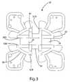
- FIG. 3is a top plan view of the bobbin.
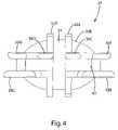
- FIG. 4is a front view of the bobbin.
- FIG. 5is a right side elevational view of the bobbin.
- FIG. 6is a perspective view of two mold pieces for use in molding the bobbin.
- FIG. 7is a plan view of the first mold piece.
- FIG. 8is a plan view of the second mold piece.
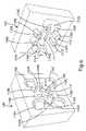
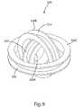
- FIG. 9is a perspective view of an alternative bobbin.
- FIG. 10is a perspective view of a second alternative bobbin.
- FIG. 11is a perspective view of a third alternative bobbin.
- FIGS. 12 a–dare perspective views of a fourth alternative bobbin showing the bobbin is different mounting position.
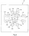
- FIGS. 13 a–care circuit diagrams of alternative multi-axis inductive coil assembly circuits for receiving power from an inductive source.
- FIG. 14is a circuit diagram of a multi-axis inductive coil assembly circuit for receiving communication from an inductive source.
- FIGS. 1 a–dAn inductive coil assembly 10 manufactured in accordance with an embodiment of the present invention is shown in FIGS. 1 a–d .
- the inductive coil assembly 10generally includes three separate coils 12 , 14 and 16 that are arranged at separate orientations with respect to one another.
- the separate coils 12 , 14 and 16may be electrically connected to a device through an inductive control circuit.
- the separate coils 12 , 14 and 16may be wrapped around a one-piece bobbin 20 that facilitates the manufacture and assembly of the present invention.
- the present inventionis described in connection with a three-coil embodiment, the number of coils may vary.
- the inductive coil assembly 10includes a bobbin 20 for supporting the various coils 12 , 14 and 16 .
- the bobbin 20is a one-piece structure that is specially designed for easy manufacture and easy assembly of the inductive coil assembly 10 .
- the bobbin 20is configured to support three separate coils 12 , 14 and 16 arranged substantially orthogonally with respect to one another. More specifically, the bobbin 20 accommodates three coils 12 , 14 and 16 , one oriented about each of the x, y and z axes of a Cartesian three-dimensional coordinate system.
- the bobbin 20also includes a pair of electrical pins 62 a–b , 64 a–b and 66 a–b for electrically connecting opposite ends of each coil to a circuit board (not shown).
- the bobbin 20may be designed to be molded with a two-piece mold requiring no moving slides, moving pins or other complex moving mold elements. As show in FIGS. 3 , 4 and 5 , this is achieved by the unique configuration of the bobbin 20 , which does not include any undercuts that would prevent removal of the molded part from the mold.
- FIG. 3shows a top view of the bobbin 20 , which is in a direction parallel to the direction in which the mold opens and closes.
- FIG. 4shows a front view the bobbin 20 , which is in a direction perpendicular to the direction in which the mold opens and closes.
- FIG. 5shows a side elevations view of the bobbin 20 , which like FIG.
- the bobbin 20generally defines three separate spools 22 , 24 and 26 , one for each of the three coils 12 , 14 and 16 .
- the first spool 22includes a core 28 and a pair of opposed guide walls 30 a–b that define a somewhat oval channel to receive wire.
- the core 28defines an opening 29 .
- the first coil 12is wrapped around the core 28 with the guide walls 30 a–b providing a wrapping guide and helping to retain the coil 12 .
- the second spool 24is defined by a second core 34 and a second pair of guide walls 32 a–b .
- the second core 34may be convex to provide a round surface for receiving the second coil 14 .
- the core 34can be partially defined by the outer surfaces of the guide walls 30 a–b of the first spool 22 .
- the second pair of guide walls 32 a–bextends perpendicularly to the guide walls 30 a–b of the first spool 22 .
- the second coil 14is wrapped around the second core 34 with the guide walls 32 a–b providing a wrapping guide and helping to retain the coil 14 .
- the third spool 26is defined by a third core 40 , inner guide segments 36 a–h and outer guide segments 38 a–d .
- the outer surfaces of the core 40may be convex to provide a curved surface for receiving the coil 16 .
- the core 40can be partially defined by the outer surfaces of the guide walls 32 a–b of the second spool 24 .
- the inner guide segments 36 a–hextend along a common plane to cooperatively define a first wiring guide for the third coil 16 .
- the outer guide segments 38 a–dextend along a common plane to cooperatively define a second wiring guide for the third coil 16 .
- the inner guide segments 36 a–hdo not overlap the outer guide segments 38 a–d along the direction of the axis of the spool 26 .
- FIG. 6is a perspective view showing the two mold pieces 100 and 102 in an open position.
- the mold pieces 100 and 102close together in a conventional manner to cooperatively define a mold cavity in the shape of the bobbin 20 .
- FIG. 6illustrates the mold contours, thereby showing how the two mold pieces 100 and 102 cooperate to define a single bobbin 20 three separate spools 22 , 24 and 26 without the need for moving slide, moving pins, moving cores or other moving mold components.
- the first mold piece 100forms the inner surfaces of the bobbin 20 and the second mold piece 102 forms the outer surfaces. Referring to FIGS.
- the first mold piece 100includes various contours that contribute to the shape of the first spool 22 , including generally arcuate recesses 104 a–b to cooperatively form the inner surfaces of the first core 28 , block 106 to form an opening in core 28 (primarily to save in weight and material), and generally arcuate channels 108 a–b to form the inner surfaces of the guide walls 30 a–b .
- the first mold piece 100defines generally arcuate recess 110 to form the inner surfaces of the second core 34 and generally arcuate channels 112 a–b to form the inner surfaces of the guide walls 32 a–b .
- the first mold piece 100defines channel segments 114 a–d to form the inner surfaces of the third core 34 , recesses 116 a–d to form the inner surfaces of outer guide segments 38 a–d , and recesses 118 a–d to receive protrusions 130 a–d of the second mold piece 102 and form the inner surfaces of inner guide segments 36 a–d .
- the first mold piece 100also defines a pair of recesses 120 a–b which receives protrusions 132 a–b and forms the inner surfaces of inner guide segments 36 e–h.
- the second mold piece 102defines the outer surfaces of the three spools 22 , 24 and 26 .
- the second mold piece 102defines a generally arcuate recess 122 which forms the outer surfaces of core 28 and generally arcuate channels 124 a–b which form the outer surfaces of guide walls 30 a–b .
- the second mold piece 102defines a generally arcuate recess 126 which forms the outer surface of core 34 and generally arcuate channels 128 a–b which form the outer surfaces of guide walls 32 a–b .
- the second mold pieceincludes a set of four protrusion 130 a–d that extend into recesses 118 a–d in the first mold piece 100 and a pair of protrusions 132 a–b that extend into recesses 120 a–b .
- Each protrusion 130 a–ddefines a recess 134 a–d to form the outer surfaces of inner guide segments 36 a–d .
- each protrusion 132 a–bdefines a pair of recesses 134 e–h to form the outer surfaces of inner guide segments 36 e–h.
- the inductive coil assemblymay include alternative constructions.
- an alternative inductive coil assemblymay include a separate, single-spool bobbin for each coil.
- the three-coil bobbin assembly 320 illustrated in FIG. 9includes three separate bobbins 320 a–c that have different diameters and are fitted one inside the other. Given that the power induced in a secondary coil is proportional to the diameter of the coil, the use of differently sized bobbins may result in an imbalance in the power supplied to each secondary coil.
- the inductive coil assembly 410may include three separate bobbins 420 a–c that are positioned adjacent to one another, rather than nested inside of one another.
- the inductive coil assemblymay include a spherical bobbin (not shown), with each coil being wrapped about the spherical bobbin at the desired location and in the desired orientation, for example, about the x, y and z axes.
- This embodimentreduces the differences in the diameters of the three secondaries, thereby improving the balance of the coils.
- the inductive coil assemblymay include three separate, unconnected bobbins that can be place at varied locations.
- the bobbinsmay be a simple annular spool or may include a unique shape that permits them to be easily mounted at different angles.
- An inductive coil with a unique multi-position bobbin 520is shown in FIGS. 11 and 12 a–d .
- This bobbin 520generally includes a single spool 522 , a pair of guide walls 524 a–b and a mounting arm 550 .
- the configuration of the various componentspermits the bobbin 520 to be mounted in various orientations, for example, to a circuit board.
- the mounting arm 550generally includes two arm segments 552 and 554 .
- the first arm segment 552includes a pair of rails 556 a–b .
- Rail 556 ais disposed at the end of the first arm segment 552 .
- the rails 556 a–bmay be triangular in cross section. For example, rail 556 a may extending at 45 degrees with respect to the axis of the spool.
- guide wall 524 amay terminate in a common plane with the mounting arm 550 , and more specifically with the end of the first arm segment 552 .
- the angle of this common planeis set at the desired mounting angle.
- the common planeextends at 45 degrees from the axis of the spool 522 .
- guide wall 524 amay be chamfered along the common plane, for example, at 45 degrees. In this way, the angled surface of rail 556 a and the chamfered edge of guide wall 524 a extend along the common plane to provide a firm structure for supporting the bobbin 520 at a 45 degree angle.
- the bobbin 520also includes two sets of electrical pins 540 a–b and 542 a–b that function as alternative electrical connections or alternative mounting pins or both depending on the orientation of the bobbin 520 .
- FIG. 12 ashows bobbin 520 mounted to a circuit board at a 45 degree angle.
- FIG. 12 bshows the bobbin 520 mounted to a circuit board in a vertical position extending partially through the board.
- FIG. 12 cshows the bobbin 520 mounted to a circuit board in a vertical position fully above (or below) the board.
- FIG. 12 dshows the bobbin 520 mounted to a circuit board in a horizontal position.
- the bobbinmay include two separately manufactured pieces that are assembled to form the complete bobbin.
- the bobbinmay be formed from two identical mold pieces, with the two mold pieces corresponding to the opposite halves of bobbin 20 when divided by a plane extending parallel to and mid-way between the inner and outer guide segments 36 a–h and 38 a–d , respectively. Because this alternative bobbin is formed in two separate pieces, the staggered inner and outer guide segments 36 a–h and 38 a–d , respectively, can be replaced by continuous guide walls. The continuous guide wall can be placed at the mold parting line to facilitate manufacture.
- the two bobbin piecesmay be separately molded and then welded, glued or otherwise intersecured to form the completed bobbin.
- the two bobbin piecesmay be held together by the coil windings.
- the two piecesmay be configured so that the first coil is wound in a direction that holds the two bobbin pieces together.
- the inductive coil assembly 10 of the present inventioncan be incorporated into essentially any inductively power device to improve power transfer in various orientations of the device within the magnetic field.
- a cell phone(not shown), personal digital assistant (not shown), notepad computer (not shown), digital music player (not shown) or electronic gaming device (not shown) can be provided with an inductively powered battery charger having a secondary with multiple coils, such as inductive coil assembly 10 .
- the cell phone, personal digital assistant, notepad computer, digital music player or electronic gaming devicecan be placed randomly within the magnetic field created by a primary coil without concern for its orientation because the inductive coil assembly 10 will be able to obtain sufficient power to charge the device in any orientation.
- FIGS. 13 a–cshow circuit diagrams for three embodiments of the inductive coil assembly.
- FIG. 13 aillustrates a circuit 680 that provides DC power from three separate coils 672 a–c . As shown, the three coils 672 a–c are connected in parallel to the load, a capacitor 674 a–c is connected in series between each coil 672 a–c and the load. In this embodiment, the value of each capacitor 674 a–c and each diode 676 a–c is selected to provide a resonant circuit for the load-side of the circuit. Accordingly, their values may be dependent on the characteristics of the load (not shown).
- This circuit 680combines the power induced within each of the coils using the capacitors to provide resonance with the load, and diodes 676 a–c rectifying the voltage output from circuit 680 .
- diodes 676 a–ccan be eliminated from the circuit 680 to provide AC power to the load.
- FIG. 13 billustrates a half wave rectifier circuit 680 ′ that provides DC power from three separate coils 672 a–c ′.
- the three coils 672 a–c ′are connected in parallel to the load through an arrangement of diodes 676 a–f ′ connected in series between each coil 672 a–c ′ and the load.
- the value of each diode 676 a–f ′is determined based primarily on the characteristics of the load.
- a capacitor 674 a–c ′is connected in series between one side of the coil 672 a–c ′ and the corresponding diodes 676 a–f ′.
- each capacitor 674 a–c ′is also determined based primarily on the characteristics of the load.
- This circuit 680 ′combines the power induced within each of the coils using the capacitors to provide resonance with the load, and diodes 676 a–f ′ rectifying the voltage output from the circuit 680 ′.
- FIG. 13 cillustrates a full wave rectifier circuit 680 ′′ that provides DC power from three separate coils 672 a–c ′′.
- the three coils 672 a–c ′′are connected in parallel to the load through an arrangement of diodes 676 a–l ′′ is connected in series between each coil 672 a–c ′′ and the load.
- the value of each diode 676 a–l ′′is determined based primarily on the characteristics of the load.
- a capacitor 674 a–c ′′is connected in series between one side of the coil 672 a–c ′′ and the corresponding diodes 676 a–c ′′ and diodes 676 j–l ′′.
- each capacitor 674 a–c ′′is determined based primarily on the characteristics of the load. All three of these circuits 680 , 680 ′ and 680 ′′ perform the function of providing DC power. Circuit 680 is likely the least expensive design, while circuit 680 ′′ provides the best control over the DC output, for example, circuit 680 ′′ likely provide less fluctuation in the output compared to the other two embodiments.
- the inductive coil assemblycan also be used to inductively transfer communications. In one embodiment, this can be achieved using an inductive coil assembly that is essentially identical to the inductive coil assembly 10 described above.
- the received communications signalsare carried on the power signal.
- a second set of coilsare used to provide communications. The second set of coils can be formed on the same bobbin used for the power coils, for example, by wrapping a separate communication coil on top of each power coil. The communications coils may require only one or two turns of wire. Alternatively, a second bobbin can be used for the communications coils.
- FIG. 14is a circuit diagram representing a conventional communications circuit for use in applications where the communications signals are separate from the power signals.
- This circuitenables the simple inductive exchange of communications between a primary and a secondary with a multi-axis inductive coil assembly.
- the coils 672 a–c ′′′are connected in series to the transceiver 690 a–b ′′′, which is represented by RX line 690 a ′′′ and TX line 690 b ′′′.
- the circuit 670 ′′′may include conventional filtering and conditioning components that limit current and increase the signal to noise ratio, thereby improving the performance of the circuit.
- the RX line 690 b ′′′may be include resistor 692 ′′′ and capacitor 694 ′′′ to reduce frequency spikes and noise to increase the signal to noise ratio.
- the circuit 670 ′′′may include resistor 696 ′′′ and capacitors 686 ′′′ and 688 ′′′′ to filter and condition the incoming and outgoing signals.
- This circuit 670 ′′′combines the communication signals induced within each of the coils 672 a–c ′′′ and applies them to RX line 690 b ′′′ or applies the signals returned from TX line 690 a ′′′ to the coils 672 a–c ′′′ to inductively transmit communication signals.
- the present inventionmay also be implemented using any of a wide variety of conventional circuits, including circuits in which the coils 672 a–c ′′′ are in a parallel relationship. As noted above, the present invention is also well suited for use in applications where the communications signals are carried by the power signals.
- the present inventionmay also be used as a multi-axis primary coil.
- the different coilsgenerate magnetic fields at different orientations.
- a single secondary coilis then capable of receiving power or communication or both at different orientations with respect to the primary, for example, as the secondary coil is sufficiently aligned with any one of the magnetic fields generated by the multi-coil inductive primary.
Landscapes
- Engineering & Computer Science (AREA)
- Power Engineering (AREA)
- Health & Medical Sciences (AREA)
- Life Sciences & Earth Sciences (AREA)
- Computer Networks & Wireless Communication (AREA)
- Hydrology & Water Resources (AREA)
- Environmental & Geological Engineering (AREA)
- Water Supply & Treatment (AREA)
- Chemical & Material Sciences (AREA)
- Organic Chemistry (AREA)
- Toxicology (AREA)
- Epidemiology (AREA)
- Animal Behavior & Ethology (AREA)
- General Health & Medical Sciences (AREA)
- Public Health (AREA)
- Veterinary Medicine (AREA)
- Clinical Laboratory Science (AREA)
- Coils Or Transformers For Communication (AREA)
- Near-Field Transmission Systems (AREA)
- Coils Of Transformers For General Uses (AREA)
Abstract
Description
The present invention is a division of application U.S. application Ser. No. 10/689,224, filed Oct. 20, 2003, which is a continuation-in-part of U.S. patent application Ser. No. 10/357,932, entitled “Inductively Powered Apparatus,” which was filed on Feb. 4, 2003.
The present invention relates to the inductive transfer of power and communications, and more particularly to methods and apparatus for receiving inductively transmitted power and communications.
The principles of inductive power transfer have been known for many years. As a result of mutual inductance, power is wirelessly transferred from a primary coil (or simply “primary”) in a power supply circuit to a secondary coil (or simply “secondary”) in a secondary circuit. The secondary circuit is electrically coupled with a device, such as a lamp, a motor, a battery charger or any other device powered by electricity. The wireless connection provides a number of advantages over conventional hardwired connections. A wireless connection can reduce the chance of shock and can provide a relatively high level of electrical isolation between the power supply circuit and the secondary circuit. Inductive couplings can also make it easier for a consumer to replace limited-life components. For example, in the context of lighting devices, an inductively powered lamp assembly can be easily replaced without the need to make direct electrical connections. This not only makes the process easier to perform, but also limits the risk of exposure to electric shock.
The use of inductive power transfer has, however, for the most part been limited to niche applications, such as for connections in wet environments. The limited use of inductive power transfer has been largely the result of power transfer efficiency concerns. To improve the efficiency of the inductive coupling, it is conventional to carefully design the configuration and layout of the primary and secondary coils. The primary and the secondary are conventionally disposed within closely mating components with minimal gap between the primary and the secondary. For example, the primary is often disposed within a base defining a central opening and the secondary is often disposed within a cylindrical component that fits closely within the central opening of the base. This and other conventional constructions are design to provide close coaxial and radial alignment between the primary coil and the secondary coil. Several specific examples of patents that reflect the conventional approach of providing a fixed, predetermined physical relationship between the primary and secondary coils include: U.S. Pat. No. 5,264,997 to Hutchisson et al, which discloses an inductive lamp with coaxial and closely interfitting primary and secondary coils; U.S. Pat. No. 5,536,979 to McEachern et al, which discloses an inductive charging device in which the device to be charged is fitted closely within a cradle to position the coils in a fixed, predetermined relationship; U.S. Pat. No. 5,949,155 to Tamura et al, which discloses a shaver with adjacent inductive coils set in a fixed relationship; U.S. Pat. No. 5,952,814 to Van Lerberghe, which discloses an inductive charger for a telephone wherein the physical relationship between the primary and secondary coils is fixed; and U.S. Pat. No. 6,028,413 to Brockman, which discloses a charging device having a mechanical guide for ensuring precise, predetermined alignment between the inductive coils. The conventional practice of providing precise alignment between the primary and secondary coil has placed significant limitation on the overall design and adaptability of inductively powered devices.
The aforementioned problems are overcome by the present invention wherein a device is provided with an inductive coil assembly having a plurality of secondary coils that are each arranged in a different orientation. The multiple coils permit the device to efficiently receive power or communications or both when the device is disposed at different orientations with respect to the primary.
In one embodiment, the inductive coil assembly includes three coils that are arranged along the x, y and z axes of a standard Cartesian coordinate system. In this embodiment, efficient power and communications transfer is obtainable regardless of the orientation of the device within the primary.
In another embodiment, the inductive coil assembly includes a single set of coils to receive power and to send and receive communications. In this embodiment, the power signal functions as a carrier signal for the communications. In an alternative embodiment, separate coils can be provided for power and communication. For example, a first set of z, y and z coils can be provided to receive power and a second set of x, y and z coils can be provided to receive communications.
In one embodiment, the inductive coil assembly includes a one-piece bobbin that facilitates manufacture and assembly of the inductive coil assembly. The bobbin includes a separate spool with winding guides along each of the three axes and is designed to permit molding without the need for slides, pins or other complex mold tools.
In another embodiment, the inductive coil assembly can be used as a primary to transmit power or communication or both to a second. The inductive coil assembly with different coils at different orientations can generate magnetic fields at different orientation and thereby provide sufficient inductive coupling when an inductive device with only a single secondary coil is at different orientations.
In applications where only a single coil is used, it is possible that a device randomly placed within a magnetic field will be located with the coil oriented substantially parallel to the magnetic field. In such situations, the secondary may not receive sufficient power to power the device from the primary. The use of multiple coils addresses this problem by providing a secondary coil arrangement that significantly increases the likelihood that at least one coil will at least substantially intersect the flux lines of the magnetic field generated by the primary. For example, an inductive device may include a secondary with two coils that are oriented at 90 degrees to one another. With this configuration, at least one of the two coils is likely to extend across the flux lines of the magnetic field and receive power from the primary. The number of separate coils may vary from application to application, for example, the inductive device may include 3, 4, 6 or 8 coils at different orientations to provide improved efficiency in a wide variety of orientations. By providing a sufficient number of coils at different orientations, the inductive device can be configured to receive power from the primary regardless of the orientation of the inductive device.
The present invention provides a simple and inexpensive inductive coil assembly that improves the efficiency of inductive systems when precise primary/secondary alignment does not exist. The present invention permits power and communications to be transferred inductively in an environment where the position of the secondary within the primary may vary. The inductive coil assembly is manufactured on a bobbin that provides winding guides along all three axes, yet is easily manufactured without complex slide, pins or other complex mold tools.
These and other objects, advantages, and features of the invention will be readily understood and appreciated by reference to the detailed description of the preferred embodiment and the drawings.
Aninductive coil assembly 10 manufactured in accordance with an embodiment of the present invention is shown inFIGS. 1 a–d. Theinductive coil assembly 10 generally includes threeseparate coils piece bobbin 20 that facilitates the manufacture and assembly of the present invention. Although the present invention is described in connection with a three-coil embodiment, the number of coils may vary.
As noted above, theinductive coil assembly 10 includes abobbin 20 for supporting thevarious coils bobbin 20 is a one-piece structure that is specially designed for easy manufacture and easy assembly of theinductive coil assembly 10. In the illustrated embodiment, thebobbin 20 is configured to support threeseparate coils bobbin 20 accommodates threecoils bobbin 20 also includes a pair of electrical pins62a–b,64a–band66a–bfor electrically connecting opposite ends of each coil to a circuit board (not shown).
To facilitate manufacture, thebobbin 20 may be designed to be molded with a two-piece mold requiring no moving slides, moving pins or other complex moving mold elements. As show inFIGS. 3 ,4 and5, this is achieved by the unique configuration of thebobbin 20, which does not include any undercuts that would prevent removal of the molded part from the mold.FIG. 3 shows a top view of thebobbin 20, which is in a direction parallel to the direction in which the mold opens and closes.FIG. 4 shows a front view thebobbin 20, which is in a direction perpendicular to the direction in which the mold opens and closes. Finally,FIG. 5 shows a side elevations view of thebobbin 20, which likeFIG. 4 is in a direction that is perpendicular to the direction in which the mold opens and closes. Referring now toFIG. 2 , thebobbin 20 generally defines threeseparate spools coils first spool 22 includes acore 28 and a pair of opposed guide walls30a–bthat define a somewhat oval channel to receive wire. Thecore 28 defines anopening 29. Thefirst coil 12 is wrapped around thecore 28 with the guide walls30a–bproviding a wrapping guide and helping to retain thecoil 12. Thesecond spool 24 is defined by asecond core 34 and a second pair of guide walls32a–b. Thesecond core 34 may be convex to provide a round surface for receiving thesecond coil 14. Alternatively, the core34 can be partially defined by the outer surfaces of the guide walls30a–bof thefirst spool 22. The second pair of guide walls32a–bextends perpendicularly to the guide walls30a–bof thefirst spool 22. Thesecond coil 14 is wrapped around thesecond core 34 with the guide walls32a–bproviding a wrapping guide and helping to retain thecoil 14. Thethird spool 26 is defined by athird core 40, inner guide segments36a–hand outer guide segments38a–d. The outer surfaces of the core40 may be convex to provide a curved surface for receiving thecoil 16. Alternatively, the core40 can be partially defined by the outer surfaces of the guide walls32a–bof thesecond spool 24. The inner guide segments36a–hextend along a common plane to cooperatively define a first wiring guide for thethird coil 16. Similarly, the outer guide segments38a–dextend along a common plane to cooperatively define a second wiring guide for thethird coil 16. As can be seen, the inner guide segments36a–hdo not overlap the outer guide segments38a–dalong the direction of the axis of thespool 26.
Thesecond mold piece 102 defines the outer surfaces of the threespools spool 22, thesecond mold piece 102 defines a generallyarcuate recess 122 which forms the outer surfaces ofcore 28 and generally arcuate channels124a–bwhich form the outer surfaces of guide walls30a–b. With regard tospool 24, thesecond mold piece 102 defines a generally arcuate recess126 which forms the outer surface ofcore 34 and generally arcuate channels128a–bwhich form the outer surfaces of guide walls32a–b. With regard tospool 26, the second mold piece includes a set of four protrusion130a–dthat extend into recesses118a–din thefirst mold piece 100 and a pair of protrusions132a–bthat extend into recesses120a–b. Each protrusion130a–ddefines a recess134a–dto form the outer surfaces of inner guide segments36a–d. Similarly, each protrusion132a–bdefines a pair of recesses134e–hto form the outer surfaces of inner guide segments36e–h.
Although the above described embodiment includes asingle bobbin 20 for all three coils. The inductive coil assembly may include alternative constructions. For example, an alternative inductive coil assembly may include a separate, single-spool bobbin for each coil. The three-coil bobbin assembly 320 illustrated inFIG. 9 includes three separate bobbins320a–cthat have different diameters and are fitted one inside the other. Given that the power induced in a secondary coil is proportional to the diameter of the coil, the use of differently sized bobbins may result in an imbalance in the power supplied to each secondary coil. In applications where it is desirable to balance the power induced in the different coils, additional turns of wire can be added to thesmaller spools FIG. 10 , theinductive coil assembly 410 may include three separate bobbins420a–cthat are positioned adjacent to one another, rather than nested inside of one another. Alternatively, the inductive coil assembly may include a spherical bobbin (not shown), with each coil being wrapped about the spherical bobbin at the desired location and in the desired orientation, for example, about the x, y and z axes. This embodiment reduces the differences in the diameters of the three secondaries, thereby improving the balance of the coils. In yet another alternative embodiment, the inductive coil assembly may include three separate, unconnected bobbins that can be place at varied locations. In this embodiment, the bobbins may be a simple annular spool or may include a unique shape that permits them to be easily mounted at different angles. An inductive coil with a uniquemulti-position bobbin 520 is shown inFIGS. 11 and 12 a–d. Thisbobbin 520 generally includes asingle spool 522, a pair of guide walls524a–band a mountingarm 550. The configuration of the various components permits thebobbin 520 to be mounted in various orientations, for example, to a circuit board. The mountingarm 550 generally includes twoarm segments first arm segment 552 includes a pair of rails556a–b. Rail556ais disposed at the end of thefirst arm segment 552. The rails556a–bmay be triangular in cross section. For example, rail556amay extending at 45 degrees with respect to the axis of the spool. To facilitate mounting of thebobbin 520 at an angle, guide wall524amay terminate in a common plane with the mountingarm 550, and more specifically with the end of thefirst arm segment 552. The angle of this common plane is set at the desired mounting angle. For example, in the illustrated embodiment, the common plane extends at 45 degrees from the axis of thespool 522. To facilitate mounting, guide wall524amay be chamfered along the common plane, for example, at 45 degrees. In this way, the angled surface of rail556aand the chamfered edge of guide wall524aextend along the common plane to provide a firm structure for supporting thebobbin 520 at a 45 degree angle. Thebobbin 520 also includes two sets of electrical pins540a–band542a–bthat function as alternative electrical connections or alternative mounting pins or both depending on the orientation of thebobbin 520.FIG. 12 ashows bobbin520 mounted to a circuit board at a 45 degree angle.FIG. 12 bshows thebobbin 520 mounted to a circuit board in a vertical position extending partially through the board.FIG. 12 cshows thebobbin 520 mounted to a circuit board in a vertical position fully above (or below) the board. And finally,FIG. 12 dshows thebobbin 520 mounted to a circuit board in a horizontal position.
In a further embodiment (not shown), the bobbin may include two separately manufactured pieces that are assembled to form the complete bobbin. For example, the bobbin may be formed from two identical mold pieces, with the two mold pieces corresponding to the opposite halves ofbobbin 20 when divided by a plane extending parallel to and mid-way between the inner and outer guide segments36a–hand38a–d, respectively. Because this alternative bobbin is formed in two separate pieces, the staggered inner and outer guide segments36a–hand38a–d, respectively, can be replaced by continuous guide walls. The continuous guide wall can be placed at the mold parting line to facilitate manufacture. In this embodiment, the two bobbin pieces may be separately molded and then welded, glued or otherwise intersecured to form the completed bobbin. As an alternative to conventional adhesives or fasteners, the two bobbin pieces may be held together by the coil windings. For example, the two pieces may be configured so that the first coil is wound in a direction that holds the two bobbin pieces together.
Theinductive coil assembly 10 of the present invention can be incorporated into essentially any inductively power device to improve power transfer in various orientations of the device within the magnetic field. For example, a cell phone (not shown), personal digital assistant (not shown), notepad computer (not shown), digital music player (not shown) or electronic gaming device (not shown) can be provided with an inductively powered battery charger having a secondary with multiple coils, such asinductive coil assembly 10. In this context, the cell phone, personal digital assistant, notepad computer, digital music player or electronic gaming device can be placed randomly within the magnetic field created by a primary coil without concern for its orientation because theinductive coil assembly 10 will be able to obtain sufficient power to charge the device in any orientation.
In another alternative, the inductive coil assembly can also be used to inductively transfer communications. In one embodiment, this can be achieved using an inductive coil assembly that is essentially identical to theinductive coil assembly 10 described above. In this embodiment, the received communications signals are carried on the power signal. There are a variety of existing communications protocols used with inductive communications to permit the overlay of communications and power. In another embodiment, a second set of coils are used to provide communications. The second set of coils can be formed on the same bobbin used for the power coils, for example, by wrapping a separate communication coil on top of each power coil. The communications coils may require only one or two turns of wire. Alternatively, a second bobbin can be used for the communications coils. The inductive coil assembly of the present invention can readily be used with a wide variety of conventional inductive communications systems. For example,FIG. 14 is a circuit diagram representing a conventional communications circuit for use in applications where the communications signals are separate from the power signals. This circuit enables the simple inductive exchange of communications between a primary and a secondary with a multi-axis inductive coil assembly. The coils672a–c″′ are connected in series to the transceiver690a–b″′, which is represented by RX line690a″′ and TX line690b″′. Thecircuit 670″′ may include conventional filtering and conditioning components that limit current and increase the signal to noise ratio, thereby improving the performance of the circuit. For example, in the illustrated circuit, the RX line690b″′ may be includeresistor 692″′ andcapacitor 694″′ to reduce frequency spikes and noise to increase the signal to noise ratio. Similarly, thecircuit 670″′ may includeresistor 696″′ andcapacitors 686″′ and688″″ to filter and condition the incoming and outgoing signals. Thiscircuit 670″′ combines the communication signals induced within each of the coils672a–c″′ and applies them to RX line690b″′ or applies the signals returned from TX line690a″′ to the coils672a–c″′ to inductively transmit communication signals. The present invention may also be implemented using any of a wide variety of conventional circuits, including circuits in which the coils672a–c″′ are in a parallel relationship. As noted above, the present invention is also well suited for use in applications where the communications signals are carried by the power signals.
Although described primarily in the context of a secondary coil assembly, which inductively receives power or communications or both from an inductive primary, the present invention may also be used as a multi-axis primary coil. In this embodiment (not shown), the different coils generate magnetic fields at different orientations. A single secondary coil is then capable of receiving power or communication or both at different orientations with respect to the primary, for example, as the secondary coil is sufficiently aligned with any one of the magnetic fields generated by the multi-coil inductive primary.
The above description is that of a preferred embodiment of the invention. Various alterations and changes can be made without departing from the spirit and broader aspects of the invention as defined in the appended claims, which are to be interpreted in accordance with the principles of patent law including the doctrine of equivalents. Any reference to claim elements in the singular, for example, using the articles “a,” “an,” “the” or “said,” is not to be construed as limiting the element to the singular.
Claims (8)
1. A bobbin for an inductive coil assembly comprising:
a spool having an axis and a pair of guide walls disposed on opposite sides of said spool, said guide walls extending substantially perpendicularly to said axis;
a mounting arm extending from a first one of said guide walls, said mounting arm having a free end terminating in a first common plane with at least one of said guide walls, said first common plane extending parallel to said axis, said mounting arm including a first segment extending substantially perpendicularly to said axis and a second segment extending at an angle from said first segment,
an electrical pin extending through the first segment; and
a first rail extending substantially perpendicular from the first segment.
2. The bobbin ofclaim 1 wherein said second segment extends substantially perpendicularly to said axis.
3. The bobbin ofclaim 2 wherein a portion of said first guide wall and a portion of said mounting arm terminate in a second common plane.
4. The bobbin ofclaim 3 wherein said second common plane extends at approximately 45 degrees with respect to said axis.
5. The bobbin ofclaim 1 where the first rail has an angled surface.
6. The bobbin ofclaim 5 where the first rail has a generally triangular cross-section.
7. The bobbin of clam6 further comprising a second rail, the second rail extending generally perpendicular to the first segment, the second rail having a generally triangular cross-section.
8. A bobbin for an inductive coil assembly comprising:
a spool having an axis and a pair of guide walls disposed on opposite sides of said spool, said guide walls extending substantially perpendicularly to said axis; and
a mounting arm extending from a first one of said guide walls, said mounting arm having a free end terminating in a first common plane with at least one of said guide walls, said first common plane extending parallel to said axis, said mounting arm including a first segment extending substantially perpendicularly to said axis and a second segment from said first segment and extending substantially perpendicularly to said axis,
wherein a portion of said first guide wall and a portion of said mounting arm terminate in a second common plane, said second common plane extends at approximately 45 degrees with respect to said axis.
Priority Applications (2)
| Application Number | Priority Date | Filing Date | Title |
|---|---|---|---|
| US11/115,855US7116200B2 (en) | 2003-02-04 | 2005-04-27 | Inductive coil assembly |
| US11/471,995US7411479B2 (en) | 2003-02-04 | 2006-06-21 | Inductive coil assembly |
Applications Claiming Priority (3)
| Application Number | Priority Date | Filing Date | Title |
|---|---|---|---|
| US10/357,932US7126450B2 (en) | 1999-06-21 | 2003-02-04 | Inductively powered apparatus |
| US10/689,224US7132918B2 (en) | 2003-02-04 | 2003-10-20 | Inductive coil assembly |
| US11/115,855US7116200B2 (en) | 2003-02-04 | 2005-04-27 | Inductive coil assembly |
Related Parent Applications (1)
| Application Number | Title | Priority Date | Filing Date |
|---|---|---|---|
| US10/689,224DivisionUS7132918B2 (en) | 1999-06-21 | 2003-10-20 | Inductive coil assembly |
Related Child Applications (1)
| Application Number | Title | Priority Date | Filing Date |
|---|---|---|---|
| US11/471,995DivisionUS7411479B2 (en) | 2003-02-04 | 2006-06-21 | Inductive coil assembly |
Publications (2)
| Publication Number | Publication Date |
|---|---|
| US20050189882A1 US20050189882A1 (en) | 2005-09-01 |
| US7116200B2true US7116200B2 (en) | 2006-10-03 |
Family
ID=32871598
Family Applications (3)
| Application Number | Title | Priority Date | Filing Date |
|---|---|---|---|
| US11/115,855Expired - LifetimeUS7116200B2 (en) | 2003-02-04 | 2005-04-27 | Inductive coil assembly |
| US11/115,716Expired - Fee RelatedUS6975198B2 (en) | 2003-02-04 | 2005-04-27 | Inductive coil assembly |
| US11/471,995Expired - LifetimeUS7411479B2 (en) | 2003-02-04 | 2006-06-21 | Inductive coil assembly |
Family Applications After (2)
| Application Number | Title | Priority Date | Filing Date |
|---|---|---|---|
| US11/115,716Expired - Fee RelatedUS6975198B2 (en) | 2003-02-04 | 2005-04-27 | Inductive coil assembly |
| US11/471,995Expired - LifetimeUS7411479B2 (en) | 2003-02-04 | 2006-06-21 | Inductive coil assembly |
Country Status (5)
| Country | Link |
|---|---|
| US (3) | US7116200B2 (en) |
| EP (1) | EP1593133A2 (en) |
| KR (1) | KR100898463B1 (en) |
| CN (1) | CN1922700A (en) |
| WO (1) | WO2004073283A2 (en) |
Cited By (143)
| Publication number | Priority date | Publication date | Assignee | Title |
|---|---|---|---|---|
| US20070261229A1 (en)* | 2005-12-16 | 2007-11-15 | Kazuyuki Yamaguchi | Method and apparatus of producing stator |
| US20070279002A1 (en)* | 2006-06-01 | 2007-12-06 | Afshin Partovi | Power source, charging system, and inductive receiver for mobile devices |
| US20080245422A1 (en)* | 2007-04-09 | 2008-10-09 | Masco Corporation Of Indiana | Wireless power transfer device for a fluid delivery apparatus |
| US20080300660A1 (en)* | 2007-06-01 | 2008-12-04 | Michael Sasha John | Power generation for implantable devices |
| US7535219B2 (en)* | 2007-04-02 | 2009-05-19 | Panasonic Corporation | Rotation angle detector |
| US20100081483A1 (en)* | 2008-09-26 | 2010-04-01 | Manjirnath Chatterjee | Shield for use with a computing device that receives an inductive signal transmission |
| US20100081377A1 (en)* | 2008-09-26 | 2010-04-01 | Manjirnath Chatterjee | Magnetic latching mechanism for use in mating a mobile computing device to an accessory device |
| US20100121965A1 (en)* | 2008-11-12 | 2010-05-13 | Palm, Inc. | Protocol for Program during Startup Sequence |
| US20100146308A1 (en)* | 2008-09-26 | 2010-06-10 | Richard Gioscia | Portable power supply device for mobile computing devices |
| US7741734B2 (en) | 2005-07-12 | 2010-06-22 | Massachusetts Institute Of Technology | Wireless non-radiative energy transfer |
| US20100181844A1 (en)* | 2005-07-12 | 2010-07-22 | Aristeidis Karalis | High efficiency and power transfer in wireless power magnetic resonators |
| US20100237709A1 (en)* | 2008-09-27 | 2010-09-23 | Hall Katherine L | Resonator arrays for wireless energy transfer |
| US20100264747A1 (en)* | 2008-09-27 | 2010-10-21 | Hall Katherine L | Wireless energy transfer converters |
| US20110018356A1 (en)* | 2009-07-21 | 2011-01-27 | Manjirnath Chatterjee | Power bridge circuit for bi-directional wireless power transmission |
| US20110022350A1 (en)* | 2009-07-21 | 2011-01-27 | Manjirnath Chatterjee | System for Detecting Orientation of Magnetically Coupled Devices |
| US20110037321A1 (en)* | 2009-07-21 | 2011-02-17 | Manjirnath Chatterjee | Power bridge circuit for bi-directional inductive signaling |
| US20110084654A1 (en)* | 2009-10-08 | 2011-04-14 | Etymotic Research Inc. | Magnetically Coupled Battery Charging System |
| US7952322B2 (en) | 2006-01-31 | 2011-05-31 | Mojo Mobility, Inc. | Inductive power source and charging system |
| USD640976S1 (en) | 2008-08-28 | 2011-07-05 | Hewlett-Packard Development Company, L.P. | Support structure and/or cradle for a mobile computing device |
| US8022775B2 (en) | 2009-10-08 | 2011-09-20 | Etymotic Research, Inc. | Systems and methods for maintaining a drive signal to a resonant circuit at a resonant frequency |
| US8035255B2 (en) | 2008-09-27 | 2011-10-11 | Witricity Corporation | Wireless energy transfer using planar capacitively loaded conducting loop resonators |
| DE102010020970A1 (en) | 2010-05-19 | 2011-11-24 | Panasonic Electronic Devices Europe Gmbh | Control device for controlling contactless electrical energy transmission between power station and receiver, has controller adjusting amplitude, frequency and phase of current, and measurement devices for measuring input and output power |
| US8076801B2 (en) | 2008-05-14 | 2011-12-13 | Massachusetts Institute Of Technology | Wireless energy transfer, including interference enhancement |
| US8169185B2 (en) | 2006-01-31 | 2012-05-01 | Mojo Mobility, Inc. | System and method for inductive charging of portable devices |
| US8174233B2 (en) | 2009-10-08 | 2012-05-08 | Etymotic Research, Inc. | Magnetically coupled battery charging system |
| US8237402B2 (en) | 2009-10-08 | 2012-08-07 | Etymotic Research, Inc. | Magnetically coupled battery charging system |
| US8305741B2 (en) | 2009-01-05 | 2012-11-06 | Hewlett-Packard Development Company, L.P. | Interior connector scheme for accessorizing a mobile computing device with a removeable housing segment |
| US8304935B2 (en) | 2008-09-27 | 2012-11-06 | Witricity Corporation | Wireless energy transfer using field shaping to reduce loss |
| US8324759B2 (en) | 2008-09-27 | 2012-12-04 | Witricity Corporation | Wireless energy transfer using magnetic materials to shape field and reduce loss |
| US8362651B2 (en) | 2008-10-01 | 2013-01-29 | Massachusetts Institute Of Technology | Efficient near-field wireless energy transfer using adiabatic system variations |
| US8385822B2 (en) | 2008-09-26 | 2013-02-26 | Hewlett-Packard Development Company, L.P. | Orientation and presence detection for use in configuring operations of computing devices in docked environments |
| US8395547B2 (en) | 2009-08-27 | 2013-03-12 | Hewlett-Packard Development Company, L.P. | Location tracking for mobile computing device |
| US8400017B2 (en) | 2008-09-27 | 2013-03-19 | Witricity Corporation | Wireless energy transfer for computer peripheral applications |
| US8410636B2 (en) | 2008-09-27 | 2013-04-02 | Witricity Corporation | Low AC resistance conductor designs |
| US8441154B2 (en) | 2008-09-27 | 2013-05-14 | Witricity Corporation | Multi-resonator wireless energy transfer for exterior lighting |
| US8460816B2 (en) | 2009-10-08 | 2013-06-11 | Etymotic Research, Inc. | Rechargeable battery assemblies and methods of constructing rechargeable battery assemblies |
| US8461721B2 (en) | 2008-09-27 | 2013-06-11 | Witricity Corporation | Wireless energy transfer using object positioning for low loss |
| US8461722B2 (en) | 2008-09-27 | 2013-06-11 | Witricity Corporation | Wireless energy transfer using conducting surfaces to shape field and improve K |
| US8461720B2 (en) | 2008-09-27 | 2013-06-11 | Witricity Corporation | Wireless energy transfer using conducting surfaces to shape fields and reduce loss |
| US8466583B2 (en) | 2008-09-27 | 2013-06-18 | Witricity Corporation | Tunable wireless energy transfer for outdoor lighting applications |
| US8471410B2 (en) | 2008-09-27 | 2013-06-25 | Witricity Corporation | Wireless energy transfer over distance using field shaping to improve the coupling factor |
| US8476788B2 (en) | 2008-09-27 | 2013-07-02 | Witricity Corporation | Wireless energy transfer with high-Q resonators using field shaping to improve K |
| US8482158B2 (en) | 2008-09-27 | 2013-07-09 | Witricity Corporation | Wireless energy transfer using variable size resonators and system monitoring |
| US8487480B1 (en) | 2008-09-27 | 2013-07-16 | Witricity Corporation | Wireless energy transfer resonator kit |
| USD687038S1 (en) | 2009-11-17 | 2013-07-30 | Palm, Inc. | Docking station for a computing device |
| US8527688B2 (en) | 2008-09-26 | 2013-09-03 | Palm, Inc. | Extending device functionality amongst inductively linked devices |
| US8552592B2 (en) | 2008-09-27 | 2013-10-08 | Witricity Corporation | Wireless energy transfer with feedback control for lighting applications |
| US8569914B2 (en) | 2008-09-27 | 2013-10-29 | Witricity Corporation | Wireless energy transfer using object positioning for improved k |
| US8587155B2 (en) | 2008-09-27 | 2013-11-19 | Witricity Corporation | Wireless energy transfer using repeater resonators |
| US8587153B2 (en) | 2008-09-27 | 2013-11-19 | Witricity Corporation | Wireless energy transfer using high Q resonators for lighting applications |
| US8629578B2 (en) | 2008-09-27 | 2014-01-14 | Witricity Corporation | Wireless energy transfer systems |
| US8643326B2 (en) | 2008-09-27 | 2014-02-04 | Witricity Corporation | Tunable wireless energy transfer systems |
| US8667452B2 (en) | 2011-11-04 | 2014-03-04 | Witricity Corporation | Wireless energy transfer modeling tool |
| US8669676B2 (en) | 2008-09-27 | 2014-03-11 | Witricity Corporation | Wireless energy transfer across variable distances using field shaping with magnetic materials to improve the coupling factor |
| US8686598B2 (en) | 2008-09-27 | 2014-04-01 | Witricity Corporation | Wireless energy transfer for supplying power and heat to a device |
| US8692412B2 (en) | 2008-09-27 | 2014-04-08 | Witricity Corporation | Temperature compensation in a wireless transfer system |
| US8692410B2 (en) | 2008-09-27 | 2014-04-08 | Witricity Corporation | Wireless energy transfer with frequency hopping |
| US8712324B2 (en) | 2008-09-26 | 2014-04-29 | Qualcomm Incorporated | Inductive signal transfer system for computing devices |
| US8723366B2 (en) | 2008-09-27 | 2014-05-13 | Witricity Corporation | Wireless energy transfer resonator enclosures |
| US8729737B2 (en) | 2008-09-27 | 2014-05-20 | Witricity Corporation | Wireless energy transfer using repeater resonators |
| US8755815B2 (en) | 2010-08-31 | 2014-06-17 | Qualcomm Incorporated | Use of wireless access point ID for position determination |
| US8760253B2 (en) | 2012-01-17 | 2014-06-24 | Delphi Technologies, Inc. | Electrical coil assembly including a ferrite layer and a thermally-conductive silicone layer |
| US8772973B2 (en) | 2008-09-27 | 2014-07-08 | Witricity Corporation | Integrated resonator-shield structures |
| US8847548B2 (en) | 2008-09-27 | 2014-09-30 | Witricity Corporation | Wireless energy transfer for implantable devices |
| US8850045B2 (en) | 2008-09-26 | 2014-09-30 | Qualcomm Incorporated | System and method for linking and sharing resources amongst devices |
| US8868939B2 (en) | 2008-09-26 | 2014-10-21 | Qualcomm Incorporated | Portable power supply device with outlet connector |
| US8890470B2 (en) | 2010-06-11 | 2014-11-18 | Mojo Mobility, Inc. | System for wireless power transfer that supports interoperability, and multi-pole magnets for use therewith |
| US8901778B2 (en) | 2008-09-27 | 2014-12-02 | Witricity Corporation | Wireless energy transfer with variable size resonators for implanted medical devices |
| US8901779B2 (en) | 2008-09-27 | 2014-12-02 | Witricity Corporation | Wireless energy transfer with resonator arrays for medical applications |
| US8907531B2 (en) | 2008-09-27 | 2014-12-09 | Witricity Corporation | Wireless energy transfer with variable size resonators for medical applications |
| US8912687B2 (en) | 2008-09-27 | 2014-12-16 | Witricity Corporation | Secure wireless energy transfer for vehicle applications |
| US8922066B2 (en) | 2008-09-27 | 2014-12-30 | Witricity Corporation | Wireless energy transfer with multi resonator arrays for vehicle applications |
| US8928276B2 (en) | 2008-09-27 | 2015-01-06 | Witricity Corporation | Integrated repeaters for cell phone applications |
| US8933594B2 (en) | 2008-09-27 | 2015-01-13 | Witricity Corporation | Wireless energy transfer for vehicles |
| US8937408B2 (en) | 2008-09-27 | 2015-01-20 | Witricity Corporation | Wireless energy transfer for medical applications |
| US8947186B2 (en) | 2008-09-27 | 2015-02-03 | Witricity Corporation | Wireless energy transfer resonator thermal management |
| US8946938B2 (en) | 2008-09-27 | 2015-02-03 | Witricity Corporation | Safety systems for wireless energy transfer in vehicle applications |
| US8957549B2 (en) | 2008-09-27 | 2015-02-17 | Witricity Corporation | Tunable wireless energy transfer for in-vehicle applications |
| US8963488B2 (en) | 2008-09-27 | 2015-02-24 | Witricity Corporation | Position insensitive wireless charging |
| US9035499B2 (en) | 2008-09-27 | 2015-05-19 | Witricity Corporation | Wireless energy transfer for photovoltaic panels |
| US9065423B2 (en) | 2008-09-27 | 2015-06-23 | Witricity Corporation | Wireless energy distribution system |
| US9093853B2 (en) | 2008-09-27 | 2015-07-28 | Witricity Corporation | Flexible resonator attachment |
| US9097544B2 (en) | 2009-08-27 | 2015-08-04 | Qualcomm Incorporated | Location tracking for mobile computing device |
| US9106203B2 (en) | 2008-09-27 | 2015-08-11 | Witricity Corporation | Secure wireless energy transfer in medical applications |
| US9105959B2 (en) | 2008-09-27 | 2015-08-11 | Witricity Corporation | Resonator enclosure |
| US9106083B2 (en) | 2011-01-18 | 2015-08-11 | Mojo Mobility, Inc. | Systems and method for positioning freedom, and support of different voltages, protocols, and power levels in a wireless power system |
| US9160203B2 (en) | 2008-09-27 | 2015-10-13 | Witricity Corporation | Wireless powered television |
| US9184595B2 (en) | 2008-09-27 | 2015-11-10 | Witricity Corporation | Wireless energy transfer in lossy environments |
| US9201457B1 (en) | 2001-05-18 | 2015-12-01 | Qualcomm Incorporated | Synchronizing and recharging a connector-less portable computer system |
| US9246336B2 (en) | 2008-09-27 | 2016-01-26 | Witricity Corporation | Resonator optimizations for wireless energy transfer |
| US9287607B2 (en) | 2012-07-31 | 2016-03-15 | Witricity Corporation | Resonator fine tuning |
| US9306635B2 (en) | 2012-01-26 | 2016-04-05 | Witricity Corporation | Wireless energy transfer with reduced fields |
| US9318257B2 (en) | 2011-10-18 | 2016-04-19 | Witricity Corporation | Wireless energy transfer for packaging |
| US9318922B2 (en) | 2008-09-27 | 2016-04-19 | Witricity Corporation | Mechanically removable wireless power vehicle seat assembly |
| US9343922B2 (en) | 2012-06-27 | 2016-05-17 | Witricity Corporation | Wireless energy transfer for rechargeable batteries |
| US9356659B2 (en) | 2011-01-18 | 2016-05-31 | Mojo Mobility, Inc. | Chargers and methods for wireless power transfer |
| US9384885B2 (en) | 2011-08-04 | 2016-07-05 | Witricity Corporation | Tunable wireless power architectures |
| US9396867B2 (en) | 2008-09-27 | 2016-07-19 | Witricity Corporation | Integrated resonator-shield structures |
| US9404954B2 (en) | 2012-10-19 | 2016-08-02 | Witricity Corporation | Foreign object detection in wireless energy transfer systems |
| US9421388B2 (en) | 2007-06-01 | 2016-08-23 | Witricity Corporation | Power generation for implantable devices |
| US9442172B2 (en) | 2011-09-09 | 2016-09-13 | Witricity Corporation | Foreign object detection in wireless energy transfer systems |
| US9449757B2 (en) | 2012-11-16 | 2016-09-20 | Witricity Corporation | Systems and methods for wireless power system with improved performance and/or ease of use |
| US9496732B2 (en) | 2011-01-18 | 2016-11-15 | Mojo Mobility, Inc. | Systems and methods for wireless power transfer |
| US9515494B2 (en) | 2008-09-27 | 2016-12-06 | Witricity Corporation | Wireless power system including impedance matching network |
| US9544683B2 (en) | 2008-09-27 | 2017-01-10 | Witricity Corporation | Wirelessly powered audio devices |
| US9595378B2 (en) | 2012-09-19 | 2017-03-14 | Witricity Corporation | Resonator enclosure |
| US9601266B2 (en) | 2008-09-27 | 2017-03-21 | Witricity Corporation | Multiple connected resonators with a single electronic circuit |
| US9601270B2 (en) | 2008-09-27 | 2017-03-21 | Witricity Corporation | Low AC resistance conductor designs |
| US9602168B2 (en) | 2010-08-31 | 2017-03-21 | Witricity Corporation | Communication in wireless energy transfer systems |
| US9722447B2 (en) | 2012-03-21 | 2017-08-01 | Mojo Mobility, Inc. | System and method for charging or powering devices, such as robots, electric vehicles, or other mobile devices or equipment |
| US9744858B2 (en) | 2008-09-27 | 2017-08-29 | Witricity Corporation | System for wireless energy distribution in a vehicle |
| US9780573B2 (en) | 2014-02-03 | 2017-10-03 | Witricity Corporation | Wirelessly charged battery system |
| US9837846B2 (en) | 2013-04-12 | 2017-12-05 | Mojo Mobility, Inc. | System and method for powering or charging receivers or devices having small surface areas or volumes |
| US9837860B2 (en) | 2014-05-05 | 2017-12-05 | Witricity Corporation | Wireless power transmission systems for elevators |
| US9842688B2 (en) | 2014-07-08 | 2017-12-12 | Witricity Corporation | Resonator balancing in wireless power transfer systems |
| US9842687B2 (en) | 2014-04-17 | 2017-12-12 | Witricity Corporation | Wireless power transfer systems with shaped magnetic components |
| US9843217B2 (en) | 2015-01-05 | 2017-12-12 | Witricity Corporation | Wireless energy transfer for wearables |
| US9857821B2 (en) | 2013-08-14 | 2018-01-02 | Witricity Corporation | Wireless power transfer frequency adjustment |
| US9892849B2 (en) | 2014-04-17 | 2018-02-13 | Witricity Corporation | Wireless power transfer systems with shield openings |
| EP3287066A1 (en)* | 2016-08-26 | 2018-02-28 | Advantech Co., Ltd. | Mobile medication workstation and method for supplying power thereof |
| US9929721B2 (en) | 2015-10-14 | 2018-03-27 | Witricity Corporation | Phase and amplitude detection in wireless energy transfer systems |
| US9948145B2 (en) | 2011-07-08 | 2018-04-17 | Witricity Corporation | Wireless power transfer for a seat-vest-helmet system |
| US9952266B2 (en) | 2014-02-14 | 2018-04-24 | Witricity Corporation | Object detection for wireless energy transfer systems |
| US9954375B2 (en) | 2014-06-20 | 2018-04-24 | Witricity Corporation | Wireless power transfer systems for surfaces |
| US10018744B2 (en) | 2014-05-07 | 2018-07-10 | Witricity Corporation | Foreign object detection in wireless energy transfer systems |
| US10063110B2 (en) | 2015-10-19 | 2018-08-28 | Witricity Corporation | Foreign object detection in wireless energy transfer systems |
| US10063104B2 (en) | 2016-02-08 | 2018-08-28 | Witricity Corporation | PWM capacitor control |
| US10075019B2 (en) | 2015-11-20 | 2018-09-11 | Witricity Corporation | Voltage source isolation in wireless power transfer systems |
| US10115520B2 (en) | 2011-01-18 | 2018-10-30 | Mojo Mobility, Inc. | Systems and method for wireless power transfer |
| US10141788B2 (en) | 2015-10-22 | 2018-11-27 | Witricity Corporation | Dynamic tuning in wireless energy transfer systems |
| US10248899B2 (en) | 2015-10-06 | 2019-04-02 | Witricity Corporation | RFID tag and transponder detection in wireless energy transfer systems |
| US10256669B2 (en) | 2006-08-31 | 2019-04-09 | Semiconductor Energy Laboratory Co., Ltd. | Semiconductor device and power receiving device |
| US10263473B2 (en) | 2016-02-02 | 2019-04-16 | Witricity Corporation | Controlling wireless power transfer systems |
| US10277057B2 (en) | 2016-08-26 | 2019-04-30 | Advantech Co., Ltd. | Mobile medication workstation and method for supplying power thereof |
| US10424976B2 (en) | 2011-09-12 | 2019-09-24 | Witricity Corporation | Reconfigurable control architectures and algorithms for electric vehicle wireless energy transfer systems |
| US10574091B2 (en) | 2014-07-08 | 2020-02-25 | Witricity Corporation | Enclosures for high power wireless power transfer systems |
| US11031818B2 (en) | 2017-06-29 | 2021-06-08 | Witricity Corporation | Protection and control of wireless power systems |
| US11201500B2 (en) | 2006-01-31 | 2021-12-14 | Mojo Mobility, Inc. | Efficiencies and flexibilities in inductive (wireless) charging |
| US11211975B2 (en) | 2008-05-07 | 2021-12-28 | Mojo Mobility, Inc. | Contextually aware charging of mobile devices |
| US11329511B2 (en) | 2006-06-01 | 2022-05-10 | Mojo Mobility Inc. | Power source, charging system, and inductive receiver for mobile devices |
| US11398747B2 (en) | 2011-01-18 | 2022-07-26 | Mojo Mobility, Inc. | Inductive powering and/or charging with more than one power level and/or frequency |
| US11444485B2 (en) | 2019-02-05 | 2022-09-13 | Mojo Mobility, Inc. | Inductive charging system with charging electronics physically separated from charging coil |
| US12024039B2 (en) | 2021-12-07 | 2024-07-02 | Arnold Chase | Vehicle self-centered charging system |
Families Citing this family (67)
| Publication number | Priority date | Publication date | Assignee | Title |
|---|---|---|---|---|
| US7414380B2 (en) | 2004-09-21 | 2008-08-19 | Lear Corporation | Apparatus for inductively recharging batteries of a portable convenience device |
| GB2431301B (en)* | 2004-09-21 | 2007-08-08 | Lear Corp | Apparatus for inductively recharging batteries |
| JP2006343196A (en)* | 2005-06-08 | 2006-12-21 | Hioki Ee Corp | Magnetic field sensor |
| JP2006343178A (en)* | 2005-06-08 | 2006-12-21 | Hioki Ee Corp | Bobbin for magnetic field sensor, magnetic field sensor and magnetic field measuring instrument using the same |
| JP2006343180A (en)* | 2005-06-08 | 2006-12-21 | Hioki Ee Corp | Magnetic detection coil element and multi-axis magnetic detection coil |
| US7498918B2 (en)* | 2006-04-04 | 2009-03-03 | United Microelectronics Corp. | Inductor structure |
| RU2440636C2 (en) | 2006-07-21 | 2012-01-20 | Конинклейке Филипс Электроникс Н.В. | Lighting system |
| JP2008301645A (en)* | 2007-06-01 | 2008-12-11 | Sanyo Electric Co Ltd | Non-contact power receiving apparatus and electronic apparatus therewith |
| US20090159677A1 (en)* | 2007-12-20 | 2009-06-25 | General Electric Company | Contactless power and data transfer system and method |
| US8421407B2 (en)* | 2008-02-25 | 2013-04-16 | L & P Property Management Company | Inductively coupled work surfaces |
| US8228026B2 (en)* | 2008-02-25 | 2012-07-24 | L & P Property Management Company | Inductively coupled shelving and storage containers |
| DE102008011920A1 (en) | 2008-02-29 | 2009-09-10 | Moeller Gmbh | Arrangement for supplying at least one device in a control cabinet, a distribution unit or an installation housing with auxiliary power |
| CN101562358B (en)* | 2008-04-18 | 2014-03-12 | 厦门灿坤实业股份有限公司 | Induction type power supplying structure and system thereof |
| CN101567584B (en)* | 2008-04-24 | 2014-03-19 | 厦门灿坤实业股份有限公司 | Electric structure and system of induction type |
| US20090284369A1 (en) | 2008-05-13 | 2009-11-19 | Qualcomm Incorporated | Transmit power control for a wireless charging system |
| US20100076366A1 (en)* | 2008-09-19 | 2010-03-25 | Polaris Biotechnology, Inc. | Modular spinal fluid flow regulation device and method |
| US20100201312A1 (en) | 2009-02-10 | 2010-08-12 | Qualcomm Incorporated | Wireless power transfer for portable enclosures |
| US9312924B2 (en)* | 2009-02-10 | 2016-04-12 | Qualcomm Incorporated | Systems and methods relating to multi-dimensional wireless charging |
| KR101556027B1 (en)* | 2009-02-24 | 2015-09-25 | 엘앤드피 프라퍼티 매니지먼트 캄파니 | Inductively coupled shelving and storage containers |
| KR101575387B1 (en)* | 2009-03-18 | 2015-12-07 | 에이저 시스템즈 엘엘시 | Integrated circuit inductors with reduced magnetic coupling |
| US8196466B2 (en)* | 2009-04-28 | 2012-06-12 | Eaton Corporation | Sensor for inductive measure of fluid level |
| US8482160B2 (en)* | 2009-09-16 | 2013-07-09 | L & P Property Management Company | Inductively coupled power module and circuit |
| US8754734B2 (en)* | 2010-02-11 | 2014-06-17 | Pulse Electronics, Inc. | Simplified inductive devices and methods |
| FI20105493A0 (en)* | 2010-05-07 | 2010-05-07 | Polar Electro Oy | power transmission |
| KR101228557B1 (en)* | 2010-11-30 | 2013-01-31 | 유한회사 한림포스텍 | Coil resonant coupler for short distance wireless power transmission and apparatus for transmitting power in short distance thereof |
| US10523276B2 (en)* | 2011-08-16 | 2019-12-31 | Qualcomm Incorporated | Wireless power receiver with multiple receiver coils |
| WO2013048261A1 (en)* | 2011-09-29 | 2013-04-04 | Powerbyproxi Limited | Wirelessly rechargeable battery and components thereof |
| DE102011086801A1 (en)* | 2011-11-22 | 2013-05-23 | Robert Bosch Gmbh | Hand tool case holding device |
| DE102011086876A1 (en) | 2011-11-22 | 2013-05-23 | Robert Bosch Gmbh | Hand tool case holding device |
| CN102540110B (en)* | 2011-12-19 | 2014-01-22 | 北京卫星环境工程研究所 | Magnetic torque measuring coil assembly |
| EP2854145B1 (en)* | 2012-05-21 | 2018-03-28 | Technova Inc. | Contactless electrical-power-supplying transformer for moving body |
| WO2014006627A1 (en)* | 2012-07-05 | 2014-01-09 | Powermat Technologies Ltd. | System and method for providing inductive power at multiple power levels |
| TWI482389B (en)* | 2013-03-01 | 2015-04-21 | Luxx Lighting Technology Taiwan Ltd | Inductive power transfer system, and transmitter and receiver devices thereof |
| US9667084B2 (en) | 2013-03-13 | 2017-05-30 | Nxp Usa, Inc. | Wireless charging systems, devices, and methods |
| US9480415B2 (en) | 2013-04-26 | 2016-11-01 | Medtronic Navigation, Inc. | Electromagnetic coil apparatuses for surgical navigation and corresponding methods |
| US9472339B2 (en) | 2013-05-01 | 2016-10-18 | Delphi Technologies, Inc. | Wireless power transfer system transducers having interchangeable source resonator and capture resonator |
| US9482072B2 (en)* | 2013-07-23 | 2016-11-01 | Halliburton Energy Services, Inc. | Selective electrical activation of downhole tools |
| US9376027B2 (en)* | 2013-09-13 | 2016-06-28 | Deere & Company | Robotic mower inductive charging station |
| US9123466B2 (en) | 2013-11-11 | 2015-09-01 | Eaton Corporation | Wireless power transfer systems containing foil-type transmitter and receiver coils |
| US10116230B2 (en) | 2013-12-30 | 2018-10-30 | Eaton Capital Unlimited Company | Methods, circuits and articles of manufacture for configuring DC output filter circuits |
| US9601933B2 (en) | 2014-03-25 | 2017-03-21 | Apple Inc. | Tessellated inductive power transmission system coil configurations |
| US9805864B2 (en) | 2014-04-04 | 2017-10-31 | Apple Inc. | Inductive spring system |
| US10447079B2 (en) | 2014-04-18 | 2019-10-15 | Apple Inc. | Multi-coil induction |
| US10062492B2 (en) | 2014-04-18 | 2018-08-28 | Apple Inc. | Induction coil having a conductive winding formed on a surface of a molded substrate |
| US9449754B2 (en) | 2014-05-30 | 2016-09-20 | Apple Inc. | Coil constructions for improved inductive energy transfer |
| EP3322101B1 (en) | 2014-06-19 | 2019-09-11 | Koninklijke Philips N.V. | Wireless inductive power transfer |
| US9722450B2 (en) | 2014-07-02 | 2017-08-01 | Apple Inc. | Inductive power transmission geometry |
| US9590525B2 (en) | 2014-07-03 | 2017-03-07 | Eaton Capital | Wireless power transfer systems using load feedback |
| US20160064137A1 (en) | 2014-09-02 | 2016-03-03 | Apple Inc. | Capacitively balanced inductive charging coil |
| US10404089B2 (en) | 2014-09-29 | 2019-09-03 | Apple Inc. | Inductive charging between electronic devices |
| US20160094078A1 (en) | 2014-09-29 | 2016-03-31 | Apple Inc. | Inductive coupling assembly for an electronic device |
| US9984815B2 (en) | 2014-12-22 | 2018-05-29 | Eaton Capital Unlimited Company | Wireless power transfer apparatus and power supplies including overlapping magnetic cores |
| US10038324B2 (en) | 2015-01-06 | 2018-07-31 | Eaton Intelligent Power Limited | Methods, circuits and articles of manufacture for controlling wireless power transfer responsive to controller circuit states |
| US11096605B2 (en)* | 2015-03-31 | 2021-08-24 | Medtronic Navigation, Inc. | Modular coil assembly |
| US10116144B2 (en) | 2015-05-22 | 2018-10-30 | Eaton Intelligent Power Limited | Wireless power transfer apparatus using enclosures with enhanced magnetic features and methods of fabricating the same |
| US9979205B2 (en) | 2015-08-18 | 2018-05-22 | Eaton Capital Unlimited Company | Methods and circuits configured to provide for multi-phase wireless power transfer |
| EP3361483B1 (en)* | 2017-02-09 | 2020-10-28 | Premo, S.A. | Inductor device, method of manufacturing same and antenna |
| JP2020531159A (en) | 2017-08-25 | 2020-11-05 | ストラタカ システムズ リミテッド | Indwelling pump to facilitate removal of urine from the urinary tract |
| US11207988B2 (en) | 2018-08-06 | 2021-12-28 | Robert M. Lyden | Electric or hybrid vehicle with wireless device and method of supplying electromagnetic energy to vehicle |
| US10840707B2 (en) | 2018-08-06 | 2020-11-17 | Robert M. Lyden | Utility pole with solar modules and wireless device and method of retrofitting existing utility pole |
| CN118490901A (en) | 2019-04-23 | 2024-08-16 | 罗维奥斯有限公司 | Pump assembly and system for inducing negative pressure in a portion of a patient's urinary tract |
| US11990766B2 (en) | 2019-07-02 | 2024-05-21 | Eaton Intelligent Power Limited | Wireless power transfer apparatus with radially arrayed magnetic structures |
| WO2021020693A1 (en)* | 2019-07-31 | 2021-02-04 | 한양대학교 산학협력단 | Wireless power transmission device comprising reception unit-oriented coupler structure, and control method thereof |
| US11588421B1 (en) | 2019-08-15 | 2023-02-21 | Robert M. Lyden | Receiver device of energy from the earth and its atmosphere |
| CN116711039A (en) | 2021-02-09 | 2023-09-05 | 三星电子株式会社 | Coil including structure for minimizing influence of metallic material and resonance circuit including same |
| US20230068431A1 (en) | 2021-08-13 | 2023-03-02 | 3Ive Labs, Llc | Negative Pressure Therapy System and Methods |
| US20230060814A1 (en) | 2021-08-13 | 2023-03-02 | 3Ive Labs, Llc | Negative Pressure Therapy System and Methods |
Citations (15)
| Publication number | Priority date | Publication date | Assignee | Title |
|---|---|---|---|---|
| DE2732950A1 (en) | 1977-07-21 | 1979-02-01 | Ulrich Kebbel | Miniature non-reactive electromagnetic range meter - uses crossed coil transceivers suitable for use with mechanical or biological subjects |
| US4287809A (en) | 1979-08-20 | 1981-09-08 | Honeywell Inc. | Helmet-mounted sighting system |
| DE3412237A1 (en) | 1984-04-02 | 1985-10-17 | Norbert Dipl.-Ing. 5275 Bergneustadt Weiner | Device for bracing core parts of an electrical magnetic core coil |
| US4779068A (en)* | 1985-09-06 | 1988-10-18 | Murata Manufacturing Co., Ltd. | Noise suppression inductor |
| US4939494A (en)* | 1989-03-13 | 1990-07-03 | Tdk Corporation | Surface-mounted-type inductance element |
| US5047715A (en) | 1987-12-22 | 1991-09-10 | Morgenstern Juergen | Electromagnetic device for position measurement having multiple coils with equal area of turn cross-section |
| US5281941A (en) | 1991-08-14 | 1994-01-25 | Elliot Bernstein | Coil form and coil for antenna coils, or the like |
| US5781287A (en) | 1995-05-18 | 1998-07-14 | Siemens Aktiengesellschaft | Coil body for miniature relays and the like |
| US5814900A (en) | 1991-07-30 | 1998-09-29 | Ulrich Schwan | Device for combined transmission of energy and electric signals |
| GB2326769A (en) | 1997-04-30 | 1998-12-30 | Siemens Ag | Omnidirectional triple coil antenna and reciever |
| US5913820A (en) | 1992-08-14 | 1999-06-22 | British Telecommunications Public Limited Company | Position location system |
| WO2001067046A1 (en) | 2000-03-09 | 2001-09-13 | Abb Research Ltd. | System for generating electric energy from a magnetic field |
| JP2001327109A (en) | 2000-05-12 | 2001-11-22 | Fuji Electric Co Ltd | Rotating electric machine |
| EP1174082A1 (en) | 2000-07-20 | 2002-01-23 | Biosense, Inc. | Electromagnetic position single axis system |
| US20020118004A1 (en) | 1999-06-11 | 2002-08-29 | Guntram Scheible | System for wirelessly supplying a large number of actuators of a machine with electrical power |
Family Cites Families (12)
| Publication number | Priority date | Publication date | Assignee | Title |
|---|---|---|---|---|
| US843534A (en)* | 1900-04-18 | 1907-02-05 | Cooper Hewitt Electric Co | Method of producing electric light. |
| US3662460A (en)* | 1967-08-08 | 1972-05-16 | Westinghouse Electric Corp | Method of making a random wound encapsulated coil |
| US4257809A (en)* | 1979-01-05 | 1981-03-24 | General Electric Company | Molybdenum monocarbide-tungsten monocarbide solid solutions |
| US5264997A (en) | 1992-03-04 | 1993-11-23 | Dominion Automotive Industries Corp. | Sealed, inductively powered lamp assembly |
| US5536979A (en) | 1994-06-30 | 1996-07-16 | Mceachern; Alexander | Charger for hand-held rechargeable electric apparatus with switch for reduced magnetic field |
| SE513690C2 (en)* | 1995-08-16 | 2000-10-23 | Alfa Laval Agri Ab | Antenna system with transponder drive circuits |
| JP3456093B2 (en) | 1996-06-25 | 2003-10-14 | 松下電工株式会社 | Non-contact power transmission device |
| EP0886906A1 (en) | 1996-11-20 | 1998-12-30 | Koninklijke Philips Electronics N.V. | An induction charging apparatus and an electronic device |
| US5903207A (en)* | 1996-12-30 | 1999-05-11 | Ericsson Inc. | Wire wound inductors |
| DE19836401A1 (en) | 1997-09-19 | 2000-02-17 | Salcomp Oy Salo | Device for charging accumulators |
| US6097293A (en)* | 1999-04-15 | 2000-08-01 | Industrial Technology, Inc. | Passive electrical marker for underground use and method of making thereof |
| JP3829761B2 (en)* | 2002-06-04 | 2006-10-04 | 株式会社デンソー | Receiving antenna, portable device |
- 2004
- 2004-01-22EPEP04704446Apatent/EP1593133A2/ennot_activeWithdrawn
- 2004-01-22CNCNA2004800092826Apatent/CN1922700A/enactivePending
- 2004-01-22WOPCT/US2004/001731patent/WO2004073283A2/enactiveApplication Filing
- 2004-01-22KRKR1020057014278Apatent/KR100898463B1/ennot_activeExpired - Fee Related
- 2005
- 2005-04-27USUS11/115,855patent/US7116200B2/ennot_activeExpired - Lifetime
- 2005-04-27USUS11/115,716patent/US6975198B2/ennot_activeExpired - Fee Related
- 2006
- 2006-06-21USUS11/471,995patent/US7411479B2/ennot_activeExpired - Lifetime
Patent Citations (17)
| Publication number | Priority date | Publication date | Assignee | Title |
|---|---|---|---|---|
| DE2732950A1 (en) | 1977-07-21 | 1979-02-01 | Ulrich Kebbel | Miniature non-reactive electromagnetic range meter - uses crossed coil transceivers suitable for use with mechanical or biological subjects |
| US4287809A (en) | 1979-08-20 | 1981-09-08 | Honeywell Inc. | Helmet-mounted sighting system |
| DE3412237A1 (en) | 1984-04-02 | 1985-10-17 | Norbert Dipl.-Ing. 5275 Bergneustadt Weiner | Device for bracing core parts of an electrical magnetic core coil |
| US4779068A (en)* | 1985-09-06 | 1988-10-18 | Murata Manufacturing Co., Ltd. | Noise suppression inductor |
| US5047715A (en) | 1987-12-22 | 1991-09-10 | Morgenstern Juergen | Electromagnetic device for position measurement having multiple coils with equal area of turn cross-section |
| US4939494A (en)* | 1989-03-13 | 1990-07-03 | Tdk Corporation | Surface-mounted-type inductance element |
| US5814900A (en) | 1991-07-30 | 1998-09-29 | Ulrich Schwan | Device for combined transmission of energy and electric signals |
| US5281941A (en) | 1991-08-14 | 1994-01-25 | Elliot Bernstein | Coil form and coil for antenna coils, or the like |
| US5913820A (en) | 1992-08-14 | 1999-06-22 | British Telecommunications Public Limited Company | Position location system |
| US5781287A (en) | 1995-05-18 | 1998-07-14 | Siemens Aktiengesellschaft | Coil body for miniature relays and the like |
| GB2326769A (en) | 1997-04-30 | 1998-12-30 | Siemens Ag | Omnidirectional triple coil antenna and reciever |
| US20020118004A1 (en) | 1999-06-11 | 2002-08-29 | Guntram Scheible | System for wirelessly supplying a large number of actuators of a machine with electrical power |
| US6597076B2 (en) | 1999-06-11 | 2003-07-22 | Abb Patent Gmbh | System for wirelessly supplying a large number of actuators of a machine with electrical power |
| WO2001067046A1 (en) | 2000-03-09 | 2001-09-13 | Abb Research Ltd. | System for generating electric energy from a magnetic field |
| US20030062980A1 (en) | 2000-03-09 | 2003-04-03 | Guntram Scheible | Configuration for producing electrical power from a magnetic field |
| JP2001327109A (en) | 2000-05-12 | 2001-11-22 | Fuji Electric Co Ltd | Rotating electric machine |
| EP1174082A1 (en) | 2000-07-20 | 2002-01-23 | Biosense, Inc. | Electromagnetic position single axis system |
Cited By (301)
| Publication number | Priority date | Publication date | Assignee | Title |
|---|---|---|---|---|
| US9201457B1 (en) | 2001-05-18 | 2015-12-01 | Qualcomm Incorporated | Synchronizing and recharging a connector-less portable computer system |
| US10097044B2 (en) | 2005-07-12 | 2018-10-09 | Massachusetts Institute Of Technology | Wireless energy transfer |
| US8766485B2 (en) | 2005-07-12 | 2014-07-01 | Massachusetts Institute Of Technology | Wireless energy transfer over distances to a moving device |
| US8772971B2 (en) | 2005-07-12 | 2014-07-08 | Massachusetts Institute Of Technology | Wireless energy transfer across variable distances with high-Q capacitively-loaded conducting-wire loops |
| US8772972B2 (en) | 2005-07-12 | 2014-07-08 | Massachusetts Institute Of Technology | Wireless energy transfer across a distance to a moving device |
| US8791599B2 (en) | 2005-07-12 | 2014-07-29 | Massachusetts Institute Of Technology | Wireless energy transfer to a moving device between high-Q resonators |
| US9065286B2 (en) | 2005-07-12 | 2015-06-23 | Massachusetts Institute Of Technology | Wireless non-radiative energy transfer |
| US8760007B2 (en) | 2005-07-12 | 2014-06-24 | Massachusetts Institute Of Technology | Wireless energy transfer with high-Q to more than one device |
| US8395282B2 (en) | 2005-07-12 | 2013-03-12 | Massachusetts Institute Of Technology | Wireless non-radiative energy transfer |
| US9444265B2 (en) | 2005-07-12 | 2016-09-13 | Massachusetts Institute Of Technology | Wireless energy transfer |
| US7741734B2 (en) | 2005-07-12 | 2010-06-22 | Massachusetts Institute Of Technology | Wireless non-radiative energy transfer |
| US20100181844A1 (en)* | 2005-07-12 | 2010-07-22 | Aristeidis Karalis | High efficiency and power transfer in wireless power magnetic resonators |
| US20100225175A1 (en)* | 2005-07-12 | 2010-09-09 | Aristeidis Karalis | Wireless power bridge |
| US9450422B2 (en) | 2005-07-12 | 2016-09-20 | Massachusetts Institute Of Technology | Wireless energy transfer |
| US10666091B2 (en) | 2005-07-12 | 2020-05-26 | Massachusetts Institute Of Technology | Wireless non-radiative energy transfer |
| US7825543B2 (en) | 2005-07-12 | 2010-11-02 | Massachusetts Institute Of Technology | Wireless energy transfer |
| US9450421B2 (en) | 2005-07-12 | 2016-09-20 | Massachusetts Institute Of Technology | Wireless non-radiative energy transfer |
| US8395283B2 (en) | 2005-07-12 | 2013-03-12 | Massachusetts Institute Of Technology | Wireless energy transfer over a distance at high efficiency |
| US10141790B2 (en) | 2005-07-12 | 2018-11-27 | Massachusetts Institute Of Technology | Wireless non-radiative energy transfer |
| US8400018B2 (en) | 2005-07-12 | 2013-03-19 | Massachusetts Institute Of Technology | Wireless energy transfer with high-Q at high efficiency |
| US11685270B2 (en) | 2005-07-12 | 2023-06-27 | Mit | Wireless energy transfer |
| US9509147B2 (en) | 2005-07-12 | 2016-11-29 | Massachusetts Institute Of Technology | Wireless energy transfer |
| US11685271B2 (en) | 2005-07-12 | 2023-06-27 | Massachusetts Institute Of Technology | Wireless non-radiative energy transfer |
| US9831722B2 (en) | 2005-07-12 | 2017-11-28 | Massachusetts Institute Of Technology | Wireless non-radiative energy transfer |
| US8760008B2 (en) | 2005-07-12 | 2014-06-24 | Massachusetts Institute Of Technology | Wireless energy transfer over variable distances between resonators of substantially similar resonant frequencies |
| US8022576B2 (en) | 2005-07-12 | 2011-09-20 | Massachusetts Institute Of Technology | Wireless non-radiative energy transfer |
| US8400023B2 (en) | 2005-07-12 | 2013-03-19 | Massachusetts Institute Of Technology | Wireless energy transfer with high-Q capacitively loaded conducting loops |
| US8400022B2 (en) | 2005-07-12 | 2013-03-19 | Massachusetts Institute Of Technology | Wireless energy transfer with high-Q similar resonant frequency resonators |
| US8076800B2 (en) | 2005-07-12 | 2011-12-13 | Massachusetts Institute Of Technology | Wireless non-radiative energy transfer |
| US20110049998A1 (en)* | 2005-07-12 | 2011-03-03 | Aristeidis Karalis | Wireless delivery of power to a fixed-geometry power part |
| US8084889B2 (en) | 2005-07-12 | 2011-12-27 | Massachusetts Institute Of Technology | Wireless non-radiative energy transfer |
| US8097983B2 (en) | 2005-07-12 | 2012-01-17 | Massachusetts Institute Of Technology | Wireless energy transfer |
| US8400020B2 (en) | 2005-07-12 | 2013-03-19 | Massachusetts Institute Of Technology | Wireless energy transfer with high-Q devices at variable distances |
| US8400019B2 (en) | 2005-07-12 | 2013-03-19 | Massachusetts Institute Of Technology | Wireless energy transfer with high-Q from more than one source |
| US8400021B2 (en) | 2005-07-12 | 2013-03-19 | Massachusetts Institute Of Technology | Wireless energy transfer with high-Q sub-wavelength resonators |
| US8400024B2 (en) | 2005-07-12 | 2013-03-19 | Massachusetts Institute Of Technology | Wireless energy transfer across variable distances |
| US20070261229A1 (en)* | 2005-12-16 | 2007-11-15 | Kazuyuki Yamaguchi | Method and apparatus of producing stator |
| US11201500B2 (en) | 2006-01-31 | 2021-12-14 | Mojo Mobility, Inc. | Efficiencies and flexibilities in inductive (wireless) charging |
| US9276437B2 (en) | 2006-01-31 | 2016-03-01 | Mojo Mobility, Inc. | System and method that provides efficiency and flexiblity in inductive charging |
| US9577440B2 (en) | 2006-01-31 | 2017-02-21 | Mojo Mobility, Inc. | Inductive power source and charging system |
| US11404909B2 (en) | 2006-01-31 | 2022-08-02 | Mojo Mobillity Inc. | Systems for inductive charging of portable devices that include a frequency-dependent shield for reduction of electromagnetic interference and heat during inductive charging |
| US11411433B2 (en) | 2006-01-31 | 2022-08-09 | Mojo Mobility, Inc. | Multi-coil system for inductive charging of portable devices at different power levels |
| US7952322B2 (en) | 2006-01-31 | 2011-05-31 | Mojo Mobility, Inc. | Inductive power source and charging system |
| US11462942B2 (en) | 2006-01-31 | 2022-10-04 | Mojo Mobility, Inc. | Efficiencies and method flexibilities in inductive (wireless) charging |
| US12027873B2 (en) | 2006-01-31 | 2024-07-02 | Mojo Mobility Inc. | System and method for inductive charging of portable devices |
| US9793721B2 (en) | 2006-01-31 | 2017-10-17 | Mojo Mobility, Inc. | Distributed charging of mobile devices |
| US11569685B2 (en) | 2006-01-31 | 2023-01-31 | Mojo Mobility Inc. | System and method for inductive charging of portable devices |
| US11342792B2 (en) | 2006-01-31 | 2022-05-24 | Mojo Mobility, Inc. | System and method for inductive charging of portable devices |
| US12040625B2 (en) | 2006-01-31 | 2024-07-16 | Mojo Mobility Inc. | System and method for inductive charging of portable devices |
| US8169185B2 (en) | 2006-01-31 | 2012-05-01 | Mojo Mobility, Inc. | System and method for inductive charging of portable devices |
| US11349315B2 (en) | 2006-01-31 | 2022-05-31 | Mojo Mobility, Inc. | System and method for inductive charging of portable devices |
| US11316371B1 (en) | 2006-01-31 | 2022-04-26 | Mojo Mobility, Inc. | System and method for inductive charging of portable devices |
| US8947047B2 (en) | 2006-01-31 | 2015-02-03 | Mojo Mobility, Inc. | Efficiency and flexibility in inductive charging |
| US8629654B2 (en) | 2006-01-31 | 2014-01-14 | Mojo Mobility, Inc. | System and method for inductive charging of portable devices |
| US11601017B2 (en) | 2006-06-01 | 2023-03-07 | Mojo Mobility Inc. | Power source, charging system, and inductive receiver for mobile devices |
| US8629652B2 (en) | 2006-06-01 | 2014-01-14 | Mojo Mobility, Inc. | Power source, charging system, and inductive receiver for mobile devices |
| US11329511B2 (en) | 2006-06-01 | 2022-05-10 | Mojo Mobility Inc. | Power source, charging system, and inductive receiver for mobile devices |
| US20070279002A1 (en)* | 2006-06-01 | 2007-12-06 | Afshin Partovi | Power source, charging system, and inductive receiver for mobile devices |
| US7948208B2 (en) | 2006-06-01 | 2011-05-24 | Mojo Mobility, Inc. | Power source, charging system, and inductive receiver for mobile devices |
| US11121580B2 (en) | 2006-06-01 | 2021-09-14 | Mojo Mobility, Inc. | Power source, charging system, and inductive receiver for mobile devices |
| US9461501B2 (en) | 2006-06-01 | 2016-10-04 | Mojo Mobility, Inc. | Power source, charging system, and inductive receiver for mobile devices |
| US10256669B2 (en) | 2006-08-31 | 2019-04-09 | Semiconductor Energy Laboratory Co., Ltd. | Semiconductor device and power receiving device |
| US7535219B2 (en)* | 2007-04-02 | 2009-05-19 | Panasonic Corporation | Rotation angle detector |
| US20080245422A1 (en)* | 2007-04-09 | 2008-10-09 | Masco Corporation Of Indiana | Wireless power transfer device for a fluid delivery apparatus |
| US8333361B2 (en) | 2007-04-09 | 2012-12-18 | Masco Corporation Of Indiana | Wireless power transfer device for a fluid delivery apparatus |
| US8115448B2 (en) | 2007-06-01 | 2012-02-14 | Michael Sasha John | Systems and methods for wireless power |
| US20080300660A1 (en)* | 2007-06-01 | 2008-12-04 | Michael Sasha John | Power generation for implantable devices |
| US9843230B2 (en) | 2007-06-01 | 2017-12-12 | Witricity Corporation | Wireless power harvesting and transmission with heterogeneous signals |
| US9421388B2 (en) | 2007-06-01 | 2016-08-23 | Witricity Corporation | Power generation for implantable devices |
| US8805530B2 (en) | 2007-06-01 | 2014-08-12 | Witricity Corporation | Power generation for implantable devices |
| US20090058361A1 (en)* | 2007-06-01 | 2009-03-05 | Michael Sasha John | Systems and Methods for Wireless Power |
| US10420951B2 (en) | 2007-06-01 | 2019-09-24 | Witricity Corporation | Power generation for implantable devices |
| US10348136B2 (en) | 2007-06-01 | 2019-07-09 | Witricity Corporation | Wireless power harvesting and transmission with heterogeneous signals |
| US9318898B2 (en) | 2007-06-01 | 2016-04-19 | Witricity Corporation | Wireless power harvesting and transmission with heterogeneous signals |
| US9095729B2 (en) | 2007-06-01 | 2015-08-04 | Witricity Corporation | Wireless power harvesting and transmission with heterogeneous signals |
| US9943697B2 (en) | 2007-06-01 | 2018-04-17 | Witricity Corporation | Power generation for implantable devices |
| US9101777B2 (en) | 2007-06-01 | 2015-08-11 | Witricity Corporation | Wireless power harvesting and transmission with heterogeneous signals |
| US11211975B2 (en) | 2008-05-07 | 2021-12-28 | Mojo Mobility, Inc. | Contextually aware charging of mobile devices |
| US11606119B2 (en) | 2008-05-07 | 2023-03-14 | Mojo Mobility Inc. | Metal layer for inductive power transfer |
| US8076801B2 (en) | 2008-05-14 | 2011-12-13 | Massachusetts Institute Of Technology | Wireless energy transfer, including interference enhancement |
| USD640976S1 (en) | 2008-08-28 | 2011-07-05 | Hewlett-Packard Development Company, L.P. | Support structure and/or cradle for a mobile computing device |
| US8527688B2 (en) | 2008-09-26 | 2013-09-03 | Palm, Inc. | Extending device functionality amongst inductively linked devices |
| US8868939B2 (en) | 2008-09-26 | 2014-10-21 | Qualcomm Incorporated | Portable power supply device with outlet connector |
| US8850045B2 (en) | 2008-09-26 | 2014-09-30 | Qualcomm Incorporated | System and method for linking and sharing resources amongst devices |
| US8401469B2 (en) | 2008-09-26 | 2013-03-19 | Hewlett-Packard Development Company, L.P. | Shield for use with a computing device that receives an inductive signal transmission |
| US8688037B2 (en) | 2008-09-26 | 2014-04-01 | Hewlett-Packard Development Company, L.P. | Magnetic latching mechanism for use in mating a mobile computing device to an accessory device |
| US8234509B2 (en) | 2008-09-26 | 2012-07-31 | Hewlett-Packard Development Company, L.P. | Portable power supply device for mobile computing devices |
| US20100081483A1 (en)* | 2008-09-26 | 2010-04-01 | Manjirnath Chatterjee | Shield for use with a computing device that receives an inductive signal transmission |
| US20100081377A1 (en)* | 2008-09-26 | 2010-04-01 | Manjirnath Chatterjee | Magnetic latching mechanism for use in mating a mobile computing device to an accessory device |
| US8712324B2 (en) | 2008-09-26 | 2014-04-29 | Qualcomm Incorporated | Inductive signal transfer system for computing devices |
| US8385822B2 (en) | 2008-09-26 | 2013-02-26 | Hewlett-Packard Development Company, L.P. | Orientation and presence detection for use in configuring operations of computing devices in docked environments |
| US20100146308A1 (en)* | 2008-09-26 | 2010-06-10 | Richard Gioscia | Portable power supply device for mobile computing devices |
| US8947186B2 (en) | 2008-09-27 | 2015-02-03 | Witricity Corporation | Wireless energy transfer resonator thermal management |
| US9496719B2 (en) | 2008-09-27 | 2016-11-15 | Witricity Corporation | Wireless energy transfer for implantable devices |
| US8729737B2 (en) | 2008-09-27 | 2014-05-20 | Witricity Corporation | Wireless energy transfer using repeater resonators |
| US8723366B2 (en) | 2008-09-27 | 2014-05-13 | Witricity Corporation | Wireless energy transfer resonator enclosures |
| US10410789B2 (en) | 2008-09-27 | 2019-09-10 | Witricity Corporation | Integrated resonator-shield structures |
| US8716903B2 (en) | 2008-09-27 | 2014-05-06 | Witricity Corporation | Low AC resistance conductor designs |
| US8772973B2 (en) | 2008-09-27 | 2014-07-08 | Witricity Corporation | Integrated resonator-shield structures |
| US8692410B2 (en) | 2008-09-27 | 2014-04-08 | Witricity Corporation | Wireless energy transfer with frequency hopping |
| US8692412B2 (en) | 2008-09-27 | 2014-04-08 | Witricity Corporation | Temperature compensation in a wireless transfer system |
| US8686598B2 (en) | 2008-09-27 | 2014-04-01 | Witricity Corporation | Wireless energy transfer for supplying power and heat to a device |
| US8669676B2 (en) | 2008-09-27 | 2014-03-11 | Witricity Corporation | Wireless energy transfer across variable distances using field shaping with magnetic materials to improve the coupling factor |
| US10536034B2 (en) | 2008-09-27 | 2020-01-14 | Witricity Corporation | Wireless energy transfer resonator thermal management |
| US8847548B2 (en) | 2008-09-27 | 2014-09-30 | Witricity Corporation | Wireless energy transfer for implantable devices |
| US20100237709A1 (en)* | 2008-09-27 | 2010-09-23 | Hall Katherine L | Resonator arrays for wireless energy transfer |
| US8643326B2 (en) | 2008-09-27 | 2014-02-04 | Witricity Corporation | Tunable wireless energy transfer systems |
| US10340745B2 (en) | 2008-09-27 | 2019-07-02 | Witricity Corporation | Wireless power sources and devices |
| US10300800B2 (en) | 2008-09-27 | 2019-05-28 | Witricity Corporation | Shielding in vehicle wireless power systems |
| US10559980B2 (en) | 2008-09-27 | 2020-02-11 | Witricity Corporation | Signaling in wireless power systems |
| US8901778B2 (en) | 2008-09-27 | 2014-12-02 | Witricity Corporation | Wireless energy transfer with variable size resonators for implanted medical devices |
| US8901779B2 (en) | 2008-09-27 | 2014-12-02 | Witricity Corporation | Wireless energy transfer with resonator arrays for medical applications |
| US20100264747A1 (en)* | 2008-09-27 | 2010-10-21 | Hall Katherine L | Wireless energy transfer converters |
| US8907531B2 (en) | 2008-09-27 | 2014-12-09 | Witricity Corporation | Wireless energy transfer with variable size resonators for medical applications |
| US8912687B2 (en) | 2008-09-27 | 2014-12-16 | Witricity Corporation | Secure wireless energy transfer for vehicle applications |
| US8922066B2 (en) | 2008-09-27 | 2014-12-30 | Witricity Corporation | Wireless energy transfer with multi resonator arrays for vehicle applications |
| US8928276B2 (en) | 2008-09-27 | 2015-01-06 | Witricity Corporation | Integrated repeaters for cell phone applications |
| US8933594B2 (en) | 2008-09-27 | 2015-01-13 | Witricity Corporation | Wireless energy transfer for vehicles |
| US8937408B2 (en) | 2008-09-27 | 2015-01-20 | Witricity Corporation | Wireless energy transfer for medical applications |
| US10446317B2 (en) | 2008-09-27 | 2019-10-15 | Witricity Corporation | Object and motion detection in wireless power transfer systems |
| US8629578B2 (en) | 2008-09-27 | 2014-01-14 | Witricity Corporation | Wireless energy transfer systems |
| US8946938B2 (en) | 2008-09-27 | 2015-02-03 | Witricity Corporation | Safety systems for wireless energy transfer in vehicle applications |
| US10264352B2 (en) | 2008-09-27 | 2019-04-16 | Witricity Corporation | Wirelessly powered audio devices |
| US8957549B2 (en) | 2008-09-27 | 2015-02-17 | Witricity Corporation | Tunable wireless energy transfer for in-vehicle applications |
| US8963488B2 (en) | 2008-09-27 | 2015-02-24 | Witricity Corporation | Position insensitive wireless charging |
| US9035499B2 (en) | 2008-09-27 | 2015-05-19 | Witricity Corporation | Wireless energy transfer for photovoltaic panels |
| US9065423B2 (en) | 2008-09-27 | 2015-06-23 | Witricity Corporation | Wireless energy distribution system |
| US8618696B2 (en) | 2008-09-27 | 2013-12-31 | Witricity Corporation | Wireless energy transfer systems |
| US10673282B2 (en) | 2008-09-27 | 2020-06-02 | Witricity Corporation | Tunable wireless energy transfer systems |
| US9093853B2 (en) | 2008-09-27 | 2015-07-28 | Witricity Corporation | Flexible resonator attachment |
| US8598743B2 (en) | 2008-09-27 | 2013-12-03 | Witricity Corporation | Resonator arrays for wireless energy transfer |
| US10230243B2 (en) | 2008-09-27 | 2019-03-12 | Witricity Corporation | Flexible resonator attachment |
| US9106203B2 (en) | 2008-09-27 | 2015-08-11 | Witricity Corporation | Secure wireless energy transfer in medical applications |
| US9105959B2 (en) | 2008-09-27 | 2015-08-11 | Witricity Corporation | Resonator enclosure |
| US8587153B2 (en) | 2008-09-27 | 2013-11-19 | Witricity Corporation | Wireless energy transfer using high Q resonators for lighting applications |
| US10218224B2 (en) | 2008-09-27 | 2019-02-26 | Witricity Corporation | Tunable wireless energy transfer systems |
| US11114896B2 (en) | 2008-09-27 | 2021-09-07 | Witricity Corporation | Wireless power system modules |
| US10097011B2 (en) | 2008-09-27 | 2018-10-09 | Witricity Corporation | Wireless energy transfer for photovoltaic panels |
| US10084348B2 (en) | 2008-09-27 | 2018-09-25 | Witricity Corporation | Wireless energy transfer for implantable devices |
| US9160203B2 (en) | 2008-09-27 | 2015-10-13 | Witricity Corporation | Wireless powered television |
| US11114897B2 (en) | 2008-09-27 | 2021-09-07 | Witricity Corporation | Wireless power transmission system enabling bidirectional energy flow |
| US9184595B2 (en) | 2008-09-27 | 2015-11-10 | Witricity Corporation | Wireless energy transfer in lossy environments |
| US8035255B2 (en) | 2008-09-27 | 2011-10-11 | Witricity Corporation | Wireless energy transfer using planar capacitively loaded conducting loop resonators |
| US8587155B2 (en) | 2008-09-27 | 2013-11-19 | Witricity Corporation | Wireless energy transfer using repeater resonators |
| US9246336B2 (en) | 2008-09-27 | 2016-01-26 | Witricity Corporation | Resonator optimizations for wireless energy transfer |
| US8569914B2 (en) | 2008-09-27 | 2013-10-29 | Witricity Corporation | Wireless energy transfer using object positioning for improved k |
| US12263743B2 (en) | 2008-09-27 | 2025-04-01 | Witricity Corporation | Wireless power system modules |
| US8106539B2 (en) | 2008-09-27 | 2012-01-31 | Witricity Corporation | Wireless energy transfer for refrigerator application |
| US8552592B2 (en) | 2008-09-27 | 2013-10-08 | Witricity Corporation | Wireless energy transfer with feedback control for lighting applications |
| US9843228B2 (en) | 2008-09-27 | 2017-12-12 | Witricity Corporation | Impedance matching in wireless power systems |
| US9318922B2 (en) | 2008-09-27 | 2016-04-19 | Witricity Corporation | Mechanically removable wireless power vehicle seat assembly |
| US8497601B2 (en) | 2008-09-27 | 2013-07-30 | Witricity Corporation | Wireless energy transfer converters |
| US8304935B2 (en) | 2008-09-27 | 2012-11-06 | Witricity Corporation | Wireless energy transfer using field shaping to reduce loss |
| US9369182B2 (en) | 2008-09-27 | 2016-06-14 | Witricity Corporation | Wireless energy transfer using variable size resonators and system monitoring |
| US8324759B2 (en) | 2008-09-27 | 2012-12-04 | Witricity Corporation | Wireless energy transfer using magnetic materials to shape field and reduce loss |
| US11479132B2 (en) | 2008-09-27 | 2022-10-25 | Witricity Corporation | Wireless power transmission system enabling bidirectional energy flow |
| US9396867B2 (en) | 2008-09-27 | 2016-07-19 | Witricity Corporation | Integrated resonator-shield structures |
| US8487480B1 (en) | 2008-09-27 | 2013-07-16 | Witricity Corporation | Wireless energy transfer resonator kit |
| US8482158B2 (en) | 2008-09-27 | 2013-07-09 | Witricity Corporation | Wireless energy transfer using variable size resonators and system monitoring |
| US8400017B2 (en) | 2008-09-27 | 2013-03-19 | Witricity Corporation | Wireless energy transfer for computer peripheral applications |
| US8476788B2 (en) | 2008-09-27 | 2013-07-02 | Witricity Corporation | Wireless energy transfer with high-Q resonators using field shaping to improve K |
| US9444520B2 (en) | 2008-09-27 | 2016-09-13 | Witricity Corporation | Wireless energy transfer converters |
| US11958370B2 (en) | 2008-09-27 | 2024-04-16 | Witricity Corporation | Wireless power system modules |
| US8471410B2 (en) | 2008-09-27 | 2013-06-25 | Witricity Corporation | Wireless energy transfer over distance using field shaping to improve the coupling factor |
| US8466583B2 (en) | 2008-09-27 | 2013-06-18 | Witricity Corporation | Tunable wireless energy transfer for outdoor lighting applications |
| US8461720B2 (en) | 2008-09-27 | 2013-06-11 | Witricity Corporation | Wireless energy transfer using conducting surfaces to shape fields and reduce loss |
| US8461722B2 (en) | 2008-09-27 | 2013-06-11 | Witricity Corporation | Wireless energy transfer using conducting surfaces to shape field and improve K |
| US8410636B2 (en) | 2008-09-27 | 2013-04-02 | Witricity Corporation | Low AC resistance conductor designs |
| US9806541B2 (en) | 2008-09-27 | 2017-10-31 | Witricity Corporation | Flexible resonator attachment |
| US8461719B2 (en) | 2008-09-27 | 2013-06-11 | Witricity Corporation | Wireless energy transfer systems |
| US9515494B2 (en) | 2008-09-27 | 2016-12-06 | Witricity Corporation | Wireless power system including impedance matching network |
| US9515495B2 (en) | 2008-09-27 | 2016-12-06 | Witricity Corporation | Wireless energy transfer in lossy environments |
| US9544683B2 (en) | 2008-09-27 | 2017-01-10 | Witricity Corporation | Wirelessly powered audio devices |
| US9577436B2 (en) | 2008-09-27 | 2017-02-21 | Witricity Corporation | Wireless energy transfer for implantable devices |
| US8461721B2 (en) | 2008-09-27 | 2013-06-11 | Witricity Corporation | Wireless energy transfer using object positioning for low loss |
| US9584189B2 (en) | 2008-09-27 | 2017-02-28 | Witricity Corporation | Wireless energy transfer using variable size resonators and system monitoring |
| US9596005B2 (en) | 2008-09-27 | 2017-03-14 | Witricity Corporation | Wireless energy transfer using variable size resonators and systems monitoring |
| US8441154B2 (en) | 2008-09-27 | 2013-05-14 | Witricity Corporation | Multi-resonator wireless energy transfer for exterior lighting |
| US9601266B2 (en) | 2008-09-27 | 2017-03-21 | Witricity Corporation | Multiple connected resonators with a single electronic circuit |
| US9601270B2 (en) | 2008-09-27 | 2017-03-21 | Witricity Corporation | Low AC resistance conductor designs |
| US9601261B2 (en) | 2008-09-27 | 2017-03-21 | Witricity Corporation | Wireless energy transfer using repeater resonators |
| US9780605B2 (en) | 2008-09-27 | 2017-10-03 | Witricity Corporation | Wireless power system with associated impedance matching network |
| US9662161B2 (en) | 2008-09-27 | 2017-05-30 | Witricity Corporation | Wireless energy transfer for medical applications |
| US9698607B2 (en) | 2008-09-27 | 2017-07-04 | Witricity Corporation | Secure wireless energy transfer |
| US9711991B2 (en) | 2008-09-27 | 2017-07-18 | Witricity Corporation | Wireless energy transfer converters |
| US9754718B2 (en) | 2008-09-27 | 2017-09-05 | Witricity Corporation | Resonator arrays for wireless energy transfer |
| US9742204B2 (en) | 2008-09-27 | 2017-08-22 | Witricity Corporation | Wireless energy transfer in lossy environments |
| US9744858B2 (en) | 2008-09-27 | 2017-08-29 | Witricity Corporation | System for wireless energy distribution in a vehicle |
| US9748039B2 (en) | 2008-09-27 | 2017-08-29 | Witricity Corporation | Wireless energy transfer resonator thermal management |
| US9831682B2 (en) | 2008-10-01 | 2017-11-28 | Massachusetts Institute Of Technology | Efficient near-field wireless energy transfer using adiabatic system variations |
| US8836172B2 (en) | 2008-10-01 | 2014-09-16 | Massachusetts Institute Of Technology | Efficient near-field wireless energy transfer using adiabatic system variations |
| US8362651B2 (en) | 2008-10-01 | 2013-01-29 | Massachusetts Institute Of Technology | Efficient near-field wireless energy transfer using adiabatic system variations |
| US20100121965A1 (en)* | 2008-11-12 | 2010-05-13 | Palm, Inc. | Protocol for Program during Startup Sequence |
| US9083686B2 (en) | 2008-11-12 | 2015-07-14 | Qualcomm Incorporated | Protocol for program during startup sequence |
| US8305741B2 (en) | 2009-01-05 | 2012-11-06 | Hewlett-Packard Development Company, L.P. | Interior connector scheme for accessorizing a mobile computing device with a removeable housing segment |
| US9395827B2 (en) | 2009-07-21 | 2016-07-19 | Qualcomm Incorporated | System for detecting orientation of magnetically coupled devices |
| US20110037321A1 (en)* | 2009-07-21 | 2011-02-17 | Manjirnath Chatterjee | Power bridge circuit for bi-directional inductive signaling |
| US8954001B2 (en) | 2009-07-21 | 2015-02-10 | Qualcomm Incorporated | Power bridge circuit for bi-directional wireless power transmission |
| US20110018356A1 (en)* | 2009-07-21 | 2011-01-27 | Manjirnath Chatterjee | Power bridge circuit for bi-directional wireless power transmission |
| US20110022350A1 (en)* | 2009-07-21 | 2011-01-27 | Manjirnath Chatterjee | System for Detecting Orientation of Magnetically Coupled Devices |
| US8437695B2 (en) | 2009-07-21 | 2013-05-07 | Hewlett-Packard Development Company, L.P. | Power bridge circuit for bi-directional inductive signaling |
| US9097544B2 (en) | 2009-08-27 | 2015-08-04 | Qualcomm Incorporated | Location tracking for mobile computing device |
| US8395547B2 (en) | 2009-08-27 | 2013-03-12 | Hewlett-Packard Development Company, L.P. | Location tracking for mobile computing device |
| US8460816B2 (en) | 2009-10-08 | 2013-06-11 | Etymotic Research, Inc. | Rechargeable battery assemblies and methods of constructing rechargeable battery assemblies |
| US8237402B2 (en) | 2009-10-08 | 2012-08-07 | Etymotic Research, Inc. | Magnetically coupled battery charging system |
| US8174233B2 (en) | 2009-10-08 | 2012-05-08 | Etymotic Research, Inc. | Magnetically coupled battery charging system |
| US8174234B2 (en) | 2009-10-08 | 2012-05-08 | Etymotic Research, Inc. | Magnetically coupled battery charging system |
| US20110084654A1 (en)* | 2009-10-08 | 2011-04-14 | Etymotic Research Inc. | Magnetically Coupled Battery Charging System |
| US8022775B2 (en) | 2009-10-08 | 2011-09-20 | Etymotic Research, Inc. | Systems and methods for maintaining a drive signal to a resonant circuit at a resonant frequency |
| USD687038S1 (en) | 2009-11-17 | 2013-07-30 | Palm, Inc. | Docking station for a computing device |
| DE102010020970A1 (en) | 2010-05-19 | 2011-11-24 | Panasonic Electronic Devices Europe Gmbh | Control device for controlling contactless electrical energy transmission between power station and receiver, has controller adjusting amplitude, frequency and phase of current, and measurement devices for measuring input and output power |
| US10714986B2 (en) | 2010-06-11 | 2020-07-14 | Mojo Mobility, Inc. | Intelligent initiation of inductive charging process |
| US12293872B2 (en) | 2010-06-11 | 2025-05-06 | Mojo Mobility Inc. | Magnetic structure with multiple opposing poles on a surface for use with magnetically sensitive components |
| US12400779B1 (en) | 2010-06-11 | 2025-08-26 | Mojo Mobility Inc. | Magnetic structure for inductive charging |
| US12278045B2 (en) | 2010-06-11 | 2025-04-15 | Mojo Mobility Inc. | Magnet with multiple opposing poles on a surface for use with magnetically sensitive components |
| US8890470B2 (en) | 2010-06-11 | 2014-11-18 | Mojo Mobility, Inc. | System for wireless power transfer that supports interoperability, and multi-pole magnets for use therewith |
| US11283306B2 (en) | 2010-06-11 | 2022-03-22 | Mojo Mobility, Inc. | Magnet with multiple opposing poles on a surface for use with magnetically sensitive components |
| US8896264B2 (en) | 2010-06-11 | 2014-11-25 | Mojo Mobility, Inc. | Inductive charging with support for multiple charging protocols |
| US8901881B2 (en) | 2010-06-11 | 2014-12-02 | Mojo Mobility, Inc. | Intelligent initiation of inductive charging process |
| US8755815B2 (en) | 2010-08-31 | 2014-06-17 | Qualcomm Incorporated | Use of wireless access point ID for position determination |
| US9191781B2 (en) | 2010-08-31 | 2015-11-17 | Qualcomm Incorporated | Use of wireless access point ID for position determination |
| US9602168B2 (en) | 2010-08-31 | 2017-03-21 | Witricity Corporation | Communication in wireless energy transfer systems |
| US9112363B2 (en) | 2011-01-18 | 2015-08-18 | Mojo Mobility, Inc. | Intelligent charging of multiple electric or electronic devices with a multi-dimensional inductive charger |
| US9112364B2 (en) | 2011-01-18 | 2015-08-18 | Mojo Mobility, Inc. | Multi-dimensional inductive charger and applications thereof |
| US12046414B2 (en) | 2011-01-18 | 2024-07-23 | Mojo Mobility Inc. | Powering and/or charging with more than one protocol |
| US9178369B2 (en) | 2011-01-18 | 2015-11-03 | Mojo Mobility, Inc. | Systems and methods for providing positioning freedom, and support of different voltages, protocols, and power levels in a wireless power system |
| US9356659B2 (en) | 2011-01-18 | 2016-05-31 | Mojo Mobility, Inc. | Chargers and methods for wireless power transfer |
| US11398747B2 (en) | 2011-01-18 | 2022-07-26 | Mojo Mobility, Inc. | Inductive powering and/or charging with more than one power level and/or frequency |
| US9106083B2 (en) | 2011-01-18 | 2015-08-11 | Mojo Mobility, Inc. | Systems and method for positioning freedom, and support of different voltages, protocols, and power levels in a wireless power system |
| US10115520B2 (en) | 2011-01-18 | 2018-10-30 | Mojo Mobility, Inc. | Systems and method for wireless power transfer |
| US9496732B2 (en) | 2011-01-18 | 2016-11-15 | Mojo Mobility, Inc. | Systems and methods for wireless power transfer |
| US9112362B2 (en) | 2011-01-18 | 2015-08-18 | Mojo Mobility, Inc. | Methods for improved transfer efficiency in a multi-dimensional inductive charger |
| US9948145B2 (en) | 2011-07-08 | 2018-04-17 | Witricity Corporation | Wireless power transfer for a seat-vest-helmet system |
| US9384885B2 (en) | 2011-08-04 | 2016-07-05 | Witricity Corporation | Tunable wireless power architectures |
| US11621585B2 (en) | 2011-08-04 | 2023-04-04 | Witricity Corporation | Tunable wireless power architectures |
| US10734842B2 (en) | 2011-08-04 | 2020-08-04 | Witricity Corporation | Tunable wireless power architectures |
| US9787141B2 (en) | 2011-08-04 | 2017-10-10 | Witricity Corporation | Tunable wireless power architectures |
| US9442172B2 (en) | 2011-09-09 | 2016-09-13 | Witricity Corporation | Foreign object detection in wireless energy transfer systems |
| US10778047B2 (en) | 2011-09-09 | 2020-09-15 | Witricity Corporation | Foreign object detection in wireless energy transfer systems |
| US10027184B2 (en) | 2011-09-09 | 2018-07-17 | Witricity Corporation | Foreign object detection in wireless energy transfer systems |
| US11097618B2 (en) | 2011-09-12 | 2021-08-24 | Witricity Corporation | Reconfigurable control architectures and algorithms for electric vehicle wireless energy transfer systems |
| US10424976B2 (en) | 2011-09-12 | 2019-09-24 | Witricity Corporation | Reconfigurable control architectures and algorithms for electric vehicle wireless energy transfer systems |
| US9318257B2 (en) | 2011-10-18 | 2016-04-19 | Witricity Corporation | Wireless energy transfer for packaging |
| US8667452B2 (en) | 2011-11-04 | 2014-03-04 | Witricity Corporation | Wireless energy transfer modeling tool |
| US8875086B2 (en) | 2011-11-04 | 2014-10-28 | Witricity Corporation | Wireless energy transfer modeling tool |
| US8760253B2 (en) | 2012-01-17 | 2014-06-24 | Delphi Technologies, Inc. | Electrical coil assembly including a ferrite layer and a thermally-conductive silicone layer |
| US9306635B2 (en) | 2012-01-26 | 2016-04-05 | Witricity Corporation | Wireless energy transfer with reduced fields |
| US9722447B2 (en) | 2012-03-21 | 2017-08-01 | Mojo Mobility, Inc. | System and method for charging or powering devices, such as robots, electric vehicles, or other mobile devices or equipment |
| US9343922B2 (en) | 2012-06-27 | 2016-05-17 | Witricity Corporation | Wireless energy transfer for rechargeable batteries |
| US10158251B2 (en) | 2012-06-27 | 2018-12-18 | Witricity Corporation | Wireless energy transfer for rechargeable batteries |
| US9287607B2 (en) | 2012-07-31 | 2016-03-15 | Witricity Corporation | Resonator fine tuning |
| US9595378B2 (en) | 2012-09-19 | 2017-03-14 | Witricity Corporation | Resonator enclosure |
| US10686337B2 (en) | 2012-10-19 | 2020-06-16 | Witricity Corporation | Foreign object detection in wireless energy transfer systems |
| US10211681B2 (en) | 2012-10-19 | 2019-02-19 | Witricity Corporation | Foreign object detection in wireless energy transfer systems |
| US9465064B2 (en) | 2012-10-19 | 2016-10-11 | Witricity Corporation | Foreign object detection in wireless energy transfer systems |
| US9404954B2 (en) | 2012-10-19 | 2016-08-02 | Witricity Corporation | Foreign object detection in wireless energy transfer systems |
| US9842684B2 (en) | 2012-11-16 | 2017-12-12 | Witricity Corporation | Systems and methods for wireless power system with improved performance and/or ease of use |
| US10186372B2 (en) | 2012-11-16 | 2019-01-22 | Witricity Corporation | Systems and methods for wireless power system with improved performance and/or ease of use |
| US9449757B2 (en) | 2012-11-16 | 2016-09-20 | Witricity Corporation | Systems and methods for wireless power system with improved performance and/or ease of use |
| US11929202B2 (en) | 2013-04-12 | 2024-03-12 | Mojo Mobility Inc. | System and method for powering or charging receivers or devices having small surface areas or volumes |
| US9837846B2 (en) | 2013-04-12 | 2017-12-05 | Mojo Mobility, Inc. | System and method for powering or charging receivers or devices having small surface areas or volumes |
| US11114886B2 (en) | 2013-04-12 | 2021-09-07 | Mojo Mobility, Inc. | Powering or charging small-volume or small-surface receivers or devices |
| US11292349B2 (en) | 2013-04-12 | 2022-04-05 | Mojo Mobility Inc. | System and method for powering or charging receivers or devices having small surface areas or volumes |
| US11720133B2 (en) | 2013-08-14 | 2023-08-08 | Witricity Corporation | Impedance adjustment in wireless power transmission systems and methods |
| US11112814B2 (en) | 2013-08-14 | 2021-09-07 | Witricity Corporation | Impedance adjustment in wireless power transmission systems and methods |
| US9857821B2 (en) | 2013-08-14 | 2018-01-02 | Witricity Corporation | Wireless power transfer frequency adjustment |
| US9780573B2 (en) | 2014-02-03 | 2017-10-03 | Witricity Corporation | Wirelessly charged battery system |
| US9952266B2 (en) | 2014-02-14 | 2018-04-24 | Witricity Corporation | Object detection for wireless energy transfer systems |
| US9892849B2 (en) | 2014-04-17 | 2018-02-13 | Witricity Corporation | Wireless power transfer systems with shield openings |
| US10186373B2 (en) | 2014-04-17 | 2019-01-22 | Witricity Corporation | Wireless power transfer systems with shield openings |
| US9842687B2 (en) | 2014-04-17 | 2017-12-12 | Witricity Corporation | Wireless power transfer systems with shaped magnetic components |
| US9837860B2 (en) | 2014-05-05 | 2017-12-05 | Witricity Corporation | Wireless power transmission systems for elevators |
| US10371848B2 (en) | 2014-05-07 | 2019-08-06 | Witricity Corporation | Foreign object detection in wireless energy transfer systems |
| US10018744B2 (en) | 2014-05-07 | 2018-07-10 | Witricity Corporation | Foreign object detection in wireless energy transfer systems |
| US11637458B2 (en) | 2014-06-20 | 2023-04-25 | Witricity Corporation | Wireless power transfer systems for surfaces |
| US9954375B2 (en) | 2014-06-20 | 2018-04-24 | Witricity Corporation | Wireless power transfer systems for surfaces |
| US10923921B2 (en) | 2014-06-20 | 2021-02-16 | Witricity Corporation | Wireless power transfer systems for surfaces |
| US10574091B2 (en) | 2014-07-08 | 2020-02-25 | Witricity Corporation | Enclosures for high power wireless power transfer systems |
| US9842688B2 (en) | 2014-07-08 | 2017-12-12 | Witricity Corporation | Resonator balancing in wireless power transfer systems |
| US9843217B2 (en) | 2015-01-05 | 2017-12-12 | Witricity Corporation | Wireless energy transfer for wearables |
| US10248899B2 (en) | 2015-10-06 | 2019-04-02 | Witricity Corporation | RFID tag and transponder detection in wireless energy transfer systems |
| US9929721B2 (en) | 2015-10-14 | 2018-03-27 | Witricity Corporation | Phase and amplitude detection in wireless energy transfer systems |
| US10063110B2 (en) | 2015-10-19 | 2018-08-28 | Witricity Corporation | Foreign object detection in wireless energy transfer systems |
| US10141788B2 (en) | 2015-10-22 | 2018-11-27 | Witricity Corporation | Dynamic tuning in wireless energy transfer systems |
| US10651689B2 (en) | 2015-10-22 | 2020-05-12 | Witricity Corporation | Dynamic tuning in wireless energy transfer systems |
| US10651688B2 (en) | 2015-10-22 | 2020-05-12 | Witricity Corporation | Dynamic tuning in wireless energy transfer systems |
| US10075019B2 (en) | 2015-11-20 | 2018-09-11 | Witricity Corporation | Voltage source isolation in wireless power transfer systems |
| US10637292B2 (en) | 2016-02-02 | 2020-04-28 | Witricity Corporation | Controlling wireless power transfer systems |
| US10263473B2 (en) | 2016-02-02 | 2019-04-16 | Witricity Corporation | Controlling wireless power transfer systems |
| US11807115B2 (en) | 2016-02-08 | 2023-11-07 | Witricity Corporation | PWM capacitor control |
| US10913368B2 (en) | 2016-02-08 | 2021-02-09 | Witricity Corporation | PWM capacitor control |
| US10063104B2 (en) | 2016-02-08 | 2018-08-28 | Witricity Corporation | PWM capacitor control |
| EP3287066A1 (en)* | 2016-08-26 | 2018-02-28 | Advantech Co., Ltd. | Mobile medication workstation and method for supplying power thereof |
| US10277057B2 (en) | 2016-08-26 | 2019-04-30 | Advantech Co., Ltd. | Mobile medication workstation and method for supplying power thereof |
| US11588351B2 (en) | 2017-06-29 | 2023-02-21 | Witricity Corporation | Protection and control of wireless power systems |
| US11043848B2 (en) | 2017-06-29 | 2021-06-22 | Witricity Corporation | Protection and control of wireless power systems |
| US11031818B2 (en) | 2017-06-29 | 2021-06-08 | Witricity Corporation | Protection and control of wireless power systems |
| US11637452B2 (en) | 2017-06-29 | 2023-04-25 | Witricity Corporation | Protection and control of wireless power systems |
| US11811238B2 (en) | 2019-02-05 | 2023-11-07 | Mojo Mobility Inc. | Inductive charging system with charging electronics physically separated from charging coil |
| US11444485B2 (en) | 2019-02-05 | 2022-09-13 | Mojo Mobility, Inc. | Inductive charging system with charging electronics physically separated from charging coil |
| US12024039B2 (en) | 2021-12-07 | 2024-07-02 | Arnold Chase | Vehicle self-centered charging system |
Also Published As
| Publication number | Publication date |
|---|---|
| CN1922700A (en) | 2007-02-28 |
| KR100898463B1 (en) | 2009-05-21 |
| US20050194914A1 (en) | 2005-09-08 |
| US20050189882A1 (en) | 2005-09-01 |
| WO2004073283A2 (en) | 2004-08-26 |
| WO2004073283A3 (en) | 2005-02-03 |
| KR20050099612A (en) | 2005-10-14 |
| US20060238930A1 (en) | 2006-10-26 |
| EP1593133A2 (en) | 2005-11-09 |
| US7411479B2 (en) | 2008-08-12 |
| US6975198B2 (en) | 2005-12-13 |
Similar Documents
| Publication | Publication Date | Title |
|---|---|---|
| US7116200B2 (en) | Inductive coil assembly | |
| US7132918B2 (en) | Inductive coil assembly | |
| EP2787517B1 (en) | Wireless power repeater | |
| KR101786879B1 (en) | Apparatus for Wireless Power Transfer, Apparatus for Wireless Power Reception and Coil Structure | |
| US20150236517A1 (en) | Contactless electric power feeding system | |
| US20040150934A1 (en) | Adapter | |
| CN107658116A (en) | Transmitter for inductive electric energy transmission system | |
| CN108352248A (en) | Low inductance pad winding using matched windings of multiple spirals | |
| US20200336011A1 (en) | Resonant circuit for transmitting electric energy | |
| KR102239540B1 (en) | Wireless Power Transmitter and Receiver for Free Positioning Charging of Multiple Devices | |
| WO2022005526A1 (en) | Multi-gauge stranded coil for wireless charging | |
| KR20160082585A (en) | Apparatus for Wireless Power Transfer, Apparatus for Wireless Power Reception and Coil Structure | |
| Sivagami et al. | Analysis of hybrid solenoid coupler as transmitter with rectangular and circular coupler as receiver for wireless power transfer | |
| KR20190101936A (en) | Wireless Power Transmitter and Receiver for Free Positioning Charging of Multiple Devices | |
| US20200313461A1 (en) | Resonant circuit for transmitting electric energy without a power amplifier | |
| KR20190041988A (en) | Wireless power transmitting apparatus | |
| US12315664B2 (en) | Three-dimensional wireless power transfer coil and apparatus having same | |
| WO2025087507A1 (en) | Wireless power transmitter device and system | |
| WO2025111994A1 (en) | Wireless charging module, wireless charging device and wireless charging system | |
| HK1005818A1 (en) | Non-contact electric power transmission device | |
| HK1005818B (en) | Non-contact electric power transmission device |
Legal Events
| Date | Code | Title | Description |
|---|---|---|---|
| STCF | Information on status: patent grant | Free format text:PATENTED CASE | |
| FEPP | Fee payment procedure | Free format text:PAYOR NUMBER ASSIGNED (ORIGINAL EVENT CODE: ASPN); ENTITY STATUS OF PATENT OWNER: LARGE ENTITY | |
| FPAY | Fee payment | Year of fee payment:4 | |
| CC | Certificate of correction | ||
| FPAY | Fee payment | Year of fee payment:8 | |
| AS | Assignment | Owner name:PHILIPS IP VENTURES B.V., NETHERLANDS Free format text:ASSIGNMENT OF ASSIGNORS INTEREST;ASSIGNOR:ACCESS BUSINESS GROUP INTERNATIONAL LLC;REEL/FRAME:045644/0810 Effective date:20171020 | |
| MAFP | Maintenance fee payment | Free format text:PAYMENT OF MAINTENANCE FEE, 12TH YEAR, LARGE ENTITY (ORIGINAL EVENT CODE: M1553) Year of fee payment:12 |