US7115132B2 - Static trials and related instruments and methods for use in implanting an artificial intervertebral disc - Google Patents
Static trials and related instruments and methods for use in implanting an artificial intervertebral discDownload PDFInfo
- Publication number
- US7115132B2 US7115132B2US10/309,585US30958502AUS7115132B2US 7115132 B2US7115132 B2US 7115132B2US 30958502 AUS30958502 AUS 30958502AUS 7115132 B2US7115132 B2US 7115132B2
- Authority
- US
- United States
- Prior art keywords
- prongs
- sleeve
- trial
- static
- static trial
- Prior art date
- Legal status (The legal status is an assumption and is not a legal conclusion. Google has not performed a legal analysis and makes no representation as to the accuracy of the status listed.)
- Expired - Fee Related, expires
Links
- 230000003068static effectEffects0.000titleabstractdescription285
- 238000000034methodMethods0.000titledescription17
- 238000003780insertionMethods0.000claimsdescription10
- 230000037431insertionEffects0.000claimsdescription10
- 230000002441reversible effectEffects0.000claimsdescription10
- 230000007935neutral effectEffects0.000claimsdescription9
- 238000013459approachMethods0.000description54
- 125000006850spacer groupChemical group0.000description44
- 230000000399orthopedic effectEffects0.000description13
- 230000004927fusionEffects0.000description12
- 210000000988bone and boneAnatomy0.000description11
- 239000007943implantSubstances0.000description6
- 238000001356surgical procedureMethods0.000description4
- 210000000115thoracic cavityAnatomy0.000description4
- 230000000087stabilizing effectEffects0.000description3
- 230000003466anti-cipated effectEffects0.000description2
- 238000011882arthroplastyMethods0.000description2
- 230000006835compressionEffects0.000description2
- 238000007906compressionMethods0.000description2
- 210000004705lumbosacral regionAnatomy0.000description2
- 239000000463materialSubstances0.000description2
- 210000000954sacrococcygeal regionAnatomy0.000description2
- 239000007787solidSubstances0.000description2
- 206010028980NeoplasmDiseases0.000description1
- 210000003484anatomyAnatomy0.000description1
- 230000000712assemblyEffects0.000description1
- 238000000429assemblyMethods0.000description1
- 230000015572biosynthetic processEffects0.000description1
- 210000000845cartilageAnatomy0.000description1
- 210000000080chela (arthropods)Anatomy0.000description1
- 230000037326chronic stressEffects0.000description1
- 239000011248coating agentSubstances0.000description1
- 238000000576coating methodMethods0.000description1
- 210000002808connective tissueAnatomy0.000description1
- 230000008878couplingEffects0.000description1
- 238000010168coupling processMethods0.000description1
- 238000005859coupling reactionMethods0.000description1
- 230000003412degenerative effectEffects0.000description1
- 238000011161developmentMethods0.000description1
- 230000000694effectsEffects0.000description1
- 230000002068genetic effectEffects0.000description1
- 230000005484gravityEffects0.000description1
- 238000002513implantationMethods0.000description1
- 208000014674injuryDiseases0.000description1
- 238000012423maintenanceMethods0.000description1
- 230000003278mimic effectEffects0.000description1
- 238000012986modificationMethods0.000description1
- 230000004048modificationEffects0.000description1
- 210000000653nervous systemAnatomy0.000description1
- 230000000278osteoconductive effectEffects0.000description1
- 230000002138osteoinductive effectEffects0.000description1
- 230000007170pathologyEffects0.000description1
- 210000004197pelvisAnatomy0.000description1
- 210000000578peripheral nerveAnatomy0.000description1
- 238000002360preparation methodMethods0.000description1
- 210000003625skullAnatomy0.000description1
- 230000006641stabilisationEffects0.000description1
- 238000011105stabilizationMethods0.000description1
- 238000011477surgical interventionMethods0.000description1
- 238000012360testing methodMethods0.000description1
- 230000008733traumaEffects0.000description1
- 210000002517zygapophyseal jointAnatomy0.000description1
Images


Classifications
- A—HUMAN NECESSITIES
- A61—MEDICAL OR VETERINARY SCIENCE; HYGIENE
- A61F—FILTERS IMPLANTABLE INTO BLOOD VESSELS; PROSTHESES; DEVICES PROVIDING PATENCY TO, OR PREVENTING COLLAPSING OF, TUBULAR STRUCTURES OF THE BODY, e.g. STENTS; ORTHOPAEDIC, NURSING OR CONTRACEPTIVE DEVICES; FOMENTATION; TREATMENT OR PROTECTION OF EYES OR EARS; BANDAGES, DRESSINGS OR ABSORBENT PADS; FIRST-AID KITS
- A61F2/00—Filters implantable into blood vessels; Prostheses, i.e. artificial substitutes or replacements for parts of the body; Appliances for connecting them with the body; Devices providing patency to, or preventing collapsing of, tubular structures of the body, e.g. stents
- A61F2/02—Prostheses implantable into the body
- A61F2/30—Joints
- A61F2/44—Joints for the spine, e.g. vertebrae, spinal discs
- A61F2/442—Intervertebral or spinal discs, e.g. resilient
- A61F2/4425—Intervertebral or spinal discs, e.g. resilient made of articulated components
- A—HUMAN NECESSITIES
- A61—MEDICAL OR VETERINARY SCIENCE; HYGIENE
- A61F—FILTERS IMPLANTABLE INTO BLOOD VESSELS; PROSTHESES; DEVICES PROVIDING PATENCY TO, OR PREVENTING COLLAPSING OF, TUBULAR STRUCTURES OF THE BODY, e.g. STENTS; ORTHOPAEDIC, NURSING OR CONTRACEPTIVE DEVICES; FOMENTATION; TREATMENT OR PROTECTION OF EYES OR EARS; BANDAGES, DRESSINGS OR ABSORBENT PADS; FIRST-AID KITS
- A61F2/00—Filters implantable into blood vessels; Prostheses, i.e. artificial substitutes or replacements for parts of the body; Appliances for connecting them with the body; Devices providing patency to, or preventing collapsing of, tubular structures of the body, e.g. stents
- A61F2/02—Prostheses implantable into the body
- A61F2/30—Joints
- A61F2/44—Joints for the spine, e.g. vertebrae, spinal discs
- A61F2/442—Intervertebral or spinal discs, e.g. resilient
- A—HUMAN NECESSITIES
- A61—MEDICAL OR VETERINARY SCIENCE; HYGIENE
- A61F—FILTERS IMPLANTABLE INTO BLOOD VESSELS; PROSTHESES; DEVICES PROVIDING PATENCY TO, OR PREVENTING COLLAPSING OF, TUBULAR STRUCTURES OF THE BODY, e.g. STENTS; ORTHOPAEDIC, NURSING OR CONTRACEPTIVE DEVICES; FOMENTATION; TREATMENT OR PROTECTION OF EYES OR EARS; BANDAGES, DRESSINGS OR ABSORBENT PADS; FIRST-AID KITS
- A61F2/00—Filters implantable into blood vessels; Prostheses, i.e. artificial substitutes or replacements for parts of the body; Appliances for connecting them with the body; Devices providing patency to, or preventing collapsing of, tubular structures of the body, e.g. stents
- A61F2/02—Prostheses implantable into the body
- A61F2/30—Joints
- A61F2/44—Joints for the spine, e.g. vertebrae, spinal discs
- A61F2/4455—Joints for the spine, e.g. vertebrae, spinal discs for the fusion of spinal bodies, e.g. intervertebral fusion of adjacent spinal bodies, e.g. fusion cages
- A61F2/446—Joints for the spine, e.g. vertebrae, spinal discs for the fusion of spinal bodies, e.g. intervertebral fusion of adjacent spinal bodies, e.g. fusion cages having a circular or elliptical cross-section substantially parallel to the axis of the spine, e.g. cylinders or frustocones
- A—HUMAN NECESSITIES
- A61—MEDICAL OR VETERINARY SCIENCE; HYGIENE
- A61F—FILTERS IMPLANTABLE INTO BLOOD VESSELS; PROSTHESES; DEVICES PROVIDING PATENCY TO, OR PREVENTING COLLAPSING OF, TUBULAR STRUCTURES OF THE BODY, e.g. STENTS; ORTHOPAEDIC, NURSING OR CONTRACEPTIVE DEVICES; FOMENTATION; TREATMENT OR PROTECTION OF EYES OR EARS; BANDAGES, DRESSINGS OR ABSORBENT PADS; FIRST-AID KITS
- A61F2/00—Filters implantable into blood vessels; Prostheses, i.e. artificial substitutes or replacements for parts of the body; Appliances for connecting them with the body; Devices providing patency to, or preventing collapsing of, tubular structures of the body, e.g. stents
- A61F2/02—Prostheses implantable into the body
- A61F2/30—Joints
- A61F2/46—Special tools for implanting artificial joints
- A61F2/4603—Special tools for implanting artificial joints for insertion or extraction of endoprosthetic joints or of accessories thereof
- A61F2/4611—Special tools for implanting artificial joints for insertion or extraction of endoprosthetic joints or of accessories thereof of spinal prostheses
- A—HUMAN NECESSITIES
- A61—MEDICAL OR VETERINARY SCIENCE; HYGIENE
- A61F—FILTERS IMPLANTABLE INTO BLOOD VESSELS; PROSTHESES; DEVICES PROVIDING PATENCY TO, OR PREVENTING COLLAPSING OF, TUBULAR STRUCTURES OF THE BODY, e.g. STENTS; ORTHOPAEDIC, NURSING OR CONTRACEPTIVE DEVICES; FOMENTATION; TREATMENT OR PROTECTION OF EYES OR EARS; BANDAGES, DRESSINGS OR ABSORBENT PADS; FIRST-AID KITS
- A61F2/00—Filters implantable into blood vessels; Prostheses, i.e. artificial substitutes or replacements for parts of the body; Appliances for connecting them with the body; Devices providing patency to, or preventing collapsing of, tubular structures of the body, e.g. stents
- A61F2/02—Prostheses implantable into the body
- A61F2/30—Joints
- A61F2/46—Special tools for implanting artificial joints
- A61F2/4684—Trial or dummy prostheses
- A—HUMAN NECESSITIES
- A61—MEDICAL OR VETERINARY SCIENCE; HYGIENE
- A61F—FILTERS IMPLANTABLE INTO BLOOD VESSELS; PROSTHESES; DEVICES PROVIDING PATENCY TO, OR PREVENTING COLLAPSING OF, TUBULAR STRUCTURES OF THE BODY, e.g. STENTS; ORTHOPAEDIC, NURSING OR CONTRACEPTIVE DEVICES; FOMENTATION; TREATMENT OR PROTECTION OF EYES OR EARS; BANDAGES, DRESSINGS OR ABSORBENT PADS; FIRST-AID KITS
- A61F2/00—Filters implantable into blood vessels; Prostheses, i.e. artificial substitutes or replacements for parts of the body; Appliances for connecting them with the body; Devices providing patency to, or preventing collapsing of, tubular structures of the body, e.g. stents
- A61F2/02—Prostheses implantable into the body
- A61F2/30—Joints
- A61F2/30721—Accessories
- A61F2/30742—Bellows or hose-like seals; Sealing membranes
- A—HUMAN NECESSITIES
- A61—MEDICAL OR VETERINARY SCIENCE; HYGIENE
- A61F—FILTERS IMPLANTABLE INTO BLOOD VESSELS; PROSTHESES; DEVICES PROVIDING PATENCY TO, OR PREVENTING COLLAPSING OF, TUBULAR STRUCTURES OF THE BODY, e.g. STENTS; ORTHOPAEDIC, NURSING OR CONTRACEPTIVE DEVICES; FOMENTATION; TREATMENT OR PROTECTION OF EYES OR EARS; BANDAGES, DRESSINGS OR ABSORBENT PADS; FIRST-AID KITS
- A61F2/00—Filters implantable into blood vessels; Prostheses, i.e. artificial substitutes or replacements for parts of the body; Appliances for connecting them with the body; Devices providing patency to, or preventing collapsing of, tubular structures of the body, e.g. stents
- A61F2/02—Prostheses implantable into the body
- A61F2/30—Joints
- A61F2/30767—Special external or bone-contacting surface, e.g. coating for improving bone ingrowth
- A—HUMAN NECESSITIES
- A61—MEDICAL OR VETERINARY SCIENCE; HYGIENE
- A61F—FILTERS IMPLANTABLE INTO BLOOD VESSELS; PROSTHESES; DEVICES PROVIDING PATENCY TO, OR PREVENTING COLLAPSING OF, TUBULAR STRUCTURES OF THE BODY, e.g. STENTS; ORTHOPAEDIC, NURSING OR CONTRACEPTIVE DEVICES; FOMENTATION; TREATMENT OR PROTECTION OF EYES OR EARS; BANDAGES, DRESSINGS OR ABSORBENT PADS; FIRST-AID KITS
- A61F2/00—Filters implantable into blood vessels; Prostheses, i.e. artificial substitutes or replacements for parts of the body; Appliances for connecting them with the body; Devices providing patency to, or preventing collapsing of, tubular structures of the body, e.g. stents
- A61F2/02—Prostheses implantable into the body
- A61F2/30—Joints
- A61F2002/30001—Additional features of subject-matter classified in A61F2/28, A61F2/30 and subgroups thereof
- A61F2002/30108—Shapes
- A61F2002/3011—Cross-sections or two-dimensional shapes
- A61F2002/30159—Concave polygonal shapes
- A61F2002/30171—Concave polygonal shapes rosette- or star-shaped
- A—HUMAN NECESSITIES
- A61—MEDICAL OR VETERINARY SCIENCE; HYGIENE
- A61F—FILTERS IMPLANTABLE INTO BLOOD VESSELS; PROSTHESES; DEVICES PROVIDING PATENCY TO, OR PREVENTING COLLAPSING OF, TUBULAR STRUCTURES OF THE BODY, e.g. STENTS; ORTHOPAEDIC, NURSING OR CONTRACEPTIVE DEVICES; FOMENTATION; TREATMENT OR PROTECTION OF EYES OR EARS; BANDAGES, DRESSINGS OR ABSORBENT PADS; FIRST-AID KITS
- A61F2/00—Filters implantable into blood vessels; Prostheses, i.e. artificial substitutes or replacements for parts of the body; Appliances for connecting them with the body; Devices providing patency to, or preventing collapsing of, tubular structures of the body, e.g. stents
- A61F2/02—Prostheses implantable into the body
- A61F2/30—Joints
- A61F2002/30001—Additional features of subject-matter classified in A61F2/28, A61F2/30 and subgroups thereof
- A61F2002/30108—Shapes
- A61F2002/3011—Cross-sections or two-dimensional shapes
- A61F2002/30182—Other shapes
- A61F2002/30187—D-shaped or half-disc-shaped
- A—HUMAN NECESSITIES
- A61—MEDICAL OR VETERINARY SCIENCE; HYGIENE
- A61F—FILTERS IMPLANTABLE INTO BLOOD VESSELS; PROSTHESES; DEVICES PROVIDING PATENCY TO, OR PREVENTING COLLAPSING OF, TUBULAR STRUCTURES OF THE BODY, e.g. STENTS; ORTHOPAEDIC, NURSING OR CONTRACEPTIVE DEVICES; FOMENTATION; TREATMENT OR PROTECTION OF EYES OR EARS; BANDAGES, DRESSINGS OR ABSORBENT PADS; FIRST-AID KITS
- A61F2/00—Filters implantable into blood vessels; Prostheses, i.e. artificial substitutes or replacements for parts of the body; Appliances for connecting them with the body; Devices providing patency to, or preventing collapsing of, tubular structures of the body, e.g. stents
- A61F2/02—Prostheses implantable into the body
- A61F2/30—Joints
- A61F2002/30001—Additional features of subject-matter classified in A61F2/28, A61F2/30 and subgroups thereof
- A61F2002/30108—Shapes
- A61F2002/30199—Three-dimensional shapes
- A61F2002/302—Three-dimensional shapes toroidal, e.g. rings
- A—HUMAN NECESSITIES
- A61—MEDICAL OR VETERINARY SCIENCE; HYGIENE
- A61F—FILTERS IMPLANTABLE INTO BLOOD VESSELS; PROSTHESES; DEVICES PROVIDING PATENCY TO, OR PREVENTING COLLAPSING OF, TUBULAR STRUCTURES OF THE BODY, e.g. STENTS; ORTHOPAEDIC, NURSING OR CONTRACEPTIVE DEVICES; FOMENTATION; TREATMENT OR PROTECTION OF EYES OR EARS; BANDAGES, DRESSINGS OR ABSORBENT PADS; FIRST-AID KITS
- A61F2/00—Filters implantable into blood vessels; Prostheses, i.e. artificial substitutes or replacements for parts of the body; Appliances for connecting them with the body; Devices providing patency to, or preventing collapsing of, tubular structures of the body, e.g. stents
- A61F2/02—Prostheses implantable into the body
- A61F2/30—Joints
- A61F2002/30001—Additional features of subject-matter classified in A61F2/28, A61F2/30 and subgroups thereof
- A61F2002/30316—The prosthesis having different structural features at different locations within the same prosthesis; Connections between prosthetic parts; Special structural features of bone or joint prostheses not otherwise provided for
- A61F2002/30329—Connections or couplings between prosthetic parts, e.g. between modular parts; Connecting elements
- A61F2002/30331—Connections or couplings between prosthetic parts, e.g. between modular parts; Connecting elements made by longitudinally pushing a protrusion into a complementarily-shaped recess, e.g. held by friction fit
- A61F2002/30362—Connections or couplings between prosthetic parts, e.g. between modular parts; Connecting elements made by longitudinally pushing a protrusion into a complementarily-shaped recess, e.g. held by friction fit with possibility of relative movement between the protrusion and the recess
- A61F2002/30364—Rotation about the common longitudinal axis
- A61F2002/30365—Rotation about the common longitudinal axis with additional means for limiting said rotation
- A—HUMAN NECESSITIES
- A61—MEDICAL OR VETERINARY SCIENCE; HYGIENE
- A61F—FILTERS IMPLANTABLE INTO BLOOD VESSELS; PROSTHESES; DEVICES PROVIDING PATENCY TO, OR PREVENTING COLLAPSING OF, TUBULAR STRUCTURES OF THE BODY, e.g. STENTS; ORTHOPAEDIC, NURSING OR CONTRACEPTIVE DEVICES; FOMENTATION; TREATMENT OR PROTECTION OF EYES OR EARS; BANDAGES, DRESSINGS OR ABSORBENT PADS; FIRST-AID KITS
- A61F2/00—Filters implantable into blood vessels; Prostheses, i.e. artificial substitutes or replacements for parts of the body; Appliances for connecting them with the body; Devices providing patency to, or preventing collapsing of, tubular structures of the body, e.g. stents
- A61F2/02—Prostheses implantable into the body
- A61F2/30—Joints
- A61F2002/30001—Additional features of subject-matter classified in A61F2/28, A61F2/30 and subgroups thereof
- A61F2002/30316—The prosthesis having different structural features at different locations within the same prosthesis; Connections between prosthetic parts; Special structural features of bone or joint prostheses not otherwise provided for
- A61F2002/30329—Connections or couplings between prosthetic parts, e.g. between modular parts; Connecting elements
- A61F2002/30331—Connections or couplings between prosthetic parts, e.g. between modular parts; Connecting elements made by longitudinally pushing a protrusion into a complementarily-shaped recess, e.g. held by friction fit
- A61F2002/30378—Spherically-shaped protrusion and recess
- A—HUMAN NECESSITIES
- A61—MEDICAL OR VETERINARY SCIENCE; HYGIENE
- A61F—FILTERS IMPLANTABLE INTO BLOOD VESSELS; PROSTHESES; DEVICES PROVIDING PATENCY TO, OR PREVENTING COLLAPSING OF, TUBULAR STRUCTURES OF THE BODY, e.g. STENTS; ORTHOPAEDIC, NURSING OR CONTRACEPTIVE DEVICES; FOMENTATION; TREATMENT OR PROTECTION OF EYES OR EARS; BANDAGES, DRESSINGS OR ABSORBENT PADS; FIRST-AID KITS
- A61F2/00—Filters implantable into blood vessels; Prostheses, i.e. artificial substitutes or replacements for parts of the body; Appliances for connecting them with the body; Devices providing patency to, or preventing collapsing of, tubular structures of the body, e.g. stents
- A61F2/02—Prostheses implantable into the body
- A61F2/30—Joints
- A61F2002/30001—Additional features of subject-matter classified in A61F2/28, A61F2/30 and subgroups thereof
- A61F2002/30316—The prosthesis having different structural features at different locations within the same prosthesis; Connections between prosthetic parts; Special structural features of bone or joint prostheses not otherwise provided for
- A61F2002/30329—Connections or couplings between prosthetic parts, e.g. between modular parts; Connecting elements
- A61F2002/30433—Connections or couplings between prosthetic parts, e.g. between modular parts; Connecting elements using additional screws, bolts, dowels, rivets or washers e.g. connecting screws
- A—HUMAN NECESSITIES
- A61—MEDICAL OR VETERINARY SCIENCE; HYGIENE
- A61F—FILTERS IMPLANTABLE INTO BLOOD VESSELS; PROSTHESES; DEVICES PROVIDING PATENCY TO, OR PREVENTING COLLAPSING OF, TUBULAR STRUCTURES OF THE BODY, e.g. STENTS; ORTHOPAEDIC, NURSING OR CONTRACEPTIVE DEVICES; FOMENTATION; TREATMENT OR PROTECTION OF EYES OR EARS; BANDAGES, DRESSINGS OR ABSORBENT PADS; FIRST-AID KITS
- A61F2/00—Filters implantable into blood vessels; Prostheses, i.e. artificial substitutes or replacements for parts of the body; Appliances for connecting them with the body; Devices providing patency to, or preventing collapsing of, tubular structures of the body, e.g. stents
- A61F2/02—Prostheses implantable into the body
- A61F2/30—Joints
- A61F2002/30001—Additional features of subject-matter classified in A61F2/28, A61F2/30 and subgroups thereof
- A61F2002/30316—The prosthesis having different structural features at different locations within the same prosthesis; Connections between prosthetic parts; Special structural features of bone or joint prostheses not otherwise provided for
- A61F2002/30329—Connections or couplings between prosthetic parts, e.g. between modular parts; Connecting elements
- A61F2002/30451—Connections or couplings between prosthetic parts, e.g. between modular parts; Connecting elements soldered or brazed or welded
- A—HUMAN NECESSITIES
- A61—MEDICAL OR VETERINARY SCIENCE; HYGIENE
- A61F—FILTERS IMPLANTABLE INTO BLOOD VESSELS; PROSTHESES; DEVICES PROVIDING PATENCY TO, OR PREVENTING COLLAPSING OF, TUBULAR STRUCTURES OF THE BODY, e.g. STENTS; ORTHOPAEDIC, NURSING OR CONTRACEPTIVE DEVICES; FOMENTATION; TREATMENT OR PROTECTION OF EYES OR EARS; BANDAGES, DRESSINGS OR ABSORBENT PADS; FIRST-AID KITS
- A61F2/00—Filters implantable into blood vessels; Prostheses, i.e. artificial substitutes or replacements for parts of the body; Appliances for connecting them with the body; Devices providing patency to, or preventing collapsing of, tubular structures of the body, e.g. stents
- A61F2/02—Prostheses implantable into the body
- A61F2/30—Joints
- A61F2002/30001—Additional features of subject-matter classified in A61F2/28, A61F2/30 and subgroups thereof
- A61F2002/30316—The prosthesis having different structural features at different locations within the same prosthesis; Connections between prosthetic parts; Special structural features of bone or joint prostheses not otherwise provided for
- A61F2002/30329—Connections or couplings between prosthetic parts, e.g. between modular parts; Connecting elements
- A61F2002/30476—Connections or couplings between prosthetic parts, e.g. between modular parts; Connecting elements locked by an additional locking mechanism
- A61F2002/30492—Connections or couplings between prosthetic parts, e.g. between modular parts; Connecting elements locked by an additional locking mechanism using a locking pin
- A—HUMAN NECESSITIES
- A61—MEDICAL OR VETERINARY SCIENCE; HYGIENE
- A61F—FILTERS IMPLANTABLE INTO BLOOD VESSELS; PROSTHESES; DEVICES PROVIDING PATENCY TO, OR PREVENTING COLLAPSING OF, TUBULAR STRUCTURES OF THE BODY, e.g. STENTS; ORTHOPAEDIC, NURSING OR CONTRACEPTIVE DEVICES; FOMENTATION; TREATMENT OR PROTECTION OF EYES OR EARS; BANDAGES, DRESSINGS OR ABSORBENT PADS; FIRST-AID KITS
- A61F2/00—Filters implantable into blood vessels; Prostheses, i.e. artificial substitutes or replacements for parts of the body; Appliances for connecting them with the body; Devices providing patency to, or preventing collapsing of, tubular structures of the body, e.g. stents
- A61F2/02—Prostheses implantable into the body
- A61F2/30—Joints
- A61F2002/30001—Additional features of subject-matter classified in A61F2/28, A61F2/30 and subgroups thereof
- A61F2002/30316—The prosthesis having different structural features at different locations within the same prosthesis; Connections between prosthetic parts; Special structural features of bone or joint prostheses not otherwise provided for
- A61F2002/30329—Connections or couplings between prosthetic parts, e.g. between modular parts; Connecting elements
- A61F2002/30476—Connections or couplings between prosthetic parts, e.g. between modular parts; Connecting elements locked by an additional locking mechanism
- A61F2002/305—Snap connection
- A—HUMAN NECESSITIES
- A61—MEDICAL OR VETERINARY SCIENCE; HYGIENE
- A61F—FILTERS IMPLANTABLE INTO BLOOD VESSELS; PROSTHESES; DEVICES PROVIDING PATENCY TO, OR PREVENTING COLLAPSING OF, TUBULAR STRUCTURES OF THE BODY, e.g. STENTS; ORTHOPAEDIC, NURSING OR CONTRACEPTIVE DEVICES; FOMENTATION; TREATMENT OR PROTECTION OF EYES OR EARS; BANDAGES, DRESSINGS OR ABSORBENT PADS; FIRST-AID KITS
- A61F2/00—Filters implantable into blood vessels; Prostheses, i.e. artificial substitutes or replacements for parts of the body; Appliances for connecting them with the body; Devices providing patency to, or preventing collapsing of, tubular structures of the body, e.g. stents
- A61F2/02—Prostheses implantable into the body
- A61F2/30—Joints
- A61F2002/30001—Additional features of subject-matter classified in A61F2/28, A61F2/30 and subgroups thereof
- A61F2002/30316—The prosthesis having different structural features at different locations within the same prosthesis; Connections between prosthetic parts; Special structural features of bone or joint prostheses not otherwise provided for
- A61F2002/30329—Connections or couplings between prosthetic parts, e.g. between modular parts; Connecting elements
- A61F2002/30476—Connections or couplings between prosthetic parts, e.g. between modular parts; Connecting elements locked by an additional locking mechanism
- A61F2002/30507—Connections or couplings between prosthetic parts, e.g. between modular parts; Connecting elements locked by an additional locking mechanism using a threaded locking member, e.g. a locking screw or a set screw
- A—HUMAN NECESSITIES
- A61—MEDICAL OR VETERINARY SCIENCE; HYGIENE
- A61F—FILTERS IMPLANTABLE INTO BLOOD VESSELS; PROSTHESES; DEVICES PROVIDING PATENCY TO, OR PREVENTING COLLAPSING OF, TUBULAR STRUCTURES OF THE BODY, e.g. STENTS; ORTHOPAEDIC, NURSING OR CONTRACEPTIVE DEVICES; FOMENTATION; TREATMENT OR PROTECTION OF EYES OR EARS; BANDAGES, DRESSINGS OR ABSORBENT PADS; FIRST-AID KITS
- A61F2/00—Filters implantable into blood vessels; Prostheses, i.e. artificial substitutes or replacements for parts of the body; Appliances for connecting them with the body; Devices providing patency to, or preventing collapsing of, tubular structures of the body, e.g. stents
- A61F2/02—Prostheses implantable into the body
- A61F2/30—Joints
- A61F2002/30001—Additional features of subject-matter classified in A61F2/28, A61F2/30 and subgroups thereof
- A61F2002/30316—The prosthesis having different structural features at different locations within the same prosthesis; Connections between prosthetic parts; Special structural features of bone or joint prostheses not otherwise provided for
- A61F2002/30329—Connections or couplings between prosthetic parts, e.g. between modular parts; Connecting elements
- A61F2002/30518—Connections or couplings between prosthetic parts, e.g. between modular parts; Connecting elements with possibility of relative movement between the prosthetic parts
- A61F2002/30528—Means for limiting said movement
- A—HUMAN NECESSITIES
- A61—MEDICAL OR VETERINARY SCIENCE; HYGIENE
- A61F—FILTERS IMPLANTABLE INTO BLOOD VESSELS; PROSTHESES; DEVICES PROVIDING PATENCY TO, OR PREVENTING COLLAPSING OF, TUBULAR STRUCTURES OF THE BODY, e.g. STENTS; ORTHOPAEDIC, NURSING OR CONTRACEPTIVE DEVICES; FOMENTATION; TREATMENT OR PROTECTION OF EYES OR EARS; BANDAGES, DRESSINGS OR ABSORBENT PADS; FIRST-AID KITS
- A61F2/00—Filters implantable into blood vessels; Prostheses, i.e. artificial substitutes or replacements for parts of the body; Appliances for connecting them with the body; Devices providing patency to, or preventing collapsing of, tubular structures of the body, e.g. stents
- A61F2/02—Prostheses implantable into the body
- A61F2/30—Joints
- A61F2002/30001—Additional features of subject-matter classified in A61F2/28, A61F2/30 and subgroups thereof
- A61F2002/30316—The prosthesis having different structural features at different locations within the same prosthesis; Connections between prosthetic parts; Special structural features of bone or joint prostheses not otherwise provided for
- A61F2002/30535—Special structural features of bone or joint prostheses not otherwise provided for
- A61F2002/30537—Special structural features of bone or joint prostheses not otherwise provided for adjustable
- A61F2002/30538—Special structural features of bone or joint prostheses not otherwise provided for adjustable for adjusting angular orientation
- A—HUMAN NECESSITIES
- A61—MEDICAL OR VETERINARY SCIENCE; HYGIENE
- A61F—FILTERS IMPLANTABLE INTO BLOOD VESSELS; PROSTHESES; DEVICES PROVIDING PATENCY TO, OR PREVENTING COLLAPSING OF, TUBULAR STRUCTURES OF THE BODY, e.g. STENTS; ORTHOPAEDIC, NURSING OR CONTRACEPTIVE DEVICES; FOMENTATION; TREATMENT OR PROTECTION OF EYES OR EARS; BANDAGES, DRESSINGS OR ABSORBENT PADS; FIRST-AID KITS
- A61F2/00—Filters implantable into blood vessels; Prostheses, i.e. artificial substitutes or replacements for parts of the body; Appliances for connecting them with the body; Devices providing patency to, or preventing collapsing of, tubular structures of the body, e.g. stents
- A61F2/02—Prostheses implantable into the body
- A61F2/30—Joints
- A61F2002/30001—Additional features of subject-matter classified in A61F2/28, A61F2/30 and subgroups thereof
- A61F2002/30316—The prosthesis having different structural features at different locations within the same prosthesis; Connections between prosthetic parts; Special structural features of bone or joint prostheses not otherwise provided for
- A61F2002/30535—Special structural features of bone or joint prostheses not otherwise provided for
- A61F2002/30563—Special structural features of bone or joint prostheses not otherwise provided for having elastic means or damping means, different from springs, e.g. including an elastomeric core or shock absorbers
- A—HUMAN NECESSITIES
- A61—MEDICAL OR VETERINARY SCIENCE; HYGIENE
- A61F—FILTERS IMPLANTABLE INTO BLOOD VESSELS; PROSTHESES; DEVICES PROVIDING PATENCY TO, OR PREVENTING COLLAPSING OF, TUBULAR STRUCTURES OF THE BODY, e.g. STENTS; ORTHOPAEDIC, NURSING OR CONTRACEPTIVE DEVICES; FOMENTATION; TREATMENT OR PROTECTION OF EYES OR EARS; BANDAGES, DRESSINGS OR ABSORBENT PADS; FIRST-AID KITS
- A61F2/00—Filters implantable into blood vessels; Prostheses, i.e. artificial substitutes or replacements for parts of the body; Appliances for connecting them with the body; Devices providing patency to, or preventing collapsing of, tubular structures of the body, e.g. stents
- A61F2/02—Prostheses implantable into the body
- A61F2/30—Joints
- A61F2002/30001—Additional features of subject-matter classified in A61F2/28, A61F2/30 and subgroups thereof
- A61F2002/30316—The prosthesis having different structural features at different locations within the same prosthesis; Connections between prosthetic parts; Special structural features of bone or joint prostheses not otherwise provided for
- A61F2002/30535—Special structural features of bone or joint prostheses not otherwise provided for
- A61F2002/30565—Special structural features of bone or joint prostheses not otherwise provided for having spring elements
- A61F2002/30571—Leaf springs
- A—HUMAN NECESSITIES
- A61—MEDICAL OR VETERINARY SCIENCE; HYGIENE
- A61F—FILTERS IMPLANTABLE INTO BLOOD VESSELS; PROSTHESES; DEVICES PROVIDING PATENCY TO, OR PREVENTING COLLAPSING OF, TUBULAR STRUCTURES OF THE BODY, e.g. STENTS; ORTHOPAEDIC, NURSING OR CONTRACEPTIVE DEVICES; FOMENTATION; TREATMENT OR PROTECTION OF EYES OR EARS; BANDAGES, DRESSINGS OR ABSORBENT PADS; FIRST-AID KITS
- A61F2/00—Filters implantable into blood vessels; Prostheses, i.e. artificial substitutes or replacements for parts of the body; Appliances for connecting them with the body; Devices providing patency to, or preventing collapsing of, tubular structures of the body, e.g. stents
- A61F2/02—Prostheses implantable into the body
- A61F2/30—Joints
- A61F2002/30001—Additional features of subject-matter classified in A61F2/28, A61F2/30 and subgroups thereof
- A61F2002/30316—The prosthesis having different structural features at different locations within the same prosthesis; Connections between prosthetic parts; Special structural features of bone or joint prostheses not otherwise provided for
- A61F2002/30535—Special structural features of bone or joint prostheses not otherwise provided for
- A61F2002/30594—Special structural features of bone or joint prostheses not otherwise provided for slotted, e.g. radial or meridian slot ending in a polar aperture, non-polar slots, horizontal or arcuate slots
- A—HUMAN NECESSITIES
- A61—MEDICAL OR VETERINARY SCIENCE; HYGIENE
- A61F—FILTERS IMPLANTABLE INTO BLOOD VESSELS; PROSTHESES; DEVICES PROVIDING PATENCY TO, OR PREVENTING COLLAPSING OF, TUBULAR STRUCTURES OF THE BODY, e.g. STENTS; ORTHOPAEDIC, NURSING OR CONTRACEPTIVE DEVICES; FOMENTATION; TREATMENT OR PROTECTION OF EYES OR EARS; BANDAGES, DRESSINGS OR ABSORBENT PADS; FIRST-AID KITS
- A61F2/00—Filters implantable into blood vessels; Prostheses, i.e. artificial substitutes or replacements for parts of the body; Appliances for connecting them with the body; Devices providing patency to, or preventing collapsing of, tubular structures of the body, e.g. stents
- A61F2/02—Prostheses implantable into the body
- A61F2/30—Joints
- A61F2002/30001—Additional features of subject-matter classified in A61F2/28, A61F2/30 and subgroups thereof
- A61F2002/30316—The prosthesis having different structural features at different locations within the same prosthesis; Connections between prosthetic parts; Special structural features of bone or joint prostheses not otherwise provided for
- A61F2002/30535—Special structural features of bone or joint prostheses not otherwise provided for
- A61F2002/30604—Special structural features of bone or joint prostheses not otherwise provided for modular
- A—HUMAN NECESSITIES
- A61—MEDICAL OR VETERINARY SCIENCE; HYGIENE
- A61F—FILTERS IMPLANTABLE INTO BLOOD VESSELS; PROSTHESES; DEVICES PROVIDING PATENCY TO, OR PREVENTING COLLAPSING OF, TUBULAR STRUCTURES OF THE BODY, e.g. STENTS; ORTHOPAEDIC, NURSING OR CONTRACEPTIVE DEVICES; FOMENTATION; TREATMENT OR PROTECTION OF EYES OR EARS; BANDAGES, DRESSINGS OR ABSORBENT PADS; FIRST-AID KITS
- A61F2/00—Filters implantable into blood vessels; Prostheses, i.e. artificial substitutes or replacements for parts of the body; Appliances for connecting them with the body; Devices providing patency to, or preventing collapsing of, tubular structures of the body, e.g. stents
- A61F2/02—Prostheses implantable into the body
- A61F2/30—Joints
- A61F2002/30001—Additional features of subject-matter classified in A61F2/28, A61F2/30 and subgroups thereof
- A61F2002/30621—Features concerning the anatomical functioning or articulation of the prosthetic joint
- A61F2002/30649—Ball-and-socket joints
- A—HUMAN NECESSITIES
- A61—MEDICAL OR VETERINARY SCIENCE; HYGIENE
- A61F—FILTERS IMPLANTABLE INTO BLOOD VESSELS; PROSTHESES; DEVICES PROVIDING PATENCY TO, OR PREVENTING COLLAPSING OF, TUBULAR STRUCTURES OF THE BODY, e.g. STENTS; ORTHOPAEDIC, NURSING OR CONTRACEPTIVE DEVICES; FOMENTATION; TREATMENT OR PROTECTION OF EYES OR EARS; BANDAGES, DRESSINGS OR ABSORBENT PADS; FIRST-AID KITS
- A61F2/00—Filters implantable into blood vessels; Prostheses, i.e. artificial substitutes or replacements for parts of the body; Appliances for connecting them with the body; Devices providing patency to, or preventing collapsing of, tubular structures of the body, e.g. stents
- A61F2/02—Prostheses implantable into the body
- A61F2/30—Joints
- A61F2/30767—Special external or bone-contacting surface, e.g. coating for improving bone ingrowth
- A61F2002/30769—Special external or bone-contacting surface, e.g. coating for improving bone ingrowth madreporic
- A—HUMAN NECESSITIES
- A61—MEDICAL OR VETERINARY SCIENCE; HYGIENE
- A61F—FILTERS IMPLANTABLE INTO BLOOD VESSELS; PROSTHESES; DEVICES PROVIDING PATENCY TO, OR PREVENTING COLLAPSING OF, TUBULAR STRUCTURES OF THE BODY, e.g. STENTS; ORTHOPAEDIC, NURSING OR CONTRACEPTIVE DEVICES; FOMENTATION; TREATMENT OR PROTECTION OF EYES OR EARS; BANDAGES, DRESSINGS OR ABSORBENT PADS; FIRST-AID KITS
- A61F2/00—Filters implantable into blood vessels; Prostheses, i.e. artificial substitutes or replacements for parts of the body; Appliances for connecting them with the body; Devices providing patency to, or preventing collapsing of, tubular structures of the body, e.g. stents
- A61F2/02—Prostheses implantable into the body
- A61F2/30—Joints
- A61F2/30767—Special external or bone-contacting surface, e.g. coating for improving bone ingrowth
- A61F2/30771—Special external or bone-contacting surface, e.g. coating for improving bone ingrowth applied in original prostheses, e.g. holes or grooves
- A61F2002/30772—Apertures or holes, e.g. of circular cross section
- A61F2002/30774—Apertures or holes, e.g. of circular cross section internally-threaded
- A—HUMAN NECESSITIES
- A61—MEDICAL OR VETERINARY SCIENCE; HYGIENE
- A61F—FILTERS IMPLANTABLE INTO BLOOD VESSELS; PROSTHESES; DEVICES PROVIDING PATENCY TO, OR PREVENTING COLLAPSING OF, TUBULAR STRUCTURES OF THE BODY, e.g. STENTS; ORTHOPAEDIC, NURSING OR CONTRACEPTIVE DEVICES; FOMENTATION; TREATMENT OR PROTECTION OF EYES OR EARS; BANDAGES, DRESSINGS OR ABSORBENT PADS; FIRST-AID KITS
- A61F2/00—Filters implantable into blood vessels; Prostheses, i.e. artificial substitutes or replacements for parts of the body; Appliances for connecting them with the body; Devices providing patency to, or preventing collapsing of, tubular structures of the body, e.g. stents
- A61F2/02—Prostheses implantable into the body
- A61F2/30—Joints
- A61F2/30767—Special external or bone-contacting surface, e.g. coating for improving bone ingrowth
- A61F2/30771—Special external or bone-contacting surface, e.g. coating for improving bone ingrowth applied in original prostheses, e.g. holes or grooves
- A61F2002/30772—Apertures or holes, e.g. of circular cross section
- A61F2002/30784—Plurality of holes
- A61F2002/30785—Plurality of holes parallel
- A—HUMAN NECESSITIES
- A61—MEDICAL OR VETERINARY SCIENCE; HYGIENE
- A61F—FILTERS IMPLANTABLE INTO BLOOD VESSELS; PROSTHESES; DEVICES PROVIDING PATENCY TO, OR PREVENTING COLLAPSING OF, TUBULAR STRUCTURES OF THE BODY, e.g. STENTS; ORTHOPAEDIC, NURSING OR CONTRACEPTIVE DEVICES; FOMENTATION; TREATMENT OR PROTECTION OF EYES OR EARS; BANDAGES, DRESSINGS OR ABSORBENT PADS; FIRST-AID KITS
- A61F2/00—Filters implantable into blood vessels; Prostheses, i.e. artificial substitutes or replacements for parts of the body; Appliances for connecting them with the body; Devices providing patency to, or preventing collapsing of, tubular structures of the body, e.g. stents
- A61F2/02—Prostheses implantable into the body
- A61F2/30—Joints
- A61F2/30767—Special external or bone-contacting surface, e.g. coating for improving bone ingrowth
- A61F2/30771—Special external or bone-contacting surface, e.g. coating for improving bone ingrowth applied in original prostheses, e.g. holes or grooves
- A61F2002/30841—Sharp anchoring protrusions for impaction into the bone, e.g. sharp pins, spikes
- A—HUMAN NECESSITIES
- A61—MEDICAL OR VETERINARY SCIENCE; HYGIENE
- A61F—FILTERS IMPLANTABLE INTO BLOOD VESSELS; PROSTHESES; DEVICES PROVIDING PATENCY TO, OR PREVENTING COLLAPSING OF, TUBULAR STRUCTURES OF THE BODY, e.g. STENTS; ORTHOPAEDIC, NURSING OR CONTRACEPTIVE DEVICES; FOMENTATION; TREATMENT OR PROTECTION OF EYES OR EARS; BANDAGES, DRESSINGS OR ABSORBENT PADS; FIRST-AID KITS
- A61F2/00—Filters implantable into blood vessels; Prostheses, i.e. artificial substitutes or replacements for parts of the body; Appliances for connecting them with the body; Devices providing patency to, or preventing collapsing of, tubular structures of the body, e.g. stents
- A61F2/02—Prostheses implantable into the body
- A61F2/30—Joints
- A61F2/30767—Special external or bone-contacting surface, e.g. coating for improving bone ingrowth
- A61F2/30907—Nets or sleeves applied to surface of prostheses or in cement
- A61F2002/30909—Nets
- A—HUMAN NECESSITIES
- A61—MEDICAL OR VETERINARY SCIENCE; HYGIENE
- A61F—FILTERS IMPLANTABLE INTO BLOOD VESSELS; PROSTHESES; DEVICES PROVIDING PATENCY TO, OR PREVENTING COLLAPSING OF, TUBULAR STRUCTURES OF THE BODY, e.g. STENTS; ORTHOPAEDIC, NURSING OR CONTRACEPTIVE DEVICES; FOMENTATION; TREATMENT OR PROTECTION OF EYES OR EARS; BANDAGES, DRESSINGS OR ABSORBENT PADS; FIRST-AID KITS
- A61F2/00—Filters implantable into blood vessels; Prostheses, i.e. artificial substitutes or replacements for parts of the body; Appliances for connecting them with the body; Devices providing patency to, or preventing collapsing of, tubular structures of the body, e.g. stents
- A61F2/02—Prostheses implantable into the body
- A61F2/30—Joints
- A61F2/30767—Special external or bone-contacting surface, e.g. coating for improving bone ingrowth
- A61F2002/3092—Special external or bone-contacting surface, e.g. coating for improving bone ingrowth having an open-celled or open-pored structure
- A—HUMAN NECESSITIES
- A61—MEDICAL OR VETERINARY SCIENCE; HYGIENE
- A61F—FILTERS IMPLANTABLE INTO BLOOD VESSELS; PROSTHESES; DEVICES PROVIDING PATENCY TO, OR PREVENTING COLLAPSING OF, TUBULAR STRUCTURES OF THE BODY, e.g. STENTS; ORTHOPAEDIC, NURSING OR CONTRACEPTIVE DEVICES; FOMENTATION; TREATMENT OR PROTECTION OF EYES OR EARS; BANDAGES, DRESSINGS OR ABSORBENT PADS; FIRST-AID KITS
- A61F2/00—Filters implantable into blood vessels; Prostheses, i.e. artificial substitutes or replacements for parts of the body; Appliances for connecting them with the body; Devices providing patency to, or preventing collapsing of, tubular structures of the body, e.g. stents
- A61F2/02—Prostheses implantable into the body
- A61F2/30—Joints
- A61F2/3094—Designing or manufacturing processes
- A61F2002/30975—Designing or manufacturing processes made of two halves
- A—HUMAN NECESSITIES
- A61—MEDICAL OR VETERINARY SCIENCE; HYGIENE
- A61F—FILTERS IMPLANTABLE INTO BLOOD VESSELS; PROSTHESES; DEVICES PROVIDING PATENCY TO, OR PREVENTING COLLAPSING OF, TUBULAR STRUCTURES OF THE BODY, e.g. STENTS; ORTHOPAEDIC, NURSING OR CONTRACEPTIVE DEVICES; FOMENTATION; TREATMENT OR PROTECTION OF EYES OR EARS; BANDAGES, DRESSINGS OR ABSORBENT PADS; FIRST-AID KITS
- A61F2/00—Filters implantable into blood vessels; Prostheses, i.e. artificial substitutes or replacements for parts of the body; Appliances for connecting them with the body; Devices providing patency to, or preventing collapsing of, tubular structures of the body, e.g. stents
- A61F2/02—Prostheses implantable into the body
- A61F2/30—Joints
- A61F2/44—Joints for the spine, e.g. vertebrae, spinal discs
- A61F2/442—Intervertebral or spinal discs, e.g. resilient
- A61F2/4425—Intervertebral or spinal discs, e.g. resilient made of articulated components
- A61F2002/443—Intervertebral or spinal discs, e.g. resilient made of articulated components having two transversal endplates and at least one intermediate component
- A—HUMAN NECESSITIES
- A61—MEDICAL OR VETERINARY SCIENCE; HYGIENE
- A61F—FILTERS IMPLANTABLE INTO BLOOD VESSELS; PROSTHESES; DEVICES PROVIDING PATENCY TO, OR PREVENTING COLLAPSING OF, TUBULAR STRUCTURES OF THE BODY, e.g. STENTS; ORTHOPAEDIC, NURSING OR CONTRACEPTIVE DEVICES; FOMENTATION; TREATMENT OR PROTECTION OF EYES OR EARS; BANDAGES, DRESSINGS OR ABSORBENT PADS; FIRST-AID KITS
- A61F2/00—Filters implantable into blood vessels; Prostheses, i.e. artificial substitutes or replacements for parts of the body; Appliances for connecting them with the body; Devices providing patency to, or preventing collapsing of, tubular structures of the body, e.g. stents
- A61F2/02—Prostheses implantable into the body
- A61F2/30—Joints
- A61F2/46—Special tools for implanting artificial joints
- A61F2/4603—Special tools for implanting artificial joints for insertion or extraction of endoprosthetic joints or of accessories thereof
- A61F2002/4619—Special tools for implanting artificial joints for insertion or extraction of endoprosthetic joints or of accessories thereof for extraction
- A—HUMAN NECESSITIES
- A61—MEDICAL OR VETERINARY SCIENCE; HYGIENE
- A61F—FILTERS IMPLANTABLE INTO BLOOD VESSELS; PROSTHESES; DEVICES PROVIDING PATENCY TO, OR PREVENTING COLLAPSING OF, TUBULAR STRUCTURES OF THE BODY, e.g. STENTS; ORTHOPAEDIC, NURSING OR CONTRACEPTIVE DEVICES; FOMENTATION; TREATMENT OR PROTECTION OF EYES OR EARS; BANDAGES, DRESSINGS OR ABSORBENT PADS; FIRST-AID KITS
- A61F2/00—Filters implantable into blood vessels; Prostheses, i.e. artificial substitutes or replacements for parts of the body; Appliances for connecting them with the body; Devices providing patency to, or preventing collapsing of, tubular structures of the body, e.g. stents
- A61F2/02—Prostheses implantable into the body
- A61F2/30—Joints
- A61F2/46—Special tools for implanting artificial joints
- A61F2/4603—Special tools for implanting artificial joints for insertion or extraction of endoprosthetic joints or of accessories thereof
- A61F2002/4625—Special tools for implanting artificial joints for insertion or extraction of endoprosthetic joints or of accessories thereof with relative movement between parts of the instrument during use
- A61F2002/4627—Special tools for implanting artificial joints for insertion or extraction of endoprosthetic joints or of accessories thereof with relative movement between parts of the instrument during use with linear motion along or rotating motion about the instrument axis or the implantation direction, e.g. telescopic, along a guiding rod, screwing inside the instrument
- A—HUMAN NECESSITIES
- A61—MEDICAL OR VETERINARY SCIENCE; HYGIENE
- A61F—FILTERS IMPLANTABLE INTO BLOOD VESSELS; PROSTHESES; DEVICES PROVIDING PATENCY TO, OR PREVENTING COLLAPSING OF, TUBULAR STRUCTURES OF THE BODY, e.g. STENTS; ORTHOPAEDIC, NURSING OR CONTRACEPTIVE DEVICES; FOMENTATION; TREATMENT OR PROTECTION OF EYES OR EARS; BANDAGES, DRESSINGS OR ABSORBENT PADS; FIRST-AID KITS
- A61F2/00—Filters implantable into blood vessels; Prostheses, i.e. artificial substitutes or replacements for parts of the body; Appliances for connecting them with the body; Devices providing patency to, or preventing collapsing of, tubular structures of the body, e.g. stents
- A61F2/02—Prostheses implantable into the body
- A61F2/30—Joints
- A61F2/46—Special tools for implanting artificial joints
- A61F2/4603—Special tools for implanting artificial joints for insertion or extraction of endoprosthetic joints or of accessories thereof
- A61F2002/4625—Special tools for implanting artificial joints for insertion or extraction of endoprosthetic joints or of accessories thereof with relative movement between parts of the instrument during use
- A61F2002/4628—Special tools for implanting artificial joints for insertion or extraction of endoprosthetic joints or of accessories thereof with relative movement between parts of the instrument during use with linear motion along or rotating motion about an axis transverse to the instrument axis or to the implantation direction, e.g. clamping
- A—HUMAN NECESSITIES
- A61—MEDICAL OR VETERINARY SCIENCE; HYGIENE
- A61F—FILTERS IMPLANTABLE INTO BLOOD VESSELS; PROSTHESES; DEVICES PROVIDING PATENCY TO, OR PREVENTING COLLAPSING OF, TUBULAR STRUCTURES OF THE BODY, e.g. STENTS; ORTHOPAEDIC, NURSING OR CONTRACEPTIVE DEVICES; FOMENTATION; TREATMENT OR PROTECTION OF EYES OR EARS; BANDAGES, DRESSINGS OR ABSORBENT PADS; FIRST-AID KITS
- A61F2220/00—Fixations or connections for prostheses classified in groups A61F2/00 - A61F2/26 or A61F2/82 or A61F9/00 or A61F11/00 or subgroups thereof
- A61F2220/0025—Connections or couplings between prosthetic parts, e.g. between modular parts; Connecting elements
- A61F2220/0033—Connections or couplings between prosthetic parts, e.g. between modular parts; Connecting elements made by longitudinally pushing a protrusion into a complementary-shaped recess, e.g. held by friction fit
- A—HUMAN NECESSITIES
- A61—MEDICAL OR VETERINARY SCIENCE; HYGIENE
- A61F—FILTERS IMPLANTABLE INTO BLOOD VESSELS; PROSTHESES; DEVICES PROVIDING PATENCY TO, OR PREVENTING COLLAPSING OF, TUBULAR STRUCTURES OF THE BODY, e.g. STENTS; ORTHOPAEDIC, NURSING OR CONTRACEPTIVE DEVICES; FOMENTATION; TREATMENT OR PROTECTION OF EYES OR EARS; BANDAGES, DRESSINGS OR ABSORBENT PADS; FIRST-AID KITS
- A61F2220/00—Fixations or connections for prostheses classified in groups A61F2/00 - A61F2/26 or A61F2/82 or A61F9/00 or A61F11/00 or subgroups thereof
- A61F2220/0025—Connections or couplings between prosthetic parts, e.g. between modular parts; Connecting elements
- A61F2220/0041—Connections or couplings between prosthetic parts, e.g. between modular parts; Connecting elements using additional screws, bolts, dowels or rivets, e.g. connecting screws
- A—HUMAN NECESSITIES
- A61—MEDICAL OR VETERINARY SCIENCE; HYGIENE
- A61F—FILTERS IMPLANTABLE INTO BLOOD VESSELS; PROSTHESES; DEVICES PROVIDING PATENCY TO, OR PREVENTING COLLAPSING OF, TUBULAR STRUCTURES OF THE BODY, e.g. STENTS; ORTHOPAEDIC, NURSING OR CONTRACEPTIVE DEVICES; FOMENTATION; TREATMENT OR PROTECTION OF EYES OR EARS; BANDAGES, DRESSINGS OR ABSORBENT PADS; FIRST-AID KITS
- A61F2220/00—Fixations or connections for prostheses classified in groups A61F2/00 - A61F2/26 or A61F2/82 or A61F9/00 or A61F11/00 or subgroups thereof
- A61F2220/0025—Connections or couplings between prosthetic parts, e.g. between modular parts; Connecting elements
- A61F2220/0058—Connections or couplings between prosthetic parts, e.g. between modular parts; Connecting elements soldered or brazed or welded
- A—HUMAN NECESSITIES
- A61—MEDICAL OR VETERINARY SCIENCE; HYGIENE
- A61F—FILTERS IMPLANTABLE INTO BLOOD VESSELS; PROSTHESES; DEVICES PROVIDING PATENCY TO, OR PREVENTING COLLAPSING OF, TUBULAR STRUCTURES OF THE BODY, e.g. STENTS; ORTHOPAEDIC, NURSING OR CONTRACEPTIVE DEVICES; FOMENTATION; TREATMENT OR PROTECTION OF EYES OR EARS; BANDAGES, DRESSINGS OR ABSORBENT PADS; FIRST-AID KITS
- A61F2230/00—Geometry of prostheses classified in groups A61F2/00 - A61F2/26 or A61F2/82 or A61F9/00 or A61F11/00 or subgroups thereof
- A61F2230/0002—Two-dimensional shapes, e.g. cross-sections
- A61F2230/0028—Shapes in the form of latin or greek characters
- A61F2230/0034—D-shaped
- A—HUMAN NECESSITIES
- A61—MEDICAL OR VETERINARY SCIENCE; HYGIENE
- A61F—FILTERS IMPLANTABLE INTO BLOOD VESSELS; PROSTHESES; DEVICES PROVIDING PATENCY TO, OR PREVENTING COLLAPSING OF, TUBULAR STRUCTURES OF THE BODY, e.g. STENTS; ORTHOPAEDIC, NURSING OR CONTRACEPTIVE DEVICES; FOMENTATION; TREATMENT OR PROTECTION OF EYES OR EARS; BANDAGES, DRESSINGS OR ABSORBENT PADS; FIRST-AID KITS
- A61F2230/00—Geometry of prostheses classified in groups A61F2/00 - A61F2/26 or A61F2/82 or A61F9/00 or A61F11/00 or subgroups thereof
- A61F2230/0002—Two-dimensional shapes, e.g. cross-sections
- A61F2230/0028—Shapes in the form of latin or greek characters
- A61F2230/005—Rosette-shaped, e.g. star-shaped
- A—HUMAN NECESSITIES
- A61—MEDICAL OR VETERINARY SCIENCE; HYGIENE
- A61F—FILTERS IMPLANTABLE INTO BLOOD VESSELS; PROSTHESES; DEVICES PROVIDING PATENCY TO, OR PREVENTING COLLAPSING OF, TUBULAR STRUCTURES OF THE BODY, e.g. STENTS; ORTHOPAEDIC, NURSING OR CONTRACEPTIVE DEVICES; FOMENTATION; TREATMENT OR PROTECTION OF EYES OR EARS; BANDAGES, DRESSINGS OR ABSORBENT PADS; FIRST-AID KITS
- A61F2230/00—Geometry of prostheses classified in groups A61F2/00 - A61F2/26 or A61F2/82 or A61F9/00 or A61F11/00 or subgroups thereof
- A61F2230/0063—Three-dimensional shapes
- A61F2230/0065—Three-dimensional shapes toroidal, e.g. ring-shaped, doughnut-shaped
- A—HUMAN NECESSITIES
- A61—MEDICAL OR VETERINARY SCIENCE; HYGIENE
- A61F—FILTERS IMPLANTABLE INTO BLOOD VESSELS; PROSTHESES; DEVICES PROVIDING PATENCY TO, OR PREVENTING COLLAPSING OF, TUBULAR STRUCTURES OF THE BODY, e.g. STENTS; ORTHOPAEDIC, NURSING OR CONTRACEPTIVE DEVICES; FOMENTATION; TREATMENT OR PROTECTION OF EYES OR EARS; BANDAGES, DRESSINGS OR ABSORBENT PADS; FIRST-AID KITS
- A61F2250/00—Special features of prostheses classified in groups A61F2/00 - A61F2/26 or A61F2/82 or A61F9/00 or A61F11/00 or subgroups thereof
- A61F2250/0004—Special features of prostheses classified in groups A61F2/00 - A61F2/26 or A61F2/82 or A61F9/00 or A61F11/00 or subgroups thereof adjustable
- A61F2250/0006—Special features of prostheses classified in groups A61F2/00 - A61F2/26 or A61F2/82 or A61F9/00 or A61F11/00 or subgroups thereof adjustable for adjusting angular orientation
- A—HUMAN NECESSITIES
- A61—MEDICAL OR VETERINARY SCIENCE; HYGIENE
- A61F—FILTERS IMPLANTABLE INTO BLOOD VESSELS; PROSTHESES; DEVICES PROVIDING PATENCY TO, OR PREVENTING COLLAPSING OF, TUBULAR STRUCTURES OF THE BODY, e.g. STENTS; ORTHOPAEDIC, NURSING OR CONTRACEPTIVE DEVICES; FOMENTATION; TREATMENT OR PROTECTION OF EYES OR EARS; BANDAGES, DRESSINGS OR ABSORBENT PADS; FIRST-AID KITS
- A61F2310/00—Prostheses classified in A61F2/28 or A61F2/30 - A61F2/44 being constructed from or coated with a particular material
- A61F2310/00005—The prosthesis being constructed from a particular material
- A61F2310/00011—Metals or alloys
- A61F2310/00017—Iron- or Fe-based alloys, e.g. stainless steel
- A—HUMAN NECESSITIES
- A61—MEDICAL OR VETERINARY SCIENCE; HYGIENE
- A61F—FILTERS IMPLANTABLE INTO BLOOD VESSELS; PROSTHESES; DEVICES PROVIDING PATENCY TO, OR PREVENTING COLLAPSING OF, TUBULAR STRUCTURES OF THE BODY, e.g. STENTS; ORTHOPAEDIC, NURSING OR CONTRACEPTIVE DEVICES; FOMENTATION; TREATMENT OR PROTECTION OF EYES OR EARS; BANDAGES, DRESSINGS OR ABSORBENT PADS; FIRST-AID KITS
- A61F2310/00—Prostheses classified in A61F2/28 or A61F2/30 - A61F2/44 being constructed from or coated with a particular material
- A61F2310/00005—The prosthesis being constructed from a particular material
- A61F2310/00011—Metals or alloys
- A61F2310/00023—Titanium or titanium-based alloys, e.g. Ti-Ni alloys
- A—HUMAN NECESSITIES
- A61—MEDICAL OR VETERINARY SCIENCE; HYGIENE
- A61F—FILTERS IMPLANTABLE INTO BLOOD VESSELS; PROSTHESES; DEVICES PROVIDING PATENCY TO, OR PREVENTING COLLAPSING OF, TUBULAR STRUCTURES OF THE BODY, e.g. STENTS; ORTHOPAEDIC, NURSING OR CONTRACEPTIVE DEVICES; FOMENTATION; TREATMENT OR PROTECTION OF EYES OR EARS; BANDAGES, DRESSINGS OR ABSORBENT PADS; FIRST-AID KITS
- A61F2310/00—Prostheses classified in A61F2/28 or A61F2/30 - A61F2/44 being constructed from or coated with a particular material
- A61F2310/00005—The prosthesis being constructed from a particular material
- A61F2310/00365—Proteins; Polypeptides; Degradation products thereof
- Y—GENERAL TAGGING OF NEW TECHNOLOGICAL DEVELOPMENTS; GENERAL TAGGING OF CROSS-SECTIONAL TECHNOLOGIES SPANNING OVER SEVERAL SECTIONS OF THE IPC; TECHNICAL SUBJECTS COVERED BY FORMER USPC CROSS-REFERENCE ART COLLECTIONS [XRACs] AND DIGESTS
- Y10—TECHNICAL SUBJECTS COVERED BY FORMER USPC
- Y10S—TECHNICAL SUBJECTS COVERED BY FORMER USPC CROSS-REFERENCE ART COLLECTIONS [XRACs] AND DIGESTS
- Y10S606/00—Surgery
- Y10S606/914—Toolkit for installing or removing spinal positioner or stabilizer
Definitions
- This inventionrelates generally to systems and methods for use in spine arthroplasty, and more specifically to instruments for distracting an intervertebral space and for inserting and removing trial artificial intervertebral discs, and methods of use thereof.
- the bones and connective tissue of an adult human spinal columnconsists of more than twenty discrete bones coupled sequentially to one another by a tri-joint complex that consists of an anterior disc and the two posterior facet joints, the anterior discs of adjacent bones being cushioned by cartilage spacers referred to as intervertebral discs.
- These more than twenty bonesare anatomically categorized as being members of one of four classifications: cervical, thoracic, lumbar, or sacral.
- the cervical portion of the spinewhich comprises the top of the spine, up to the base of the skull, includes the first seven vertebrae.
- the intermediate twelve bonesare the thoracic vertebrae, and connect to the lower spine comprising the five lumbar vertebrae.
- the base of the spineis the sacral bones (including the coccyx).
- the component bones of the cervical spineare generally smaller than those of the thoracic spine, which are in turn smaller than those of the lumbar region.
- the sacral regionconnects laterally to the pelvis. While the sacral region is an integral part of the spine, for the purposes of fusion surgeries and for this disclosure, the word spine shall refer only to the cervical, thoracic, and lumbar regions.
- the spinal columnis highly complex in that it includes these more than twenty bones coupled to one another, housing and protecting critical elements of the nervous system having innumerable peripheral nerves and circulatory bodies in close proximity.
- the spineis a highly flexible structure, capable of a high degree of curvature and twist in nearly every direction.
- the preparation of the intervertebral space for the receipt of fusion or non-fusion devicesinvolves removing the damaged disc material and thereafter distracting the adjacent vertebral bones to their appropriate distance apart. Once the proper height of the intervertebral space is restored, the fusion or non-fusion device can be implanted.
- static trial artificial intervertebral discssometimes referred to herein as a “static trial”
- static trial artificial intervertebral disc holdersometimes referred to herein as a “static trial holder”.
- the static trials described hereinare primarily intended for use in determining the appropriate size of particular embodiments of the artificial intervertebral disc implants described in the '356 and '160 applications to be implanted (or whether a particular size can be implanted) into the distracted intervertebral space, they can also be used for determining the appropriate size of any other suitably configured orthopedic implant or trial to be implanted (or whether a particular size can be implanted) into the distracted intervertebral space. Further, they can also be used as static stabilization devices for use in, for example, fusion procedures, in that the surgeon can leave one of the static trials implanted in the intervertebral space to facilitate fusion. Preferred embodiments for such use include static trials having an osteoinductive or osteoconductive surface, such as, for example, a porous surface.
- the static trial holder described hereinis primarily intended for use in holding, inserting, removing, and otherwise manipulating the static trials described herein in a manner that limits or prevents movement of the static trial relative to the static trial holder, it can also be used for manipulating any embodiment of the trial spacers described in the '127 application (also referred to therein and herein as distraction spacers), and can also be used for manipulating any other suitably configured orthopedic device, provided the same has been modified to have features (such as, for example, those describe herein on the static trials described herein) that are engageable by the static trial holder to limit or prevent movement of the device relative to the static trial holder.
- the features of the static trialse.g., cylindrical trunks and engagement notches
- the features of the static trialscan be applied, individually or collectively or in various combinations, to other trials, spacers, artificial intervertebral discs or other orthopedic devices as stand-alone innovative features for enabling such trials, spacers, artificial intervertebral discs, or other orthopedic devices to be more efficiently and more effectively held and/or manipulated by the static trial holder described herein or by other tools having suitable features.
- the inventionencompasses artificial intervertebral discs, spacers, trials (static or dynamic), and/or other orthopedic devices, that have one or more of the features disclosed herein, in any combination, and that the invention is therefore not limited to artificial intervertebral discs, spacers, trials, and/or other orthopedic devices having all of the features simultaneously.
- a plurality of static trialsare provided primarily for use in determining the appropriate size of an artificial intervertebral disc to be implanted (or whether a particular size of the artificial intervertebral disc can be implanted) into the distracted intervertebral space (e.g., the artificial intervertebral disc 160 of FIGS. 1 g-n of the '356 application).
- the appropriate size of an artificial intervertebral disc to be implantedor whether a particular size of the artificial intervertebral disc can be implanted
- the distracted intervertebral spacee.g., the artificial intervertebral disc 160 of FIGS. 1 g-n of the '356 application.
- a plurality of sizes of the artificial intervertebral discwould be available for each artificial intervertebral disc to be implanted.
- a plurality of the same type of artificial intervertebral discwould be available, each of the plurality having a respective width and depth dimension combination that allows it to fit within a correspondingly dimensioned intervertebral space.
- the plurality of artificial intervertebral discscould include artificial intervertebral discs having widths being either 35 mm or 40 mm, and depths ranging from 14 mm to 18 mm in 1 mm increments, for a total of 10 discs.
- each of the plurality of static trials for use with a particular plurality of differently sized artificial intervertebral discswould have a respective width and depth dimension set corresponding to the width and depth of a respective one of the plurality of differently sized artificial intervertebral discs.
- the plurality of static trials for use with the set of artificial intervertebral discs described for examplecould include static trials having widths being either 35 mm or 40 mm, and depths ranging from 14 mm to 18 mm in 1 mm increments, for a total of 10 static trials.
- the artificial intervertebral discs and/or the static trialscan be offered in a variety of dimensions without departing from the scope of the invention, and that the dimensions specifically identified and quantified herein are merely exemplary.
- the set of static trialsneed not include the same number of trials for each artificial intervertebral disc in the set of artificial intervertebral discs, but rather, none, one, or more than one trial can be included in the trial set for any particular artificial intervertebral disc in the set.
- Each of the plurality of static trialspreferably further includes features that can be used by the static trial holder (described below), the inserter/impactor described in the '356 application, and the repositioners/extractors described in the '356 application.
- each static trialpreferably includes a recess that can be gripped by the opposing semicircular extents of the static trial holder.
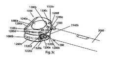
- this recessforms a perimetrical groove (a groove that extends around at least a portion of the perimeter of the static trial, e.g., an annular groove) that establishes a trunk (e.g., a cylindrical trunk) between the baseplates of the static trial, such that the baseplates extend as flanges from either end of the trunk.
- a perimetrical groovea groove that extends around at least a portion of the perimeter of the static trial, e.g., an annular groove
- a trunke.g., a cylindrical trunk
- Additional features that can be used by the static trial holderinclude (on any static trial surface that faces the desired engagement approach direction of the static trial holder, e.g., on each of the anteriorly facing and anterior-laterally facing flat surfaces of the static trial as described below) opposing recesses, preferably formed as upper and lower notches, an upper notch in the upper baseplates and a lower notch in the lower baseplate.
- the notchesare sized so that the opposing notches of each pair form a volume that is dimensioned to closely accommodate the dimensions of the static trial holder's prongs' cross-section.
- each prongis thicker than the semicircular extent that extends from the body, and as such, whereas the semicircular extents fit into the annular groove, the prongs do not because their thickness is greater than the width of the annular groove opening.
- Each notch pairaccommodates this greater thickness, and as such, as the opposing semicircular extents of the static trial holder are placed into the annular groove, the bodies of the prongs of the static trial holder pass into the notches so that the semicircular extents can continue into the annular groove and be seated around the cylindrical trunk.
- interference between the prongs and the notch wallslimits or prevents rotation of the static trial about a longitudinal axis (e.g., an axis parallel to the longitudinal axis of the cylindrical trunk) with respect to the static trial holder.
- each static trial(and each artificial intervertebral disc that the trials approximate) preferably includes an anteriorly facing flat surface, flanked by two anteriolaterally facing flat surfaces (one on each side of the anteriorly facing flat surface), and, to provide for holding of the static trial or disc for an anterior insertion approach, a hole spaced from the anteriorly facing flat surface, the hole having a longitudinal axis parallel to the anteriorly facing flat surface.
- the holding pin of the inserter/impactorfits within the hole, and the angled flat surfaces of the static trial or disc fit against the correspondingly angled flat surfaces of the inserter/impactor, and operation of the inserter/impactor pulls the holding pin toward the flat surface of the inserter/impactor opposite the pin, to rigidly hold the static trial or disc by the baseplate.
- both of the baseplates of the static trial or dischave similarly configured flat surfaces, and both baseplates' flat surfaces fit against the angled flat surfaces of the inserter/impactor to provide for a more secure holding of the static trial or disc by the inserter/impactor.
- each static trial or discalso includes two additional holes, one spaced apart from one of the anteriolaterally facing flat surfaces, and the other spaced apart from the other of the anteriolaterally facing flat surfaces.
- operation of the inserter/impactorcan fit the holding pin into either of these two additional holes, and hold the anteriolaterally facing flat surface (the one associated with the hole into which the pin is fit) of the static trial or disc against the flat surface of the inserter/impactor opposite the pin.
- the angle separating the anteriorly facing flat surface of the static trial or disc and one of the anteriolaterally facing flat surfaces of the static trial or discis equal to the angle separating the anteriorly facing flat surface and the other of the anteriolaterally facing flat surfaces.
- each static trial(and each artificial intervertebral disc that the trials approximate) preferably includes at least two holes extending longitudinally into one of the baseplates of the trial or disc from the inwardly facing surface of the baseplate. More than two holes can be used to provide for multiple repositioning/extracting approaches.
- adjacent holesshould be separated by the same distance separating other adjacent holes.
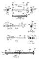
- each repositioner/extractorin order to engage two of the holes, has two pins extending in parallel from a central shaft, perpendicular to the longitudinal axis of the central shaft.
- the pinscan be inserted into the holes, and pulling or pushing on the central shaft along its longitudinal axis when the holes are engaged pulls or pushes the static trial or artificial intervertebral disc in the intervertebral space.
- the static trial or artificial intervertebral disccan be rotated in either direction about a longitudinal axis passing through the intervertebral space, by rotating of the central shaft of the repositioner/extractor about its distal end, about an axis parallel to the longitudinal axes of the pins.
- the pinsare formed on prongs that extend laterally from the central shaft.
- the direction of the prongs, and the location of the pins relative to the central shaft,determine the angle or angles of surgical approach for which a particular repositioner/extractor can be used.
- the number and location of holesfurther determine the angle or angles of surgical approach for which a particular repositioner/extractor can be used. Accordingly, the present invention contemplates a variety of repositioner/extractors, and a variety of holes configurations, to provide the surgeon with a variety of possible surgical approach angles.
- a first hole configurationincludes the hole configuration described above, that is, three holes on one of the baseplates, the holes being configured so that a first hole is located in the anterior-posterior plane, and the adjacent (second and third) holes are located in respective opposing anteriolateral planes on either side of the first hole.
- This first hole configurationis described for and illustrated on both of the baseplates of the static trial of the present invention.
- a second hole configuration(described in the '356 application but not illustrated herein) includes four holes on one of the baseplates (e.g., the upper baseplate), the holes being configured so that first and second holes straddle the anterior-posterior plane, a third hole is located so that the third hole and the first hole straddle one of the opposing anteriolateral planes, and a fourth hole is located so that the fourth hole and the second hole straddle the other of the opposing anteriolateral planes.
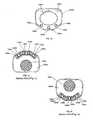
- the static trial holderis provided primarily for use in holding, inserting, removing, and otherwise manipulating the static trials described herein.
- the static trial holderhas at an end of an extension of the static trial holder a pair of opposing prongs that open away from one another and close toward one another.
- Each of the prongshas a semicircular extent and the semicircular extents face one another to define a circular holding enclosure that is useful for capturing the cylindrical trunk of the static trial between them.
- the prongsare spring biased toward a neutral position such that the holding enclosure is spring biased to a receptive state in which the cylindrical trunk can be snapped into (or out of) the holding enclosure by temporarily placing the holding enclosure in an expanded state (by forcing the cylindrical trunk against the mouth of the enclosure) that allows passage of the cylindrical trunk through the mouth of the enclosure.
- the holding enclosurecan be placed in a contracted state, or locked, where the trial is more securely held, so that the trial will not escape the holding enclosure as it is experiencing greater forces while being inserted and removed from the intervertebral space. This locking is effected by rotating a sleeve that surrounds the prongs.
- the bore of the sleeveis configured to press the prongs together when the sleeve is rotated a quarter turn (ninety degrees), and to allow them to separate when the sleeve is reverse rotated a quarter turn (in some embodiments, either quarter turn is in either direction; in the embodiments illustrated herein, the quarter turn that separates the prongs is a reverse rotation of the quarter turn that presses them together).
- the sleevestops its rotation at either the “locked” or “unlocked” states of the holding enclosure, due to radially inwardly directed screw heads on the sleeve's inner surface that ride in ninety-degree arc grooves on the extension's outer surface and that stop when the end of the groove is reached.
- each static trialincludes (on any static trial surface that faces the desired engagement approach direction of the static trial holder, e.g., on each of the anteriorly facing and anterior-laterally facing flat surfaces of the static trial as described below) opposing recesses, preferably formed as upper and lower notches, an upper notch in the upper baseplates and a lower notch in the lower baseplate.
- the notchesare sized so that the opposing notches of each pair form a volume that is dimensioned to closely accommodate the dimensions of the static trial holder's prongs' cross-section.
- each prongis thicker than the semicircular extent that extends from the body, and as such, whereas the semicircular extents fit into the annular groove, the prongs do not because their thickness is greater than the width of the annular groove opening.
- Each notch pairaccommodates this greater thickness, and as such, as the opposing semicircular extents of the static trial holder are placed into the annular groove, the bodies of the prongs of the static trial holder pass into the notches so that the semicircular extents can continue into the annular groove and be seated around the cylindrical trunk.
- interference between the prongs and the notch wallslimits or prevents rotation of the static trial about a longitudinal axis (e.g., an axis parallel to the longitudinal axis of the cylindrical trunk) with respect to the static trial holder.
- the static trial holderis discussed herein as primarily used for manipulating the static trials, it is preferably is also useful for manipulating the distraction spacers described in the '127 application, in that the semicircular extents of the pincers preferably also interact with the annular grooves and cylindrical trunks of those distraction spacers in the same manner as described herein.
- the sleevepreferably has on its exterior surface at least one stop protrusion that is positioned and dimensioned to extend dorsally or ventrally from the exterior surface when the holding enclosure is in its “locked” state, so that when the surgeon inserts the static trial into the intervertebral space, the stop protrusions prevent the static trial from being inserted too far into the space (that is, so that the stop protrusions hit against the lips of the adjacent vertebral body endplates before the static trial is inserted too far).
- FIGS. 1 a-fshow front ( FIG. 1 a ), side ( FIG. 1 b ), perspective ( FIG. 1 c ), top ( FIG. 1 d ), bottom cutaway ( FIG. 1 e ) and top cutaway ( FIG. 1 f ) views of a static trial of the present invention.
- FIGS. 2 a-kshow side ( FIG. 2 a ), top ( FIG. 2 b ), perspective ( FIG. 2 c ), disassembly ( FIG. 2 d 1 , 2 d 2 , 2 d 3 , and 2 e-j ), and side cutaway ( FIG. 2 k ) views of a static trial holder of the present invention.
- FIGS. 3 a-dshow top ( FIG. 3 a ), side ( FIG. 3 b ), and perspective ( FIG. 3 c ) views of the static trial holder of FIGS. 2 a-k holding a static trial of FIGS. 1 a-f from an anterior approach hold
- FIGS. 3 d-eshow top views of the static trial holder of FIGS. 2 a-k holding a static trial of FIGS. 1 a-f from two anterior-lateral approach holds
- FIG. 3 fshows a perspective view of the static trial holder of FIGS. 2 a-k holding a static trial of FIGS. 1 a-f from the anterior-lateral approach hold of FIG. 3 e.
- FIGS. 1 a-fa static trial of the present invention is shown in front ( FIG. 1 a ), side ( FIG. 1 b ), perspective ( FIG. 1 c ), top ( FIG. 1 d ), bottom cutaway ( FIG. 1 e ) and top cutaway ( FIG. 1 f ) views.
- FIGS. 1 g-n of the '356 applicationis merely to show an example of one type of artificial intervertebral disc that is contemplated by, encompassed by, and suitable for use with, the present invention, and that such illustration and reference herein is not meant to limit the scope of the present invention or limit the uses of the present invention. Rather, any other artificial intervertebral disc (or any other orthopedic device) having suitable features for being used with the instrumentation and methods described herein are contemplated by the present invention.
- FIGS. 8 a-ythe features suitable for manipulation (e.g., angled flat surfaces with adjacent holes and/or opposing notches) are encompassed by the present invention, regardless of to what orthopedic device they may be applied.
- Other exemplary suitable artificial intervertebral discsinclude, but are not limited to, the artificial intervertebral discs described in the '160 application with regard to FIGS. 8 a-y , 9 a-t , 10 a-t , 11 a-j , and 12 a-o thereof and by the accompanying descriptions therefor (e.g., embodiments identified as the first, second, third, fourth, and fifth preferred embodiments of the fourth embodiment family, etc.). It should be noted that, as can be seen from FIGS.
- FIGS. 1 g-n of the '356 applicationthat the artificial intervertebral disc shown in FIGS. 1 g-n of the '356 application has features similar to those of these other suitable artificial intervertebral discs of the '160 application, and it should be understood that such similar features are structurally and functionally as described in the '160 application.
- Such similar featuresinclude an inwardly facing surface of the upper baseplate, and a convex structure on the lower baseplate, the convex structure having an inwardly facing surface.
- the toolscan be used with any of the artificial intervertebral discs disclosed in the '356 application or the '160 application, or any other artificial intervertebral disc having (or being modifiable or modified to have) suitable features therefor.
- the features of the artificial intervertebral disce.g., the flat surfaces and accompanying holes
- the static trialse.g., the cylindrical trunks and flat surfaces and accompanying holes and/or engagement notches
- the features of the artificial intervertebral disce.g., the flat surfaces and accompanying holes
- the static trialse.g., the cylindrical trunks and flat surfaces and accompanying holes and/or engagement notches
- the features of the artificial intervertebral disce.g., the flat surfaces and accompanying holes
- the static trialse.g., the cylindrical trunks and flat surfaces and accompanying holes and/or engagement notches
- the inventionencompasses artificial intervertebral discs, spacers, trials (static or dynamic), and/or other orthopedic devices, that have one or more of the features disclosed herein (or in the '356 application), in any combination, and that the invention is therefore not limited to artificial intervertebral discs, spacers, trials, and/or other orthopedic devices having all of the features simultaneously.
- a plurality of static trials 1000are provided primarily for use in determining the appropriate size of an artificial intervertebral disc to be implanted (or whether a particular size of the artificial intervertebral disc can be implanted) into the distracted intervertebral space (e.g., the artificial intervertebral disc 160 of FIGS. 1 g-n of the '356 application).
- the appropriate size of an artificial intervertebral disc to be implantedor whether a particular size of the artificial intervertebral disc can be implanted
- the distracted intervertebral spacee.g., the artificial intervertebral disc 160 of FIGS. 1 g-n of the '356 application.
- a plurality of sizes of the artificial intervertebral discwould be available for each artificial intervertebral disc to be implanted.
- a plurality of the same type of artificial intervertebral discwould be available, each of the plurality having a respective width and depth dimension combination that allows it to fit within a correspondingly dimensioned intervertebral space.
- the plurality of artificial intervertebral discscould include artificial intervertebral discs having widths being either 35 mm or 40 mm, and depths ranging from 14 mm to 18 mm in 1 mm increments, for a total of 10 discs.
- each of the plurality of static trials 1000 for use with a particular plurality of differently sized artificial intervertebral discswould have a respective width and depth dimension set corresponding to the width and depth of a respective one of the plurality of differently sized artificial intervertebral discs.
- the plurality of static trials 1000 for use with the set of artificial intervertebral discs described for examplecould include static trials 1000 having widths being either 35 mm or 40 mm, and depths ranging from 14 mm to 18 mm in 1 mm increments, for a total of 10 static trials.
- the artificial intervertebral discs and/or the static trials 1000can be offered in a variety of dimensions without departing from the scope of the invention, and that the dimensions specifically identified and quantified herein are merely exemplary. Moreover, it should be understood that the set of static trials 1000 need not include the same number of trials for each artificial intervertebral disc in the set of artificial intervertebral discs, but rather, none, one, or more than one trial can be included in the trial set for any particular artificial intervertebral disc in the set.
- Each of the static trialsincludes at least one feature that can be engaged by a tool.
- Suitable toolsinclude, but are not limited to, the static trial holder 2000 described herein, the static trial holder 200 described in the '356 application, the inserter/impactor described in the '356 application, and the repositioners/extractors described in the '356 application.
- the static trial 1000includes a recess 1020 that can be gripped by the opposing semicircular extents 2160 a-b of the static trial holder 2000 .
- this recess 1020forms an annular groove 1040 that establishes a cylindrical trunk 1060 between the upper and lower baseplates 1080 a-b of the static trial 1000 , such that the baseplates 1080 a-b extend as flanges 1100 a-b from either end of the cylindrical trunk 1060 .
- the opposing semicircular extents 2160 a-beach have a thickness smaller than the width of the annular groove 1040 , and as such fit into the annular groove 1040 to grip the cylindrical trunk 1060 between them.
- the body of the prongs 2140 a-b(from which the semicircular extents 2160 a-b extend) has a thickness greater than the width of the annular groove 1040 (and as such does not fit within the annular groove) but small enough to be accommodated by the opposing notches 1320 a-b of the static trial 1000 as described below.)
- annular groove 1040radially widen outwardly, such that the walls 1120 of the annular groove 1040 are tapered toward one another with the increasing depth of the groove 1040 , such that the floor 1140 of the groove 1040 is more narrow than the opening 1160 of the groove 1040 .
- each semicircular extent 2160 a-bcorrespondingly radially widens outwardly, such that the thinner portion of the extent 2160 a-b fits closer to the floor 1140 of the annular groove 1040 , so that the tapered surfaces of the extents 2160 a-b compress against the tapered walls 1120 of the annular groove 1040 when the static trial 1000 is gripped by the static trial holder 2000 .
- This taper lockingprovides for a secure grip so that the static trial 1000 can be manipulated accurately and efficiently.
- the floor of the annular groove 1040 of the cylindrical trunk 1060be ridged (e.g., have ridges that run parallel to the longitudinal axis of the cylindrical trunk), and the surfaces of the semicircular extents 2160 a-b of the static trial holder 2000 that compress against the floor of the annular groove 1040 when the static trial holder 2000 grips the static trial 1000 be correspondingly provided with ridges.
- the interlocking of the ridges of the static trial 1000 with the ridges of the static trial holder 2000 when the static trial 1000 is grippedprevents rotation of the static trial 1000 about the longitudinal axis of the cylindrical trunk 1060 with respect to the static trial holder 2000 .
- each static trial 1000includes (on any static trial surface that faces the desired engagement approach direction of the static trial holder 2000 ) opposing recesses, preferably formed as upper and lower notches, an upper notch in the upper baseplate and a lower notch in the lower baseplate.
- opposing notches 1320 b and 1320 eare on each of the anteriorly facing flat surfaces of the upper 1080 a and lower 1080 b baseplates.
- opposing notches 1320 a and 1320 dare on one of the anterior-laterally facing flat surfaces of the upper 1080 a and lower 1080 b baseplates.
- opposing notches 1320 c and 1320 fare on the other of the anterior-laterally facing flat surfaces of the upper 1080 a and lower 1080 b baseplates.
- the notches 1320 a-fare sized so that the opposing notches of each pair ( 1320 a,d , 1320 b,e , and 1320 c,f ) form a volume that closely accommodates the dimensions of the static trial holder's 2000 prongs' 2140 a-b cross-section.
- each prong 2140 a-bis thicker than the semicircular extent 2160 a-b that extends from the body, and as such, whereas the semicircular extents 2160 a-b fit into the annular groove 1040 , the prongs 2140 a-b do not because the depth 2260 of their cross-section (described below) is greater than the width of the annular groove opening 1160 .
- each notch pair( 1320 a,d , 1320 b,e , and 1320 c,f ) accommodates this greater thickness, in that each notch 1320 a-f has a depth 1340 , and, when the two notch depths 1340 of the opposing notches of the notch pair are taken together with the width of the annular groove 1040 , the combined distance accommodates the depth 2260 of the static trial holder's 2000 prongs' 2140 a-b cross-section. Further, each notch 1320 a-f has a width 1360 that accommodates the width 2240 of the static trial holder's 2000 prongs' 2140 a-b cross-section.
- the width 1360accommodates the width 2240 of the static trial holder's 2000 prongs' 2140 a-b cross-section even when the prongs 2140 a-b are separated to place the holding enclosure 2100 in an expanded state as described below.
- the prongs 2140 a-b of the static trial holder 2000fit into the notches above and below it (e.g., 1320 b and 1320 e for an anterior approach; 1320 a and 1320 d for an anterior-lateral approach; and 1320 c and 1320 f for another anterior-lateral approach).
- the prongs 2140 a-bare fitted within the notch pair, interference between the prongs 2140 a-b and the notch walls limits or prevents rotation of the static trial 1000 about a longitudinal axis (e.g., an axis parallel to the longitudinal axis of the cylindrical trunk 1060 ) with respect to the static trial holder 2000 .
- the inventionencompasses using a single notch in a baseplate, a single notch pair, or any number of notches or notch pairs, formed in any suitable manner with any suitable dimensions, in any number of locations on a spacer, a trial or an artificial intervertebral disc (not limited to locations on the baseplates), for purposes of enabling the spacer, trial, or disc to be engaged by a manipulation instrument (not limited to a static trial holder) that engages the notch, for the purpose of limiting rotation of the spacer, trial, or disc (or other orthopedic implant) with respect to the instrument or for any other purpose, and/or to enable the surgeon to work from a variety of approaches.
- the notch configuration described hereinin cooperation with the static trial holder, provides the surgeon with the ability to work from a directly anterior approach, as well as two anteriolateral approaches.
- additional notch configurationscan enable the surgeon to work from a directly posterior approach, posteriolateral approaches, directly lateral approaches, or anteriolateral approaches that are different than those illustrated.
- the placement of one or more suitably spaced notches (or the addition of one or more notches) on the posterior edge, and/or one or both of the lateral edges of one or both of the baseplateswould enable the surgeon to use the static trial holder of the present invention to achieve such approaches.
- each of the static trials 1000includes at least one feature that can be engaged by a tool that preferably is also used to engage the artificial intervertebral disc that the trial approximates.
- Suitable tools that can grip both the trial and the artificial intervertebral discinclude, but are not limited to, the inserter/impactor described in the '356 application.
- each static trial 1000(and artificial intervertebral disc) includes an anteriorly facing flat surface 1200 b , flanked by two anteriolaterally facing flat surfaces 1200 a and 1200 c (one on each side of the anteriorly facing flat surface 1200 b ), and, to provide for holding of the static trial 1000 (or disc) for an anterior insertion approach, a hole 1220 b spaced from the anteriorly facing flat surface, the hole 1220 b having a longitudinal axis parallel to the anteriorly facing flat surface 1200 b.
- the holding pin of the inserter/impactor described in the '356 applicationfits within the hole 1220 b , and the angled flat surfaces 1200 a-c of the static trial 1000 (or disc) fit against the correspondingly angled flat surfaces (labeled 420 a-c in the '356 application) of the inserter/impactor, and operation of the inserter/impactor pulls the holding pin toward the flat surface of the inserter/impactor opposite the pin, to rigidly hold the static trial 1000 (or disc) by the structure of the static trial 1000 (or disc) having the hole 1220 b (e.g., the baseplate 108 b ).
- both of the baseplates of the static trial 1000have similarly configured flat surfaces.
- the lower baseplate's 1080 b flat surfaces 1200 a-chave similarly configured and similarly oriented counterpart flat surfaces 1200 d-f on the upper baseplate 1080 a .
- both baseplates' 1080 a-b flat surfaces 1200 a-fface the angled flat surfaces of the inserter/impactor when the static trial 1000 (or disc) is held by the inserter/impactor.
- both baseplates' 1080 a-b flat surfaces 1200 a-fface the angled flat surfaces of the inserter/impactor when the static trial 1000 (or disc) is held by the inserter/impactor.
- the flat surfaces 1200 a-c and the counterpart flat surfaces 1200 d-fare tightly held against the angled flat surfaces of the inserter/impactor as described above. It is also preferable that the baseplates 1080 a-b of each of the plurality of static trials 1000 be appropriately lordotically angled relative to one another to ease insertion of the static trial 1000 into the intervertebral space and to mimic how the artificial intervertebral disc will typically be oriented as it is being inserted using the inserter/impactor, and to ease insertion of the static trial 1000 into the intervertebral space. While not shown in FIGS.
- the flat surfaces 1200 d-f on the first (e.g., upper) baseplate 1080 abe parallel to the flat surfaces 1200 a-c of the second (e.g., lower) baseplate 1080 b in the static trial's 1000 appropriately lordotically oriented configuration, so that when the static trial 1000 is held tightly by the inserter/impactor, the flat surfaces 1200 a-f are flush with the flat surfaces of the inserter/impactor even though the baseplates 1080 a-b are lordotically angled with respect to one another.
- each static trial 1000 (or disc)also includes two additional holes 1220 a and 1220 c , one (e.g., 1220 a ) spaced apart from one of the anteriolaterally facing flat surfaces (e.g., 1200 a ), and the other (e.g., 1220 c ) spaced apart from the other of the anteriolaterally facing flat surfaces (e.g., 1200 c ).
- operation of the inserter/impactorcan fit the holding pin into either of these two additional holes 1220 a or 1220 c , and hold the associated anteriolaterally facing flat surface (the one associated with the hole into which the pin is fit) of the static trial 1000 (or disc) against the flat surface of the inserter/impactor opposite the pin.
- the inserter/impactorin a first anteriolateral approach for the trial 1000 (and as can be seen and understood from FIG.
- the angle separating the anteriorly facing flat surface of the static trial 1000 (or disc) and one of the anteriolaterally facing flat surfaces of the static trial 1000 (or disc)is equal to the angle separating the anteriorly facing flat surface and the other of the anteriolaterally facing flat surfaces.
- the surfacesare angled with respect to one another at an angle of 33.4 degrees.
- a trial (or disc)can have angled surfaces (and corresponding holes) along the entire perimeter of one or both of the baseplates, and thus enable the surgeon to engage the trial (or disc) from a number of angles, including anterior, posterior, lateral, anteriolateral, and posteriolateral angles.
- a trial (or disc)can have notches located on directly laterally facing surfaces or posterior surfaces or posterior-laterally facing surfaces, and thus enable the surgeon to engage the trial (or disc) with the static trial holder from a number of angles, including anterior, posterior, lateral, anteriolateral, and posteriolateral angles.
- the opposing notches of the static trialsare shown formed in conjunction with the angulated surfaces of the baseplates, neither the number nor the placement of the opposing notches need coincide or be related to the number or placement of the angulated surfaces of the baseplates.
- the notchescan be applied to a trial or disc having curved approach surfaces.
- each of the static trials 1000includes at least one feature that can be engaged by a tool that preferably is also used to engage the artificial intervertebral disc that the trial approximates.
- Suitable tools that can grip both the trial and the artificial intervertebral discinclude, but are not limited to, the repositioners/extractors described in the '356 application.
- each static trial 1000 (or disc)includes at least two holes extending longitudinally into one of the baseplates of the static trial 1000 (or disc) from the inwardly facing surface of the baseplate. More than two holes can be used to provide for multiple repositioning/extracting approaches.
- adjacent holesshould be separated by the same distance separating other adjacent holes.
- each repositioner/extractorin order to engage two of the holes, each repositioner/extractor has two pins extending in parallel from a central shaft, perpendicular to the longitudinal axis of the central shaft.
- the pinsare spaced to engage the two holes simultaneously, and each pin has a diameter smaller than the diameter of the hole it is to engage. Therefore, the pins can be inserted into the holes, and pulling or pushing on the central shaft along its longitudinal axis when the holes are engaged pulls or pushes the static trial or artificial intervertebral disc in the intervertebral space.
- the static trial or artificial intervertebral disccan be rotated in either direction about a longitudinal axis passing through the intervertebral space, by rotating of the central shaft of the repositioner/extractor about its distal end, about an axis parallel to the longitudinal axes of the pins.
- a handle at a proximal end of the central shaftis useful for pushing or pulling on the shaft.
- a flange adjacent the proximal end of the shaftis useful for impaction (either with a distally directed force or a proximally directed force), if necessary to manipulate the shaft.
- the pinsare formed on prongs that extend laterally from the central shaft.
- the direction of the prongs, and the location of the pins relative to the central shaft,determine the angle or angles of surgical approach for which a particular repositioner/extractor can be used.
- the number and location of holesfurther determine the angle or angles of surgical approach for which a particular repositioner/extractor can be used.
- the present inventioncontemplates a variety of repositioner/extractors, and a variety of holes configurations, to provide the surgeon with a variety of possible surgical approach angles. For example, three repositioner/extractors (symmetric, offset left, and offset right) and two hole configurations are illustrated and described in greater detail in the '356 application.
- the first hole configuration described thereinis illustrated herein on each baseplate 1080 a , 1080 b of the static trials 1000 described herein. That is, referring again to FIGS. 1 a-f , the first hole configuration includes the hole configuration described above, that is, three holes on one of the baseplates (e.g., the lower baseplate 1080 b ), the holes being configured so that a first hole 1220 b is located in the anterior-posterior plane, and the adjacent (second 1220 a and third 1220 c ) holes are located in respective opposing anteriolateral planes on either side of the first hole 1220 b .
- the upper baseplate 1080 aalso includes three similarly configured holes 130 a-c as shown.
- the inventionencompasses using a hole or any number of holes, bored at any suitable angle, whether parallel to other holes or not, in any number of locations on a spacer, a trial or an artificial intervertebral disc (not limited to locations on the baseplates), for purposes of enabling the spacer, trial, or disc to be engaged by a manipulation instrument (not limited to a repositioner/extractor) that engages the hole, and/or to enable the surgeon to work from a variety of approaches.
- the first and second hole configurations described in the '356 application and herein, in cooperation with the repositioner/extractors,provide the surgeon with the ability to work from a directly anterior approach, as well as several anteriolateral approaches.
- additional hole configurationscan enable the surgeon to work from a directly posterior approach, posteriolateral approaches, directly lateral approaches, or anteriolateral approaches that are different than those illustrated.
- the placement of one or more suitably spaced holes (or the addition of one or more holes) on the posterior edge, and/or one or both of the lateral edges of one or both of the baseplateswould enable the surgeon to use the repositioner/extractors of the present invention to achieve such approaches.
- each of the repositioner/extractorscan be used in more than one manner depending on the tool desired and the approach desired. These manners are described in greater detail in the '356 application and illustrated in FIGS. 5p-dd of the '356 application with regard to the detailed description of the repositioners/extractors.
- the baseplates 1080 a-b of each of the plurality of static trials 1000preferably has a convex dome 1240 a-b on its outwardly facing surface 1260 a-b that is shaped like a convex dome on an outwardly facing surface of the corresponding baseplate of the artificial intervertebral disc that the static trial 1000 approximates (e.g., the artificial intervertebral disc 160 described in the '356 application).
- each convex dome 1240 a-bis smooth, rather than having a porous coating that is preferred for the convex domes of the artificial intervertebral disc 160, and each outwardly facing surface 1260 a-b does not have stabilizing spikes such as the stabilizing spikes on the outwardly facing surfaces of the artificial intervertebral disc 160 .
- the omission of these device stabilizing and bone ingrowth encouraging structures and surfaces on the static trials 1000enables the surgeon to test the size of the artificial intervertebral disc to be implanted without traumatically engaging the vertebral body endplates.
- the surgeoncan prepare and distract the intervertebral space, and then insert and remove at least one of the static trials (or more, as necessary) to find the size that is most appropriate for the intervertebral space.
- a static trial holder of the present inventionis shown in side ( FIG. 2 a ), top ( FIG. 2 b ), perspective ( FIG. 2 c ), and side cutaway ( FIG. 2 k ) views.
- a sleeve of the static trial holderis shown in side ( FIG. 2 d 1 ), top ( FIG. 2 d 2 ), side cutaway ( FIG. 2 d 3 ), front ( FIG. 2 e ), and back (with partial cutaway) ( FIG. 2 k ) views.
- FIGS. 2 d 1 , 2 d 2 , 2 d 3 , and 2 e-fa sleeve of the static trial holder is shown in side ( FIG. 2 d 1 ), top ( FIG. 2 d 2 ), side cutaway ( FIG. 2 d 3 ), front ( FIG. 2 e ), and back (with partial cutaway) ( FIG. 2 k ) views.
- FIGS. 2 d 1a static trial holder of the present invention
- FIG. 2 g-ian extension of the static trial holder is shown in top ( FIG. 2 g ), proximal cutaway ( FIG. 2 h ), side ( FIG. 2 i ), and distal cutaway ( FIG. 2 j ) views.
- the static trial holder 2000is provided primarily for use in holding, inserting and removing the static trials 1000 described herein, the static trials 100 described in the '356 application, or other static trials or distraction spacers having suitable features therefor, such as the distraction spacers disclosed in the '127 application.
- the static trial holder 2000includes a handle 2020 , an extension 2040 , and a sleeve 2060 .
- the handle 2020 and the extension 2040are fixed to one another (preferably by the distal end of the handle 2020 being fixed to the proximal end of the extension 2040 ) to form a shaft 2080 .
- the sleeve 2060surrounds the extension 2040 and is rotatable with respect to the handle 2020 and the extension 2040 about the longitudinal axis of the shaft 2080 .
- the handle 2020preferably has an flange 2320 at its proximal end for use in applying a distally or proximally directed force to get the static trial 1000 (or distraction spacer) into or out of the intervertebral space, and/or for use in helping the surgeon rotate the sleeve 2060 with respect to the extension 2040 (by gripping the flange 2320 and the control knob 2190 described below).
- the distal end of the extension 2040forms a contractable and expandable holding enclosure 2100 in that the distal end is divided at a fulcrum 2120 into two prongs 2140 a-b , each of which terminates in a semicircular extent 2160 a-b , each of which has a tapered end 2150 a-b .
- the extents 2160 a-bare oriented such that the tapered ends 2150 a-b face one another to define a radially inwardly tapering mouth 2130 , and such that the semicircular openings oppose one another to define the holding enclosure 2100 .
- the prongs 2140 a-bare spring biased toward a neutral position (preferably by the formation of the fulcrum 2120 in combination with the strength of the material of which the extension 2040 is made) such that the holding enclosure 2100 is spring biased to a receptive state (described below), but the prongs 2140 a-b can be brought together to contract the holding enclosure 2100 to a contracted state, (described below) or the prongs 2140 a-b can be further separated to expand the holding enclosure 2100 to an expanded state (described below).
- the width of the mouth 2130 of the holding enclosure 2100does not accommodate the diameter of the cylindrical trunk 1060 of the static trial 1000 (or distraction spacer) for passage therethrough.
- the mouth 2130can be temporarily widened (placing the holding enclosure 2100 in its expanded state) to accommodate the diameter (for passage of the cylindrical trunk 1060 through the mouth 2130 ), if a sufficient force is applied to overcome the neutral position bias of the prongs 2140 a-b and thus widen the mouth 2130 .
- the prongs 2140 a-bthere is enough space between the outer surfaces of the prongs 2140 a-b and the inner surface of the bore 2180 of the sleeve, when the prongs 2140 a-b are in their neutral position, so that the prongs 2140 a-b can be separated without interference.
- the sufficient forcecan be applied by pressing the cylindrical trunk 1060 against the tapered ends 2150 a-b of the mouth 2130 , in that the separating force component of the radially inward force of the pressing will be applied to the semicircular extents 2160 a-b by the taper of the tapered ends 2150 a-b .
- the holding enclosure 2100Because the holding enclosure 2100 is biased toward the receptive state, after the cylindrical trunk 1060 is passed through the mouth 2130 and into the holding enclosure 2100 , the holding enclosure 2100 will return to its receptive state in which the width of the mouth 2130 does not allow passage of the cylindrical trunk 1060 without the sufficient force.
- the force required to widen the mouth 2130is greater than gravity and/or the greatest force that will be experienced by moving the static trial holder 2000 prior to placing the holding enclosure 2100 in the contracted state. Therefore, once the cylindrical trunk 1060 is in the holding enclosure 2100 , even before the holding enclosure 2100 is placed in its contracted state, the cylindrical trunk 1060 will not escape the holding enclosure 2100 as the static trial holder 2000 is oriented with the holding enclosure 2100 downward, or is moved about.
- the static trial 1000(or distraction spacer) is being held (either when the holding enclosure 2100 is in its receptive state or in its contracted state discussed below), because the semicylindrical extents 2160 a-b fit within the annular groove 1040 of the static trial 1000 (or distraction spacer), the static trial 1000 (or distraction spacer) will not escape from the enclosure along the longitudinal axis of the cylindrical trunk 1060 . That is, as noted above, the recess 1020 of each static trial 1000 (or distraction spacer) forms an annular groove 1040 that establishes the cylindrical trunk 1060 between the baseplates of the static trial (or distraction spacer), such that the baseplates extend as flanges from either end of the cylindrical trunk 1060 . Accordingly, preferably, the opposing semicircular extents each have a thickness smaller than the width of the annular groove 1040 , and as such fit into the annular groove 1040 to grip the cylindrical trunk 1060 between them.
- annular groove 1040radially widen outwardly, such that the walls of the annular groove 1040 taper toward one another with the increasing depth of the groove, such that the floor of the groove is more narrow than the opening 1160 of the groove.
- each semicircular extent 2160 a-bcorrespondingly radially widens outwardly, such that the thinner portion of the extent 2160 a-b fits closer to the floor of the annular groove 1040 , so that the tapered surfaces 2150 a-b of the extents 2160 a-b compress against the tapered walls of the annular groove 1040 when the static trial 1000 is gripped by the static trial holder 2000 .
- This taper lockingprovides for a secure grip so that the static trial 1000 can be manipulated accurately and efficiently.
- the floor of the annular groove 1040 of the cylindrical trunk 1060be ridged (e.g., have ridges that run parallel to the longitudinal axis of the cylindrical trunk), and the surfaces of the semicircular extents 2160 a-b of the static trial holder 2000 that compress against the floor of the annular groove 1040 when the static trial holder 2000 grips the static trial 1000 be correspondingly provided with ridges.
- the interlocking of the ridges of the static trial 1000 with the ridges of the static trial holder 2000 when the static trial 1000 is grippedprevents rotation of the static trial 1000 about the longitudinal axis of the cylindrical trunk 1060 with respect to the static trial holder 2000 .
- the holding enclosure 2100can be placed in a contracted state.
- the holding enclosure 2100can be considered “unlocked” in its receptive or expanded states, and “locked” in its contracted state, with respect to the nature of the hold that the static trial holder 2000 potentially can have or has on the cylindrical trunk 1060 .
- a force greater than that which is applicable by an unaided surgeon or nursei.e., that which can be applied to remove the cylindrical trunk 1060 from the holding enclosure 2100 when the holding enclosure 2100 is in its receptive state
- a force greater than that which will be experienced by the static trial 1000 (or distraction spacer) and the static trial holder 2000 during surgical procedureswould be required to pull the cylindrical trunk 1060 out of the holding enclosure 2100 .
- the placement of the holding enclosure 2100 in its locked state or unlocked stateis effected by operation of a holding assembly that includes the extension 2040 and the sleeve 2060 and the manner in which they are configured and interact.
- the prongs 2140 a-bcan be brought together (or brought closer to one another; it should be understood that they need not touch to be encompassed by the present invention), to lock the holding enclosure 2100 , by a rotation of the sleeve 2060 with respect to the handle 2020 and the extension 2040 about the longitudinal axis of the shaft 2080 .
- a rotation control knob 2190is provided to ease the rotation of the sleeve 2060 .
- FIGS. 2 g and 2 i-jin view of FIGS. 2 d 1 , 2 d 2 , 2 d 3 , and 2 e , the bore 2180 of the sleeve 2060 (shown in front view in FIG.
- the prongs 2140 a-b when separateddefine a cross-section having a width 2240 that is greater than its depth 2260 , the width 2240 and depth 2260 of the prongs' cross-section being closely accommodated by the width 2200 and depth 2220 of the bore's cross-section.
- the width of prongs' cross-sectionis closely accommodated by the depth 2220 of the bore's cross-section.
- the corners of the bore 2180are radiused, and at least the sides (that face away from one another) of the prongs 2140 a-b are curved.
- the prongs 2140 a-b when separateddefine a partial cylindrical cross-section.
- the effect of the bearing (of the sides of the bore 2180 against the sides of the prongs 2140 a-b )is borne by the space between the prongs 2140 a-b , so that the space narrows and the prongs 2140 a-b are brought toward one another until they are accommodated within the bore's depth 2220 .
- the bringing together of the prongs 2140 a-bbrings the semicircular extents 2160 a-b together to place the holding enclosure 2100 into its contracted state, locking it.
- the movement of the sleeve 2060 toward positions that will either unlock or lock the holding enclosure 2100 , and the stopping of the sleeve 2060 at such positions,is effected by the inclusion of at least one groove 2280 that extends in a 90 degree arc on the outer surface of the extension 2040 , and at least one radial bore 2300 through the wall of the sleeve 2060 (preferably through the rotation control knob 2190 as shown), which bores 2300 each have secured therein a dog headed screw (not shown) so that a head of the screw protrudes into interior of the sleeve (it should be understood that functionally equivalent devices can also be used in place of a dog headed screw).
- each groove 2280is associated with a respective cooperating bore 2300 and dog headed screw.
- a given bore 2300 (and dog headed screw)is aligned with an end of its associated groove 2280 , the sleeve 2060 is in a position at which the holding enclosure 2100 is either unlocked or locked (unlocked when the head of the screw is positioned at one end of the groove, locked when it is positioned at the other end of the groove).
- the head of the dog headed screwprotrudes into the interior of the sleeve and into the groove 2280 and rides therein as the sleeve 2060 is rotated.
- the head of the screwstops against the wall of the groove 2280 at the end of the groove 2280 , stopping the rotation of the sleeve 2060 , and setting the holding enclosure 2100 to either the unlocked or locked position.
- the sleeve 2060is reverse rotated, causing the head of the screw to ride in the groove 2280 in the opposite direction toward the other end of the groove 2280 .
- the head of the screwWhen the head of the screw reaches the other end of the groove 2280 , the head of the screw stops against the wall of the groove 2280 at that end of the groove 2280 , stopping the rotation of the sleeve 2060 , and setting the holding enclosure 2100 to the alternative position.
- the sleeve 2060preferably has on its exterior surface at least one stop protrusion 1380 that is positioned and dimensioned to extend dorsally or ventrally from the exterior surface when the holding enclosure is in its “locked” state (see FIGS. 3 a-f ), so that when the surgeon inserts the static trial 1000 into the intervertebral space, the stop protrusions 1380 prevent the static trial 1000 from being inserted too far into the space (that is, so that the stop protrusions 1380 hit against the lips of the adjacent vertebral body endplates before the static trial 1000 is inserted too far).
- the static trials 1000 of the inventioncan be held and manipulated with the static trial holder 2000 from a variety of approach angles. Holding the handle 2020 of the static trial holder 2000 in one hand, an operator can push the cylindrical trunk 1060 of the static trial 1000 (or the distraction spacer) against the mouth 2130 of the holding enclosure 2100 with enough force to temporarily expand the mouth 2130 to a width that will accommodate the diameter of the cylindrical trunk 1060 for passage through the mouth 2130 .
- the depth 2260 of the prongs' cross-sectionis closely accommodated by the depth of the opening establishing by the width of the annular groove 1020 and the depths 1340 of the notches in the pair of opposing notches ( 1320 a,d , 1320 b,d , or 1320 c,f ), and the width 2240 of the prongs' cross-section is accommodated by the width 1360 of the notches in the pair of opposing notches ( 1320 a,d , 1320 b,d , or 1320 c,f ), so that the prongs' cross-section fits into the opposing notches as, and when, the cylindrical trunk 1060 is surrounded by the semicircular extents 2160 a-b .
- the width 1360 of the notch pairaccommodates the width 2240 of the static trial holder's 2000 prongs' 2140 a-b cross-section even when the prongs 2140 a-b are separated to place the holding enclosure 2100 in an expanded state as described below.
- Thisenables the notch pair to accommodate the width 2240 of the prongs' cross-section as the cylindrical trunk 1060 of the static trial 1000 is being snapped into the holding enclosure 2100 .
- the operatorcan let go of the static trial 1000 (or distraction spacer) because the prongs 2140 a-b will be overcome by their bias toward their neutral state and thus hold the static trial 1000 in the holding enclosure 2100 to prevent the static trial 1000 from falling out or slipping out as the static trial holder 2000 is moved with the static trial 1000 prior to closing (e.g., locking) the holding enclosure 2100 .
- the static trial 1000(or distraction spacer) is being held in this manner, and the holding enclosure 2100 is unlocked, the static trial 1000 can be removed from the holding enclosure 2100 by a pulling of the static trial 1000 through the mouth 2130 of the holding enclosure 2100 with a force required to again temporarily overcome the bias of the prongs 2140 a-b toward their neutral state, to separate them and make the width of the mouth 2130 accommodate the diameter of the cylindrical trunk 1060 .)
- the rotation control knob 2190clockwise (or counterclockwise depending on how the grooves 2280 are configured; that is, they are illustrated as being configured to enable a locking with a clockwise rotation, and an unlocking with a subsequent counterclockwise rotation, although other embodiments can enable a locking with a counterclockwise rotation, and an unlocking with a clockwise rotation, to accommodate left-handed persons or right-handed persons or for other reasons) to rotate the sleeve 2060 ninety degrees to the next position.
- the head of the dog headed screwrides freely in the groove 2280 , and the sides of the sleeve's bore's inner surface bear against the curved outer surfaces of the prongs 2140 a-b to push the prongs 2140 a-b together so that they are accommodated by the depth 2220 of the bore 2180 .
- the prongs 2140 a-bare pressed against one another and the semicircular extents 2160 a-b move toward one another.
- the prongs 2140 a-bare held in and biased toward the closed position, and the semicircular extents 2160 a-b are correspondingly maintained together about the cylindrical trunk 1060 , by the fitting of the bore's surfaces against the prongs' surfaces.
- the cylindrical trunk 1060cannot be removed through the mouth 2130 of the now-tighter (e.g., locked) holding enclosure 2100 without the application of forces preferably greater than will be encountered when inserting and removing the static trial 1000 from the intervertebral space during the surgical procedures.
- the interference between the prongs 2140 a-b and the opposing notches in the notch pair in which the prongs 2140 a-b are disposedprevents rotation of the static trial 1000 about a longitudinal axis (e.g., an axis parallel to the longitudinal axis of the cylindrical trunk 1060 ) with respect to the static trial holder 2000 . That is, if the static trial 1000 is encouraged, by forces encountered during manipulation of the static trial 1000 , to rotate about such an axis with respect to the static trial holder 2000 , the side walls of the notches will be confronted by the prong 2140 a-b bodies and such rotational movement of the static trial 1000 will be stopped. (As can be seen in the FIGS. 3 a-f , the prongs 2140 a-b are too deep to fit into the annular groove 1060 without the notch pair accommodating their depth.) The same will happen if a reverse rotation about such an axis is attempted.
- a longitudinal axise.g., an
- the operatorcan unlock the holding enclosure 2100 by reverse rotating the sleeve 2060 (with enough initial force to overcome the biasing of the fitting of the bore's and the prongs' surfaces) ninety degrees. Again, as the sleeve 2060 rotates, the sides of the sleeve's bore's inner surface move away from the curved outer surfaces of the prongs 2140 a-b and allow the prongs 2140 a-b to separate (under their own bias toward the neutral position) as they are accommodated by the width 2200 of the bore 2180 .
- the prongs 2140 a-bare separated and allowed to remain in that position by the maintenance of the sleeve 2060 in the new position (with the head of the dog headed screw against the wall of the groove 2280 at the other end of the groove 2280 ), the semicircular extents 2160 a-b are separated from one another and hold the cylindrical trunk 1060 against falling or slipping out. That is, the cylindrical trunk 1060 can be removed by the operator if the operator applies a sufficient force to widen the mouth 2130 of the holding enclosure 2100 enough to let the cylindrical trunk 1060 pass through the mouth 2130 . Once the static trial 1000 (or distraction spacer) is removed, another one can be inserted and manipulated if required. As shown in FIGS. 3 d-f , in addition to the anterior approach angle shown in FIGS. 3 a-c , the illustrated notch configuration accommodates two anterior-lateral approach angles as well.
- the static trial holder 2000can be used to insert and remove the distraction spacers of the '127 application to distract the intervertebral space as described in the '127, and thereafter (or during the distraction) hold to insert and remove the static trials 1000 to find the appropriate size of artificial intervertebral disc to be implanted.
Landscapes
- Health & Medical Sciences (AREA)
- Engineering & Computer Science (AREA)
- Biomedical Technology (AREA)
- Orthopedic Medicine & Surgery (AREA)
- Transplantation (AREA)
- Neurology (AREA)
- Heart & Thoracic Surgery (AREA)
- Oral & Maxillofacial Surgery (AREA)
- Cardiology (AREA)
- Vascular Medicine (AREA)
- Life Sciences & Earth Sciences (AREA)
- Animal Behavior & Ethology (AREA)
- General Health & Medical Sciences (AREA)
- Public Health (AREA)
- Veterinary Medicine (AREA)
- Physical Education & Sports Medicine (AREA)
- Prostheses (AREA)
Abstract
Description
Claims (12)
Priority Applications (23)
| Application Number | Priority Date | Filing Date | Title |
|---|---|---|---|
| US10/309,585US7115132B2 (en) | 2001-07-16 | 2002-12-04 | Static trials and related instruments and methods for use in implanting an artificial intervertebral disc |
| US10/663,492US7223291B2 (en) | 2001-07-16 | 2003-09-16 | Intervertebral spacer device having engagement hole pairs for manipulation using a surgical tool |
| US10/663,493US8366775B2 (en) | 2001-07-16 | 2003-09-16 | Intervertebral spacer device having an angled perimeter for manipulation using a surgical tool |
| JP2005501875AJP4654125B2 (en) | 2002-10-29 | 2003-09-16 | Instruments, methods, and functions for use in implanting an artificial disc |
| CA2632125ACA2632125C (en) | 2002-10-29 | 2003-09-16 | Instrumentation, methods and features for use in implanting an artificial intervertebral disc |
| EP03749686AEP1555966A4 (en) | 2002-10-29 | 2003-09-16 | Instrumentation, methods, and features for use in implanting an artificial intervertebral disc |
| US10/663,486US7491241B2 (en) | 2001-07-16 | 2003-09-16 | Intervertebral spacer device having recessed notch pairs for manipulation using a surgical tool |
| US10/663,487US7635368B2 (en) | 2001-07-16 | 2003-09-16 | Intervertebral spacer device having simultaneously engageable angled perimeters for manipulation using a surgical tool |
| CA002503848ACA2503848C (en) | 2002-10-29 | 2003-09-16 | Instrumentation, methods, and features for use in implanting an artificial intervertebral disc |
| US10/663,488US7811287B2 (en) | 2001-07-16 | 2003-09-16 | Intervertebral spacer device having an engagement hole for a tool with an extendable post |
| AU2003267215AAU2003267215B2 (en) | 2002-10-29 | 2003-09-16 | Instrumentation, methods, and features for use in implanting an artificial intervertebral disc |
| PCT/US2003/028957WO2004039291A1 (en) | 2002-10-29 | 2003-09-16 | Instrumentation, methods, and features for use in implanting an artificial intervertebral disc |
| CA2632115ACA2632115C (en) | 2002-10-29 | 2003-09-16 | Instrumentation, methods and features for use in implanting an artificial intervertebral disc |
| US11/716,360US8303659B2 (en) | 2001-07-16 | 2007-03-09 | Intervertebral spacer device having engagement hole pairs |
| US12/321,562US8940047B2 (en) | 2001-02-15 | 2009-01-22 | Intervertebral spacer device having recessed notch pairs for manipulation using a surgical tool |
| AU2009200850AAU2009200850B2 (en) | 2002-10-29 | 2009-03-03 | Instrumentation, methods, and features for use in implanting an artificial intervertebral disc |
| JP2009151399AJP4979741B2 (en) | 2002-10-29 | 2009-06-25 | Intervertebral spacer instrument and tool set for use in implanting an artificial disc |
| US12/938,080US8545564B2 (en) | 2001-07-16 | 2010-11-02 | Intervertebral spacer device having an articulation member and housing |
| AU2011200915AAU2011200915B2 (en) | 2002-10-29 | 2011-03-02 | Instrumentation, methods, and features for use in implanting an artificial intervertebral disc |
| US14/340,091US9814596B2 (en) | 2001-07-16 | 2014-07-24 | Method of orienting an intervertebral spacer device having recessed notch pairs by using a surgical tool |
| US15/014,803US9700429B2 (en) | 2001-07-16 | 2016-02-03 | Intervertebral spacer device having recessed notch pairs for manipulation using a surgical tool |
| US15/618,566US20170273805A1 (en) | 2001-07-16 | 2017-06-09 | Intervertebral spacer device having recessed notch pairs for manipulation using a surgical tool |
| US15/726,958US20180028330A1 (en) | 2001-07-16 | 2017-10-06 | Intervertebral spacer device having recessed notch pairs for manipulation using a surgical tool |
Applications Claiming Priority (11)
| Application Number | Priority Date | Filing Date | Title |
|---|---|---|---|
| US09/906,119US6607559B2 (en) | 2001-07-16 | 2001-07-16 | Trial intervertebral distraction spacers |
| US09/968,046US20020111687A1 (en) | 2001-02-15 | 2001-10-01 | Intervertebral spacer device utilizing a belleville washer having radially extending grooves |
| US09/970,479US6669730B2 (en) | 2001-02-15 | 2001-10-04 | Intervertebral spacer device utilizing a spirally slotted belleville washer having radially extending grooves |
| US09/982,148US6673113B2 (en) | 2001-10-18 | 2001-10-18 | Intervertebral spacer device having arch shaped spring elements |
| US10/128,619US6863689B2 (en) | 2001-07-16 | 2002-04-23 | Intervertebral spacer having a flexible wire mesh vertebral body contact element |
| US10/140,153US20030069642A1 (en) | 2001-10-04 | 2002-05-07 | Artificial intervertebral disc having a flexible wire mesh vertebral body contact element |
| US10/151,280US7604664B2 (en) | 2001-07-16 | 2002-05-20 | Spinal baseplates with ball joint coupling and a retaining member |
| US10/175,417US7563285B2 (en) | 2001-07-16 | 2002-06-19 | Artificial intervertebral disc utilizing a ball joint coupling |
| US10/256,160US6989032B2 (en) | 2001-07-16 | 2002-09-26 | Artificial intervertebral disc |
| US10/282,356US7169182B2 (en) | 2001-07-16 | 2002-10-29 | Implanting an artificial intervertebral disc |
| US10/309,585US7115132B2 (en) | 2001-07-16 | 2002-12-04 | Static trials and related instruments and methods for use in implanting an artificial intervertebral disc |
Related Parent Applications (11)
| Application Number | Title | Priority Date | Filing Date |
|---|---|---|---|
| US09/968,046ContinuationUS20020111687A1 (en) | 2001-02-15 | 2001-10-01 | Intervertebral spacer device utilizing a belleville washer having radially extending grooves |
| US09/968,046Continuation-In-PartUS20020111687A1 (en) | 2001-02-15 | 2001-10-01 | Intervertebral spacer device utilizing a belleville washer having radially extending grooves |
| US09/970,479ContinuationUS6669730B2 (en) | 2001-02-15 | 2001-10-04 | Intervertebral spacer device utilizing a spirally slotted belleville washer having radially extending grooves |
| US09/982,148Continuation-In-PartUS6673113B2 (en) | 2001-02-15 | 2001-10-18 | Intervertebral spacer device having arch shaped spring elements |
| US10/128,619Continuation-In-PartUS6863689B2 (en) | 2001-02-15 | 2002-04-23 | Intervertebral spacer having a flexible wire mesh vertebral body contact element |
| US10/140,153Continuation-In-PartUS20030069642A1 (en) | 2001-02-15 | 2002-05-07 | Artificial intervertebral disc having a flexible wire mesh vertebral body contact element |
| US10/256,160Continuation-In-PartUS6989032B2 (en) | 2001-02-15 | 2002-09-26 | Artificial intervertebral disc |
| US10/282,356Continuation-In-PartUS7169182B2 (en) | 2001-02-15 | 2002-10-29 | Implanting an artificial intervertebral disc |
| US10/425,267Continuation-In-PartUS7235081B2 (en) | 2001-02-15 | 2003-04-29 | Wedge plate inserter/impactor and related methods for use in implanting an artificial intervertebral disc |
| US10/663,487Continuation-In-PartUS7635368B2 (en) | 2001-07-16 | 2003-09-16 | Intervertebral spacer device having simultaneously engageable angled perimeters for manipulation using a surgical tool |
| US10/663,493Continuation-In-PartUS8366775B2 (en) | 2001-07-16 | 2003-09-16 | Intervertebral spacer device having an angled perimeter for manipulation using a surgical tool |
Related Child Applications (7)
| Application Number | Title | Priority Date | Filing Date |
|---|---|---|---|
| US10/282,356Continuation-In-PartUS7169182B2 (en) | 2001-02-15 | 2002-10-29 | Implanting an artificial intervertebral disc |
| US10/425,267Continuation-In-PartUS7235081B2 (en) | 2001-02-15 | 2003-04-29 | Wedge plate inserter/impactor and related methods for use in implanting an artificial intervertebral disc |
| US10/663,492Continuation-In-PartUS7223291B2 (en) | 2001-02-15 | 2003-09-16 | Intervertebral spacer device having engagement hole pairs for manipulation using a surgical tool |
| US10/663,492ContinuationUS7223291B2 (en) | 2001-02-15 | 2003-09-16 | Intervertebral spacer device having engagement hole pairs for manipulation using a surgical tool |
| US10/663,487Continuation-In-PartUS7635368B2 (en) | 2001-07-16 | 2003-09-16 | Intervertebral spacer device having simultaneously engageable angled perimeters for manipulation using a surgical tool |
| US10/663,493ContinuationUS8366775B2 (en) | 2001-07-16 | 2003-09-16 | Intervertebral spacer device having an angled perimeter for manipulation using a surgical tool |
| US10/663,488Continuation-In-PartUS7811287B2 (en) | 2001-07-16 | 2003-09-16 | Intervertebral spacer device having an engagement hole for a tool with an extendable post |
Publications (2)
| Publication Number | Publication Date |
|---|---|
| US20030078590A1 US20030078590A1 (en) | 2003-04-24 |
| US7115132B2true US7115132B2 (en) | 2006-10-03 |
Family
ID=32777440
Family Applications (1)
| Application Number | Title | Priority Date | Filing Date |
|---|---|---|---|
| US10/309,585Expired - Fee RelatedUS7115132B2 (en) | 2001-02-15 | 2002-12-04 | Static trials and related instruments and methods for use in implanting an artificial intervertebral disc |
Country Status (1)
| Country | Link |
|---|---|
| US (1) | US7115132B2 (en) |
Cited By (68)
| Publication number | Priority date | Publication date | Assignee | Title |
|---|---|---|---|---|
| US20030069643A1 (en)* | 2001-07-16 | 2003-04-10 | Ralph James D. | Tension bearing artificial disc providing a centroid of motion centrally located within an intervertebral space |
| US20040167536A1 (en)* | 2001-07-16 | 2004-08-26 | Errico Joseph P. | Instrumentation for properly seating an artificial intervertebral disc in an intervertebral space |
| US20050060035A1 (en)* | 2001-07-16 | 2005-03-17 | Errico Joseph P. | Intervertebral spacer device having recessed notch pairs for manipulation using a surgical tool |
| US20060235426A1 (en)* | 2005-04-15 | 2006-10-19 | Sdgi Holdings, Inc. | Instruments, implants and methods for positioning implants into a spinal disc space |
| US20070173941A1 (en)* | 2006-01-25 | 2007-07-26 | Sdgi Holdings, Inc. | Intervertebral prosthetic disc and method of installing same |
| US20070233152A1 (en)* | 2006-03-17 | 2007-10-04 | Shawn Stad | Arthroplasty final seating instruments |
| US20080027544A1 (en)* | 2006-07-28 | 2008-01-31 | Warsaw Orthopedic Inc. | Instruments and techniques for engaging spinal implants for insertion into a spinal space |
| US20080154381A1 (en)* | 2006-12-21 | 2008-06-26 | Rob Gene Parrish | Intervertebral disc spacer |
| US20090024164A1 (en)* | 2007-06-25 | 2009-01-22 | Neubardt Seth L | System for determining spinal implants |
| US20090054901A1 (en)* | 2007-08-20 | 2009-02-26 | Oh Younghoon | Inserter device used for orthopedic surgery |
| US20090222101A1 (en)* | 2003-05-27 | 2009-09-03 | Spinalmotion, Inc. | Prosthetic Disc for Intervertebral Insertion |
| WO2010009151A3 (en)* | 2008-07-17 | 2010-05-06 | Spinalmotion, Inc. | Artificial intervertebral disc placement system |
| US7713302B2 (en) | 2001-10-01 | 2010-05-11 | Spinecore, Inc. | Intervertebral spacer device utilizing a spirally slotted belleville washer having radially spaced concentric grooves |
| US20100158209A1 (en)* | 2008-12-22 | 2010-06-24 | General Instrument Corporation | Access to Network Based on Automatic Speech-Recognition |
| US7771477B2 (en) | 2001-10-01 | 2010-08-10 | Spinecore, Inc. | Intervertebral spacer device utilizing a belleville washer having radially spaced concentric grooves |
| US20100262245A1 (en)* | 2009-02-18 | 2010-10-14 | Alfaro Arthur A | Intervertebral spacer |
| US7815648B2 (en) | 2004-06-02 | 2010-10-19 | Facet Solutions, Inc | Surgical measurement systems and methods |
| EP2241291A2 (en) | 2006-09-21 | 2010-10-20 | SpineCore, Inc. | Intervertebral disc implants and tooling |
| US20110022089A1 (en)* | 2009-07-24 | 2011-01-27 | Zyga Technology, Inc | Systems and methods for facet joint treatment |
| US7914560B2 (en) | 2004-02-17 | 2011-03-29 | Gmedelaware 2 Llc | Spinal facet implant with spherical implant apposition surface and bone bed and methods of use |
| US20110092859A1 (en)* | 2007-06-25 | 2011-04-21 | Neubardt Seth L | System for determining and placing spinal implants or prostheses |
| US20110166654A1 (en)* | 2005-04-08 | 2011-07-07 | G&L Consulting | Spine implant insertion device and method |
| US7976549B2 (en) | 2006-03-23 | 2011-07-12 | Theken Spine, Llc | Instruments for delivering spinal implants |
| US7988695B2 (en) | 2005-12-21 | 2011-08-02 | Theken Spine, Llc | Articulated delivery instrument |
| US8002834B2 (en) | 2004-07-30 | 2011-08-23 | Spinalmotion, Inc. | Intervertebral prosthetic disc with metallic core |
| US8029568B2 (en) | 2001-10-18 | 2011-10-04 | Spinecore, Inc. | Intervertebral spacer device having a slotted partial circular domed arch strip spring |
| US8083797B2 (en) | 2005-02-04 | 2011-12-27 | Spinalmotion, Inc. | Intervertebral prosthetic disc with shock absorption |
| US8090428B2 (en) | 2003-01-31 | 2012-01-03 | Spinalmotion, Inc. | Spinal midline indicator |
| US8100972B1 (en) | 2007-07-02 | 2012-01-24 | Theken Spine, Llc | Spinal cage having deployable member |
| US8109979B2 (en) | 2003-03-06 | 2012-02-07 | Spinecore, Inc. | Instrumentation and methods for use in implanting a cervical disc replacement device |
| US8206418B2 (en) | 2007-01-10 | 2012-06-26 | Gmedelaware 2 Llc | System and method for facet joint replacement with detachable coupler |
| US8206447B2 (en) | 2004-08-06 | 2012-06-26 | Spinalmotion, Inc. | Methods and apparatus for intervertebral disc prosthesis insertion |
| US8267997B2 (en) | 2007-11-12 | 2012-09-18 | Theken Spine, Llc | Vertebral interbody compression implant |
| US8277507B2 (en) | 2002-04-12 | 2012-10-02 | Spinecore, Inc. | Spacerless artificial disc replacements |
| US8292958B1 (en) | 2007-07-02 | 2012-10-23 | Theken Spine, Llc | Spinal cage having deployable member |
| US8343189B2 (en) | 2007-09-25 | 2013-01-01 | Zyga Technology, Inc. | Method and apparatus for facet joint stabilization |
| US8470041B2 (en) | 2002-04-12 | 2013-06-25 | Spinecore, Inc. | Two-component artificial disc replacements |
| US8506636B2 (en) | 2006-09-08 | 2013-08-13 | Theken Spine, Llc | Offset radius lordosis |
| US8506631B2 (en) | 2007-08-09 | 2013-08-13 | Spinalmotion, Inc. | Customized intervertebral prosthetic disc with shock absorption |
| US8545562B1 (en) | 2007-07-02 | 2013-10-01 | Theken Spine, Llc | Deployable member for use with an intervertebral cage |
| US8663293B2 (en) | 2010-06-15 | 2014-03-04 | Zyga Technology, Inc. | Systems and methods for facet joint treatment |
| US8696707B2 (en) | 2005-03-08 | 2014-04-15 | Zyga Technology, Inc. | Facet joint stabilization |
| US8734519B2 (en) | 2006-04-12 | 2014-05-27 | Spinalmotion, Inc. | Posterior spinal device and method |
| US8758441B2 (en) | 2007-10-22 | 2014-06-24 | Spinalmotion, Inc. | Vertebral body replacement and method for spanning a space formed upon removal of a vertebral body |
| US8777994B2 (en) | 2004-06-02 | 2014-07-15 | Gmedelaware 2 Llc | System and method for multiple level facet joint arthroplasty and fusion |
| US8777959B2 (en) | 2005-05-27 | 2014-07-15 | Spinecore, Inc. | Intervertebral disc and insertion methods therefor |
| US8845730B2 (en) | 2008-07-18 | 2014-09-30 | Simplify Medical, Inc. | Posterior prosthetic intervertebral disc |
| US8858564B2 (en)* | 2001-02-15 | 2014-10-14 | Spinecore, Inc. | Wedge plate inserter/impactor and related methods for use in implanting an artificial intervertebral disc |
| US8864829B1 (en) | 2007-07-02 | 2014-10-21 | Theken Spine, Llc | Spinal cage having deployable member |
| US20150025639A1 (en)* | 2009-11-05 | 2015-01-22 | DePuy Synthes Products, LLC | Self-pivoting spinal implant and associated instrumentation |
| US9011544B2 (en) | 2008-05-05 | 2015-04-21 | Simplify Medical, Inc. | Polyaryletherketone artificial intervertebral disc |
| US9034038B2 (en) | 2008-04-11 | 2015-05-19 | Spinalmotion, Inc. | Motion limiting insert for an artificial intervertebral disc |
| US9084688B2 (en) | 2009-05-19 | 2015-07-21 | DePuy Synthes Products, Inc. | Dynamic trial implants |
| US20150245919A1 (en)* | 2012-10-24 | 2015-09-03 | Waldemar Link Gmbh & Co. Kg | Holder for a medical implant |
| US9220603B2 (en) | 2008-07-02 | 2015-12-29 | Simplify Medical, Inc. | Limited motion prosthetic intervertebral disc |
| US9233006B2 (en) | 2010-06-15 | 2016-01-12 | Zyga Technology, Inc. | Systems and methods for facet joint treatment |
| US9402745B2 (en) | 2003-01-31 | 2016-08-02 | Simplify Medical, Inc. | Intervertebral prosthesis placement instrument |
| US9445918B1 (en) | 2012-10-22 | 2016-09-20 | Nuvasive, Inc. | Expandable spinal fusion implants and related instruments and methods |
| US9451940B2 (en) | 2008-12-26 | 2016-09-27 | Pantheon Spinal, Llc | Method of retroperitoneal lateral insertion of spinal implants |
| US9655741B2 (en) | 2003-05-27 | 2017-05-23 | Simplify Medical Pty Ltd | Prosthetic disc for intervertebral insertion |
| US9833328B2 (en) | 2010-06-15 | 2017-12-05 | Zyga Technology | System and methods for facet joint treatment |
| US10022245B2 (en) | 2012-12-17 | 2018-07-17 | DePuy Synthes Products, Inc. | Polyaxial articulating instrument |
| US10342674B2 (en) | 2007-07-02 | 2019-07-09 | Theken Spine, Llc | Spinal cage having deployable member |
| US10716553B2 (en) | 2017-04-19 | 2020-07-21 | Pantheon Spinal, Llc | Spine surgery retractor system and related methods |
| US10966843B2 (en) | 2017-07-18 | 2021-04-06 | DePuy Synthes Products, Inc. | Implant inserters and related methods |
| US11045331B2 (en) | 2017-08-14 | 2021-06-29 | DePuy Synthes Products, Inc. | Intervertebral implant inserters and related methods |
| US11096802B2 (en) | 2018-03-03 | 2021-08-24 | K2M, Inc. | Intervertebral trial with marker |
| US12186201B2 (en) | 2007-07-02 | 2025-01-07 | Theken Spine, Llc | Spinal cage having deployable member |
Families Citing this family (40)
| Publication number | Priority date | Publication date | Assignee | Title |
|---|---|---|---|---|
| US6478800B1 (en) | 2000-05-08 | 2002-11-12 | Depuy Acromed, Inc. | Medical installation tool |
| US6706068B2 (en) | 2002-04-23 | 2004-03-16 | Bret A. Ferree | Artificial disc replacements with natural kinematics |
| US8388684B2 (en) | 2002-05-23 | 2013-03-05 | Pioneer Signal Technology, Inc. | Artificial disc device |
| EP1558184A2 (en)* | 2002-10-08 | 2005-08-03 | SDGI Holdings, Inc. | Insertion device and techniques for orthopaedic implants |
| US7105024B2 (en)* | 2003-05-06 | 2006-09-12 | Aesculap Ii, Inc. | Artificial intervertebral disc |
| US20050143824A1 (en)* | 2003-05-06 | 2005-06-30 | Marc Richelsoph | Artificial intervertebral disc |
| US7291173B2 (en) | 2003-05-06 | 2007-11-06 | Aesculap Ii, Inc. | Artificial intervertebral disc |
| DE10324108B3 (en)* | 2003-05-21 | 2005-01-27 | Aesculap Ag & Co. Kg | Backbone implant is inserted with contracted contact disc which is expanded to optimum area following insertion |
| DE20310433U1 (en) | 2003-07-08 | 2003-09-04 | Aesculap AG & Co. KG, 78532 Tuttlingen | Surgical device for inserting dual component implant into appropriate space at spine, comprising particularly shaped holding area |
| DE10330698B4 (en)* | 2003-07-08 | 2005-05-25 | Aesculap Ag & Co. Kg | Intervertebral implant |
| DE10339170B4 (en)* | 2003-08-22 | 2009-10-15 | Aesculap Ag | Intervertebral implant |
| DE20315613U1 (en)* | 2003-10-08 | 2003-12-11 | Aesculap Ag & Co. Kg | Intervertebral implant |
| AU2004281165C1 (en)* | 2003-10-17 | 2010-11-18 | Spinecore, Inc. | Intervertebral disc replacement trial |
| US7625379B2 (en)* | 2004-01-26 | 2009-12-01 | Warsaw Orthopedic, Inc. | Methods and instrumentation for inserting intervertebral grafts and devices |
| DE202004009542U1 (en)* | 2004-06-16 | 2004-08-12 | Aesculap Ag & Co. Kg | Artificial intervertebral disk, comprising core with intensely curved upper and less curved lower surface |
| US20060009541A1 (en)* | 2004-07-09 | 2006-01-12 | Yih-Fang Chen | Saturant for friction material containing friction modifying layer |
| DE102004043995A1 (en)* | 2004-09-08 | 2006-03-30 | Aesculap Ag & Co. Kg | Surgical instrument |
| US20060069436A1 (en)* | 2004-09-30 | 2006-03-30 | Depuy Spine, Inc. | Trial disk implant |
| US20060241641A1 (en)* | 2005-04-22 | 2006-10-26 | Sdgi Holdings, Inc. | Methods and instrumentation for distraction and insertion of implants in a spinal disc space |
| US20060247655A1 (en)* | 2005-05-02 | 2006-11-02 | Sdgi Holdings, Inc. | Instrument to insert a prosthetic implant |
| US20060287728A1 (en)* | 2005-06-21 | 2006-12-21 | Mokhtar Mourad B | System and method for implanting intervertebral disk prostheses |
| US20070244562A1 (en)* | 2005-08-26 | 2007-10-18 | Magellan Spine Technologies, Inc. | Spinal implants and methods of providing dynamic stability to the spine |
| US20070050028A1 (en)* | 2005-08-26 | 2007-03-01 | Conner E S | Spinal implants and methods of providing dynamic stability to the spine |
| US20100100138A1 (en)* | 2005-09-21 | 2010-04-22 | Reynolds Joseph E | Endoscopic Insturments and Mehod for Delivery of Spinal Implant |
| US20070123903A1 (en)* | 2005-10-31 | 2007-05-31 | Depuy Spine, Inc. | Medical Device installation tool and methods of use |
| US7867237B2 (en)* | 2005-10-31 | 2011-01-11 | Depuy Spine, Inc. | Arthroplasty revision device and method |
| US20070123904A1 (en)* | 2005-10-31 | 2007-05-31 | Depuy Spine, Inc. | Distraction instrument and method for distracting an intervertebral site |
| US8377072B2 (en)* | 2006-02-06 | 2013-02-19 | Depuy Spine, Inc. | Medical device installation tool |
| US7976550B2 (en)* | 2006-08-10 | 2011-07-12 | Pioneer Surgical Technology | Insertion instrument for artificial discs |
| US8118872B2 (en) | 2006-08-10 | 2012-02-21 | Pioneer Surgical Technology, Inc. | System and methods for inserting a spinal disc device into an intervertebral space |
| US8409213B2 (en)* | 2006-08-10 | 2013-04-02 | Pioneer Surgical Technology, Inc. | Insertion instrument for artificial discs |
| US8414616B2 (en)* | 2006-09-12 | 2013-04-09 | Pioneer Surgical Technology, Inc. | Mounting devices for fixation devices and insertion instruments used therewith |
| US8372084B2 (en)* | 2006-09-22 | 2013-02-12 | Pioneer Surgical Technology, Inc. | System and methods for inserting a spinal disc device into an intervertebral space |
| WO2009067568A1 (en)* | 2007-11-19 | 2009-05-28 | Magellan Spine Technologies, Inc. | Spinal implants and methods |
| WO2010081242A1 (en)* | 2009-01-18 | 2010-07-22 | Kimberly-Clark Inc. | Stabilization device |
| USD697207S1 (en) | 2010-12-30 | 2014-01-07 | Kimberly-Clark Inc. | Lumen end with blunt tip |
| CN105030388A (en)* | 2015-08-19 | 2015-11-11 | 深圳清华大学研究院 | Lumbar intervertebral disc prosthesis, implanting instrument, device composed of waist prosthesis and implanting instrument and method for inserting lumbar vertebra implantation material |
| CN105266928B (en)* | 2015-09-29 | 2017-11-10 | 深圳清华大学研究院 | The method of cervical intervertebral disk prosthesis, implantation instrument, cervical intervertebral disk prosthesis and implantation instrument combination unit and utilization of cervical implants implantation cervical vertebra |
| WO2019051260A1 (en) | 2017-09-08 | 2019-03-14 | Pioneer Surgical Technology, Inc. | Intervertebral implants, instruments, and methods |
| USD907771S1 (en) | 2017-10-09 | 2021-01-12 | Pioneer Surgical Technology, Inc. | Intervertebral implant |
Citations (70)
| Publication number | Priority date | Publication date | Assignee | Title |
|---|---|---|---|---|
| US3867728A (en) | 1971-12-30 | 1975-02-25 | Cutter Lab | Prosthesis for spinal repair |
| US4309777A (en) | 1980-11-13 | 1982-01-12 | Patil Arun A | Artificial intervertebral disc |
| US4605417A (en) | 1984-10-03 | 1986-08-12 | Fleischauer K E | Prosthetic joint |
| US4759769A (en) | 1987-02-12 | 1988-07-26 | Health & Research Services Inc. | Artificial spinal disc |
| US4932969A (en) | 1987-01-08 | 1990-06-12 | Sulzer Brothers Limited | Joint endoprosthesis |
| US4997432A (en) | 1988-03-23 | 1991-03-05 | Waldemar Link Gmbh & Co. | Surgical instrument set |
| US5236460A (en) | 1990-02-12 | 1993-08-17 | Midas Rex Pneumatic Tools, Inc. | Vertebral body prosthesis |
| US5314477A (en) | 1990-03-07 | 1994-05-24 | J.B.S. Limited Company | Prosthesis for intervertebral discs and instruments for implanting it |
| US5370697A (en) | 1992-04-21 | 1994-12-06 | Sulzer Medizinaltechnik Ag | Artificial intervertebral disk member |
| US5401269A (en) | 1992-03-13 | 1995-03-28 | Waldemar Link Gmbh & Co. | Intervertebral disc endoprosthesis |
| US5425773A (en) | 1992-01-06 | 1995-06-20 | Danek Medical, Inc. | Intervertebral disk arthroplasty device |
| US5507816A (en) | 1991-12-04 | 1996-04-16 | Customflex Limited | Spinal vertebrae implants |
| US5556431A (en) | 1992-03-13 | 1996-09-17 | B+E,Uml U+Ee Ttner-Janz; Karin | Intervertebral disc endoprosthesis |
| US5676701A (en) | 1993-01-14 | 1997-10-14 | Smith & Nephew, Inc. | Low wear artificial spinal disc |
| US5683464A (en)* | 1992-05-04 | 1997-11-04 | Sulzer Calcitek Inc. | Spinal disk implantation kit |
| US5683465A (en) | 1996-03-18 | 1997-11-04 | Shinn; Gary Lee | Artificial intervertebral disk prosthesis |
| US5782832A (en) | 1996-10-01 | 1998-07-21 | Surgical Dynamics, Inc. | Spinal fusion implant and method of insertion thereof |
| US5782830A (en) | 1995-10-16 | 1998-07-21 | Sdgi Holdings, Inc. | Implant insertion device |
| US5893889A (en) | 1997-06-20 | 1999-04-13 | Harrington; Michael | Artificial disc |
| US5895428A (en) | 1996-11-01 | 1999-04-20 | Berry; Don | Load bearing spinal joint implant |
| US5899941A (en) | 1997-12-09 | 1999-05-04 | Chubu Bearing Kabushiki Kaisha | Artificial intervertebral disk |
| US5989291A (en) | 1998-02-26 | 1999-11-23 | Third Millennium Engineering, Llc | Intervertebral spacer device |
| US6039763A (en) | 1998-10-27 | 2000-03-21 | Disc Replacement Technologies, Inc. | Articulating spinal disc prosthesis |
| US6113639A (en) | 1999-03-23 | 2000-09-05 | Raymedica, Inc. | Trial implant and trial implant kit for evaluating an intradiscal space |
| US6159215A (en) | 1997-12-19 | 2000-12-12 | Depuy Acromed, Inc. | Insertion instruments and method for delivering a vertebral body spacer |
| US6174311B1 (en) | 1998-10-28 | 2001-01-16 | Sdgi Holdings, Inc. | Interbody fusion grafts and instrumentation |
| US6224607B1 (en) | 1999-01-25 | 2001-05-01 | Gary K. Michelson | Instrumentation and method for creating an intervertebral space for receiving an implant |
| US20010012938A1 (en) | 1997-01-02 | 2001-08-09 | Zucherman James F. | Spine distraction implant |
| US20010016773A1 (en) | 1998-10-15 | 2001-08-23 | Hassan Serhan | Spinal disc |
| US6280458B1 (en) | 1997-07-22 | 2001-08-28 | Karl Storz Gmbh & Co. Kg | Surgical grasping and holding forceps |
| US20010020170A1 (en) | 1997-01-02 | 2001-09-06 | Zucherman James F. | Spinal implants, insertion instruments, and methods of use |
| US6319257B1 (en) | 1999-12-20 | 2001-11-20 | Kinamed, Inc. | Inserter assembly |
| US6368350B1 (en) | 1999-03-11 | 2002-04-09 | Sulzer Spine-Tech Inc. | Intervertebral disc prosthesis and method |
| US6375682B1 (en) | 2001-08-06 | 2002-04-23 | Lewis W. Fleischmann | Collapsible, rotatable and expandable spinal hydraulic prosthetic device |
| US6428544B1 (en) | 2001-07-16 | 2002-08-06 | Third Millennium Engineering, Llc | Insertion tool for use with trial intervertebral distraction spacers |
| US20020111681A1 (en) | 2001-02-15 | 2002-08-15 | Ralph James D. | Intervertebral spacer device having a radially thinning slotted belleville spring |
| US6436102B1 (en) | 2001-07-16 | 2002-08-20 | Third Millennium Engineering, Llc | Method of distracting vertebral bones |
| US6471725B1 (en) | 2001-07-16 | 2002-10-29 | Third Millenium Engineering, Llc | Porous intervertebral distraction spacers |
| US6478800B1 (en) | 2000-05-08 | 2002-11-12 | Depuy Acromed, Inc. | Medical installation tool |
| US20030014110A1 (en) | 2001-07-16 | 2003-01-16 | Ralph James D. | Instruments for reorienting vertebral bones for the treatment of scoliosis |
| US20030014112A1 (en) | 2001-07-16 | 2003-01-16 | Ralph James D. | Artificial intervertebral disc having a wave washer force restoring element |
| US20030028249A1 (en) | 1999-10-18 | 2003-02-06 | Stryker Spine | Intervertebral implant with toothed faces |
| US6517580B1 (en) | 2000-03-03 | 2003-02-11 | Scient'x Societe A Responsabilite Limited | Disk prosthesis for cervical vertebrae |
| US20030055503A1 (en) | 2001-09-19 | 2003-03-20 | O'neil Michael J. | Alignment verification device and method of use |
| US20030060886A1 (en) | 1995-10-16 | 2003-03-27 | Van Hoeck James E. | Intervertebral spacers |
| US20030069586A1 (en) | 2001-07-16 | 2003-04-10 | Errico Joseph P. | Instrumentation and methods for use in implanting an artificial intervertebral disc |
| US20030069642A1 (en) | 2001-10-04 | 2003-04-10 | Ralph James D. | Artificial intervertebral disc having a flexible wire mesh vertebral body contact element |
| US20030074067A1 (en) | 2001-07-16 | 2003-04-17 | Errico Joseph P. | Artificial intervertebral disc having a captured ball and socket joint with a solid ball and compression locking post |
| US6554864B2 (en) | 2001-07-16 | 2003-04-29 | Spinecore, Inc | Surgical method of treating scoliosis |
| US6582466B1 (en) | 1998-12-11 | 2003-06-24 | Stryker Spine | Intervertebral disc prosthesis with reduced friction |
| US20030149482A1 (en) | 1988-06-28 | 2003-08-07 | Sofamor Danek Group, Inc. | Artificial spinal fusion implants |
| US20030149438A1 (en)* | 2001-04-30 | 2003-08-07 | Howmedica Osteonics Corp. | Insertion instrument |
| US6610092B2 (en) | 2001-10-18 | 2003-08-26 | Spinefore, Inc. | Intervertebral spacer device having a slotted partial circular domed arch strip spring |
| US20030204260A1 (en) | 2002-04-30 | 2003-10-30 | Ferree Bret A. | Methods and apparatus for preventing the migration of intradiscal devices |
| US20030208271A1 (en) | 2001-07-03 | 2003-11-06 | Axiomed Spine Corporation | Artificial disc |
| US20030216744A1 (en) | 1999-10-18 | 2003-11-20 | Sulzer Spine-Tech Inc. | Spinal surgery instruments and methods |
| US6652233B2 (en) | 2002-01-14 | 2003-11-25 | Toyota Jidosha Kabushiki Kaisha | Control system for a turbo-charged diesel aircraft engine |
| US20030233097A1 (en) | 2002-04-23 | 2003-12-18 | Ferree Bret A. | Artificial disc replacement (ADR) distraction sleeves and cutting guides |
| US20030233148A1 (en) | 2002-04-23 | 2003-12-18 | Ferree Bret A. | Modular components to improve the fit of artificial disc replacements |
| US6669699B2 (en) | 2001-11-30 | 2003-12-30 | Spinecore, Inc. | Distraction instrument for use in anterior cervical fixation surgery |
| US20040002759A1 (en) | 2002-06-28 | 2004-01-01 | Ferree Bret A. | Fusion and arthroplasty devices configured to receive bone growth promoting substances |
| US20040002762A1 (en) | 2002-06-27 | 2004-01-01 | Hawkins John Riley | Prosthetic intervertebral motion disc having dampening |
| US20040010316A1 (en) | 2002-03-30 | 2004-01-15 | Lytton William | Intervertebral device and method of use |
| US6682562B2 (en) | 2000-03-10 | 2004-01-27 | Eurosurgical Sa | Intervertebral disc prosthesis |
| US20040030390A1 (en) | 2002-04-23 | 2004-02-12 | Ferree Bret A. | Intradiscal component installation apparatus and methods |
| US20040030387A1 (en)* | 2002-03-11 | 2004-02-12 | Landry Michael E. | Instrumentation and procedure for implanting spinal implant devices |
| US20040030389A1 (en) | 2002-06-27 | 2004-02-12 | Ferree Bret A. | Artificial disc replacements with deployable fixation components |
| US20040034426A1 (en) | 2001-07-16 | 2004-02-19 | Errico Joseph P. | Axially compressible artificial intervertebral disc having limited rotation using a captured ball and socket joint with a solid ball and compression locking post |
| US6706068B2 (en) | 2002-04-23 | 2004-03-16 | Bret A. Ferree | Artificial disc replacements with natural kinematics |
| US20040078079A1 (en)* | 2002-10-21 | 2004-04-22 | Foley Kevin T. | Systems and techniques for restoring and maintaining intervertebral anatomy |
Family Cites Families (1)
| Publication number | Priority date | Publication date | Assignee | Title |
|---|---|---|---|---|
| GB2393879A (en)* | 2000-11-08 | 2004-04-07 | Lavaflow Llp | Method of displaying a picture file on a cellular telephone |
- 2002
- 2002-12-04USUS10/309,585patent/US7115132B2/ennot_activeExpired - Fee Related
Patent Citations (74)
| Publication number | Priority date | Publication date | Assignee | Title |
|---|---|---|---|---|
| US3867728A (en) | 1971-12-30 | 1975-02-25 | Cutter Lab | Prosthesis for spinal repair |
| US4309777A (en) | 1980-11-13 | 1982-01-12 | Patil Arun A | Artificial intervertebral disc |
| US4605417A (en) | 1984-10-03 | 1986-08-12 | Fleischauer K E | Prosthetic joint |
| US4932969A (en) | 1987-01-08 | 1990-06-12 | Sulzer Brothers Limited | Joint endoprosthesis |
| US4759769A (en) | 1987-02-12 | 1988-07-26 | Health & Research Services Inc. | Artificial spinal disc |
| US4997432A (en) | 1988-03-23 | 1991-03-05 | Waldemar Link Gmbh & Co. | Surgical instrument set |
| US20030149482A1 (en) | 1988-06-28 | 2003-08-07 | Sofamor Danek Group, Inc. | Artificial spinal fusion implants |
| US5236460A (en) | 1990-02-12 | 1993-08-17 | Midas Rex Pneumatic Tools, Inc. | Vertebral body prosthesis |
| US5314477A (en) | 1990-03-07 | 1994-05-24 | J.B.S. Limited Company | Prosthesis for intervertebral discs and instruments for implanting it |
| US5507816A (en) | 1991-12-04 | 1996-04-16 | Customflex Limited | Spinal vertebrae implants |
| US5562738A (en) | 1992-01-06 | 1996-10-08 | Danek Medical, Inc. | Intervertebral disk arthroplasty device |
| US5425773A (en) | 1992-01-06 | 1995-06-20 | Danek Medical, Inc. | Intervertebral disk arthroplasty device |
| US5556431A (en) | 1992-03-13 | 1996-09-17 | B+E,Uml U+Ee Ttner-Janz; Karin | Intervertebral disc endoprosthesis |
| US5401269A (en) | 1992-03-13 | 1995-03-28 | Waldemar Link Gmbh & Co. | Intervertebral disc endoprosthesis |
| US5370697A (en) | 1992-04-21 | 1994-12-06 | Sulzer Medizinaltechnik Ag | Artificial intervertebral disk member |
| US5683464A (en)* | 1992-05-04 | 1997-11-04 | Sulzer Calcitek Inc. | Spinal disk implantation kit |
| US5676701A (en) | 1993-01-14 | 1997-10-14 | Smith & Nephew, Inc. | Low wear artificial spinal disc |
| US5782830A (en) | 1995-10-16 | 1998-07-21 | Sdgi Holdings, Inc. | Implant insertion device |
| US20030060886A1 (en) | 1995-10-16 | 2003-03-27 | Van Hoeck James E. | Intervertebral spacers |
| US6066174A (en)* | 1995-10-16 | 2000-05-23 | Sdgi Holdings, Inc. | Implant insertion device |
| US5683465A (en) | 1996-03-18 | 1997-11-04 | Shinn; Gary Lee | Artificial intervertebral disk prosthesis |
| US5782832A (en) | 1996-10-01 | 1998-07-21 | Surgical Dynamics, Inc. | Spinal fusion implant and method of insertion thereof |
| US5895428A (en) | 1996-11-01 | 1999-04-20 | Berry; Don | Load bearing spinal joint implant |
| US20010012938A1 (en) | 1997-01-02 | 2001-08-09 | Zucherman James F. | Spine distraction implant |
| US20010020170A1 (en) | 1997-01-02 | 2001-09-06 | Zucherman James F. | Spinal implants, insertion instruments, and methods of use |
| US5893889A (en) | 1997-06-20 | 1999-04-13 | Harrington; Michael | Artificial disc |
| US6280458B1 (en) | 1997-07-22 | 2001-08-28 | Karl Storz Gmbh & Co. Kg | Surgical grasping and holding forceps |
| US5899941A (en) | 1997-12-09 | 1999-05-04 | Chubu Bearing Kabushiki Kaisha | Artificial intervertebral disk |
| US6159215A (en) | 1997-12-19 | 2000-12-12 | Depuy Acromed, Inc. | Insertion instruments and method for delivering a vertebral body spacer |
| US5989291A (en) | 1998-02-26 | 1999-11-23 | Third Millennium Engineering, Llc | Intervertebral spacer device |
| US20010016773A1 (en) | 1998-10-15 | 2001-08-23 | Hassan Serhan | Spinal disc |
| US6039763A (en) | 1998-10-27 | 2000-03-21 | Disc Replacement Technologies, Inc. | Articulating spinal disc prosthesis |
| US6174311B1 (en) | 1998-10-28 | 2001-01-16 | Sdgi Holdings, Inc. | Interbody fusion grafts and instrumentation |
| US6582466B1 (en) | 1998-12-11 | 2003-06-24 | Stryker Spine | Intervertebral disc prosthesis with reduced friction |
| US6224607B1 (en) | 1999-01-25 | 2001-05-01 | Gary K. Michelson | Instrumentation and method for creating an intervertebral space for receiving an implant |
| US6368350B1 (en) | 1999-03-11 | 2002-04-09 | Sulzer Spine-Tech Inc. | Intervertebral disc prosthesis and method |
| US6113639A (en) | 1999-03-23 | 2000-09-05 | Raymedica, Inc. | Trial implant and trial implant kit for evaluating an intradiscal space |
| US20030216744A1 (en) | 1999-10-18 | 2003-11-20 | Sulzer Spine-Tech Inc. | Spinal surgery instruments and methods |
| US20030028249A1 (en) | 1999-10-18 | 2003-02-06 | Stryker Spine | Intervertebral implant with toothed faces |
| US6319257B1 (en) | 1999-12-20 | 2001-11-20 | Kinamed, Inc. | Inserter assembly |
| US6517580B1 (en) | 2000-03-03 | 2003-02-11 | Scient'x Societe A Responsabilite Limited | Disk prosthesis for cervical vertebrae |
| US6682562B2 (en) | 2000-03-10 | 2004-01-27 | Eurosurgical Sa | Intervertebral disc prosthesis |
| US6478800B1 (en) | 2000-05-08 | 2002-11-12 | Depuy Acromed, Inc. | Medical installation tool |
| US20020111681A1 (en) | 2001-02-15 | 2002-08-15 | Ralph James D. | Intervertebral spacer device having a radially thinning slotted belleville spring |
| US20030149438A1 (en)* | 2001-04-30 | 2003-08-07 | Howmedica Osteonics Corp. | Insertion instrument |
| US20030208271A1 (en) | 2001-07-03 | 2003-11-06 | Axiomed Spine Corporation | Artificial disc |
| US6428544B1 (en) | 2001-07-16 | 2002-08-06 | Third Millennium Engineering, Llc | Insertion tool for use with trial intervertebral distraction spacers |
| US6436102B1 (en) | 2001-07-16 | 2002-08-20 | Third Millennium Engineering, Llc | Method of distracting vertebral bones |
| US20030074067A1 (en) | 2001-07-16 | 2003-04-17 | Errico Joseph P. | Artificial intervertebral disc having a captured ball and socket joint with a solid ball and compression locking post |
| US6554864B2 (en) | 2001-07-16 | 2003-04-29 | Spinecore, Inc | Surgical method of treating scoliosis |
| US20030014112A1 (en) | 2001-07-16 | 2003-01-16 | Ralph James D. | Artificial intervertebral disc having a wave washer force restoring element |
| US20030014110A1 (en) | 2001-07-16 | 2003-01-16 | Ralph James D. | Instruments for reorienting vertebral bones for the treatment of scoliosis |
| US20040034426A1 (en) | 2001-07-16 | 2004-02-19 | Errico Joseph P. | Axially compressible artificial intervertebral disc having limited rotation using a captured ball and socket joint with a solid ball and compression locking post |
| US6471725B1 (en) | 2001-07-16 | 2002-10-29 | Third Millenium Engineering, Llc | Porous intervertebral distraction spacers |
| US20030069586A1 (en) | 2001-07-16 | 2003-04-10 | Errico Joseph P. | Instrumentation and methods for use in implanting an artificial intervertebral disc |
| US6375682B1 (en) | 2001-08-06 | 2002-04-23 | Lewis W. Fleischmann | Collapsible, rotatable and expandable spinal hydraulic prosthetic device |
| US20030055503A1 (en) | 2001-09-19 | 2003-03-20 | O'neil Michael J. | Alignment verification device and method of use |
| US20030069642A1 (en) | 2001-10-04 | 2003-04-10 | Ralph James D. | Artificial intervertebral disc having a flexible wire mesh vertebral body contact element |
| US6673113B2 (en) | 2001-10-18 | 2004-01-06 | Spinecore, Inc. | Intervertebral spacer device having arch shaped spring elements |
| US6645249B2 (en) | 2001-10-18 | 2003-11-11 | Spinecore, Inc. | Intervertebral spacer device having a multi-pronged domed spring |
| US6610092B2 (en) | 2001-10-18 | 2003-08-26 | Spinefore, Inc. | Intervertebral spacer device having a slotted partial circular domed arch strip spring |
| US6669699B2 (en) | 2001-11-30 | 2003-12-30 | Spinecore, Inc. | Distraction instrument for use in anterior cervical fixation surgery |
| US6652233B2 (en) | 2002-01-14 | 2003-11-25 | Toyota Jidosha Kabushiki Kaisha | Control system for a turbo-charged diesel aircraft engine |
| US20040030387A1 (en)* | 2002-03-11 | 2004-02-12 | Landry Michael E. | Instrumentation and procedure for implanting spinal implant devices |
| US20040010316A1 (en) | 2002-03-30 | 2004-01-15 | Lytton William | Intervertebral device and method of use |
| US20030233148A1 (en) | 2002-04-23 | 2003-12-18 | Ferree Bret A. | Modular components to improve the fit of artificial disc replacements |
| US20040030390A1 (en) | 2002-04-23 | 2004-02-12 | Ferree Bret A. | Intradiscal component installation apparatus and methods |
| US20030233097A1 (en) | 2002-04-23 | 2003-12-18 | Ferree Bret A. | Artificial disc replacement (ADR) distraction sleeves and cutting guides |
| US6706068B2 (en) | 2002-04-23 | 2004-03-16 | Bret A. Ferree | Artificial disc replacements with natural kinematics |
| US20030204260A1 (en) | 2002-04-30 | 2003-10-30 | Ferree Bret A. | Methods and apparatus for preventing the migration of intradiscal devices |
| US20040002762A1 (en) | 2002-06-27 | 2004-01-01 | Hawkins John Riley | Prosthetic intervertebral motion disc having dampening |
| US20040030389A1 (en) | 2002-06-27 | 2004-02-12 | Ferree Bret A. | Artificial disc replacements with deployable fixation components |
| US20040002759A1 (en) | 2002-06-28 | 2004-01-01 | Ferree Bret A. | Fusion and arthroplasty devices configured to receive bone growth promoting substances |
| US20040078079A1 (en)* | 2002-10-21 | 2004-04-22 | Foley Kevin T. | Systems and techniques for restoring and maintaining intervertebral anatomy |
Cited By (171)
| Publication number | Priority date | Publication date | Assignee | Title |
|---|---|---|---|---|
| US8858564B2 (en)* | 2001-02-15 | 2014-10-14 | Spinecore, Inc. | Wedge plate inserter/impactor and related methods for use in implanting an artificial intervertebral disc |
| US8636804B2 (en) | 2001-07-16 | 2014-01-28 | Spinecore, Inc. | Instrumentation for properly seating an artificial intervertebral disc in an intervertebral space |
| US20040167536A1 (en)* | 2001-07-16 | 2004-08-26 | Errico Joseph P. | Instrumentation for properly seating an artificial intervertebral disc in an intervertebral space |
| US20050060035A1 (en)* | 2001-07-16 | 2005-03-17 | Errico Joseph P. | Intervertebral spacer device having recessed notch pairs for manipulation using a surgical tool |
| US20030069643A1 (en)* | 2001-07-16 | 2003-04-10 | Ralph James D. | Tension bearing artificial disc providing a centroid of motion centrally located within an intervertebral space |
| US20090326542A9 (en)* | 2001-07-16 | 2009-12-31 | Errico Joseph P | Instrumentation for properly seating an artificial intervertebral disc in an intervertebral space |
| US7604664B2 (en) | 2001-07-16 | 2009-10-20 | Spinecore, Inc. | Spinal baseplates with ball joint coupling and a retaining member |
| US8357167B2 (en) | 2001-07-16 | 2013-01-22 | Spinecore, Inc. | Artificial intervertebral disc trials with baseplates having inward tool engagement holes |
| US7491241B2 (en) | 2001-07-16 | 2009-02-17 | Spinecore, Inc. | Intervertebral spacer device having recessed notch pairs for manipulation using a surgical tool |
| US7713302B2 (en) | 2001-10-01 | 2010-05-11 | Spinecore, Inc. | Intervertebral spacer device utilizing a spirally slotted belleville washer having radially spaced concentric grooves |
| US8092539B2 (en) | 2001-10-01 | 2012-01-10 | Spinecore, Inc. | Intervertebral spacer device having a belleville washer with concentric grooves |
| US7771477B2 (en) | 2001-10-01 | 2010-08-10 | Spinecore, Inc. | Intervertebral spacer device utilizing a belleville washer having radially spaced concentric grooves |
| US8029568B2 (en) | 2001-10-18 | 2011-10-04 | Spinecore, Inc. | Intervertebral spacer device having a slotted partial circular domed arch strip spring |
| US9198773B2 (en) | 2002-04-12 | 2015-12-01 | Spinecore, Inc. | Spacerless artificial disc replacements |
| US8679182B2 (en) | 2002-04-12 | 2014-03-25 | Spinecore, Inc. | Spacerless artificial disc replacements |
| US8277507B2 (en) | 2002-04-12 | 2012-10-02 | Spinecore, Inc. | Spacerless artificial disc replacements |
| US10271956B2 (en) | 2002-04-12 | 2019-04-30 | Spinecore, Inc. | Spacerless artificial disc replacements |
| US8801789B2 (en) | 2002-04-12 | 2014-08-12 | Spinecore, Inc. | Two-component artificial disc replacements |
| US8470041B2 (en) | 2002-04-12 | 2013-06-25 | Spinecore, Inc. | Two-component artificial disc replacements |
| US10786363B2 (en) | 2002-04-12 | 2020-09-29 | Spinecore, Inc. | Spacerless artificial disc replacements |
| US10105131B2 (en) | 2003-01-31 | 2018-10-23 | Simplify Medical Pty Ltd | Intervertebral prosthesis placement instrument |
| US9402745B2 (en) | 2003-01-31 | 2016-08-02 | Simplify Medical, Inc. | Intervertebral prosthesis placement instrument |
| US8090428B2 (en) | 2003-01-31 | 2012-01-03 | Spinalmotion, Inc. | Spinal midline indicator |
| US8231628B2 (en) | 2003-03-06 | 2012-07-31 | Spinecore, Inc. | Instrumentation and methods for use in implanting a cervical disc replacement device |
| US8109979B2 (en) | 2003-03-06 | 2012-02-07 | Spinecore, Inc. | Instrumentation and methods for use in implanting a cervical disc replacement device |
| US9655741B2 (en) | 2003-05-27 | 2017-05-23 | Simplify Medical Pty Ltd | Prosthetic disc for intervertebral insertion |
| US8454698B2 (en) | 2003-05-27 | 2013-06-04 | Spinalmotion, Inc. | Prosthetic disc for intervertebral insertion |
| US20090222101A1 (en)* | 2003-05-27 | 2009-09-03 | Spinalmotion, Inc. | Prosthetic Disc for Intervertebral Insertion |
| US10357376B2 (en) | 2003-05-27 | 2019-07-23 | Simplify Medical Pty Ltd | Intervertebral prosthetic disc |
| US9107762B2 (en) | 2003-05-27 | 2015-08-18 | Spinalmotion, Inc. | Intervertebral prosthetic disc with metallic core |
| US8974533B2 (en) | 2003-05-27 | 2015-03-10 | Simplify Medical, Inc. | Prosthetic disc for intervertebral insertion |
| USRE46802E1 (en) | 2003-05-27 | 2018-04-24 | Simplify Medical Pty Limited | Intervertebral prosthetic disc with metallic core |
| US10052211B2 (en) | 2003-05-27 | 2018-08-21 | Simplify Medical Pty Ltd. | Prosthetic disc for intervertebral insertion |
| US8444695B2 (en) | 2003-05-27 | 2013-05-21 | Spinalmotion, Inc. | Prosthetic disc for intervertebral insertion |
| US11771565B2 (en) | 2003-05-27 | 2023-10-03 | Simplify Medical Pty Ltd | Prosthetic disc for intervertebral insertion |
| US8845729B2 (en) | 2003-05-27 | 2014-09-30 | Simplify Medical, Inc. | Prosthetic disc for intervertebral insertion |
| US11376130B2 (en) | 2003-05-27 | 2022-07-05 | Simplify Medical Pty Ltd | Intervertebral prosthetic disc |
| US10219911B2 (en) | 2003-05-27 | 2019-03-05 | Simplify Medical Pty Ltd | Prosthetic disc for intervertebral insertion |
| US9788965B2 (en) | 2003-05-27 | 2017-10-17 | Simplify Medical Pty Ltd | Prosthetic disc for intervertebral insertion |
| US8771356B2 (en) | 2003-05-27 | 2014-07-08 | Spinalmotion, Inc. | Intervertebral prosthetic disc |
| US10342671B2 (en) | 2003-05-27 | 2019-07-09 | Simplify Medical Pty Ltd | Intervertebral prosthetic disc |
| US9439774B2 (en) | 2003-05-27 | 2016-09-13 | Simplify Medical Pty Ltd | Intervertebral prosthetic disc |
| US10342670B2 (en) | 2003-05-27 | 2019-07-09 | Simplify Medical Pty Ltd | Intervertebral prosthetic disc |
| US7998178B2 (en) | 2004-02-17 | 2011-08-16 | Gmedelaware 2 Llc | Linked bilateral spinal facet implants and methods of use |
| US7998177B2 (en) | 2004-02-17 | 2011-08-16 | Gmedelaware 2 Llc | Linked bilateral spinal facet implants and methods of use |
| US8906063B2 (en) | 2004-02-17 | 2014-12-09 | Gmedelaware 2 Llc | Spinal facet joint implant |
| US7914560B2 (en) | 2004-02-17 | 2011-03-29 | Gmedelaware 2 Llc | Spinal facet implant with spherical implant apposition surface and bone bed and methods of use |
| US7815648B2 (en) | 2004-06-02 | 2010-10-19 | Facet Solutions, Inc | Surgical measurement systems and methods |
| US8777994B2 (en) | 2004-06-02 | 2014-07-15 | Gmedelaware 2 Llc | System and method for multiple level facet joint arthroplasty and fusion |
| US8062371B2 (en) | 2004-07-30 | 2011-11-22 | Spinalmotion, Inc. | Intervertebral prosthetic disc with metallic core |
| US8002834B2 (en) | 2004-07-30 | 2011-08-23 | Spinalmotion, Inc. | Intervertebral prosthetic disc with metallic core |
| US9956091B2 (en) | 2004-08-06 | 2018-05-01 | Simplify Medical Pty Ltd | Methods and apparatus for intervertebral disc prosthesis insertion |
| US11857438B2 (en) | 2004-08-06 | 2024-01-02 | Simplify Medical Pty Ltd | Methods and apparatus for intervertebral disc prosthesis insertion |
| US8974531B2 (en) | 2004-08-06 | 2015-03-10 | Simplify Medical, Inc. | Methods and apparatus for intervertebral disc prosthesis insertion |
| US8206447B2 (en) | 2004-08-06 | 2012-06-26 | Spinalmotion, Inc. | Methods and apparatus for intervertebral disc prosthesis insertion |
| US10085853B2 (en) | 2004-08-06 | 2018-10-02 | Simplify Medical Pty Ltd | Methods and apparatus for intervertebral disc prosthesis insertion |
| US10130494B2 (en) | 2004-08-06 | 2018-11-20 | Simplify Medical Pty Ltd. | Methods and apparatus for intervertebral disc prosthesis insertion |
| US9839532B2 (en) | 2004-08-06 | 2017-12-12 | Simplify Medical Pty Ltd | Methods and apparatus for intervertebral disc prosthesis insertion |
| US10888437B2 (en) | 2004-08-06 | 2021-01-12 | Simplify Medical Pty Ltd | Methods and apparatus for intervertebral disc prosthesis insertion |
| US8398712B2 (en) | 2005-02-04 | 2013-03-19 | Spinalmotion, Inc. | Intervertebral prosthetic disc with shock absorption |
| US8083797B2 (en) | 2005-02-04 | 2011-12-27 | Spinalmotion, Inc. | Intervertebral prosthetic disc with shock absorption |
| US8696707B2 (en) | 2005-03-08 | 2014-04-15 | Zyga Technology, Inc. | Facet joint stabilization |
| US20110166654A1 (en)* | 2005-04-08 | 2011-07-07 | G&L Consulting | Spine implant insertion device and method |
| US8231633B2 (en) | 2005-04-15 | 2012-07-31 | Warsaw Orthopedic | Instruments, implants and methods for positioning implants into a spinal disc space |
| US20060235426A1 (en)* | 2005-04-15 | 2006-10-19 | Sdgi Holdings, Inc. | Instruments, implants and methods for positioning implants into a spinal disc space |
| US8540725B2 (en) | 2005-04-15 | 2013-09-24 | Roy Lim | Instruments, implants and methods for positioning implants into a spinal disc space |
| US20090198246A1 (en)* | 2005-04-15 | 2009-08-06 | Roy Lim | Instruments, implants and methods for positioning implants into a spinal disc space |
| US7575580B2 (en)* | 2005-04-15 | 2009-08-18 | Warsaw Orthopedic, Inc. | Instruments, implants and methods for positioning implants into a spinal disc space |
| US9622882B2 (en) | 2005-05-27 | 2017-04-18 | Spinecore, Inc. | Intervertebral disc and insertion methods therefor |
| US9226837B2 (en) | 2005-05-27 | 2016-01-05 | Spinecore, Inc. | Intervertebral disc and insertion methods therefor |
| US9095451B2 (en) | 2005-05-27 | 2015-08-04 | Spinecore, Inc. | Intervertebral disc and insertion methods therefor |
| US9526634B2 (en) | 2005-05-27 | 2016-12-27 | Spinecore, Inc. | Intervertebral disc and insertion methods therefor |
| US10835389B2 (en) | 2005-05-27 | 2020-11-17 | Howmedica Osteonics Corp. | Intervertebral disc and insertion methods therefor |
| US11642231B2 (en) | 2005-05-27 | 2023-05-09 | Howmedica Osteonics Corp. | Intervertebral disc and insertion methods therefor |
| US9782272B2 (en) | 2005-05-27 | 2017-10-10 | Spinecore, Inc. | Intervertebral disc and insertion methods therefor |
| US8777959B2 (en) | 2005-05-27 | 2014-07-15 | Spinecore, Inc. | Intervertebral disc and insertion methods therefor |
| US10213322B2 (en) | 2005-05-27 | 2019-02-26 | Spinecore, Inc. | Intervertebral disc and insertion methods therefor |
| US7988695B2 (en) | 2005-12-21 | 2011-08-02 | Theken Spine, Llc | Articulated delivery instrument |
| US20070173941A1 (en)* | 2006-01-25 | 2007-07-26 | Sdgi Holdings, Inc. | Intervertebral prosthetic disc and method of installing same |
| US7806901B2 (en) | 2006-03-17 | 2010-10-05 | Depuy Spine, Inc. | Arthroplasty final seating instruments |
| US20070233152A1 (en)* | 2006-03-17 | 2007-10-04 | Shawn Stad | Arthroplasty final seating instruments |
| US7976549B2 (en) | 2006-03-23 | 2011-07-12 | Theken Spine, Llc | Instruments for delivering spinal implants |
| USRE47796E1 (en) | 2006-04-12 | 2020-01-07 | Simplify Medical Pty Ltd | Posterior spinal device and method |
| US8801792B2 (en) | 2006-04-12 | 2014-08-12 | Spinalmotion, Inc. | Posterio spinal device and method |
| US8734519B2 (en) | 2006-04-12 | 2014-05-27 | Spinalmotion, Inc. | Posterior spinal device and method |
| US20080027544A1 (en)* | 2006-07-28 | 2008-01-31 | Warsaw Orthopedic Inc. | Instruments and techniques for engaging spinal implants for insertion into a spinal space |
| US20100256767A1 (en)* | 2006-07-28 | 2010-10-07 | Melkent Anthony J | Instruments and techniques for engaging spinal implants for insertion into a spinal space |
| US8506636B2 (en) | 2006-09-08 | 2013-08-13 | Theken Spine, Llc | Offset radius lordosis |
| EP2241291A2 (en) | 2006-09-21 | 2010-10-20 | SpineCore, Inc. | Intervertebral disc implants and tooling |
| US8951300B2 (en) | 2006-12-21 | 2015-02-10 | Rob Gene Parrish | Intervertebral disc spacer |
| US20080154381A1 (en)* | 2006-12-21 | 2008-06-26 | Rob Gene Parrish | Intervertebral disc spacer |
| US20080177389A1 (en)* | 2006-12-21 | 2008-07-24 | Rob Gene Parrish | Intervertebral disc spacer |
| US8252027B2 (en) | 2007-01-10 | 2012-08-28 | Gmedelaware 2 Llc | System and method for facet joint replacement |
| US8211147B2 (en) | 2007-01-10 | 2012-07-03 | Gmedelaware 2 Llc | System and method for facet joint replacement |
| US8206418B2 (en) | 2007-01-10 | 2012-06-26 | Gmedelaware 2 Llc | System and method for facet joint replacement with detachable coupler |
| US8702759B2 (en) | 2007-04-17 | 2014-04-22 | Gmedelaware 2 Llc | System and method for bone anchorage |
| US9050144B2 (en) | 2007-04-17 | 2015-06-09 | Gmedelaware 2 Llc | System and method for implant anchorage with anti-rotation features |
| US20090024164A1 (en)* | 2007-06-25 | 2009-01-22 | Neubardt Seth L | System for determining spinal implants |
| US20110092859A1 (en)* | 2007-06-25 | 2011-04-21 | Neubardt Seth L | System for determining and placing spinal implants or prostheses |
| US12186201B2 (en) | 2007-07-02 | 2025-01-07 | Theken Spine, Llc | Spinal cage having deployable member |
| US8292958B1 (en) | 2007-07-02 | 2012-10-23 | Theken Spine, Llc | Spinal cage having deployable member |
| US8545562B1 (en) | 2007-07-02 | 2013-10-01 | Theken Spine, Llc | Deployable member for use with an intervertebral cage |
| US8100972B1 (en) | 2007-07-02 | 2012-01-24 | Theken Spine, Llc | Spinal cage having deployable member |
| US8366774B1 (en) | 2007-07-02 | 2013-02-05 | Theken Spine, Llc | Spinal cage having deployable member |
| US8864829B1 (en) | 2007-07-02 | 2014-10-21 | Theken Spine, Llc | Spinal cage having deployable member |
| US11090169B2 (en) | 2007-07-02 | 2021-08-17 | Theken Spine, Llc | Spinal cage having deployable member |
| US10342674B2 (en) | 2007-07-02 | 2019-07-09 | Theken Spine, Llc | Spinal cage having deployable member |
| US9522069B1 (en) | 2007-07-02 | 2016-12-20 | Theken Spine, Llc | Spinal cage having deployable member |
| US8142508B1 (en) | 2007-07-02 | 2012-03-27 | Theken Spine, Llc | Spinal cage having deployable member which is removable |
| US10548739B2 (en) | 2007-08-09 | 2020-02-04 | Simplify Medical Pty Ltd | Customized intervertebral prosthetic disc with shock absorption |
| US9554917B2 (en) | 2007-08-09 | 2017-01-31 | Simplify Medical Pty Ltd | Customized intervertebral prosthetic disc with shock absorption |
| US9827108B2 (en) | 2007-08-09 | 2017-11-28 | Simplify Medical Pty Ltd | Customized intervertebral prosthetic disc with shock absorption |
| US8506631B2 (en) | 2007-08-09 | 2013-08-13 | Spinalmotion, Inc. | Customized intervertebral prosthetic disc with shock absorption |
| US9687355B2 (en) | 2007-08-09 | 2017-06-27 | Simplify Medical Pty Ltd | Customized intervertebral prosthetic disc with shock absorption |
| US11229526B2 (en) | 2007-08-09 | 2022-01-25 | Simplify Medical Pty Ltd. | Customized intervertebral prosthetic disc with shock absorption |
| US12029656B2 (en) | 2007-08-09 | 2024-07-09 | Globus Medical Inc. | Customized intervertebral prosthetic disc with shock absorption |
| US8652143B2 (en)* | 2007-08-20 | 2014-02-18 | Custom Spine, Inc. | Inserter device used for orthopedic surgery |
| US20090054901A1 (en)* | 2007-08-20 | 2009-02-26 | Oh Younghoon | Inserter device used for orthopedic surgery |
| US8343189B2 (en) | 2007-09-25 | 2013-01-01 | Zyga Technology, Inc. | Method and apparatus for facet joint stabilization |
| US8758441B2 (en) | 2007-10-22 | 2014-06-24 | Spinalmotion, Inc. | Vertebral body replacement and method for spanning a space formed upon removal of a vertebral body |
| USRE47470E1 (en) | 2007-10-22 | 2019-07-02 | Simplify Medical Pty Ltd | Vertebral body placement and method for spanning a space formed upon removal of a vertebral body |
| US11364129B2 (en) | 2007-10-22 | 2022-06-21 | Simplify Medical Pty Ltd | Method and spacer device for spanning a space formed upon removal of an intervertebral disc |
| US8267997B2 (en) | 2007-11-12 | 2012-09-18 | Theken Spine, Llc | Vertebral interbody compression implant |
| US9034038B2 (en) | 2008-04-11 | 2015-05-19 | Spinalmotion, Inc. | Motion limiting insert for an artificial intervertebral disc |
| US9011544B2 (en) | 2008-05-05 | 2015-04-21 | Simplify Medical, Inc. | Polyaryletherketone artificial intervertebral disc |
| US11207190B2 (en) | 2008-05-05 | 2021-12-28 | Simplify Medical Pty Ltd | Polyaryletherketone artificial intervertebral disc |
| US9220603B2 (en) | 2008-07-02 | 2015-12-29 | Simplify Medical, Inc. | Limited motion prosthetic intervertebral disc |
| US8206449B2 (en) | 2008-07-17 | 2012-06-26 | Spinalmotion, Inc. | Artificial intervertebral disc placement system |
| WO2010009151A3 (en)* | 2008-07-17 | 2010-05-06 | Spinalmotion, Inc. | Artificial intervertebral disc placement system |
| US8636805B2 (en) | 2008-07-17 | 2014-01-28 | Spinalmotion, Inc. | Artificial intervertebral disc placement system |
| US11986395B2 (en) | 2008-07-18 | 2024-05-21 | Simplify Medical Pty Ltd | Posterior prosthetic intervertebral disc |
| US8845730B2 (en) | 2008-07-18 | 2014-09-30 | Simplify Medical, Inc. | Posterior prosthetic intervertebral disc |
| US9351846B2 (en) | 2008-07-18 | 2016-05-31 | Simplify Medical, Inc. | Posterior prosthetic intervertebral disc |
| US11324605B2 (en) | 2008-07-18 | 2022-05-10 | Simplify Medical Pty Ltd | Posterior prosthetic intervertebral disc |
| US11413156B2 (en) | 2008-07-18 | 2022-08-16 | Simplify Medical Pty Ltd. | Posterior prosthetic intervertebral disc |
| US20100158209A1 (en)* | 2008-12-22 | 2010-06-24 | General Instrument Corporation | Access to Network Based on Automatic Speech-Recognition |
| US10959860B2 (en) | 2008-12-26 | 2021-03-30 | Pantheon Spinal, Llc | Method of retroperitoneal lateral insertion of spinal implants |
| US10085854B2 (en) | 2008-12-26 | 2018-10-02 | Pantheon Spinal, Llc | Method of retroperitoneal lateral insertion of spinal implants |
| US11969359B2 (en) | 2008-12-26 | 2024-04-30 | Pantheon Spinal, Llc | Method of retroperitoneal lateral insertion of spinal implants |
| US9451940B2 (en) | 2008-12-26 | 2016-09-27 | Pantheon Spinal, Llc | Method of retroperitoneal lateral insertion of spinal implants |
| US12383411B2 (en) | 2008-12-26 | 2025-08-12 | Pantheon Spinal, Llc | Spinal surgery methods and devices |
| US20100262245A1 (en)* | 2009-02-18 | 2010-10-14 | Alfaro Arthur A | Intervertebral spacer |
| US10045864B2 (en) | 2009-05-19 | 2018-08-14 | DePuy Synthes Products, Inc. | Dynamic trial implants |
| US9084688B2 (en) | 2009-05-19 | 2015-07-21 | DePuy Synthes Products, Inc. | Dynamic trial implants |
| US8394125B2 (en)* | 2009-07-24 | 2013-03-12 | Zyga Technology, Inc. | Systems and methods for facet joint treatment |
| US20110022089A1 (en)* | 2009-07-24 | 2011-01-27 | Zyga Technology, Inc | Systems and methods for facet joint treatment |
| US10792166B2 (en) | 2009-11-05 | 2020-10-06 | DePuy Synthes Products, Inc. | Self-pivoting spinal implant and associated instrumentation |
| US9931224B2 (en) | 2009-11-05 | 2018-04-03 | DePuy Synthes Products, Inc. | Self-pivoting spinal implant and associated instrumentation |
| US20150025639A1 (en)* | 2009-11-05 | 2015-01-22 | DePuy Synthes Products, LLC | Self-pivoting spinal implant and associated instrumentation |
| US11712349B2 (en) | 2009-11-05 | 2023-08-01 | DePuy Synthes Products, Inc. | Self-pivoting spinal implant and associated instrumentation |
| US9028553B2 (en) | 2009-11-05 | 2015-05-12 | DePuy Synthes Products, Inc. | Self-pivoting spinal implant and associated instrumentation |
| US10195049B2 (en) | 2009-11-05 | 2019-02-05 | DePuy Synthes Products, Inc. | Self-pivoting spinal implant and associated instrumentation |
| US9358133B2 (en)* | 2009-11-05 | 2016-06-07 | DePuy Synthes Products, Inc. | Self-pivoting spinal implant and associated instrumentation |
| US9314277B2 (en) | 2010-06-15 | 2016-04-19 | Zyga Technology, Inc. | Systems and methods for facet joint treatment |
| US9233006B2 (en) | 2010-06-15 | 2016-01-12 | Zyga Technology, Inc. | Systems and methods for facet joint treatment |
| US8663293B2 (en) | 2010-06-15 | 2014-03-04 | Zyga Technology, Inc. | Systems and methods for facet joint treatment |
| US9833328B2 (en) | 2010-06-15 | 2017-12-05 | Zyga Technology | System and methods for facet joint treatment |
| US9445918B1 (en) | 2012-10-22 | 2016-09-20 | Nuvasive, Inc. | Expandable spinal fusion implants and related instruments and methods |
| US12048635B2 (en) | 2012-10-22 | 2024-07-30 | Nuvasive, Inc. | Expandable spinal fusion implant, related instruments and methods |
| US11399954B2 (en) | 2012-10-22 | 2022-08-02 | Nuvasive, Inc. | Expandable spinal fusion implant, related instruments and methods |
| US10350084B1 (en) | 2012-10-22 | 2019-07-16 | Nuvasive, Inc. | Expandable spinal fusion implant, related instruments and methods |
| US9526631B2 (en)* | 2012-10-24 | 2016-12-27 | Waldemar Link Gmbh & Co. Kg | Holder for a medical implant |
| US20150245919A1 (en)* | 2012-10-24 | 2015-09-03 | Waldemar Link Gmbh & Co. Kg | Holder for a medical implant |
| US10022245B2 (en) | 2012-12-17 | 2018-07-17 | DePuy Synthes Products, Inc. | Polyaxial articulating instrument |
| US11478237B2 (en) | 2017-04-19 | 2022-10-25 | Pantheon Spinal, Llc | Spine surgery retractor system and related methods |
| US11963674B2 (en) | 2017-04-19 | 2024-04-23 | Pantheon Spinal, Llc | Spine surgery retractor system and related methods |
| US10716553B2 (en) | 2017-04-19 | 2020-07-21 | Pantheon Spinal, Llc | Spine surgery retractor system and related methods |
| US10966843B2 (en) | 2017-07-18 | 2021-04-06 | DePuy Synthes Products, Inc. | Implant inserters and related methods |
| US11690734B2 (en) | 2017-08-14 | 2023-07-04 | DePuy Synthes Products, Inc. | Intervertebral implant inserters and related methods |
| US11045331B2 (en) | 2017-08-14 | 2021-06-29 | DePuy Synthes Products, Inc. | Intervertebral implant inserters and related methods |
| US11096802B2 (en) | 2018-03-03 | 2021-08-24 | K2M, Inc. | Intervertebral trial with marker |
Also Published As
| Publication number | Publication date |
|---|---|
| US20030078590A1 (en) | 2003-04-24 |
Similar Documents
| Publication | Publication Date | Title |
|---|---|---|
| US7115132B2 (en) | Static trials and related instruments and methods for use in implanting an artificial intervertebral disc | |
| US8758358B2 (en) | Instrumentation for repositioning and extraction an artificial intervertebral disc from an intervertebral space | |
| US7491241B2 (en) | Intervertebral spacer device having recessed notch pairs for manipulation using a surgical tool | |
| US7223291B2 (en) | Intervertebral spacer device having engagement hole pairs for manipulation using a surgical tool | |
| US8366775B2 (en) | Intervertebral spacer device having an angled perimeter for manipulation using a surgical tool | |
| US7811287B2 (en) | Intervertebral spacer device having an engagement hole for a tool with an extendable post | |
| US9700429B2 (en) | Intervertebral spacer device having recessed notch pairs for manipulation using a surgical tool | |
| US9132020B2 (en) | Wedge ramp distractor for use in implanting artificial intervertebral discs | |
| US20070162138A1 (en) | Vertebral implant and insertion tool |
Legal Events
| Date | Code | Title | Description |
|---|---|---|---|
| AS | Assignment | Owner name:THIRD MILLENNIUM ENGINEERING LLC, NEW JERSEY Free format text:ASSIGNMENT OF ASSIGNORS INTEREST;ASSIGNORS:ERRICO, JOSEPH;DUDASKI, MICHAEL W.;ZUBOK, RAFAIL;REEL/FRAME:013547/0762 Effective date:20021204 | |
| AS | Assignment | Owner name:SPINECORE, INC., NEW JERSEY Free format text:ASSIGNMENT OF ASSIGNORS INTEREST;ASSIGNOR:THIRD MILLENNIUM ENGINEERING, LLC;REEL/FRAME:014344/0937 Effective date:20030314 | |
| CC | Certificate of correction | ||
| CC | Certificate of correction | ||
| FPAY | Fee payment | Year of fee payment:4 | |
| FPAY | Fee payment | Year of fee payment:8 | |
| FEPP | Fee payment procedure | Free format text:MAINTENANCE FEE REMINDER MAILED (ORIGINAL EVENT CODE: REM.) | |
| LAPS | Lapse for failure to pay maintenance fees | Free format text:PATENT EXPIRED FOR FAILURE TO PAY MAINTENANCE FEES (ORIGINAL EVENT CODE: EXP.); ENTITY STATUS OF PATENT OWNER: LARGE ENTITY | |
| STCH | Information on status: patent discontinuation | Free format text:PATENT EXPIRED DUE TO NONPAYMENT OF MAINTENANCE FEES UNDER 37 CFR 1.362 | |
| FP | Expired due to failure to pay maintenance fee | Effective date:20181003 | |
| AS | Assignment | Owner name:HOWMEDICA OTEONICS CORP., NEW JERSEY Free format text:MERGER;ASSIGNOR:SPINECORE, INC.;REEL/FRAME:053897/0621 Effective date:20190327 | |
| AS | Assignment | Owner name:HOWMEDICA OSTEONICS CORP., NEW JERSEY Free format text:CORRECTIVE ASSIGNMENT TO CORRECT THE ASSIGNEE NAME PREVIOUSLY RECORDED AT REEL: 053897 FRAME: 0621. ASSIGNOR(S) HEREBY CONFIRMS THE ASSIGNMENT;ASSIGNOR:SPINECORE, INC.;REEL/FRAME:053941/0753 Effective date:20190327 |