US7115129B2 - Bone compression devices and systems and methods of contouring and using same - Google Patents
Bone compression devices and systems and methods of contouring and using sameDownload PDFInfo
- Publication number
- US7115129B2 US7115129B2US10/273,853US27385302AUS7115129B2US 7115129 B2US7115129 B2US 7115129B2US 27385302 AUS27385302 AUS 27385302AUS 7115129 B2US7115129 B2US 7115129B2
- Authority
- US
- United States
- Prior art keywords
- bone
- curvature
- radius
- vertebrae
- plate
- Prior art date
- Legal status (The legal status is an assumption and is not a legal conclusion. Google has not performed a legal analysis and makes no representation as to the accuracy of the status listed.)
- Expired - Fee Related, expires
Links
Images


Classifications
- A—HUMAN NECESSITIES
- A61—MEDICAL OR VETERINARY SCIENCE; HYGIENE
- A61B—DIAGNOSIS; SURGERY; IDENTIFICATION
- A61B17/00—Surgical instruments, devices or methods
- A61B17/56—Surgical instruments or methods for treatment of bones or joints; Devices specially adapted therefor
- A61B17/58—Surgical instruments or methods for treatment of bones or joints; Devices specially adapted therefor for osteosynthesis, e.g. bone plates, screws or setting implements
- A61B17/88—Osteosynthesis instruments; Methods or means for implanting or extracting internal or external fixation devices
- A61B17/8869—Tensioning devices
- A—HUMAN NECESSITIES
- A61—MEDICAL OR VETERINARY SCIENCE; HYGIENE
- A61B—DIAGNOSIS; SURGERY; IDENTIFICATION
- A61B17/00—Surgical instruments, devices or methods
- A61B17/56—Surgical instruments or methods for treatment of bones or joints; Devices specially adapted therefor
- A61B17/58—Surgical instruments or methods for treatment of bones or joints; Devices specially adapted therefor for osteosynthesis, e.g. bone plates, screws or setting implements
- A61B17/68—Internal fixation devices, including fasteners and spinal fixators, even if a part thereof projects from the skin
- A61B17/80—Cortical plates, i.e. bone plates; Instruments for holding or positioning cortical plates, or for compressing bones attached to cortical plates
- A61B17/8004—Cortical plates, i.e. bone plates; Instruments for holding or positioning cortical plates, or for compressing bones attached to cortical plates with means for distracting or compressing the bone or bones
- A—HUMAN NECESSITIES
- A61—MEDICAL OR VETERINARY SCIENCE; HYGIENE
- A61B—DIAGNOSIS; SURGERY; IDENTIFICATION
- A61B17/00—Surgical instruments, devices or methods
- A61B17/56—Surgical instruments or methods for treatment of bones or joints; Devices specially adapted therefor
- A61B17/58—Surgical instruments or methods for treatment of bones or joints; Devices specially adapted therefor for osteosynthesis, e.g. bone plates, screws or setting implements
- A61B17/68—Internal fixation devices, including fasteners and spinal fixators, even if a part thereof projects from the skin
- A61B17/80—Cortical plates, i.e. bone plates; Instruments for holding or positioning cortical plates, or for compressing bones attached to cortical plates
- A61B17/808—Instruments for holding or positioning bone plates, or for adjusting screw-to-plate locking mechanisms
- A—HUMAN NECESSITIES
- A61—MEDICAL OR VETERINARY SCIENCE; HYGIENE
- A61B—DIAGNOSIS; SURGERY; IDENTIFICATION
- A61B17/00—Surgical instruments, devices or methods
- A61B17/56—Surgical instruments or methods for treatment of bones or joints; Devices specially adapted therefor
- A61B17/58—Surgical instruments or methods for treatment of bones or joints; Devices specially adapted therefor for osteosynthesis, e.g. bone plates, screws or setting implements
- A61B17/68—Internal fixation devices, including fasteners and spinal fixators, even if a part thereof projects from the skin
- A61B17/70—Spinal positioners or stabilisers, e.g. stabilisers comprising fluid filler in an implant
- A61B17/7059—Cortical plates
Definitions
- This inventionrelates to surgical devices, and in particular, to bone compression devices for maintaining bones, namely, one or more vertebrae, in a desired spatial relationship.
- the inventionalso relates to methods for maintaining at least one bone in a spatial relationship and methods for contouring the bone compression devices for use in maintaining bones in a desired spatial relationship.
- bone compression devicesin connection with vertebrae are known in the art. Many of these prior bone compression devices are directed to fusing together two or more vertebrae. However, the success rate of fusing together four or more levels is extremely low, i.e., approximately 50% as compared to approximately 95% for two level fusion and 98%–99% for single level fusion. At least one reason contemplated for the increase in the percentage of failures of the bone compression devices is that the bone compression devices do not substantially correspond to the anatomical curvature of the bone to which they are applied. Accordingly, prior to installation, or implantation by the surgeon, the bone compression devices must be manipulated or shaped to substantially correspond to the shape of the bone or bones.
- the amount of manipulatione.g., bending
- the bone compression devicemay become permanently deformed, and thus weakened, or experience hysteresis.
- the devicesinclude a pre-formed shape, i.e., the shape of the device as formed during manufacture, and a deformed shape, i.e., the shape of the device after sufficient force is exerted on the device to permanently change the shape of the device.
- a pre-formed shapei.e., the shape of the device as formed during manufacture
- a deformed shapei.e., the shape of the device after sufficient force is exerted on the device to permanently change the shape of the device.
- In between the pre-formed shape and the deformed shapeare numerous elastic shapes. These elastic shapes have a tendency to revert back toward the pre-formed shape over a period time ranging from near immediacy, e.g., a few seconds, to a number of weeks or even months.
- hysteresisOne example of hysteresis is illustrated in materials having what has been referred to as “metal memory.” Because of hysteresis, many prior bone compression devices do not remain properly shaped and ultimately fail.
- Both the weakening of the bone compression device and hysteresisis further complicated by the use of fasteners, e.g., bone screws or bolts, to secure the bone compression devise to the bone. If the fastener holes are misshapen during the manipulation by the surgeon, the fasteners, when installed, generally force the bone compression device back to its original shape, i.e., away from manipulated shape formed by the surgeon to correspond to the shape of the bone.
- fastenerse.g., bone screws or bolts
- the bone compression deviceis generally straight. Because the spine is lordotic, the bone compression device must be manipulated, or bent, by the surgeon to attempt to shape the bone compression device to correspond to the curvature of the spine. These devices, after implantation, experience hysteresis resulting in the bone compression device attempting to revert back to its pre-formed shape, i.e., straight. As a result, the bone compression device experiences a higher incidence of failure over long lengths. Such hysteresis is increased by the installation of the fasteners into misshapen fastener holes to secure the bone compression device to the bone. As bone screws or other fasteners are inserted to secure the bone compression device to the bone, pressure is placed on the plate to push it onto the bone resulting in the plate straightening out, i.e., being manipulated away from the shape desired by the surgeon.
- the bone compression deviceis slightly contoured to approximate the curvature of the bone to which the bone compression device is to be connected.
- the pre-formed curvature of the bone compression devicerarely, if ever, accurately corresponds to the curvature of the bone to which it is to be implanted. Therefore, the surgeon must still manipulate these bone compression devices to provide additional lordosis or curvature to correspond to the curvature of the bone. While the amount of manipulation by the surgeon may be lessened, these bone compression devices also experience hysteresis resulting in potential failure of the bone compression device.
- bone compression devices and bone compression systemsfor placing in communication with at least one bone having a bone radius of curvature, methods of maintaining at least two vertebrae in a spatial relationship with each other, and methods of contouring bone compression devices, which: decrease the rate of failure of the bone compression devices due to hysteresis; utilize hysteresis to increase the rate of success of the bone compression devices; decrease the rate of failure of the bone compression devices when employed on long bones or multiple bones, e.g., three or more vertebrae; and provide compressive forces to the bone to which the bone compression devices are implanted, thereby increasing the grip of the bone compression device on the bone.
- the present inventionwill achieve these objectives and overcome the disadvantages of other compression devices and bone compression systems for placing in communication with at least one bone having a bone radius of curvature, methods of maintaining at least two vertebrae in a spatial relationship with each other, and methods of contouring bone compression devices in the field of the invention, but its results or effects are still dependent upon the skill and training of the operators and surgeons.
- the foregoing advantageshave been achieved through the present bone compression device for placing in communication with at least one bone having a bone radius of curvature, the bone compression device comprising a plate having a pre-formed shape, the pre-formed shape having a pre-formed radius of curvature less than the bone radius of curvature.
- the platemay include a deformed shape and at least one elastic shape between the pre-formed shape and the deformed shape, the deformed shape having a deformed radius of curvature greater than the bone radius of curvature, and at least one of the at least one elastic shapes having an elastic radius of curvature that substantially corresponds to the bone radius of curvature.
- the platemay include a first end, a second end, and at least two attachment members.
- At least one of the at least two attachment membersmay be a hole.
- at least one of the at least two attachment membersmay be a loop.
- a further feature of the bone compression deviceis that at least one of the two attachment members may be disposed at the first end of the plate and another of the at least two attachment members may be disposed at the second end of the plate. Another feature of the bone compression device is that at least one of the at least two attachment members is may be hole. An additional feature of the bone compression device is that at least one of the at least two attachment members may be a loop. Still another feature of the bone compression device is that the plate may include a first end, a second end, and at least two attachment members. A further feature of the bone compression device is that the plate may include a length having a longitudinal axis and a width having a lateral axis, the pre-formed radius of curvature being disposed along the length.
- the platemay include a length having a longitudinal axis and a width having a lateral axis, the pre-formed radius of curvature being disposed along the width.
- the platemay include a first end, a second end, at least two fastener holes disposed near the first end, and at least two fastener holes disposed near the second end.
- the bone compression systemfor placing in communication with at least one bone having a bone radius of curvature
- the bone compression systemcomprising: a plate having a first end, a second end, a first attachment member, a second attachment member, a pre-formed shape, a deformed shape, and at least one elastic shape between the pre-formed shape and the deformed shape, the pre-formed shape having a pre-formed radius of curvature less than the bone radius of curvature, the deformed shape having a deformed radius of curvature greater than the bone radius of curvature, and at least one of the at least one elastic shapes having an elastic radius of curvature that substantially corresponds to the bone radius of curvature; a string having a first end and a second end, wherein the first end of the string is releasably secured to the first attachment member and the second end of the string is releasably secured to the second attachment member; and a tensioner having a shaft and a
- first and second attachment membersmay be holes, one hole being disposed at the first end of the plate and the second hole being disposed at the second end of the plate.
- first end and the second end of the stringeach may include at least one hook.
- first and second attachment membersmay be loops, one loop being disposed at the first end of the plate and the second loop being disposed at the second end of the plate.
- the first end and the second end of the stringeach may include at least one hook.
- the tensionermay include at least one plate hole interface member.
- the tensionermay include a rachet.
- the first attachment membermay be disposed at the first end of the plate and the second attachment member may be disposed at the second end of the plate.
- the platemay include a length having a longitudinal axis and a width having a lateral axis, the pre-formed radius of curvature and the at least one elastic radius of curvature being disposed along the length.
- the platemay include a length having a longitudinal axis and a width having a lateral axis, the pre-formed radius of curvature and the at least one elastic radius of curvature being disposed along the width.
- the platemay include a first end, a second end, at least two fastener holes disposed near the first end, and at least two fastener holes disposed near the second end.
- the foregoing advantageshave also been achieved through the present method of contouring a bone compression device for placing in communication with at least one bone having a bone radius of curvature, the method comprising the steps of: providing a bone compression device having a plate, the plate including a first end, a second end, a first attachment member, a second attachment member, a pre-formed shape, a deformed shape, and at least one elastic shape between the pre-formed shape and the deformed shape, the pre-formed shape having a pre-formed radius of curvature less than the bone radius of curvature, the deformed shape having a deformed radius of curvature greater than the bone radius of curvature, and at least one of the at least one elastic shapes having an elastic radius of curvature that substantially corresponds to the bone radius of curvature; releasably securing a string having a first end and a second end to the first attachment member and the second attachment member of the plate; applying a tensioner having a shaft and a spool
- a further feature of the method of contouring a bone compression device for placing in communication with at least one bone having a bone radius of curvatureis that the string may be releasably secured to the first and second attachment members by passing first end of the string through the first attachment member and tying first end of the string into a knot, and passing second end of the string through the second attachment member and tying second end of the string into a knot.
- Another feature of the method of contouring a bone compression device for placing in communication with at least one bone having a bone radius of curvatureis that the first and second ends of the string may include first and second hooks, the string being releasably secured to the first and second attachment members by passing the first hook through the first attachment member and passing the second hook through the second attachment member.
- the foregoing advantageshave also been achieved through the present method of maintaining at least two vertebrae in a spatial relationship with each other, the at least two vertebrae forming a bone radius of curvature, the method comprising the steps of: providing a bone compression device having a plate, the plate including a first end, a second end, a pre-formed shape, a deformed shape, and at least one elastic shape between the pre-formed shape and the deformed shape, the pre-formed shape having a pre-formed radius of curvature less than the bone radius of curvature, the deformed shape having a deformed radius of curvature greater than the bone radius of curvature, and at least one of the at least one elastic shapes having an elastic radius of curvature that substantially corresponds to the bone radius of curvature; contouring the bone compression device by moving the bone compression device from the pre-formed shape to at least one of the at least one elastic shapes corresponding to the bone radius of curvature; disposing the bone compression device along the bone radius of curvature;
- a further feature of the method of maintaining at least two vertebrae in a spatial relationship with each otheris that at least one bone graft may be disposed between the at least two vertebrae prior to securing the bone compression device to the at least two vertebrae.
- Another feature of the method of maintaining at least two vertebrae in a spatial relationship with each otheris that the bone compression device may be contoured to the bone radius of curvature formed by at least three vertebrae.
- An additional feature of the method of maintaining at least two vertebrae in a spatial relationship with each otheris that the bone compression device may be contoured to the bone radius of curvature formed by at least four vertebrae.
- the bone compression devicemay include a first fastener hole and a second fastener hole disposed near the first end and a third fastener hole and a fourth fastener hole disposed near the second end, the third fastener hole being disposed diagonally with respect to the second fastener hole and the fourth fastener hole being disposed diagonally with respect to the first fastener hole, and wherein the first end is secured to one of the at least two vertebrae with a first fastener inserted through the first fastener hole, the second end is secured to one of the at least two vertebrae with a second fastener inserted through the fourth fastener hole, the first end is further secured to one of the at least two vertebrae with a third
- the bone compression devices and bone compression systems for placing in communication with at least one bone having a bone radius of curvature, methods of maintaining at least two vertebrae in a spatial relationship with each other, and methods of contouring bone compression deviceshave the advantages of: decreasing the rate of failure of the bone compression devices due to hysteresis; utilize hysteresis to increasing the rate of success of the bone compression devices; decreasing the rate of failure of the bone compression devices when employed on long bones or multiple bones, e.g., three or more vertebrae; and providing compressive forces to the bone to which the bone compression devices are implanted, thereby increasing the grip of the bone compression device on the bone.
- the present inventionwill achieve these objectives and overcome the disadvantages of other surgical devices and surgical systems and methods in the field of the invention, but its results or effects are still dependent upon the skill and training of the operators and surgeons.
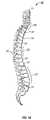
- FIG. 1 ais a longitudinal side view of a human spinal column.
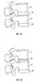
- FIG. 1 bis a detailed side view of two human vertebrae having a disk disposed between the two vertebrae.
- FIG. 1 cis a detailed side view of two human vertebrae with a bone graft disposed between two vertebrae.
- FIG. 2is a schematic showing the radius of curvature of a longitudinal curve.
- FIG. 3 ais a longitudinal side view of a prior art bone compression device before being formed into its implantation shape.
- FIG. 3 bis a longitudinal side view of the prior art bone compression device shown in FIG. 3 a in its implantation shape.
- FIG. 4is a longitudinal side view of a specific embodiment of the bone compression device of the present invention.
- FIG. 5is a top view of the bone compression device shown in FIG. 4 .
- FIG. 6is a longitudinal side view of another specific embodiment of the bone compression device of the present invention.
- FIG. 7is a top view of the bone compression device shown in FIG. 6 .
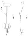
- FIG. 8is a side view of a specific embodiment of the tensioner of one specific embodiment of the bone compression system of the present invention.
- FIG. 9is a side view of a specific embodiment of the string of one specific embodiment of the bone compression system of the present invention.
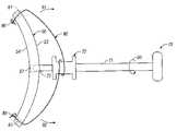
- FIG. 10is side view of one specific embodiment of the bone compression system of the present invention.
- the present inventionis directed to bone compression devices and bone compression systems for maintaining at least one bone in a desired spatial relationship. While the description of the bone compression devices, bone compression systems, and methods of contouring the bone compression devices will be directed to use in connection with two or more vertebrae, it is to be understood that the bone compression devices, bone compression systems, methods of maintaining at least two vertebrae in a spatial relationship with each other, and methods of contouring the bone compression devices of the invention may be used, or performed, in connection with any bone in which it is desired to maintain, or place, at least one bone in a desired spatial relationship, e.g., the pelvis, the femur, the fibula, the tibia, humerus, ulna, radius, or any other bone.
- a desired spatial relationshipe.g., the pelvis, the femur, the fibula, the tibia, humerus, ulna, radius, or any other bone.
- the bone compression devices of the inventionmay be employed in long bone, e.g., femur, and pelvic fracture fixation.
- the bone compression devicemay be used in connection with rigid locked screw-plates and screw-plates that permit some screw subsidence or angulation, both of which are bone compression devices known in the art.
- the bone compression devicesare utilized to maintain one or more vertebrae, and more preferably, three or more vertebrae, of the spine, and in particular, the cervical vertebrae of humans, in a desired spatial relationship.
- one or more bone graftsprior to the installation of the bone compression device, are generally disposed between two or more vertebrae. As illustrated in FIGS.
- a bone graft 28e.g., a portion of the patients' own bone, an allograft (portion of bone donated from another individual), or synthetic bone grafts or cages or boxes such as those made from carbon fiber, metal (particularly titanium), or ceramics, is usually disposed in the space created by the removal of the disk 26 .
- the bone compression devices of the inventionare installed and secured to at least the vertebra 21 disposed above the graft and the vertebra 21 disposed below the graft. Accordingly, bone graft 28 is compressed between the two vertebrae 21 to maintain bone graft 28 in a spatial relationship with vertebrae 21 .
- the bone compression devices of the inventionare suitable for fusing, e.g., being secured to, more than three vertebrae having one or more grafts disposed between two or more of the vertebrae. Therefore, in these embodiments, the vertebrae in proximity to the removed disk(s) are maintained in a desired spatial relationship to one another. Therefore, the vertebrae are permitted to heal, and, in some cases, the synthetic bone graft is permitted to be incorporated into the vertebrae using bone growth factors and other biologically active substances to facilitate the growth of bone over the synthetic bone graft.
- spine 20includes vertebrae 21 and has posterior side 23 and anterior side 24 .
- Spine 20includes numerous bone radius of curvatures 22 along the longitudinal length of spine 20 .
- bone radius of curvatures 22are identified along anterior side 24 of spine 20 .
- the bone compression devices of the inventionmay be installed, or implanted, along the posterior side 23 of spine 20 , generally, bone compression devices are implanted along anterior side 24 of spine 20 .
- Radius of curvatureis measured by determining the radius of a circle formed by the longitudinal curve of the bone (bone radius of curvature) or bone compression device (pre-formed radius of curvature, deformed radius of curvature, and elastic radius of curvature) placed along the circumference of the circle formed by the longitudinal curve of the bone or bone compression device. Accordingly, the larger the circle formed by the longitudinal curve of the bone or bone compression device, the larger the corresponding curvature, i.e., the greater the radius of curvature. Therefore, as the longitudinal curve approaches a straight line, the radius of curvature approaches infinity.
- FIG. 2illustrates how radius of curvature R is determined along curvature L with respect to circle A having center C.
- one prior bone compression device 10includes plate 11 having longitudinal length 13 .
- plateis generally straight. As such, it must be manipulated, e.g., bent, to correspond to the shape of the bone to which it will be implanted. In other words, bone compression device 10 must be manipulated to correspond to the bone radius of curvature.
- plate 10is bent in the direction of arrows 12 and 14 to create the desired radius of curvature.
- plate 11begins to revert back to its original shape ( FIG. 3 a ) by moving in the direction of arrows 16 and 18 .
- plate 11is bent to its deformed shape, thereby weakening plate 11 .
- the present inventionis directed to bone compression device 40 having plate 50 , first end 51 , second end 52 , upper surface 53 , lower surface 54 , longitudinal axis 55 along length L of plate 50 , and lateral axis 56 along width W of plate 50 .
- Length L and Width Wmay have any measurement desired or necessary to secure bone compression device 40 the bone(s) desired to be compressed.
- Length Lmust be of a distance sufficient to permit attachment of bone compression device 40 to each vertebrae. Therefore, length L of plate 50 will be greater in embodiments in which five vertebrae are to be compressed as compared to embodiments in which only two vertebrae are to be compressed.
- Plate 50also includes at least one fastener hole 58 for receiving fastener (not shown), e.g., bone screws, bolts, etc., to facilitate securing plate 50 to the bone.
- each fastener holeis angled such that each fastener is placed through fastener holes 58 to be secured into the bone at an angle, thereby facilitating securing plate 50 to the bone.
- multiple fastener holes 58are disposed along the length L and width W of plate 50 as desired or necessary to facilitate securing plate 50 to the bone.
- plate 50will preferably include fastener holes 58 such that at least one fastener will be inserted and secured to each of the vertebrae. Therefore, the total number of fastener holes 58 will be dependent upon the size of plate 50 , the number of bones to be compressed, and the size of the bone(s) to be compressed.
- plate 50includes at least one fastener hole 58 disposed near first end 51 and at least one fastener hole 58 near second end 52 .
- plate 50preferably includes at least two fastener holes 58 near first end 51 and two fastener holes 58 near second end 52 .
- fastenerse.g., bone screws
- a first fastenermay be used to secure plate 50 to the bone by placing and securing the fastener through the upper right fastener hole 58 in FIG. 5 .
- a second fastenermay be used to secure plate 50 to the bone by placing and securing the fastener through the lower left fastener hole 58 in FIG. 5 .
- a third fastenermay then be used to secure plate 50 to the bone by placing and securing the fastener through the upper left fastener hole 58 in FIG. 5 .
- a fourth fastenermay be used to secure plate 50 to the bone by placing and securing the fastener through the lower right fastener hole 58 in FIG. 5 . All four fasteners may then be tightened as necessary to secure plate 50 to the bone.
- plate 50includes plate interface, e.g., plate interface hole 57 , for receiving a tool, e.g., tensioner 70 discussed in greater detail below, to facilitate handling of plate 50 , moving plate 50 from its pre-formed shape to at least one of its at least one elastic shapes, and placement of plate 50 along the bone.
- a toole.g., tensioner 70 discussed in greater detail below
- Pre-formed radius of curvature, deformed radius of curvature, and each of the at least one elastic radius of curvature therebetweenare determined based upon the curvature of plate 50 along longitudinal axis 55 or lateral axis 56 .
- plate 50is in its pre-formed shape having pre-formed radius of curvature defined by the longitudinal curvature of lower surface 54 .
- Plate 50preferably includes at least two attachment members 59 .
- each attachment member 59is hole 61 .
- each attachment member 59is loop 62 .
- the material from which bone compression device 50 is formedmay be any material known to persons of ordinary skill in the art, the preferred material is titanium or other material having a relatively low coefficient of elasticity, thereby reducing the total number of elastic shapes bone compression device may take.
- the number of elastic shapes the bone compression device may takewill depend on the material from which bone compression device is formed. Materials having a high coefficient of elasticity will have many more elastic shapes than a material having a low coefficient of elasticity. Suitable materials include titanium, titanium-vanadium-aluminum, cobalt-chromium-molybdenum, as well as any other alloy, metal, or other material approved by the Food and Drug Administration.
- plate 50may have any two or three dimensional shape, size, or thickness desired or necessary to be sufficiently secured to one or more bones.
- plate 50preferably includes at least two attachment members, e.g., hole 61 or loop 62 , for facilitating the contouring of plate 50 , for example, by string 80 ( FIG. 9 ) and tensioner 70 .
- tensioner 70includes shaft 71 and spool 72 .
- Spool 72preferably includes a ratchet (not shown) to further facilitate winding string 80 around spool 72 and applying straightening forces to plate 50 .
- Tensioner 70also preferably includes at least one plate interface member 73 having interface member end 74 for interfacing with plate 50 , e.g., by inserting at least one plate interface member 73 into at least one corresponding plate interface hole 57 disposed along plate 50 , to further secure plate 50 to tensioner 70 thereby facilitating placement of plate 50 along the bone as well as tightening string 80 around spool 72 .
- Interface member end 74preferably is shaped to correspond with the shape of the plate interface.
- plate interface hole 57is a fastener hole 58 .
- Tensioner 70may also include handle 75 to facilitate gripping and turning tensioner 70 while tightening string 80 around spool 72 .
- string 80includes first end 81 and second end 82 and may be releasably secured to plate 50 through any manner known to persons skilled in the art.
- string 80may be passed through each attachment member 59 and tied in a knot 86 ( FIG. 10 ). Therefore, after installation of plate 50 , each knot may be cut to release plate 50 .
- first end 81 and second end 82 of string 80may include hook 64 to be passed through each attachment member 59 to secure plate 50 during installation. Thereafter, each hook 64 may be removed from each attachment member 59 thereby releasing plate 50 .
- String 80may be formed out of any material known to persons skilled in the art provided that string 80 is strong enough to withstand the tensioning forces applied to string 80 during use without breaking.
- Preferred materials for forming string 80include Kevlar and other polymers having high tensile strength.
- tensioner 70is placed in contact with plate 50 by inserting plate interface member 73 into plate interface hole 57 .
- First end 81 of string 80is passed through attachment member 59 , i.e., hole 61 in FIG. 10 , and tied into knot 86 to secure first end 81 to plate 50 .
- second end 82 of string 80is passed through attachment member 59 , i.e., hole 61 in FIG. 10 , and tied into knot 86 to secure second end 82 to plate.
- String 80is then wrapped around spool 72 of tensioner 70 .
- Tensioner 70may then be turned in the direction of arrow 90 to wind, or wrap, string 80 around spool 72 .
- string 80exerts forces on plate 50 whereby place 50 is manipulated, or moved, in the direction of arrows 91 and 92 (straightening forces) to at least one of the elastic shapes of plate 50 until the elastic radius of curvature substantially corresponds to the bone radius of curvature, i.e., the implantation shape.
- Plate 50may then be installed along one or more bones. After placement of plate 50 along one or more bones, tensioner 70 is turned in the opposite direction of arrow 90 . Therefore, due to hysteresis, plate 50 will have a tendency to move in the opposite direction of arrows 91 and 92 . In doing so, plate 50 will be further secured to the bone or bones.
- the present inventionis directed to methods of maintaining a bone in a spatial relationship, and in particular, at least two vertebrae in a spatial relationship with each other utilizing the bone compression devices discussed above.
- bone compression devicesfor maintaining two or more vertebrae is spatial relationship with each other, first, bone compression device 40 is contoured by moving bone compression device 40 from its pre-formed shape to at least one of the at least one elastic shapes corresponding to the bone radius of curvature. The bone radius of curvature is formed by the at least two vertebrae. Bone compression device 40 is then disposed along the bone radius of curvature and secured to the at least two vertebrae.
- This method of maintaining at least two vertebrae in a spatial relationship with each othermay be used in connection with the insertion of at least one bone graft between the at least two vertebrae prior to securing the bone compression device to the at least two vertebrae. Accordingly, the bone compression devices facilitate maintaining the bone graft between the vertebrae as well as maintaining the at least two vertebrae in a spatial relationship with each other.
- the bone compression devicesmay also be used for maintaining at least three, at least four, and at least five vertebrae in a spatial relationship with each other. Another feature of the method of maintaining at least two vertebrae in a spatial relationship with each other.
- bone compression device 40includes four fastener holes 58 ( FIGS. 4–7 ).
- the first fastener hole 58 , 101 near first end 51(upper left in FIGS. 5 and 7 ) is disposed diagonally from fourth fastener hole 58 , 104 near second end 52 (lower right in FIGS. 5 and 7 ) and second fastener hole 58 , 102 near first end 51 (upper right in FIGS. 5 and 7 ) is disposed diagonally from third fastener hole 58 , 103 near second end 52 (lower left in FIGS.
- a first fasteneris then inserted through first fastener hole 58 , 101 and first end 51 of plate 50 is secured to the bone (one of the at least one vertebrae).
- a second fasteneris then inserted through fourth fastener hole 58 , 104 and second end 52 of plate 50 is secured to the bone (one of the at least one vertebrae).
- First end 51 of plate 50is then further secured to the bone (one of the at least two vertebrae) with a third fastener inserted through second fastener hole 58 , 102 , and second end 52 of plate 50 is further secured to the bone (one of the at least two vertebrae) with a fourth fastener inserted through the third fastener hole 58 , 103 . It is believed that by inserting the fasteners through the fastener holes 58 to secure plate 50 to the bone in this manner, torsional resistence is lessened, thereby increasing the likelihood that bone compression device 40 will not be loosened over time.
- the inventionis not limited to the exact details of construction, operation, exact materials, or embodiments shown and described, as obvious modifications and equivalents will be apparent to one skilled in the art.
- the bone compression device illustrated and described aboveis discussed in connection with vertebrae, it may be used to with any other individual bone or bones.
- the dimensions and shapes, as well as the means for attaching the bone compression device to any bone, or number of bones,can be easily determined by a person of ordinary skill in the art.
- the bone compression deviceshave been described as being installed on the anterior side of the spine or other bone, the bone compression devices may be installed on the posterior side of the spine or other bone.
- the bone compression devicesmay be installed on any vertebrae, i.e., lumbar, thoracic, cervical, or sacral.
- the lower surface of the platemay include projections, or spikes, to facilitate securing the plate to the bone.
- the plate interface member and corresponding plate interfacemay be any shape desired or necessary to permit the plate interface to securely capture the plate interface and thus permit manipulation and placement of the plate during installation of the plate.
- the bone compression devicemay lack a distinguishable longitudinal axis, e.g., have a squared shape, or have the pre-formed, deformed, and elastic radii of curvature disposed along the width or lateral axis instead of the length or longitudinal axis. Accordingly, the invention is therefore to be limited only by the scope of the appended claims.
Landscapes
- Health & Medical Sciences (AREA)
- Orthopedic Medicine & Surgery (AREA)
- Life Sciences & Earth Sciences (AREA)
- Surgery (AREA)
- Medical Informatics (AREA)
- Engineering & Computer Science (AREA)
- Biomedical Technology (AREA)
- Heart & Thoracic Surgery (AREA)
- Nuclear Medicine, Radiotherapy & Molecular Imaging (AREA)
- Molecular Biology (AREA)
- Animal Behavior & Ethology (AREA)
- General Health & Medical Sciences (AREA)
- Public Health (AREA)
- Veterinary Medicine (AREA)
- Neurology (AREA)
- Prostheses (AREA)
- Surgical Instruments (AREA)
Abstract
Description
Claims (11)
Priority Applications (5)
| Application Number | Priority Date | Filing Date | Title |
|---|---|---|---|
| US10/273,853US7115129B2 (en) | 2001-10-19 | 2002-10-17 | Bone compression devices and systems and methods of contouring and using same |
| US10/779,980US20040172040A1 (en) | 2001-10-19 | 2004-02-17 | Bone compression devices and systems and methods of contouring and using same |
| US11/428,693US20060293671A1 (en) | 2001-10-19 | 2006-07-05 | Bone compression device |
| US12/241,512US7931679B2 (en) | 2001-10-19 | 2008-09-30 | Bone compression device |
| US13/075,550US9005251B2 (en) | 2001-10-19 | 2011-03-30 | Bone compression device |
Applications Claiming Priority (2)
| Application Number | Priority Date | Filing Date | Title |
|---|---|---|---|
| US34498001P | 2001-10-19 | 2001-10-19 | |
| US10/273,853US7115129B2 (en) | 2001-10-19 | 2002-10-17 | Bone compression devices and systems and methods of contouring and using same |
Related Child Applications (3)
| Application Number | Title | Priority Date | Filing Date |
|---|---|---|---|
| US10/779,980Continuation-In-PartUS20040172040A1 (en) | 2001-10-19 | 2004-02-17 | Bone compression devices and systems and methods of contouring and using same |
| US11/428,693DivisionUS20060293671A1 (en) | 2001-10-19 | 2006-07-05 | Bone compression device |
| US11/428,693ContinuationUS20060293671A1 (en) | 2001-10-19 | 2006-07-05 | Bone compression device |
Publications (2)
| Publication Number | Publication Date |
|---|---|
| US20030078582A1 US20030078582A1 (en) | 2003-04-24 |
| US7115129B2true US7115129B2 (en) | 2006-10-03 |
Family
ID=23352931
Family Applications (4)
| Application Number | Title | Priority Date | Filing Date |
|---|---|---|---|
| US10/273,853Expired - Fee RelatedUS7115129B2 (en) | 2001-10-19 | 2002-10-17 | Bone compression devices and systems and methods of contouring and using same |
| US11/428,693AbandonedUS20060293671A1 (en) | 2001-10-19 | 2006-07-05 | Bone compression device |
| US12/241,512Expired - Fee RelatedUS7931679B2 (en) | 2001-10-19 | 2008-09-30 | Bone compression device |
| US13/075,550Expired - Fee RelatedUS9005251B2 (en) | 2001-10-19 | 2011-03-30 | Bone compression device |
Family Applications After (3)
| Application Number | Title | Priority Date | Filing Date |
|---|---|---|---|
| US11/428,693AbandonedUS20060293671A1 (en) | 2001-10-19 | 2006-07-05 | Bone compression device |
| US12/241,512Expired - Fee RelatedUS7931679B2 (en) | 2001-10-19 | 2008-09-30 | Bone compression device |
| US13/075,550Expired - Fee RelatedUS9005251B2 (en) | 2001-10-19 | 2011-03-30 | Bone compression device |
Country Status (6)
| Country | Link |
|---|---|
| US (4) | US7115129B2 (en) |
| EP (1) | EP1435857B1 (en) |
| JP (1) | JP4399263B2 (en) |
| AU (1) | AU2002349962B2 (en) |
| CA (1) | CA2463513C (en) |
| WO (1) | WO2003032848A2 (en) |
Cited By (72)
| Publication number | Priority date | Publication date | Assignee | Title |
|---|---|---|---|---|
| US20070239158A1 (en)* | 2006-04-10 | 2007-10-11 | Sdgi Holdings, Inc. | Elastic plates for spinal fixation or stabilization |
| US20080140075A1 (en)* | 2006-12-07 | 2008-06-12 | Ensign Michael D | Press-On Pedicle Screw Assembly |
| US20080195213A1 (en)* | 2007-02-12 | 2008-08-14 | Brigham Young University | Spinal implant |
| US20090024171A1 (en)* | 2007-07-19 | 2009-01-22 | Vincent Leone | Anatomical Anterior Vertebral Plating System |
| WO2009091770A1 (en) | 2008-01-17 | 2009-07-23 | Warsaw Orthopedic, Inc. | Spinal osteosynthesis device |
| US20100211106A1 (en)* | 2009-02-19 | 2010-08-19 | Bowden Anton E | Compliant Dynamic Spinal Implant And Associated Methods |
| US20100217334A1 (en)* | 2009-02-23 | 2010-08-26 | Hawkes David T | Press-On Link For Surgical Screws |
| US20100241232A1 (en)* | 2007-02-12 | 2010-09-23 | Peter Halverson | Spinal implant |
| US7959679B2 (en) | 1999-08-18 | 2011-06-14 | Intrinsic Therapeutics, Inc. | Intervertebral anulus and nucleus augmentation |
| US7972337B2 (en) | 2005-12-28 | 2011-07-05 | Intrinsic Therapeutics, Inc. | Devices and methods for bone anchoring |
| US20110178555A1 (en)* | 2001-10-19 | 2011-07-21 | Baylor College Of Medicine | Bone compression device |
| US8002836B2 (en) | 1999-08-18 | 2011-08-23 | Intrinsic Therapeutics, Inc. | Method for the treatment of the intervertebral disc anulus |
| US8021425B2 (en)* | 1999-08-18 | 2011-09-20 | Intrinsic Therapeutics, Inc. | Versatile method of repairing an intervertebral disc |
| US8066750B2 (en) | 2006-10-06 | 2011-11-29 | Warsaw Orthopedic, Inc | Port structures for non-rigid bone plates |
| US8231678B2 (en) | 1999-08-18 | 2012-07-31 | Intrinsic Therapeutics, Inc. | Method of treating a herniated disc |
| US8298242B2 (en) | 2010-04-30 | 2012-10-30 | Warsaw Orthopedic, Inc. | Systems, devices and methods for bending an elongate member |
| US8323341B2 (en) | 2007-09-07 | 2012-12-04 | Intrinsic Therapeutics, Inc. | Impaction grafting for vertebral fusion |
| US8454612B2 (en) | 2007-09-07 | 2013-06-04 | Intrinsic Therapeutics, Inc. | Method for vertebral endplate reconstruction |
| US8607603B2 (en) | 2010-04-30 | 2013-12-17 | Warsaw Orthopedic, Inc. | Systems, devices and methods for multi-dimensional bending of an elongate member |
| US8894687B2 (en) | 2011-04-25 | 2014-11-25 | Nexus Spine, L.L.C. | Coupling system for surgical construct |
| US8992579B1 (en) | 2011-03-08 | 2015-03-31 | Nuvasive, Inc. | Lateral fixation constructs and related methods |
| US9060815B1 (en) | 2012-03-08 | 2015-06-23 | Nuvasive, Inc. | Systems and methods for performing spine surgery |
| US9157497B1 (en) | 2009-10-30 | 2015-10-13 | Brigham Young University | Lamina emergent torsional joint and related methods |
| US9204932B2 (en) | 2012-02-16 | 2015-12-08 | Biomedical Enterprises, Inc. | Apparatus for an orthopedic fixation system |
| US9333008B2 (en) | 2010-02-19 | 2016-05-10 | Brigham Young University | Serpentine spinal stability device |
| US9408647B2 (en) | 2014-02-27 | 2016-08-09 | Biomedical Enterprises, Inc. | Method and apparatus for use of a compressing plate |
| US9517089B1 (en) | 2013-10-08 | 2016-12-13 | Nuvasive, Inc. | Bone anchor with offset rod connector |
| US9642651B2 (en) | 2014-06-12 | 2017-05-09 | Brigham Young University | Inverted serpentine spinal stability device and associated methods |
| US9706947B2 (en) | 1999-08-18 | 2017-07-18 | Intrinsic Therapeutics, Inc. | Method of performing an anchor implantation procedure within a disc |
| US9883897B2 (en) | 2014-09-25 | 2018-02-06 | Biomedical Enterprises, Inc. | Method and apparatus for a compressing plate |
| US10016220B2 (en) | 2011-11-01 | 2018-07-10 | Nuvasive Specialized Orthopedics, Inc. | Adjustable magnetic devices and methods of using same |
| US10039661B2 (en) | 2006-10-20 | 2018-08-07 | Nuvasive Specialized Orthopedics, Inc. | Adjustable implant and method of use |
| US10238427B2 (en) | 2015-02-19 | 2019-03-26 | Nuvasive Specialized Orthopedics, Inc. | Systems and methods for vertebral adjustment |
| US10271885B2 (en) | 2014-12-26 | 2019-04-30 | Nuvasive Specialized Orthopedics, Inc. | Systems and methods for distraction |
| US10349995B2 (en) | 2007-10-30 | 2019-07-16 | Nuvasive Specialized Orthopedics, Inc. | Skeletal manipulation method |
| US10405891B2 (en) | 2010-08-09 | 2019-09-10 | Nuvasive Specialized Orthopedics, Inc. | Maintenance feature in magnetic implant |
| US10405935B2 (en) | 2017-04-05 | 2019-09-10 | Warsaw Orthopedic, Inc. | Surgical implant bending system and method |
| US10478232B2 (en) | 2009-04-29 | 2019-11-19 | Nuvasive Specialized Orthopedics, Inc. | Interspinous process device and method |
| US10517643B2 (en) | 2009-02-23 | 2019-12-31 | Nuvasive Specialized Orthopedics, Inc. | Non-invasive adjustable distraction system |
| US10524846B2 (en) | 2017-04-05 | 2020-01-07 | Warsaw Orthopedic, Inc. | Surgical implant bending system and method |
| US10582968B2 (en) | 2017-04-04 | 2020-03-10 | Warsaw Orthopedic, Inc. | Surgical implant bending system and method |
| US10617453B2 (en) | 2015-10-16 | 2020-04-14 | Nuvasive Specialized Orthopedics, Inc. | Adjustable devices for treating arthritis of the knee |
| US10646259B2 (en) | 2017-04-05 | 2020-05-12 | Warsaw Orthopedic, Inc. | Surgical implant bending system and method |
| US10646262B2 (en) | 2011-02-14 | 2020-05-12 | Nuvasive Specialized Orthopedics, Inc. | System and method for altering rotational alignment of bone sections |
| US10660675B2 (en) | 2010-06-30 | 2020-05-26 | Nuvasive Specialized Orthopedics, Inc. | External adjustment device for distraction device |
| US10729470B2 (en) | 2008-11-10 | 2020-08-04 | Nuvasive Specialized Orthopedics, Inc. | External adjustment device for distraction device |
| US10743794B2 (en) | 2011-10-04 | 2020-08-18 | Nuvasive Specialized Orthopedics, Inc. | Devices and methods for non-invasive implant length sensing |
| US10751094B2 (en) | 2013-10-10 | 2020-08-25 | Nuvasive Specialized Orthopedics, Inc. | Adjustable spinal implant |
| US10835290B2 (en) | 2015-12-10 | 2020-11-17 | Nuvasive Specialized Orthopedics, Inc. | External adjustment device for distraction device |
| US10918425B2 (en) | 2016-01-28 | 2021-02-16 | Nuvasive Specialized Orthopedics, Inc. | System and methods for bone transport |
| US20210220029A1 (en)* | 2015-03-03 | 2021-07-22 | Pioneer Surgical Technology, Inc. | Bone compression device and method |
| US11191579B2 (en) | 2012-10-29 | 2021-12-07 | Nuvasive Specialized Orthopedics, Inc. | Adjustable devices for treating arthritis of the knee |
| US11202707B2 (en) | 2008-03-25 | 2021-12-21 | Nuvasive Specialized Orthopedics, Inc. | Adjustable implant system |
| US11207110B2 (en) | 2009-09-04 | 2021-12-28 | Nuvasive Specialized Orthopedics, Inc. | Bone growth device and method |
| US11246694B2 (en) | 2014-04-28 | 2022-02-15 | Nuvasive Specialized Orthopedics, Inc. | System for informational magnetic feedback in adjustable implants |
| USRE49061E1 (en) | 2012-10-18 | 2022-05-10 | Nuvasive Specialized Orthopedics, Inc. | Intramedullary implants for replacing lost bone |
| US11357549B2 (en) | 2004-07-02 | 2022-06-14 | Nuvasive Specialized Orthopedics, Inc. | Expandable rod system to treat scoliosis and method of using the same |
| US11357547B2 (en) | 2014-10-23 | 2022-06-14 | Nuvasive Specialized Orthopedics Inc. | Remotely adjustable interactive bone reshaping implant |
| US11577097B2 (en) | 2019-02-07 | 2023-02-14 | Nuvasive Specialized Orthopedics, Inc. | Ultrasonic communication in medical devices |
| US11589901B2 (en) | 2019-02-08 | 2023-02-28 | Nuvasive Specialized Orthopedics, Inc. | External adjustment device |
| US11696836B2 (en) | 2013-08-09 | 2023-07-11 | Nuvasive, Inc. | Lordotic expandable interbody implant |
| US11737787B1 (en) | 2021-05-27 | 2023-08-29 | Nuvasive, Inc. | Bone elongating devices and methods of use |
| US20230293211A1 (en)* | 2022-03-21 | 2023-09-21 | Ryan J. Niver | Bone fixation systems and methods for fixating bones |
| US11766252B2 (en) | 2013-07-31 | 2023-09-26 | Nuvasive Specialized Orthopedics, Inc. | Noninvasively adjustable suture anchors |
| US11801187B2 (en) | 2016-02-10 | 2023-10-31 | Nuvasive Specialized Orthopedics, Inc. | Systems and methods for controlling multiple surgical variables |
| US11806059B2 (en) | 2020-07-14 | 2023-11-07 | DePuy Synthes Products, Inc. | Shape memory implants and methods and apparatus for the loading and implanting thereof |
| US11806054B2 (en) | 2021-02-23 | 2023-11-07 | Nuvasive Specialized Orthopedics, Inc. | Adjustable implant, system and methods |
| US11839410B2 (en) | 2012-06-15 | 2023-12-12 | Nuvasive Inc. | Magnetic implants with improved anatomical compatibility |
| US11857226B2 (en) | 2013-03-08 | 2024-01-02 | Nuvasive Specialized Orthopedics | Systems and methods for ultrasonic detection of device distraction |
| US11925389B2 (en) | 2008-10-13 | 2024-03-12 | Nuvasive Specialized Orthopedics, Inc. | Spinal distraction system |
| US12023073B2 (en) | 2021-08-03 | 2024-07-02 | Nuvasive Specialized Orthopedics, Inc. | Adjustable implant |
| US12213708B2 (en) | 2020-09-08 | 2025-02-04 | Nuvasive Specialized Orthopedics, Inc. | Remote control module for adjustable implants |
Families Citing this family (14)
| Publication number | Priority date | Publication date | Assignee | Title |
|---|---|---|---|---|
| US8870920B2 (en)* | 2005-10-07 | 2014-10-28 | M. Samy Abdou | Devices and methods for inter-vertebral orthopedic device placement |
| US8133283B2 (en)* | 2007-06-06 | 2012-03-13 | Kenneth Mitchell Wilson | Scapho-lunate fixation implants and methods of use |
| US8888826B2 (en)* | 2008-11-20 | 2014-11-18 | Mbrace, Llc | Surgical device, system and method of use thereof |
| WO2012048131A2 (en)* | 2010-10-06 | 2012-04-12 | Simpirica Spine, Inc. | Device and accessories for limiting flexion |
| EP3326558B1 (en) | 2011-11-14 | 2025-04-30 | The University of British Columbia | Intramedullary fixation system for management of pelvic and acetabular fractures |
| KR20140119797A (en) | 2012-03-01 | 2014-10-10 | 솔라나 서지컬, 엘엘씨 | Surgical staple for insertion into bones |
| US20150105834A1 (en)* | 2013-10-11 | 2015-04-16 | Ellipse Technologies, Inc. | Methods and apparatus for bone reshaping |
| WO2015134750A1 (en) | 2014-03-06 | 2015-09-11 | University Of British Columbia | Shape adaptable intramedullary fixation device |
| JP6389002B2 (en) | 2014-10-14 | 2018-09-12 | ザ ユニヴァーシティ オブ ブリティッシュ コロンビア | System and method for intramedullary bone fixation |
| EP3522803A4 (en) | 2016-10-05 | 2020-05-27 | The University of British Columbia | Intramedullary fixation device with shape locking interface |
| CN112367937A (en) | 2018-06-29 | 2021-02-12 | 先锋外科技术公司 | Bone plating system |
| CN112912022A (en) | 2018-10-17 | 2021-06-04 | 不列颠哥伦比亚大学 | Bone fixation device and system |
| US11877779B2 (en) | 2020-03-26 | 2024-01-23 | Xtant Medical Holdings, Inc. | Bone plate system |
| US11931084B2 (en) | 2021-12-07 | 2024-03-19 | DePuy Synthes Products, Inc. | Method and apparatus for an orthopedic fixation system |
Citations (32)
| Publication number | Priority date | Publication date | Assignee | Title |
|---|---|---|---|---|
| US4219015A (en)* | 1977-04-22 | 1980-08-26 | Institut Straumann Ag | Plates for osteosynthesis |
| US4263904A (en)* | 1978-02-10 | 1981-04-28 | Judet Robert L | Osteosynthesis devices |
| US4651724A (en)* | 1984-05-18 | 1987-03-24 | Technomed Gmk | Bone joining plate |
| US4683878A (en)* | 1985-04-29 | 1987-08-04 | Kirschner Medical Corporation | Osteosynthetic fixation plate |
| US5053036A (en)* | 1987-11-03 | 1991-10-01 | Synthes (U.S.A.) | Point contact bone compression plate |
| US5147361A (en) | 1989-11-29 | 1992-09-15 | Asahi Kogaku Kogyo Kabushiki Kaisha | Vertebral connecting plate |
| US5180381A (en) | 1991-09-24 | 1993-01-19 | Aust Gilbert M | Anterior lumbar/cervical bicortical compression plate |
| US5246443A (en)* | 1990-10-30 | 1993-09-21 | Christian Mai | Clip and osteosynthesis plate with dynamic compression and self-retention |
| US5298115A (en) | 1989-11-09 | 1994-03-29 | Ian Leonard | Producing prostheses |
| US5364399A (en) | 1993-02-05 | 1994-11-15 | Danek Medical, Inc. | Anterior cervical plating system |
| US5423826A (en) | 1993-02-05 | 1995-06-13 | Danek Medical, Inc. | Anterior cervical plate holder/drill guide and method of use |
| US5549612A (en) | 1992-11-25 | 1996-08-27 | Codman & Shurtleff, Inc. | Osteosynthesis plate system |
| US5601553A (en)* | 1994-10-03 | 1997-02-11 | Synthes (U.S.A.) | Locking plate and bone screw |
| US5603713A (en) | 1991-09-24 | 1997-02-18 | Aust; Gilbert M. | Anterior lumbar/cervical bicortical compression plate |
| US5620443A (en) | 1995-01-25 | 1997-04-15 | Danek Medical, Inc. | Anterior screw-rod connector |
| US5662655A (en) | 1992-07-24 | 1997-09-02 | Laboureau; Jacques Philippe | Osteosynthesis plate-staple |
| US5843082A (en) | 1996-05-31 | 1998-12-01 | Acromed Corporation | Cervical spine stabilization method and system |
| US5904683A (en) | 1998-07-10 | 1999-05-18 | Sulzer Spine-Tech Inc. | Anterior cervical vertebral stabilizing device |
| USRE36221E (en) | 1989-02-03 | 1999-06-01 | Breard; Francis Henri | Flexible inter-vertebral stabilizer as well as process and apparatus for determining or verifying its tension before installation on the spinal column |
| US5951557A (en)* | 1997-12-30 | 1999-09-14 | Luter; Dennis W. | Bone plate |
| US6059787A (en)* | 1999-04-26 | 2000-05-09 | Allen; Drew | Compression bone staple apparatus and method |
| US6139550A (en) | 1997-02-11 | 2000-10-31 | Michelson; Gary K. | Skeletal plating system |
| US6139551A (en) | 1995-06-07 | 2000-10-31 | Sdgi Holdings, Inc. | Anterior spinal instrumentation and method for implantation and revision |
| US6152927A (en) | 1997-05-15 | 2000-11-28 | Sdgi Holdings, Inc. | Anterior cervical plating system |
| US6193721B1 (en) | 1997-02-11 | 2001-02-27 | Gary K. Michelson | Multi-lock anterior cervical plating system |
| US6193720B1 (en) | 1998-11-30 | 2001-02-27 | Depuy Orthopaedics, Inc. | Cervical spine stabilization method and system |
| US6214006B1 (en) | 1992-03-02 | 2001-04-10 | Howmedica Gmbh | Apparatus for bracing vertebrae |
| WO2001026566A1 (en) | 1999-10-13 | 2001-04-19 | Sdgi Holdings, Inc. | Anterior cervical plating system and method |
| US6228085B1 (en) | 1998-07-14 | 2001-05-08 | Theken Surgical Llc | Bone fixation system |
| US6248106B1 (en) | 2000-02-25 | 2001-06-19 | Bret Ferree | Cross-coupled vertebral stabilizers |
| US6273889B1 (en) | 1997-05-09 | 2001-08-14 | Spinal Innovations, Llc | Method of fixing a spine with a fixation plate |
| US6293949B1 (en)* | 2000-03-01 | 2001-09-25 | Sdgi Holdings, Inc. | Superelastic spinal stabilization system and method |
Family Cites Families (7)
| Publication number | Priority date | Publication date | Assignee | Title |
|---|---|---|---|---|
| US2002021A (en)* | 1934-02-27 | 1935-05-21 | Rouse Howard | Surgical fracture extension appliance |
| US3328738A (en)* | 1965-04-23 | 1967-06-27 | Westinghouse Electric Corp | Five-legged magnetic core structures and windings which produce flux in quadrature |
| US3446212A (en)* | 1965-07-19 | 1969-05-27 | New Research & Dev Lab Inc | Hemostatic clip and applicator therefor |
| US3960147A (en)* | 1975-03-10 | 1976-06-01 | Murray William M | Compression bone staples and methods of compressing bone segments |
| US5474553A (en)* | 1989-04-18 | 1995-12-12 | Rainer Baumgart | System for setting tubular bone fractures |
| GB9110778D0 (en)* | 1991-05-18 | 1991-07-10 | Middleton Jeffrey K | Apparatus for use in surgery |
| AU2002349962B2 (en)* | 2001-10-19 | 2006-04-06 | Baylor College Of Medicine | Bone compression devices and systems and methods of contouring and using same |
- 2002
- 2002-10-17AUAU2002349962Apatent/AU2002349962B2/ennot_activeCeased
- 2002-10-17CACA 2463513patent/CA2463513C/ennot_activeExpired - Fee Related
- 2002-10-17USUS10/273,853patent/US7115129B2/ennot_activeExpired - Fee Related
- 2002-10-17EPEP02786442.0Apatent/EP1435857B1/ennot_activeExpired - Lifetime
- 2002-10-17JPJP2003535656Apatent/JP4399263B2/ennot_activeExpired - Fee Related
- 2002-10-17WOPCT/US2002/033380patent/WO2003032848A2/enactiveApplication Filing
- 2006
- 2006-07-05USUS11/428,693patent/US20060293671A1/ennot_activeAbandoned
- 2008
- 2008-09-30USUS12/241,512patent/US7931679B2/ennot_activeExpired - Fee Related
- 2011
- 2011-03-30USUS13/075,550patent/US9005251B2/ennot_activeExpired - Fee Related
Patent Citations (40)
| Publication number | Priority date | Publication date | Assignee | Title |
|---|---|---|---|---|
| US4219015A (en)* | 1977-04-22 | 1980-08-26 | Institut Straumann Ag | Plates for osteosynthesis |
| US4263904A (en)* | 1978-02-10 | 1981-04-28 | Judet Robert L | Osteosynthesis devices |
| US4651724A (en)* | 1984-05-18 | 1987-03-24 | Technomed Gmk | Bone joining plate |
| US4683878A (en)* | 1985-04-29 | 1987-08-04 | Kirschner Medical Corporation | Osteosynthetic fixation plate |
| US5053036A (en)* | 1987-11-03 | 1991-10-01 | Synthes (U.S.A.) | Point contact bone compression plate |
| USRE36221E (en) | 1989-02-03 | 1999-06-01 | Breard; Francis Henri | Flexible inter-vertebral stabilizer as well as process and apparatus for determining or verifying its tension before installation on the spinal column |
| US5298115A (en) | 1989-11-09 | 1994-03-29 | Ian Leonard | Producing prostheses |
| US5147361A (en) | 1989-11-29 | 1992-09-15 | Asahi Kogaku Kogyo Kabushiki Kaisha | Vertebral connecting plate |
| US5246443A (en)* | 1990-10-30 | 1993-09-21 | Christian Mai | Clip and osteosynthesis plate with dynamic compression and self-retention |
| US5180381A (en) | 1991-09-24 | 1993-01-19 | Aust Gilbert M | Anterior lumbar/cervical bicortical compression plate |
| US5603713A (en) | 1991-09-24 | 1997-02-18 | Aust; Gilbert M. | Anterior lumbar/cervical bicortical compression plate |
| US20010020169A1 (en) | 1992-03-02 | 2001-09-06 | Peter Metz-Stavenhagen | Apparatus for bracing vertebrae |
| US6214006B1 (en) | 1992-03-02 | 2001-04-10 | Howmedica Gmbh | Apparatus for bracing vertebrae |
| US5662655A (en) | 1992-07-24 | 1997-09-02 | Laboureau; Jacques Philippe | Osteosynthesis plate-staple |
| US5549612A (en) | 1992-11-25 | 1996-08-27 | Codman & Shurtleff, Inc. | Osteosynthesis plate system |
| US5423826A (en) | 1993-02-05 | 1995-06-13 | Danek Medical, Inc. | Anterior cervical plate holder/drill guide and method of use |
| US5364399A (en) | 1993-02-05 | 1994-11-15 | Danek Medical, Inc. | Anterior cervical plating system |
| US5601553A (en)* | 1994-10-03 | 1997-02-11 | Synthes (U.S.A.) | Locking plate and bone screw |
| US5620443A (en) | 1995-01-25 | 1997-04-15 | Danek Medical, Inc. | Anterior screw-rod connector |
| US20010010000A1 (en) | 1995-01-25 | 2001-07-26 | Stanley Gertzbein | Spinal rod transverse connectors |
| US6254603B1 (en) | 1995-01-25 | 2001-07-03 | Sdgi Holdings, Inc. | Spinal rod transverse connectors |
| US6066140A (en) | 1995-01-25 | 2000-05-23 | Sdgi Holdings, Inc. | Spinal rod transverse connectors |
| US6083224A (en) | 1995-01-25 | 2000-07-04 | Sdgi Holdings, Inc. | Dynamic spinal screw-rod connectors |
| USRE37161E1 (en) | 1995-06-07 | 2001-05-01 | Gary Karlin Michelson | Anterior spinal instrumentation and method for implantation and revision |
| US6139551A (en) | 1995-06-07 | 2000-10-31 | Sdgi Holdings, Inc. | Anterior spinal instrumentation and method for implantation and revision |
| US6190388B1 (en) | 1995-06-07 | 2001-02-20 | Gary K. Michelson | Anterior spinal instrumentation and method for implantation and revision |
| US5843082A (en) | 1996-05-31 | 1998-12-01 | Acromed Corporation | Cervical spine stabilization method and system |
| US6036693A (en) | 1996-05-31 | 2000-03-14 | Depuy Orthopaedics, Inc. | Cervical spine stabilization method and system |
| US6193721B1 (en) | 1997-02-11 | 2001-02-27 | Gary K. Michelson | Multi-lock anterior cervical plating system |
| US6139550A (en) | 1997-02-11 | 2000-10-31 | Michelson; Gary K. | Skeletal plating system |
| US6273889B1 (en) | 1997-05-09 | 2001-08-14 | Spinal Innovations, Llc | Method of fixing a spine with a fixation plate |
| US6152927A (en) | 1997-05-15 | 2000-11-28 | Sdgi Holdings, Inc. | Anterior cervical plating system |
| US5951557A (en)* | 1997-12-30 | 1999-09-14 | Luter; Dennis W. | Bone plate |
| US5904683A (en) | 1998-07-10 | 1999-05-18 | Sulzer Spine-Tech Inc. | Anterior cervical vertebral stabilizing device |
| US6228085B1 (en) | 1998-07-14 | 2001-05-08 | Theken Surgical Llc | Bone fixation system |
| US6193720B1 (en) | 1998-11-30 | 2001-02-27 | Depuy Orthopaedics, Inc. | Cervical spine stabilization method and system |
| US6059787A (en)* | 1999-04-26 | 2000-05-09 | Allen; Drew | Compression bone staple apparatus and method |
| WO2001026566A1 (en) | 1999-10-13 | 2001-04-19 | Sdgi Holdings, Inc. | Anterior cervical plating system and method |
| US6248106B1 (en) | 2000-02-25 | 2001-06-19 | Bret Ferree | Cross-coupled vertebral stabilizers |
| US6293949B1 (en)* | 2000-03-01 | 2001-09-25 | Sdgi Holdings, Inc. | Superelastic spinal stabilization system and method |
Non-Patent Citations (9)
| Title |
|---|
| Cervical Plating System, http://www.aesculap-usa.com/whatsnew/abc<SUB>-</SUB>cps/wn<SUB>-</SUB>abc<SUB>-</SUB>cps.htm, 2 pages. |
| Chapter 21 Surgical Management of Cervical Disc Disease, The Spine, 4th Edition, 1999, pp. 497-564, W.B. Saunders Co., Philadelphia, Pennsylvania. |
| Dick, Jeffrey C., et al., Notch Sensitivity of Titanium Alloy, Commercially Pure Titanium, and Stainless Steel Spinal Implants, Spine, 2001, pp. 1668-1672, vol. 26, No. 15, Lippincott Williams & Wilkins, Inc. |
| Medline Search, 3 pages. |
| New Anterior Cervical Plate Makes Headlines, http://www.spineuniverse.com/displayarticle.php/article1535.html, 4 pages. |
| Nunamaker, David M., et al., A Radiological and Histological Analysis of Fracture Healing Using Prebending of Compression Plates, Clinical Orthopaedics and Related Research, Jan.-Feb. 1979, pp. 167-174, No. 138, J.B. Lippincott Company. |
| Nunamaker, David M., Excerpts from Chapter 16: Methods of Internal Fixation (kinda Vet's Ortho Texbook available online), http://www.cal.nbc.upenn.edu/saortho/chapter<SUB>-</SUB>16/16mast.htm#REFS, 7 pages. |
| Prebending of Plates, http://www.medmedia.com/o16/91.htm, 1 page. |
| Ramotowski, Witold, et al., Zespol An Original Method of Stable Osteosynthesis, Clinical Orthopaedics and Related Research, Nov. 1991, pp. 67-75, No. 272. |
Cited By (146)
| Publication number | Priority date | Publication date | Assignee | Title |
|---|---|---|---|---|
| US8021425B2 (en)* | 1999-08-18 | 2011-09-20 | Intrinsic Therapeutics, Inc. | Versatile method of repairing an intervertebral disc |
| US9706947B2 (en) | 1999-08-18 | 2017-07-18 | Intrinsic Therapeutics, Inc. | Method of performing an anchor implantation procedure within a disc |
| US9333087B2 (en) | 1999-08-18 | 2016-05-10 | Intrinsic Therapeutics, Inc. | Herniated disc repair |
| US8409284B2 (en) | 1999-08-18 | 2013-04-02 | Intrinsic Therapeutics, Inc. | Methods of repairing herniated segments in the disc |
| US8257437B2 (en) | 1999-08-18 | 2012-09-04 | Intrinsic Therapeutics, Inc. | Methods of intervertebral disc augmentation |
| US8231678B2 (en) | 1999-08-18 | 2012-07-31 | Intrinsic Therapeutics, Inc. | Method of treating a herniated disc |
| US8105384B2 (en) | 1999-08-18 | 2012-01-31 | Intrinsic Therapeutics, Inc. | Weakened anulus repair |
| US8025698B2 (en) | 1999-08-18 | 2011-09-27 | Intrinsic Therapeutics, Inc. | Method of rehabilitating an anulus fibrosus |
| US7959679B2 (en) | 1999-08-18 | 2011-06-14 | Intrinsic Therapeutics, Inc. | Intervertebral anulus and nucleus augmentation |
| US8002836B2 (en) | 1999-08-18 | 2011-08-23 | Intrinsic Therapeutics, Inc. | Method for the treatment of the intervertebral disc anulus |
| US7998213B2 (en) | 1999-08-18 | 2011-08-16 | Intrinsic Therapeutics, Inc. | Intervertebral disc herniation repair |
| US9005251B2 (en)* | 2001-10-19 | 2015-04-14 | Baylor College Of Medicine | Bone compression device |
| US20110178555A1 (en)* | 2001-10-19 | 2011-07-21 | Baylor College Of Medicine | Bone compression device |
| US11712268B2 (en) | 2004-07-02 | 2023-08-01 | Nuvasive Specialized Orthopedics, Inc. | Expandable rod system to treat scoliosis and method of using the same |
| US11357549B2 (en) | 2004-07-02 | 2022-06-14 | Nuvasive Specialized Orthopedics, Inc. | Expandable rod system to treat scoliosis and method of using the same |
| US9610106B2 (en) | 2005-12-28 | 2017-04-04 | Intrinsic Therapeutics, Inc. | Bone anchor systems |
| US10470804B2 (en) | 2005-12-28 | 2019-11-12 | Intrinsic Therapeutics, Inc. | Bone anchor delivery systems and methods |
| US9039741B2 (en) | 2005-12-28 | 2015-05-26 | Intrinsic Therapeutics, Inc. | Bone anchor systems |
| US11185354B2 (en) | 2005-12-28 | 2021-11-30 | Intrinsic Therapeutics, Inc. | Bone anchor delivery systems and methods |
| US8394146B2 (en) | 2005-12-28 | 2013-03-12 | Intrinsic Therapeutics, Inc. | Vertebral anchoring methods |
| US7972337B2 (en) | 2005-12-28 | 2011-07-05 | Intrinsic Therapeutics, Inc. | Devices and methods for bone anchoring |
| US8114082B2 (en) | 2005-12-28 | 2012-02-14 | Intrinsic Therapeutics, Inc. | Anchoring system for disc repair |
| US20070239158A1 (en)* | 2006-04-10 | 2007-10-11 | Sdgi Holdings, Inc. | Elastic plates for spinal fixation or stabilization |
| US8066750B2 (en) | 2006-10-06 | 2011-11-29 | Warsaw Orthopedic, Inc | Port structures for non-rigid bone plates |
| US11672684B2 (en) | 2006-10-20 | 2023-06-13 | Nuvasive Specialized Orthopedics, Inc. | Adjustable implant and method of use |
| US10039661B2 (en) | 2006-10-20 | 2018-08-07 | Nuvasive Specialized Orthopedics, Inc. | Adjustable implant and method of use |
| US11234849B2 (en) | 2006-10-20 | 2022-02-01 | Nuvasive Specialized Orthopedics, Inc. | Adjustable implant and method of use |
| US20080140075A1 (en)* | 2006-12-07 | 2008-06-12 | Ensign Michael D | Press-On Pedicle Screw Assembly |
| US9867640B2 (en) | 2006-12-07 | 2018-01-16 | Nexus Spine, LLC | Press-on pedicle screw assembly |
| US12364511B2 (en) | 2006-12-07 | 2025-07-22 | Nexus Spine, LLC | Press-on pedicle screw assembly |
| US20100241232A1 (en)* | 2007-02-12 | 2010-09-23 | Peter Halverson | Spinal implant |
| US8308801B2 (en) | 2007-02-12 | 2012-11-13 | Brigham Young University | Spinal implant |
| US20080195213A1 (en)* | 2007-02-12 | 2008-08-14 | Brigham Young University | Spinal implant |
| US9314346B2 (en) | 2007-02-12 | 2016-04-19 | Brigham Young University | Spinal implant |
| US20090024171A1 (en)* | 2007-07-19 | 2009-01-22 | Vincent Leone | Anatomical Anterior Vertebral Plating System |
| US10076424B2 (en) | 2007-09-07 | 2018-09-18 | Intrinsic Therapeutics, Inc. | Impaction systems |
| US9226832B2 (en) | 2007-09-07 | 2016-01-05 | Intrinsic Therapeutics, Inc. | Interbody fusion material retention methods |
| US10716685B2 (en) | 2007-09-07 | 2020-07-21 | Intrinsic Therapeutics, Inc. | Bone anchor delivery systems |
| US8323341B2 (en) | 2007-09-07 | 2012-12-04 | Intrinsic Therapeutics, Inc. | Impaction grafting for vertebral fusion |
| US8361155B2 (en) | 2007-09-07 | 2013-01-29 | Intrinsic Therapeutics, Inc. | Soft tissue impaction methods |
| US8454612B2 (en) | 2007-09-07 | 2013-06-04 | Intrinsic Therapeutics, Inc. | Method for vertebral endplate reconstruction |
| US10349995B2 (en) | 2007-10-30 | 2019-07-16 | Nuvasive Specialized Orthopedics, Inc. | Skeletal manipulation method |
| US11172972B2 (en) | 2007-10-30 | 2021-11-16 | Nuvasive Specialized Orthopedics, Inc. | Skeletal manipulation method |
| US11871974B2 (en) | 2007-10-30 | 2024-01-16 | Nuvasive Specialized Orthopedics, Inc. | Skeletal manipulation method |
| WO2009091770A1 (en) | 2008-01-17 | 2009-07-23 | Warsaw Orthopedic, Inc. | Spinal osteosynthesis device |
| EP2231044A4 (en)* | 2008-01-17 | 2010-12-22 | Warsaw Orthopedic Inc | Spinal osteosynthesis device |
| US11202707B2 (en) | 2008-03-25 | 2021-12-21 | Nuvasive Specialized Orthopedics, Inc. | Adjustable implant system |
| US12076241B2 (en) | 2008-03-25 | 2024-09-03 | Nuvasive Specialized Orthopedics, Inc. | Adjustable implant system |
| US11925389B2 (en) | 2008-10-13 | 2024-03-12 | Nuvasive Specialized Orthopedics, Inc. | Spinal distraction system |
| US10729470B2 (en) | 2008-11-10 | 2020-08-04 | Nuvasive Specialized Orthopedics, Inc. | External adjustment device for distraction device |
| US11974782B2 (en) | 2008-11-10 | 2024-05-07 | Nuvasive Specialized Orthopedics, Inc. | External adjustment device for distraction device |
| US8663286B2 (en) | 2009-02-19 | 2014-03-04 | Brigham Young University | Compliant dynamic spinal implant and associated methods |
| US20100222821A1 (en)* | 2009-02-19 | 2010-09-02 | Bowden Anton E | Compliant Dynamic Spinal Implant |
| US20100222823A1 (en)* | 2009-02-19 | 2010-09-02 | Bowden Anton E | Method Of Surgically Implanting A Spinal Implant |
| US20100211106A1 (en)* | 2009-02-19 | 2010-08-19 | Bowden Anton E | Compliant Dynamic Spinal Implant And Associated Methods |
| US20100217326A1 (en)* | 2009-02-19 | 2010-08-26 | Bowden Anton E | Method of Treating A Degenerate Spinal Segment |
| US8172883B2 (en) | 2009-02-19 | 2012-05-08 | Brigham Young University | Method of treating a degenerate spinal segment |
| US20100217324A1 (en)* | 2009-02-19 | 2010-08-26 | Bowden Anton E | Compliant Dynamic Spinal Implant And Associated Methods |
| US11304729B2 (en) | 2009-02-23 | 2022-04-19 | Nuvasive Specialized Orthhopedics, Inc. | Non-invasive adjustable distraction system |
| US20100217334A1 (en)* | 2009-02-23 | 2010-08-26 | Hawkes David T | Press-On Link For Surgical Screws |
| US10517643B2 (en) | 2009-02-23 | 2019-12-31 | Nuvasive Specialized Orthopedics, Inc. | Non-invasive adjustable distraction system |
| US9232965B2 (en) | 2009-02-23 | 2016-01-12 | Nexus Spine, LLC | Press-on link for surgical screws |
| US11918254B2 (en) | 2009-02-23 | 2024-03-05 | Nuvasive Specialized Orthopedics Inc. | Adjustable implant system |
| US11602380B2 (en) | 2009-04-29 | 2023-03-14 | Nuvasive Specialized Orthopedics, Inc. | Interspinous process device and method |
| US10478232B2 (en) | 2009-04-29 | 2019-11-19 | Nuvasive Specialized Orthopedics, Inc. | Interspinous process device and method |
| US11207110B2 (en) | 2009-09-04 | 2021-12-28 | Nuvasive Specialized Orthopedics, Inc. | Bone growth device and method |
| US11944358B2 (en) | 2009-09-04 | 2024-04-02 | Nuvasive Specialized Orthopedics, Inc. | Bone growth device and method |
| US9157497B1 (en) | 2009-10-30 | 2015-10-13 | Brigham Young University | Lamina emergent torsional joint and related methods |
| US9333008B2 (en) | 2010-02-19 | 2016-05-10 | Brigham Young University | Serpentine spinal stability device |
| US8298242B2 (en) | 2010-04-30 | 2012-10-30 | Warsaw Orthopedic, Inc. | Systems, devices and methods for bending an elongate member |
| US8607603B2 (en) | 2010-04-30 | 2013-12-17 | Warsaw Orthopedic, Inc. | Systems, devices and methods for multi-dimensional bending of an elongate member |
| US10660675B2 (en) | 2010-06-30 | 2020-05-26 | Nuvasive Specialized Orthopedics, Inc. | External adjustment device for distraction device |
| US11497530B2 (en) | 2010-06-30 | 2022-11-15 | Nuvasive Specialized Orthopedics, Inc. | External adjustment device for distraction device |
| US12178477B2 (en) | 2010-06-30 | 2024-12-31 | Globus Medical Inc. | External adjustment device for distraction system |
| US10405891B2 (en) | 2010-08-09 | 2019-09-10 | Nuvasive Specialized Orthopedics, Inc. | Maintenance feature in magnetic implant |
| US11406432B2 (en) | 2011-02-14 | 2022-08-09 | Nuvasive Specialized Orthopedics, Inc. | System and method for altering rotational alignment of bone sections |
| US10646262B2 (en) | 2011-02-14 | 2020-05-12 | Nuvasive Specialized Orthopedics, Inc. | System and method for altering rotational alignment of bone sections |
| US12290290B2 (en) | 2011-02-14 | 2025-05-06 | Nuvasive, Inc. | System and method for altering rotational alignment of bone sections |
| US8992579B1 (en) | 2011-03-08 | 2015-03-31 | Nuvasive, Inc. | Lateral fixation constructs and related methods |
| US8894687B2 (en) | 2011-04-25 | 2014-11-25 | Nexus Spine, L.L.C. | Coupling system for surgical construct |
| US11445939B2 (en) | 2011-10-04 | 2022-09-20 | Nuvasive Specialized Orthopedics, Inc. | Devices and methods for non-invasive implant length sensing |
| US10743794B2 (en) | 2011-10-04 | 2020-08-18 | Nuvasive Specialized Orthopedics, Inc. | Devices and methods for non-invasive implant length sensing |
| US11123107B2 (en) | 2011-11-01 | 2021-09-21 | Nuvasive Specialized Orthopedics, Inc. | Adjustable magnetic devices and methods of using same |
| US11918255B2 (en) | 2011-11-01 | 2024-03-05 | Nuvasive Specialized Orthopedics Inc. | Adjustable magnetic devices and methods of using same |
| US10016220B2 (en) | 2011-11-01 | 2018-07-10 | Nuvasive Specialized Orthopedics, Inc. | Adjustable magnetic devices and methods of using same |
| US10349982B2 (en) | 2011-11-01 | 2019-07-16 | Nuvasive Specialized Orthopedics, Inc. | Adjustable magnetic devices and methods of using same |
| US11090095B2 (en) | 2012-02-16 | 2021-08-17 | Biomedical Enterprises, Inc. | Method and apparatus for an orthopedic fixation system |
| US9204932B2 (en) | 2012-02-16 | 2015-12-08 | Biomedical Enterprises, Inc. | Apparatus for an orthopedic fixation system |
| US9579131B1 (en) | 2012-03-08 | 2017-02-28 | Nuvasive, Inc. | Systems and methods for performing spine surgery |
| US9060815B1 (en) | 2012-03-08 | 2015-06-23 | Nuvasive, Inc. | Systems and methods for performing spine surgery |
| US11839410B2 (en) | 2012-06-15 | 2023-12-12 | Nuvasive Inc. | Magnetic implants with improved anatomical compatibility |
| USRE49720E1 (en) | 2012-10-18 | 2023-11-07 | Nuvasive Specialized Orthopedics, Inc. | Intramedullary implants for replacing lost bone |
| USRE49061E1 (en) | 2012-10-18 | 2022-05-10 | Nuvasive Specialized Orthopedics, Inc. | Intramedullary implants for replacing lost bone |
| US11191579B2 (en) | 2012-10-29 | 2021-12-07 | Nuvasive Specialized Orthopedics, Inc. | Adjustable devices for treating arthritis of the knee |
| US11871971B2 (en) | 2012-10-29 | 2024-01-16 | Nuvasive Specialized Orthopedics, Inc. | Adjustable devices for treating arthritis of the knee |
| US11213330B2 (en) | 2012-10-29 | 2022-01-04 | Nuvasive Specialized Orthopedics, Inc. | Adjustable devices for treating arthritis of the knee |
| US11857226B2 (en) | 2013-03-08 | 2024-01-02 | Nuvasive Specialized Orthopedics | Systems and methods for ultrasonic detection of device distraction |
| US11766252B2 (en) | 2013-07-31 | 2023-09-26 | Nuvasive Specialized Orthopedics, Inc. | Noninvasively adjustable suture anchors |
| US12329374B2 (en) | 2013-07-31 | 2025-06-17 | Nuvasive Specialized Orthopedics Inc. | Noninvasively adjustable suture anchors |
| US12213893B2 (en) | 2013-08-09 | 2025-02-04 | Nuvasive, Inc. | Lordotic expandable interbody implant and method of using same |
| US11696836B2 (en) | 2013-08-09 | 2023-07-11 | Nuvasive, Inc. | Lordotic expandable interbody implant |
| US9517089B1 (en) | 2013-10-08 | 2016-12-13 | Nuvasive, Inc. | Bone anchor with offset rod connector |
| US10751094B2 (en) | 2013-10-10 | 2020-08-25 | Nuvasive Specialized Orthopedics, Inc. | Adjustable spinal implant |
| US11576702B2 (en) | 2013-10-10 | 2023-02-14 | Nuvasive Specialized Orthopedics, Inc. | Adjustable spinal implant |
| US9408647B2 (en) | 2014-02-27 | 2016-08-09 | Biomedical Enterprises, Inc. | Method and apparatus for use of a compressing plate |
| US11246694B2 (en) | 2014-04-28 | 2022-02-15 | Nuvasive Specialized Orthopedics, Inc. | System for informational magnetic feedback in adjustable implants |
| US9642651B2 (en) | 2014-06-12 | 2017-05-09 | Brigham Young University | Inverted serpentine spinal stability device and associated methods |
| US9883897B2 (en) | 2014-09-25 | 2018-02-06 | Biomedical Enterprises, Inc. | Method and apparatus for a compressing plate |
| US12226127B2 (en) | 2014-10-23 | 2025-02-18 | Nuvasive Specialized Orthopedics, Inc. | Remotely adjustable interactive implantable device |
| US11357547B2 (en) | 2014-10-23 | 2022-06-14 | Nuvasive Specialized Orthopedics Inc. | Remotely adjustable interactive bone reshaping implant |
| US11890043B2 (en) | 2014-12-26 | 2024-02-06 | Nuvasive Specialized Orthopedics, Inc. | Systems and methods for distraction |
| US11963705B2 (en) | 2014-12-26 | 2024-04-23 | Nuvasive Specialized Orthopedics, Inc. | Systems and methods for distraction |
| US11439449B2 (en) | 2014-12-26 | 2022-09-13 | Nuvasive Specialized Orthopedics, Inc. | Systems and methods for distraction |
| US10271885B2 (en) | 2014-12-26 | 2019-04-30 | Nuvasive Specialized Orthopedics, Inc. | Systems and methods for distraction |
| US11612416B2 (en) | 2015-02-19 | 2023-03-28 | Nuvasive Specialized Orthopedics, Inc. | Systems and methods for vertebral adjustment |
| US12076051B2 (en) | 2015-02-19 | 2024-09-03 | Nuvasive Specialized Orthopedics, Inc. | Systems and methods for vertebral adjustment |
| US10238427B2 (en) | 2015-02-19 | 2019-03-26 | Nuvasive Specialized Orthopedics, Inc. | Systems and methods for vertebral adjustment |
| US11857231B2 (en)* | 2015-03-03 | 2024-01-02 | Pioneer Surgical Technology, Inc. | Bone compression device and method |
| US20210220029A1 (en)* | 2015-03-03 | 2021-07-22 | Pioneer Surgical Technology, Inc. | Bone compression device and method |
| US11596456B2 (en) | 2015-10-16 | 2023-03-07 | Nuvasive Specialized Orthopedics, Inc. | Adjustable devices for treating arthritis of the knee |
| US10617453B2 (en) | 2015-10-16 | 2020-04-14 | Nuvasive Specialized Orthopedics, Inc. | Adjustable devices for treating arthritis of the knee |
| US11504162B2 (en) | 2015-12-10 | 2022-11-22 | Nuvasive Specialized Orthopedics, Inc. | External adjustment device for distraction device |
| US12185982B2 (en) | 2015-12-10 | 2025-01-07 | Globus Medical Inc. | External adjustment device for distraction device |
| US10835290B2 (en) | 2015-12-10 | 2020-11-17 | Nuvasive Specialized Orthopedics, Inc. | External adjustment device for distraction device |
| US10918425B2 (en) | 2016-01-28 | 2021-02-16 | Nuvasive Specialized Orthopedics, Inc. | System and methods for bone transport |
| US11801187B2 (en) | 2016-02-10 | 2023-10-31 | Nuvasive Specialized Orthopedics, Inc. | Systems and methods for controlling multiple surgical variables |
| US12263128B2 (en) | 2016-02-10 | 2025-04-01 | Nuvasive Specialized Orthopedics, Inc. | Systems and methods for controlling multiple surgical variables |
| US11622809B2 (en) | 2017-04-04 | 2023-04-11 | Warsaw Orthopedic, Inc. | Surgical implant bending system and method |
| US10582968B2 (en) | 2017-04-04 | 2020-03-10 | Warsaw Orthopedic, Inc. | Surgical implant bending system and method |
| US10405935B2 (en) | 2017-04-05 | 2019-09-10 | Warsaw Orthopedic, Inc. | Surgical implant bending system and method |
| US11364063B2 (en) | 2017-04-05 | 2022-06-21 | Warsaw Orthopedic, Inc. | Surgical implant bending system and method |
| US10524846B2 (en) | 2017-04-05 | 2020-01-07 | Warsaw Orthopedic, Inc. | Surgical implant bending system and method |
| US10646259B2 (en) | 2017-04-05 | 2020-05-12 | Warsaw Orthopedic, Inc. | Surgical implant bending system and method |
| US11577097B2 (en) | 2019-02-07 | 2023-02-14 | Nuvasive Specialized Orthopedics, Inc. | Ultrasonic communication in medical devices |
| US12274896B2 (en) | 2019-02-07 | 2025-04-15 | Nuvasive Specialized Orthopedics, Inc. | Ultrasonic communication in medical devices |
| US11589901B2 (en) | 2019-02-08 | 2023-02-28 | Nuvasive Specialized Orthopedics, Inc. | External adjustment device |
| US11806059B2 (en) | 2020-07-14 | 2023-11-07 | DePuy Synthes Products, Inc. | Shape memory implants and methods and apparatus for the loading and implanting thereof |
| US12213708B2 (en) | 2020-09-08 | 2025-02-04 | Nuvasive Specialized Orthopedics, Inc. | Remote control module for adjustable implants |
| US12004784B2 (en) | 2021-02-23 | 2024-06-11 | Nuvasive Specialized Orthopedics, Inc. | Adjustable implant, system and methods |
| US11944359B2 (en) | 2021-02-23 | 2024-04-02 | Nuvasive Specialized Orthopedics, Inc. | Adjustable implant, system and methods |
| US11806054B2 (en) | 2021-02-23 | 2023-11-07 | Nuvasive Specialized Orthopedics, Inc. | Adjustable implant, system and methods |
| US12303169B1 (en) | 2021-05-27 | 2025-05-20 | Nuvasive, Inc. | Bone elongating devices and methods of use |
| US11737787B1 (en) | 2021-05-27 | 2023-08-29 | Nuvasive, Inc. | Bone elongating devices and methods of use |
| US12023073B2 (en) | 2021-08-03 | 2024-07-02 | Nuvasive Specialized Orthopedics, Inc. | Adjustable implant |
| US12023075B2 (en)* | 2022-03-21 | 2024-07-02 | Ryan J. Niver | Bone fixation systems and methods for fixating bones |
| US20230293211A1 (en)* | 2022-03-21 | 2023-09-21 | Ryan J. Niver | Bone fixation systems and methods for fixating bones |
Also Published As
| Publication number | Publication date |
|---|---|
| EP1435857B1 (en) | 2015-04-08 |
| US20110178555A1 (en) | 2011-07-21 |
| US20060293671A1 (en) | 2006-12-28 |
| CA2463513A1 (en) | 2003-04-24 |
| AU2002349962B2 (en) | 2006-04-06 |
| US20090157122A1 (en) | 2009-06-18 |
| US20030078582A1 (en) | 2003-04-24 |
| US7931679B2 (en) | 2011-04-26 |
| EP1435857A2 (en) | 2004-07-14 |
| WO2003032848A2 (en) | 2003-04-24 |
| JP4399263B2 (en) | 2010-01-13 |
| JP2005530520A (en) | 2005-10-13 |
| US9005251B2 (en) | 2015-04-14 |
| WO2003032848A3 (en) | 2004-02-26 |
| CA2463513C (en) | 2011-09-27 |
Similar Documents
| Publication | Publication Date | Title |
|---|---|---|
| US7115129B2 (en) | Bone compression devices and systems and methods of contouring and using same | |
| AU2002349962A1 (en) | Bone compression devices and systems and methods of contouring and using same | |
| US20040172040A1 (en) | Bone compression devices and systems and methods of contouring and using same | |
| US9968382B2 (en) | Spinal stabilization system and method | |
| US5797916A (en) | Trochanteric reattachment cerclage device | |
| US4369769A (en) | Spinal fixation device and method | |
| US6997953B2 (en) | Method for implanting a laminoplasty | |
| US8740941B2 (en) | Pedicle based spinal stabilization with adjacent vertebral body support | |
| US7029472B1 (en) | Distraction device for the bones of children | |
| US5681310A (en) | Vertebral auxiliary fixation device having holding capability | |
| US6364883B1 (en) | Spinous process clamp for spinal fusion and method of operation | |
| JP5176153B2 (en) | Trochanter holding plate | |
| US20060009769A1 (en) | Apparatus for implantation into bone | |
| US20090248082A1 (en) | Surgical systems and methods for joint fixation | |
| US20100070037A1 (en) | Orthopaedic implants and prostheses | |
| WO2003003902A2 (en) | Method and apparatus for correcting spinal deformity | |
| JP2006087955A (en) | Variable length and variable angle cross-link device | |
| JPH01121046A (en) | Apparatus for maintaining relative position of spinal cord in spine | |
| JP2008541996A (en) | Implants for spinal stabilization and methods of use thereof | |
| WO2003003901A2 (en) | Method and apparatus for correcting spinal deformity | |
| US20030144666A1 (en) | Spinal fixation device and method | |
| KR20070065329A (en) | Proximal Level Arthroplasty Device, Spinal Stabilization System, and Methods | |
| JP2004500156A (en) | Spine correction system | |
| US20080243252A1 (en) | Spinal implant system |
Legal Events
| Date | Code | Title | Description |
|---|---|---|---|
| AS | Assignment | Owner name:BAYLOR COLLEGE OF MEDICINE, TEXAS Free format text:ASSIGNMENT OF ASSIGNORS INTEREST;ASSIGNOR:HEGGENESS, MICHAEL H;REEL/FRAME:021064/0681 Effective date:20011018 | |
| FPAY | Fee payment | Year of fee payment:4 | |
| FPAY | Fee payment | Year of fee payment:8 | |
| FEPP | Fee payment procedure | Free format text:MAINTENANCE FEE REMINDER MAILED (ORIGINAL EVENT CODE: REM.) | |
| LAPS | Lapse for failure to pay maintenance fees | Free format text:PATENT EXPIRED FOR FAILURE TO PAY MAINTENANCE FEES (ORIGINAL EVENT CODE: EXP.); ENTITY STATUS OF PATENT OWNER: SMALL ENTITY | |
| STCH | Information on status: patent discontinuation | Free format text:PATENT EXPIRED DUE TO NONPAYMENT OF MAINTENANCE FEES UNDER 37 CFR 1.362 | |
| AS | Assignment | Owner name:K2M HOLDINGS, INC., VIRGINIA Free format text:RELEASE BY SECURED PARTY;ASSIGNOR:SILICON VALLEY BANK;REEL/FRAME:047496/0001 Effective date:20181109 Owner name:K2M, INC., VIRGINIA Free format text:RELEASE BY SECURED PARTY;ASSIGNOR:SILICON VALLEY BANK;REEL/FRAME:047496/0001 Effective date:20181109 Owner name:K2M UK LIMITED, UNITED KINGDOM Free format text:RELEASE BY SECURED PARTY;ASSIGNOR:SILICON VALLEY BANK;REEL/FRAME:047496/0001 Effective date:20181109 | |
| FP | Lapsed due to failure to pay maintenance fee | Effective date:20181003 |