US7115057B2 - Drive axle assembly for hybrid electric vehicle - Google Patents
Drive axle assembly for hybrid electric vehicleDownload PDFInfo
- Publication number
- US7115057B2 US7115057B2US10/860,505US86050504AUS7115057B2US 7115057 B2US7115057 B2US 7115057B2US 86050504 AUS86050504 AUS 86050504AUS 7115057 B2US7115057 B2US 7115057B2
- Authority
- US
- United States
- Prior art keywords
- assembly
- electric motor
- axle
- axis
- axle housing
- Prior art date
- Legal status (The legal status is an assumption and is not a legal conclusion. Google has not performed a legal analysis and makes no representation as to the accuracy of the status listed.)
- Expired - Lifetime, expires
Links
Images


Classifications
- B—PERFORMING OPERATIONS; TRANSPORTING
- B60—VEHICLES IN GENERAL
- B60K—ARRANGEMENT OR MOUNTING OF PROPULSION UNITS OR OF TRANSMISSIONS IN VEHICLES; ARRANGEMENT OR MOUNTING OF PLURAL DIVERSE PRIME-MOVERS IN VEHICLES; AUXILIARY DRIVES FOR VEHICLES; INSTRUMENTATION OR DASHBOARDS FOR VEHICLES; ARRANGEMENTS IN CONNECTION WITH COOLING, AIR INTAKE, GAS EXHAUST OR FUEL SUPPLY OF PROPULSION UNITS IN VEHICLES
- B60K6/00—Arrangement or mounting of plural diverse prime-movers for mutual or common propulsion, e.g. hybrid propulsion systems comprising electric motors and internal combustion engines
- B60K6/20—Arrangement or mounting of plural diverse prime-movers for mutual or common propulsion, e.g. hybrid propulsion systems comprising electric motors and internal combustion engines the prime-movers consisting of electric motors and internal combustion engines, e.g. HEVs
- B60K6/22—Arrangement or mounting of plural diverse prime-movers for mutual or common propulsion, e.g. hybrid propulsion systems comprising electric motors and internal combustion engines the prime-movers consisting of electric motors and internal combustion engines, e.g. HEVs characterised by apparatus, components or means specially adapted for HEVs
- B60K6/36—Arrangement or mounting of plural diverse prime-movers for mutual or common propulsion, e.g. hybrid propulsion systems comprising electric motors and internal combustion engines the prime-movers consisting of electric motors and internal combustion engines, e.g. HEVs characterised by apparatus, components or means specially adapted for HEVs characterised by the transmission gearings
- B60K6/365—Arrangement or mounting of plural diverse prime-movers for mutual or common propulsion, e.g. hybrid propulsion systems comprising electric motors and internal combustion engines the prime-movers consisting of electric motors and internal combustion engines, e.g. HEVs characterised by apparatus, components or means specially adapted for HEVs characterised by the transmission gearings with the gears having orbital motion
- B—PERFORMING OPERATIONS; TRANSPORTING
- B60—VEHICLES IN GENERAL
- B60K—ARRANGEMENT OR MOUNTING OF PROPULSION UNITS OR OF TRANSMISSIONS IN VEHICLES; ARRANGEMENT OR MOUNTING OF PLURAL DIVERSE PRIME-MOVERS IN VEHICLES; AUXILIARY DRIVES FOR VEHICLES; INSTRUMENTATION OR DASHBOARDS FOR VEHICLES; ARRANGEMENTS IN CONNECTION WITH COOLING, AIR INTAKE, GAS EXHAUST OR FUEL SUPPLY OF PROPULSION UNITS IN VEHICLES
- B60K6/00—Arrangement or mounting of plural diverse prime-movers for mutual or common propulsion, e.g. hybrid propulsion systems comprising electric motors and internal combustion engines
- B60K6/20—Arrangement or mounting of plural diverse prime-movers for mutual or common propulsion, e.g. hybrid propulsion systems comprising electric motors and internal combustion engines the prime-movers consisting of electric motors and internal combustion engines, e.g. HEVs
- B60K6/22—Arrangement or mounting of plural diverse prime-movers for mutual or common propulsion, e.g. hybrid propulsion systems comprising electric motors and internal combustion engines the prime-movers consisting of electric motors and internal combustion engines, e.g. HEVs characterised by apparatus, components or means specially adapted for HEVs
- B60K6/40—Arrangement or mounting of plural diverse prime-movers for mutual or common propulsion, e.g. hybrid propulsion systems comprising electric motors and internal combustion engines the prime-movers consisting of electric motors and internal combustion engines, e.g. HEVs characterised by apparatus, components or means specially adapted for HEVs characterised by the assembly or relative disposition of components
- B—PERFORMING OPERATIONS; TRANSPORTING
- B60—VEHICLES IN GENERAL
- B60K—ARRANGEMENT OR MOUNTING OF PROPULSION UNITS OR OF TRANSMISSIONS IN VEHICLES; ARRANGEMENT OR MOUNTING OF PLURAL DIVERSE PRIME-MOVERS IN VEHICLES; AUXILIARY DRIVES FOR VEHICLES; INSTRUMENTATION OR DASHBOARDS FOR VEHICLES; ARRANGEMENTS IN CONNECTION WITH COOLING, AIR INTAKE, GAS EXHAUST OR FUEL SUPPLY OF PROPULSION UNITS IN VEHICLES
- B60K6/00—Arrangement or mounting of plural diverse prime-movers for mutual or common propulsion, e.g. hybrid propulsion systems comprising electric motors and internal combustion engines
- B60K6/20—Arrangement or mounting of plural diverse prime-movers for mutual or common propulsion, e.g. hybrid propulsion systems comprising electric motors and internal combustion engines the prime-movers consisting of electric motors and internal combustion engines, e.g. HEVs
- B60K6/42—Arrangement or mounting of plural diverse prime-movers for mutual or common propulsion, e.g. hybrid propulsion systems comprising electric motors and internal combustion engines the prime-movers consisting of electric motors and internal combustion engines, e.g. HEVs characterised by the architecture of the hybrid electric vehicle
- B60K6/48—Parallel type
- F—MECHANICAL ENGINEERING; LIGHTING; HEATING; WEAPONS; BLASTING
- F16—ENGINEERING ELEMENTS AND UNITS; GENERAL MEASURES FOR PRODUCING AND MAINTAINING EFFECTIVE FUNCTIONING OF MACHINES OR INSTALLATIONS; THERMAL INSULATION IN GENERAL
- F16H—GEARING
- F16H3/00—Toothed gearings for conveying rotary motion with variable gear ratio or for reversing rotary motion
- F16H3/44—Toothed gearings for conveying rotary motion with variable gear ratio or for reversing rotary motion using gears having orbital motion
- F16H3/72—Toothed gearings for conveying rotary motion with variable gear ratio or for reversing rotary motion using gears having orbital motion with a secondary drive, e.g. regulating motor, in order to vary speed continuously
- F16H3/724—Toothed gearings for conveying rotary motion with variable gear ratio or for reversing rotary motion using gears having orbital motion with a secondary drive, e.g. regulating motor, in order to vary speed continuously using externally powered electric machines
- B—PERFORMING OPERATIONS; TRANSPORTING
- B60—VEHICLES IN GENERAL
- B60Y—INDEXING SCHEME RELATING TO ASPECTS CROSS-CUTTING VEHICLE TECHNOLOGY
- B60Y2200/00—Type of vehicle
- B60Y2200/10—Road Vehicles
- B60Y2200/14—Trucks; Load vehicles, Busses
- Y—GENERAL TAGGING OF NEW TECHNOLOGICAL DEVELOPMENTS; GENERAL TAGGING OF CROSS-SECTIONAL TECHNOLOGIES SPANNING OVER SEVERAL SECTIONS OF THE IPC; TECHNICAL SUBJECTS COVERED BY FORMER USPC CROSS-REFERENCE ART COLLECTIONS [XRACs] AND DIGESTS
- Y02—TECHNOLOGIES OR APPLICATIONS FOR MITIGATION OR ADAPTATION AGAINST CLIMATE CHANGE
- Y02T—CLIMATE CHANGE MITIGATION TECHNOLOGIES RELATED TO TRANSPORTATION
- Y02T10/00—Road transport of goods or passengers
- Y02T10/60—Other road transportation technologies with climate change mitigation effect
- Y02T10/62—Hybrid vehicles
Definitions
- the present inventionrelates to a drive axle assembly including an electric motor, and more particularly to an axle configuration that locates the electric motor in an axle housing opposite from an engine input.
- Electric motors for such applicationsare typically sized to meet both torque and speed requirements, which may not be the most effective for the operational requirements of such vehicles.
- Relatively large electric motorsare often utilized to meet the torque requirements. This may result in an oversized motor for most operational conditions.
- the relatively large electric motorsmay be difficult to package in certain vehicle configurations.
- utilizing a multiple of relatively smaller electric motorsmay increase complexity.
- Electric hybrid power trainsoffer advantages for both torque and speed requirements.
- vehicle manufacturersmay be reluctant to adapt electric hybrid power trains to existing vehicles due to the expense associated with redesign.
- Such redesignoften requires relatively expensive and complicated chassis modifications to mount the additional electric components such as motors and gearboxes.
- the axle assemblymounts an electric motor directly to a drive axle assembly.
- the electric motoris mounted to an axle housing opposite an input yoke, which is driven by an engine.
- the input yokeis mounted along an axis parallel to the electric motor to alternatively (or additionally) permit the engine to drive a gear reduction and differential gear box located within the axle housing.
- the electric motor and the enginedrive the gear reduction through a planetary gear assembly.
- the planetary gear assemblyreduces the speed from an electric motor shaft to a pinion gear within the gear reduction.
- the input yokedrives an input shaft which is directly engaged with a planet carrier of the planetary gear assembly such that the input shaft directly drives the pinion gear without speed reduction. That is, in a disclosed embodiment there is no reduction between the input yoke and pinion gear.
- an axle assemblyis powered only by the electric motor to provide a relatively lighter duty axle assembly for a vehicle configuration that does not require significant modification to the axle assembly.
- the present inventiontherefore provides a lightweight and compact electric motor driven axle configuration, which permits electric hybrid power train configurations that utilize relatively conventional axle and suspension components to minimize redesign of the vehicle structure.
- FIG. 1is a general perspective view of an exemplary vehicle embodiment for use with the present invention
- FIG. 2is a perspective partial sectional view of an axle assembly of the present invention
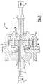
- FIG. 3is a sectional side view of an axle assembly of the present invention taken along line 3 — 3 in FIG. 2 ;
- FIG. 4is an expanded sectional view of a planetary gear assembly which receives input from both an electric motor and an engine;
- FIG. 5is a sectional side view of another axle assembly.
- FIG. 1illustrates a schematic, partial phantom view of a vehicle 10 . It should be understood that although a particular vehicle arrangement is disclosed in the illustrated embodiment, other vehicles will benefit from the present invention.
- An axle assembly 20is driven by an electric motor 24 .
- An engine 28such as an internal combustion engine, diesel engine, gas turbine or the like, may additionally be utilized to drive axle assembly 20 as a complement to the electric motor 24 .
- Shaft 16transmits drive from engine 28 to drive axle assembly 20 .
- Either or both the electric motor 24 and engine 28are utilized in selective combination in response to particular drive situations.
- the axle assembly 20defines an axis of rotation D substantially transverse to shaft 16 .
- the wheel hubs 22each support one or more wheels 26 , which are driven about the axis of rotation D.
- the axle assembly 20includes an axle housing 29 , which supports the wheel hubs 22 .
- the axle housing 29includes an electric motor housing portion 30 , which contains a gearbox 32 such as a gear reduction and a differential.
- the electric motor housing portion 30is preferably an enlarged semi-spherical portion centrally located in the axle housing 29 between the wheel hubs 22 .
- the electric motor 24is mounted to the electric motor housing portion 30 along an axis E, which is generally perpendicular to axis D.
- the electric motor 24is mounted directly to the electric motor housing portion 30 through fasteners 31 or the like.
- the electric motor housing portion 30is formed to specifically receive the electric motor 24 .
- the electric motor 24is mounted to the electric motor housing portion 30 opposite an input yoke 34 that is driven by the engine 28 through shaft 16 .
- the input yoke 34is preferably mounted along axis E to permit the engine 28 to alternatively or additionally drive the gearbox 32 in selective combination with the electric motor 24 .
- the gearbox 32drives the wheel hubs 22 through a first axle shaft 36 a and a second axle shaft 36 b , which rotates about axis D.
- the first axle shaft 36 a and second axle shaft 36 bare substantially enclosed within the axle housing 29 .
- the electric motor 24drives a motor shaft 38 through a coupling 40 .
- the coupling 40permits the electric motor 24 to be selectively attached to the motor shaft 38 to permit the electric motor 24 to be selectively engaged or disengaged therewith in response to a controller or the like. That is, the coupling 40 may be an active coupling such as a clutch or similar mechanism which responds to a controller. A worker in this art would recognize when to connect or disconnect coupling 40 to allow electric motor 24 to drive motor shaft 38 . Also, designing an appropriate control is within the level of skill in this art.
- the motor shaft 38is supported for rotation along axis E by a bearing 42 . It should be understood that various bearing and seal locations are included within the gearbox. One of ordinary skill in the art, with the benefit of this disclosure, would know various ways to mount motor shaft 38 .
- the motor shaft 38drives a pinion gear 44 that drives a ring gear 46 through an input gearbox 50 (also illustrated in FIG. 4 ).
- the input gearbox 50also receives power from the engine 28 through the input yoke 34 . That is, the input gearbox 50 operates as a transmission to receive drive input from both the engine 28 and the electric motor 24 .
- the motor shaft 38is preferably vertically offset from axis D (see FIG. 3 ).
- the ring gear 46drives the first axle shaft 36 a and the second axle shaft 36 b through the gearbox 32 such as a differential or the like (also illustrated in FIG. 2 ).
- the gearbox 32may additionally include a speed reduction gearbox to provide a relatively lightweight and compact axle assembly. It should be understood that one of ordinary skill, with the benefit of this disclosure, will understand the design of various gear trains which could be utilized to transfer power from the ring gear 46 to the axle shafts 36 a , 36 b.
- the input gearbox 50preferably includes a planetary gear assembly 51 .
- the electric motor shaft 38drives a sun gear 52 that drives a multiple of planet gears 54 that revolve within an outer gear 56 preferably formed within an input gearbox housing 58 .
- the planet gears 54drive a planet carrier 60 , which is mounted to the pinion gear 44 through splines 62 or the like.
- the planet carrier 60supports the planet gears 54 on pins 64 which define an axis of rotation for each of the planet gears 54 that is parallel to and displaced from axis E.
- the planetary gear assembly 51reduces the speed from the motor shaft 38 to the pinion gear 44 .
- the input yoke 34drives an input shaft 66 that is directly engaged with the planet carrier 60 through the pins 64 . That is, as the planet carrier 60 is mounted to the pinion gear 44 through the pins 64 , the input shaft 66 directly drives the pinion gear 44 without speed reduction.
- the input shaft 66is supported by a bearing 68 between the input shaft 66 and the input gearbox housing 58 .
- another axle assembly 20 ′may alternatively be powered by just the single electric motor 24 to provide a relatively lighter duty axle assembly 20 ′ for yet another vehicle configuration without major modification to the axle assembly 20 ′.
- the axle assembly 20 ′is driven by the electric motor 24 such that the input shaft 66 ′ does not require an input yoke.
- a cover 70protects an end of shaft 66 ′. It should be understood that various combinations of the axle assemblies described herein may be provided to particularly tailor an axle assembly to a particular vehicle in a modular manner.
- an electric motor 24 directly to the axle assembly 20utilizes relatively conventional axle, driveline, and suspension components to minimize redesign of the vehicle structure to provide a more efficient intercity transport and the like with hybrid power. That is, the electric motor 24 is mounted to the electric motor housing portion 30 to provide the advantages of utilizing an electric power system without significantly effecting how the axle assembly 20 is alternatively or additionally driven by conventional motive forces such as an internal combustion engine.
Landscapes
- Engineering & Computer Science (AREA)
- Mechanical Engineering (AREA)
- Chemical & Material Sciences (AREA)
- Combustion & Propulsion (AREA)
- Transportation (AREA)
- General Engineering & Computer Science (AREA)
- Hybrid Electric Vehicles (AREA)
- Arrangement Of Transmissions (AREA)
Abstract
Description
Claims (24)
Priority Applications (1)
| Application Number | Priority Date | Filing Date | Title |
|---|---|---|---|
| US10/860,505US7115057B2 (en) | 2004-06-03 | 2004-06-03 | Drive axle assembly for hybrid electric vehicle |
Applications Claiming Priority (1)
| Application Number | Priority Date | Filing Date | Title |
|---|---|---|---|
| US10/860,505US7115057B2 (en) | 2004-06-03 | 2004-06-03 | Drive axle assembly for hybrid electric vehicle |
Publications (2)
| Publication Number | Publication Date |
|---|---|
| US20050272547A1 US20050272547A1 (en) | 2005-12-08 |
| US7115057B2true US7115057B2 (en) | 2006-10-03 |
Family
ID=35449701
Family Applications (1)
| Application Number | Title | Priority Date | Filing Date |
|---|---|---|---|
| US10/860,505Expired - LifetimeUS7115057B2 (en) | 2004-06-03 | 2004-06-03 | Drive axle assembly for hybrid electric vehicle |
Country Status (1)
| Country | Link |
|---|---|
| US (1) | US7115057B2 (en) |
Cited By (22)
| Publication number | Priority date | Publication date | Assignee | Title |
|---|---|---|---|---|
| US20060065451A1 (en)* | 2004-09-28 | 2006-03-30 | Oshkosh Truck Corporation | Self-contained axle module |
| US20060070776A1 (en)* | 2004-09-28 | 2006-04-06 | Oshkosh Truck Corporation | Power takeoff for an electric vehicle |
| US20060172848A1 (en)* | 2005-02-03 | 2006-08-03 | Shine Far Metal Industry Co., Ltd. | Differential Mechanism |
| US20080237994A1 (en)* | 2007-03-27 | 2008-10-02 | Rolls-Royce Plc | Sealed joint |
| US20100071379A1 (en)* | 2008-09-25 | 2010-03-25 | Honeywell International Inc. | Effusion cooling techniques for combustors in engine assemblies |
| US20100116569A1 (en)* | 2004-09-28 | 2010-05-13 | Oshkosh Corporation | Self-contained axle module |
| US20110000721A1 (en)* | 2009-07-02 | 2011-01-06 | Thermal Motor Innovations, Llc | Hybrid parallel load assist systems and methods |
| US20110011206A1 (en)* | 2009-07-14 | 2011-01-20 | Knight Donn C | Driveline yoke with brake rotor |
| US20110094807A1 (en)* | 2009-10-26 | 2011-04-28 | Steve Pruitt | Electric drive system for passive vehicle |
| US20110105917A1 (en)* | 2009-10-29 | 2011-05-05 | Cnsystems Medizintechnik Ag | Digital Control Method for Measuring Blood Pressure |
| DE102010034130A1 (en)* | 2010-08-12 | 2012-02-16 | Volkswagen Ag | Drive train for use in small motor vehicles, has gearbox standing in engagement with differential gear and comprising planetary gear stage driveable by input shaft and providing fixed gear transmission ratio between rotor and gear |
| US20120165147A1 (en)* | 2009-06-23 | 2012-06-28 | Fisker Automotive, Inc. | Drive configurations for high speed motor drive systems |
| US8545353B2 (en) | 2009-06-24 | 2013-10-01 | Fisker Automotive, Inc. | Drive configurations for high hybrid series/parallel high speed motor drive systems |
| US8798828B2 (en) | 2007-12-19 | 2014-08-05 | Lester J. Erlston | Kinetic energy recovery and electric drive for vehicles |
| US8858379B2 (en) | 2012-09-21 | 2014-10-14 | Arvinmeritor Technology, Llc | Axle assembly having an electric motor module |
| US9969252B2 (en)* | 2013-05-30 | 2018-05-15 | BAE Systems Hägglunds Aktriebolag | Electric drive device for driving a motor vehicle |
| US10208846B2 (en)* | 2017-03-10 | 2019-02-19 | Arvinmeritor Technology, Llc | Axle assembly having a drive pinion support bearing and a method of assembly |
| WO2019051314A1 (en) | 2017-09-08 | 2019-03-14 | Chu Shaun | Differential system including stepped planetary gears with differential rate governed by variable speed motor and associated method of operation |
| US10907715B2 (en) | 2016-04-20 | 2021-02-02 | Shaun Chu | Differential system with differential rate governed by variable speed motor and associated method of operation |
| US11667180B2 (en) | 2020-11-24 | 2023-06-06 | Dana Heavy Vehicle Systems Group, Llc | Cover for an electric axle assembly |
| US11981192B2 (en) | 2020-10-30 | 2024-05-14 | Dana (Wuxi) Technology Co., Ltd | Electric driveline and electric vehicle using the electric driveline |
| US20250153563A1 (en)* | 2023-11-15 | 2025-05-15 | Arvinmeritor Technology, Llc | Axle assembly devices, systems, and methods |
Families Citing this family (8)
| Publication number | Priority date | Publication date | Assignee | Title |
|---|---|---|---|---|
| SE534474C2 (en) | 2010-01-14 | 2011-09-06 | Bae Systems Haegglunds Ab | Drive line with pendulum suspension drive shaft |
| CN102019846A (en)* | 2010-12-08 | 2011-04-20 | 东华大学 | Power transmission simplification method for hybrid electric vehicle |
| WO2017114419A1 (en)* | 2015-12-31 | 2017-07-06 | 比亚迪股份有限公司 | Vehicle and drive axle component for use in vehicle |
| JP6858838B2 (en)* | 2016-03-23 | 2021-04-14 | チュー,ショーン | Regenerative differential for differential steering and front wheel steering vehicles |
| US10697528B2 (en) | 2016-03-23 | 2020-06-30 | Shaun Chu | Regenerative differential for differentially steered and front-wheel steered vehicles |
| US10677332B2 (en) | 2017-09-19 | 2020-06-09 | Schaffler Technologies AG & Co. KG | Hybrid module including electric motor on front differential |
| EP3734120A1 (en)* | 2019-05-02 | 2020-11-04 | Flender GmbH | Transmission with reduced power loss, operating method and industry application |
| CN110154648B (en)* | 2019-06-28 | 2024-10-18 | 徐工集团工程机械股份有限公司科技分公司 | Vehicle drive axle and vehicle |
Citations (17)
| Publication number | Priority date | Publication date | Assignee | Title |
|---|---|---|---|---|
| US3315544A (en)* | 1964-12-07 | 1967-04-25 | Axel Wickman Transmissions Ltd | Vehicular driving axle |
| US4050328A (en)* | 1972-10-05 | 1977-09-27 | Eaton Corporation | Four-wheel drive vehicle with drive transfer gear assembly |
| US5168946A (en)* | 1991-09-09 | 1992-12-08 | General Electric Company | Track-laying vehicle electric drive system |
| US5713425A (en)* | 1996-01-16 | 1998-02-03 | Ford Global Technologies, Inc. | Parallel hybrid powertrain for an automotive vehicle |
| US5878830A (en)* | 1997-02-18 | 1999-03-09 | Meritor Heavy Vehicle Systems, Llc. | Space saving mounting for electrically driven vehicle wheels |
| US5924504A (en) | 1997-02-18 | 1999-07-20 | Meritor Heavy Vehicle Systems, Llc | Suspension drive unit assembly for an electrically driven vehicle |
| US6024182A (en)* | 1995-09-11 | 2000-02-15 | Honda Giken Kogyo Kabushiki Kaisha | Coupling device between left and right wheels of vehicle |
| DE20010563U1 (en)* | 2000-06-14 | 2000-10-05 | Ewald Speth Antriebstechnik Gm | Directly driven drive axle with planetary differential gear stage |
| US6276474B1 (en) | 1997-02-18 | 2001-08-21 | Rockwell Heavy Vehicle Systems, Inc. | Low floor drive unit assembly for an electrically driven vehicle |
| US6431298B1 (en) | 1999-04-13 | 2002-08-13 | Meritor Heavy Vehicle Systems, Llc | Drive unit assembly for an electrically driven vehicle |
| US20030054910A1 (en)* | 2001-09-20 | 2003-03-20 | Hans-Peter Nett | Drive unit |
| US6540035B2 (en)* | 1996-05-02 | 2003-04-01 | Toyota Jidosha Kabushiki Kaisha | Hybrid vehicle |
| US6661109B2 (en)* | 2000-03-01 | 2003-12-09 | Hitachi, Ltd. | Electric generating system for automobiles and its control method |
| US20040192487A1 (en)* | 2003-03-31 | 2004-09-30 | Tochigi Fuji Sangyo Kabushiki Kaisha | Torque transmission coupling |
| US20040220011A1 (en)* | 2003-05-02 | 2004-11-04 | Gerhard Gumpoltsberger | Transmission for distributing a drive torque |
| US6935451B2 (en)* | 2002-10-29 | 2005-08-30 | Arvinmeritor Technology, Llc | Axle assembly with parallel drive system for electric hybrid vehicles |
| US6991571B2 (en)* | 2003-12-09 | 2006-01-31 | Arvinmeritor Technology, Llc | Variable ratio drive system |
- 2004
- 2004-06-03USUS10/860,505patent/US7115057B2/ennot_activeExpired - Lifetime
Patent Citations (17)
| Publication number | Priority date | Publication date | Assignee | Title |
|---|---|---|---|---|
| US3315544A (en)* | 1964-12-07 | 1967-04-25 | Axel Wickman Transmissions Ltd | Vehicular driving axle |
| US4050328A (en)* | 1972-10-05 | 1977-09-27 | Eaton Corporation | Four-wheel drive vehicle with drive transfer gear assembly |
| US5168946A (en)* | 1991-09-09 | 1992-12-08 | General Electric Company | Track-laying vehicle electric drive system |
| US6024182A (en)* | 1995-09-11 | 2000-02-15 | Honda Giken Kogyo Kabushiki Kaisha | Coupling device between left and right wheels of vehicle |
| US5713425A (en)* | 1996-01-16 | 1998-02-03 | Ford Global Technologies, Inc. | Parallel hybrid powertrain for an automotive vehicle |
| US6540035B2 (en)* | 1996-05-02 | 2003-04-01 | Toyota Jidosha Kabushiki Kaisha | Hybrid vehicle |
| US6276474B1 (en) | 1997-02-18 | 2001-08-21 | Rockwell Heavy Vehicle Systems, Inc. | Low floor drive unit assembly for an electrically driven vehicle |
| US5924504A (en) | 1997-02-18 | 1999-07-20 | Meritor Heavy Vehicle Systems, Llc | Suspension drive unit assembly for an electrically driven vehicle |
| US5878830A (en)* | 1997-02-18 | 1999-03-09 | Meritor Heavy Vehicle Systems, Llc. | Space saving mounting for electrically driven vehicle wheels |
| US6431298B1 (en) | 1999-04-13 | 2002-08-13 | Meritor Heavy Vehicle Systems, Llc | Drive unit assembly for an electrically driven vehicle |
| US6661109B2 (en)* | 2000-03-01 | 2003-12-09 | Hitachi, Ltd. | Electric generating system for automobiles and its control method |
| DE20010563U1 (en)* | 2000-06-14 | 2000-10-05 | Ewald Speth Antriebstechnik Gm | Directly driven drive axle with planetary differential gear stage |
| US20030054910A1 (en)* | 2001-09-20 | 2003-03-20 | Hans-Peter Nett | Drive unit |
| US6935451B2 (en)* | 2002-10-29 | 2005-08-30 | Arvinmeritor Technology, Llc | Axle assembly with parallel drive system for electric hybrid vehicles |
| US20040192487A1 (en)* | 2003-03-31 | 2004-09-30 | Tochigi Fuji Sangyo Kabushiki Kaisha | Torque transmission coupling |
| US20040220011A1 (en)* | 2003-05-02 | 2004-11-04 | Gerhard Gumpoltsberger | Transmission for distributing a drive torque |
| US6991571B2 (en)* | 2003-12-09 | 2006-01-31 | Arvinmeritor Technology, Llc | Variable ratio drive system |
Cited By (33)
| Publication number | Priority date | Publication date | Assignee | Title |
|---|---|---|---|---|
| US20100116569A1 (en)* | 2004-09-28 | 2010-05-13 | Oshkosh Corporation | Self-contained axle module |
| US20060070776A1 (en)* | 2004-09-28 | 2006-04-06 | Oshkosh Truck Corporation | Power takeoff for an electric vehicle |
| US8561735B2 (en) | 2004-09-28 | 2013-10-22 | Oshkosh Corporation | Self-contained axle module |
| US20060065451A1 (en)* | 2004-09-28 | 2006-03-30 | Oshkosh Truck Corporation | Self-contained axle module |
| US7357203B2 (en) | 2004-09-28 | 2008-04-15 | Oshkosh Truck Corporation | Self-contained axle module |
| US20080150350A1 (en)* | 2004-09-28 | 2008-06-26 | Oshkosh Corporation | Self-contained axle module |
| US7931103B2 (en) | 2004-09-28 | 2011-04-26 | Oshkosh Corporation | Electric vehicle with power takeoff |
| US7448460B2 (en)* | 2004-09-28 | 2008-11-11 | Oshkosh Corporation | Power takeoff for an electric vehicle |
| US7223193B2 (en)* | 2005-02-03 | 2007-05-29 | Shine Far Metal Industry Co., Ltd. | Differential mechanism |
| US20060172848A1 (en)* | 2005-02-03 | 2006-08-03 | Shine Far Metal Industry Co., Ltd. | Differential Mechanism |
| US20080237994A1 (en)* | 2007-03-27 | 2008-10-02 | Rolls-Royce Plc | Sealed joint |
| US9702443B2 (en) | 2007-12-19 | 2017-07-11 | Kerstech, Inc. | Kinetic energy recovery and hydraulic drive for vehicles |
| US8798828B2 (en) | 2007-12-19 | 2014-08-05 | Lester J. Erlston | Kinetic energy recovery and electric drive for vehicles |
| US20100071379A1 (en)* | 2008-09-25 | 2010-03-25 | Honeywell International Inc. | Effusion cooling techniques for combustors in engine assemblies |
| US20120165147A1 (en)* | 2009-06-23 | 2012-06-28 | Fisker Automotive, Inc. | Drive configurations for high speed motor drive systems |
| US8491432B2 (en)* | 2009-06-23 | 2013-07-23 | Fisker Automotive, Inc. | Drive configurations for high speed motor drive systems |
| US8545353B2 (en) | 2009-06-24 | 2013-10-01 | Fisker Automotive, Inc. | Drive configurations for high hybrid series/parallel high speed motor drive systems |
| US20110000721A1 (en)* | 2009-07-02 | 2011-01-06 | Thermal Motor Innovations, Llc | Hybrid parallel load assist systems and methods |
| US20110011206A1 (en)* | 2009-07-14 | 2011-01-20 | Knight Donn C | Driveline yoke with brake rotor |
| US20110094807A1 (en)* | 2009-10-26 | 2011-04-28 | Steve Pruitt | Electric drive system for passive vehicle |
| US20110105917A1 (en)* | 2009-10-29 | 2011-05-05 | Cnsystems Medizintechnik Ag | Digital Control Method for Measuring Blood Pressure |
| DE102010034130B4 (en)* | 2010-08-12 | 2020-11-12 | Volkswagen Ag | Drive train of a motor vehicle |
| DE102010034130A1 (en)* | 2010-08-12 | 2012-02-16 | Volkswagen Ag | Drive train for use in small motor vehicles, has gearbox standing in engagement with differential gear and comprising planetary gear stage driveable by input shaft and providing fixed gear transmission ratio between rotor and gear |
| US8858379B2 (en) | 2012-09-21 | 2014-10-14 | Arvinmeritor Technology, Llc | Axle assembly having an electric motor module |
| US9969252B2 (en)* | 2013-05-30 | 2018-05-15 | BAE Systems Hägglunds Aktriebolag | Electric drive device for driving a motor vehicle |
| US10907715B2 (en) | 2016-04-20 | 2021-02-02 | Shaun Chu | Differential system with differential rate governed by variable speed motor and associated method of operation |
| US10208846B2 (en)* | 2017-03-10 | 2019-02-19 | Arvinmeritor Technology, Llc | Axle assembly having a drive pinion support bearing and a method of assembly |
| WO2019051314A1 (en) | 2017-09-08 | 2019-03-14 | Chu Shaun | Differential system including stepped planetary gears with differential rate governed by variable speed motor and associated method of operation |
| EP3679276A4 (en)* | 2017-09-08 | 2021-03-24 | Chu, Shaun | Differential system including stepped planetary gears with differential rate governed by variable speed motor and associated method of operation |
| US11111996B2 (en) | 2017-09-08 | 2021-09-07 | Shaun Chu | Differential system including stepped planetary gears with differential rate governed by variable speed motor and associated method of operation |
| US11981192B2 (en) | 2020-10-30 | 2024-05-14 | Dana (Wuxi) Technology Co., Ltd | Electric driveline and electric vehicle using the electric driveline |
| US11667180B2 (en) | 2020-11-24 | 2023-06-06 | Dana Heavy Vehicle Systems Group, Llc | Cover for an electric axle assembly |
| US20250153563A1 (en)* | 2023-11-15 | 2025-05-15 | Arvinmeritor Technology, Llc | Axle assembly devices, systems, and methods |
Also Published As
| Publication number | Publication date |
|---|---|
| US20050272547A1 (en) | 2005-12-08 |
Similar Documents
| Publication | Publication Date | Title |
|---|---|---|
| US7115057B2 (en) | Drive axle assembly for hybrid electric vehicle | |
| JP5137596B2 (en) | Hybrid electric vehicle powertrain | |
| US7316627B2 (en) | Integrated two-speed motor | |
| US6978853B2 (en) | Axle assembly with parallel mounted electric motors | |
| US6719654B2 (en) | Power train of a motor vehicle | |
| USRE36678E (en) | Hybrid vehicle | |
| JP3656841B2 (en) | Drive unit with electric motor | |
| US7694761B2 (en) | Hybrid drive chain and hybrid vehicle equipped with same | |
| JP7496875B2 (en) | Gearbox for electric powertrain | |
| US20050124450A1 (en) | Variable ratio drive system | |
| US20110124455A1 (en) | Hybrid drive train of a motor vehicle | |
| US20070243965A1 (en) | Electro-mechanical transmission | |
| CN101646580A (en) | Hybrid drive, particularly for a motor vehicle | |
| KR20060052262A (en) | Power-assisted differential assembly | |
| JP2005147404A (en) | Hybrid power transmission mechanism | |
| JP2002154343A (en) | Power transmission mechanism for front and rear wheel drive vehicles | |
| US10677332B2 (en) | Hybrid module including electric motor on front differential | |
| US20200317042A1 (en) | Motor integration assembly | |
| US12179571B2 (en) | Electric powertrain for a vehicle | |
| EP3825161B1 (en) | Drivetrain system having an axle assembly | |
| CN115303041B (en) | Axle assembly having a gear reduction module with multiple gear sets | |
| EP3750728B1 (en) | Vehicle powertrain system | |
| CN115704462A (en) | Transmission for a vehicle and drive train having such a transmission | |
| CN115593213A (en) | Electric power assembly for vehicle | |
| US6569048B1 (en) | Tandem torque converter |
Legal Events
| Date | Code | Title | Description |
|---|---|---|---|
| AS | Assignment | Owner name:ARVINMERITOR TECHNOLOGY, LLC, MICHIGAN Free format text:ASSIGNMENT OF ASSIGNORS INTEREST;ASSIGNOR:HOUSE, DEAN M.;REEL/FRAME:015436/0020 Effective date:20040601 | |
| STCF | Information on status: patent grant | Free format text:PATENTED CASE | |
| FPAY | Fee payment | Year of fee payment:4 | |
| AS | Assignment | Owner name:JPMORGAN CHASE BANK, N.A., AS ADMINISTRATIVE AGENT Free format text:SECURITY AGREEMENT;ASSIGNOR:ARVINMERITOR TECHNOLOGY, LLC;REEL/FRAME:028106/0360 Effective date:20120423 | |
| FPAY | Fee payment | Year of fee payment:8 | |
| MAFP | Maintenance fee payment | Free format text:PAYMENT OF MAINTENANCE FEE, 12TH YEAR, LARGE ENTITY (ORIGINAL EVENT CODE: M1553) Year of fee payment:12 | |
| AS | Assignment | Owner name:AXLETECH INTERNATIONAL IP HOLDINGS, LLC, MICHIGAN Free format text:RELEASE BY SECURED PARTY;ASSIGNOR:JPMORGAN CHASE BANK, N.A., AS ADMINISTRATIVE AGENT;REEL/FRAME:061521/0550 Effective date:20220803 Owner name:MERITOR TECHNOLOGY, LLC, MICHIGAN Free format text:RELEASE BY SECURED PARTY;ASSIGNOR:JPMORGAN CHASE BANK, N.A., AS ADMINISTRATIVE AGENT;REEL/FRAME:061521/0550 Effective date:20220803 Owner name:MOTOR HEAVY VEHICLE SYSTEMS, LLC, MICHIGAN Free format text:RELEASE BY SECURED PARTY;ASSIGNOR:JPMORGAN CHASE BANK, N.A., AS ADMINISTRATIVE AGENT;REEL/FRAME:061521/0550 Effective date:20220803 Owner name:ARVINMERITOR OE, LLC, MICHIGAN Free format text:RELEASE BY SECURED PARTY;ASSIGNOR:JPMORGAN CHASE BANK, N.A., AS ADMINISTRATIVE AGENT;REEL/FRAME:061521/0550 Effective date:20220803 Owner name:MERITOR HEAVY VEHICLE SYSTEMS, LLC, MICHIGAN Free format text:RELEASE BY SECURED PARTY;ASSIGNOR:JPMORGAN CHASE BANK, N.A., AS ADMINISTRATIVE AGENT;REEL/FRAME:061521/0550 Effective date:20220803 Owner name:ARVINMERITOR TECHNOLOGY, LLC, MICHIGAN Free format text:RELEASE BY SECURED PARTY;ASSIGNOR:JPMORGAN CHASE BANK, N.A., AS ADMINISTRATIVE AGENT;REEL/FRAME:061521/0550 Effective date:20220803 Owner name:MAREMOUNT CORPORATION, MICHIGAN Free format text:RELEASE BY SECURED PARTY;ASSIGNOR:JPMORGAN CHASE BANK, N.A., AS ADMINISTRATIVE AGENT;REEL/FRAME:061521/0550 Effective date:20220803 Owner name:EUCLID INDUSTRIES, LLC, MICHIGAN Free format text:RELEASE BY SECURED PARTY;ASSIGNOR:JPMORGAN CHASE BANK, N.A., AS ADMINISTRATIVE AGENT;REEL/FRAME:061521/0550 Effective date:20220803 Owner name:GABRIEL RIDE CONTROL PRODUCTS, INC., MICHIGAN Free format text:RELEASE BY SECURED PARTY;ASSIGNOR:JPMORGAN CHASE BANK, N.A., AS ADMINISTRATIVE AGENT;REEL/FRAME:061521/0550 Effective date:20220803 Owner name:ARVIN TECHNOLOGIES, INC., MICHIGAN Free format text:RELEASE BY SECURED PARTY;ASSIGNOR:JPMORGAN CHASE BANK, N.A., AS ADMINISTRATIVE AGENT;REEL/FRAME:061521/0550 Effective date:20220803 Owner name:MERITOR TRANSMISSION CORPORATION, MICHIGAN Free format text:RELEASE BY SECURED PARTY;ASSIGNOR:JPMORGAN CHASE BANK, N.A., AS ADMINISTRATIVE AGENT;REEL/FRAME:061521/0550 Effective date:20220803 Owner name:ARVINMERITOR, INC., MICHIGAN Free format text:RELEASE BY SECURED PARTY;ASSIGNOR:JPMORGAN CHASE BANK, N.A., AS ADMINISTRATIVE AGENT;REEL/FRAME:061521/0550 Effective date:20220803 |