US7114963B2 - Modular high speed connector assembly - Google Patents
Modular high speed connector assemblyDownload PDFInfo
- Publication number
- US7114963B2 US7114963B2US11/043,846US4384605AUS7114963B2US 7114963 B2US7114963 B2US 7114963B2US 4384605 AUS4384605 AUS 4384605AUS 7114963 B2US7114963 B2US 7114963B2
- Authority
- US
- United States
- Prior art keywords
- contact
- connector
- contact retention
- contacts
- sections
- Prior art date
- Legal status (The legal status is an assumption and is not a legal conclusion. Google has not performed a legal analysis and makes no representation as to the accuracy of the status listed.)
- Expired - Lifetime
Links
- 230000014759maintenance of locationEffects0.000claimsabstractdescription83
- 230000013011matingEffects0.000claimsabstractdescription21
- 230000007704transitionEffects0.000claimsdescription10
- 230000005540biological transmissionEffects0.000description4
- 210000005069earsAnatomy0.000description4
- 239000004020conductorSubstances0.000description2
- 239000000463materialSubstances0.000description2
- 238000000034methodMethods0.000description2
- 230000002250progressing effectEffects0.000description2
- 230000001154acute effectEffects0.000description1
- 238000005452bendingMethods0.000description1
- 230000007423decreaseEffects0.000description1
- 230000001747exhibiting effectEffects0.000description1
- 239000012212insulatorSubstances0.000description1
- 238000004519manufacturing processMethods0.000description1
- 230000004048modificationEffects0.000description1
- 238000012986modificationMethods0.000description1
- 238000000465mouldingMethods0.000description1
- 230000000717retained effectEffects0.000description1
Images


Classifications
- H—ELECTRICITY
- H01—ELECTRIC ELEMENTS
- H01R—ELECTRICALLY-CONDUCTIVE CONNECTIONS; STRUCTURAL ASSOCIATIONS OF A PLURALITY OF MUTUALLY-INSULATED ELECTRICAL CONNECTING ELEMENTS; COUPLING DEVICES; CURRENT COLLECTORS
- H01R13/00—Details of coupling devices of the kinds covered by groups H01R12/70 or H01R24/00 - H01R33/00
- H01R13/648—Protective earth or shield arrangements on coupling devices, e.g. anti-static shielding
- H01R13/658—High frequency shielding arrangements, e.g. against EMI [Electro-Magnetic Interference] or EMP [Electro-Magnetic Pulse]
- H01R13/6591—Specific features or arrangements of connection of shield to conductive members
- H01R13/6594—Specific features or arrangements of connection of shield to conductive members the shield being mounted on a PCB and connected to conductive members
- H01R13/6595—Specific features or arrangements of connection of shield to conductive members the shield being mounted on a PCB and connected to conductive members with separate members fixing the shield to the PCB
- H—ELECTRICITY
- H01—ELECTRIC ELEMENTS
- H01R—ELECTRICALLY-CONDUCTIVE CONNECTIONS; STRUCTURAL ASSOCIATIONS OF A PLURALITY OF MUTUALLY-INSULATED ELECTRICAL CONNECTING ELEMENTS; COUPLING DEVICES; CURRENT COLLECTORS
- H01R12/00—Structural associations of a plurality of mutually-insulated electrical connecting elements, specially adapted for printed circuits, e.g. printed circuit boards [PCB], flat or ribbon cables, or like generally planar structures, e.g. terminal strips, terminal blocks; Coupling devices specially adapted for printed circuits, flat or ribbon cables, or like generally planar structures; Terminals specially adapted for contact with, or insertion into, printed circuits, flat or ribbon cables, or like generally planar structures
- H—ELECTRICITY
- H01—ELECTRIC ELEMENTS
- H01R—ELECTRICALLY-CONDUCTIVE CONNECTIONS; STRUCTURAL ASSOCIATIONS OF A PLURALITY OF MUTUALLY-INSULATED ELECTRICAL CONNECTING ELEMENTS; COUPLING DEVICES; CURRENT COLLECTORS
- H01R13/00—Details of coupling devices of the kinds covered by groups H01R12/70 or H01R24/00 - H01R33/00
- H01R13/40—Securing contact members in or to a base or case; Insulating of contact members
- H01R13/405—Securing in non-demountable manner, e.g. moulding, riveting
- H—ELECTRICITY
- H01—ELECTRIC ELEMENTS
- H01R—ELECTRICALLY-CONDUCTIVE CONNECTIONS; STRUCTURAL ASSOCIATIONS OF A PLURALITY OF MUTUALLY-INSULATED ELECTRICAL CONNECTING ELEMENTS; COUPLING DEVICES; CURRENT COLLECTORS
- H01R13/00—Details of coupling devices of the kinds covered by groups H01R12/70 or H01R24/00 - H01R33/00
- H01R13/46—Bases; Cases
- H01R13/502—Bases; Cases composed of different pieces
- H—ELECTRICITY
- H01—ELECTRIC ELEMENTS
- H01R—ELECTRICALLY-CONDUCTIVE CONNECTIONS; STRUCTURAL ASSOCIATIONS OF A PLURALITY OF MUTUALLY-INSULATED ELECTRICAL CONNECTING ELEMENTS; COUPLING DEVICES; CURRENT COLLECTORS
- H01R43/00—Apparatus or processes specially adapted for manufacturing, assembling, maintaining, or repairing of line connectors or current collectors or for joining electric conductors
- H01R43/20—Apparatus or processes specially adapted for manufacturing, assembling, maintaining, or repairing of line connectors or current collectors or for joining electric conductors for assembling or disassembling contact members with insulating base, case or sleeve
- H01R43/24—Assembling by moulding on contact members
Definitions
- the present inventiongenerally relates to an electrical connector assembly, and more particularly to a high speed modular connector configuration.
- SCAsingle connector attachment
- SCA-2SCA series 1
- SCA-2SCA series 2
- the SCA-2 connectorsare available in 20, 40 and 80 pin position configurations and contain through-hole contacts or compliant pin contacts arranged on a predetermined centerline spacing.
- the SCA-2 connector plugsare available in vertical and straddle mount, while the SCA-2 connector receptacles are available in right-angle, vertical, press-fit vertical, extended height press-fit vertical and extended height vertical arrangements. These SCA-2 connectors are compatible with SCA-1 board-to-board connectors.
- conventional SCA connectorshave met with certain limitations. As data transmission speeds increase, the conventional SCA connectors are unable to maintain a desired signal-to-noise ratio (SNR) and experience undue increases in interference such as in crosstalk.
- SNRsignal-to-noise ratio
- Conventional SCA-2 connectorsretain the contacts within an insulated housing of the connector utilizing a “stitched design”.
- the insulated housingis formed first with an arrangement of passages through the housing. Contacts are then inserted through the passages into the housing.
- the stitched designcreates an uneven surface environment surrounding each contact as the housing touches the contact at certain points and does not touch the contact at other points, thereby exposing regions of the contact surface to air.
- the uneven surface environmentundesirably impacts the impedance characteristics of the contact, particularly at high data rates.
- conventional SCA-2 connectorsutilize contacts that include multiple curves and bends along the length of the contact.
- the curves and bendsundesirably impact the signal characteristics of the contact, particularly at high data rates.
- the connectorincludes a contact, an outer shell and a contact retention module.
- the contacthas a straight body portion defining, and extending along, a linear axis.
- the body portionhas one end formed integral with a contact tail that is configured to be joined to a circuit board.
- the body portionhas an opposed end formed integral with a curved engagement portion configured to engage a mating connector.
- the outer shellhas a mating end configured to be joined with a mating connector and has a board-engaging end configured to be joined to a circuit board.
- the outer shellhas an interior cavity opening onto the mating end and an open socket facing the board-engaging end.
- the contact retention moduleis over molded at least about the straight body portion of the contact. The contact retention module is held within the open socket of the outer shell with the curved engagement portion extending beyond the contact retention module into the cavity.
- the contact retention modulemay be over molded about multiple contacts arranged in a row along a length of the contact retention module.
- a pair of contact retention modulesmay be arranged parallel to, and abutted against, one another within the socket of the outer shell.
- the pair of contact retention modulesretain corresponding contacts in an arrangement opposite to, and facing, one another in the cavity.
- the curved engagement portions of the contacts in each contact pairare offset from one another in a make-first-break-last arrangement.
- the body portions of opposed contacts within each pair of contactsmay extend toward one another, within the corresponding contact retention modules, in a V-shaped manner.
- each contactmay have first and second sections with different widths, wherein the first section is over molded or otherwise evenly and uniformly embedded within the contact retention module while the second section projects from the contact retention module, and is evenly and uniformly surrounded by air in the cavity of the outer shell.
- the width of the second sectionmay be greater than the width of the first section to maintain consistent impedance characteristics for signals traveling through the body portion.
- the body portionmay have a transition area with a tapered width proximate a face of the contact retention module between wherein the taper expands between the first and second sections as the body portion progresses from the contact retention module into the interior cavity of the outer shell.
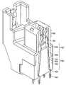
- FIG. 1illustrates a perspective view of a receptacle connector formed in accordance with an embodiment of the present invention.
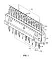
- FIG. 2illustrates a perspective view of a first side of a contact retention module retaining a plurality of contacts in accordance with an embodiment of the present invention.
- FIG. 3illustrates a perspective view of an opposite side of the contact retention module and contacts of FIG. 2 .
- FIG. 4illustrates a side sectional view taken along line 4 — 4 in FIG. 1 of the receptacle connector of FIG. 1 .
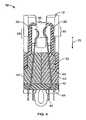
- FIG. 5illustrates a perspective view of a portion of a group of contacts held together during assembly in accordance with an embodiment of the present invention.
- FIG. 6illustrates a perspective view of a receptacle connector formed in accordance with an alternative embodiment of the present invention.
- FIG. 7illustrates a perspective view of a portion of the receptacle connector of FIG. 6 when cut along line 7 — 7 in FIG. 6 .
- FIG. 1illustrates a receptacle connector 10 formed in accordance with an embodiment of the present invention.
- the receptacle connector 10includes an outer shell 12 having a main body 14 with base posts 16 extending downward from the main body 14 toward a board-engaging end 18 of the outer shell 12 .
- the base posts 16are configured to rest upon a circuit board and are spaced apart from one another to define an open socket 20 there between.
- the open socket 20extends between the base posts 16 along a socket border edge 21 and has an open face at the board-engaging end 18 .
- the open socket 20receives a pair of contact retention modules 40 (only one of which is shown in FIG. 1 ).
- the contact retention modules 40are also referred to as “chicklets”.
- Each contact retention module 40is formed about a row of contacts 32 .
- An organizer 42is provided below the contact retention module 40 and is fit over contact tails 44 on each contact 32 .
- the organizer 42aligns the contact tails 44 in a desired spacing and alignment and prevents the contact tails 44 from bending when inserted into the vias within a circuit board on which the receptacle connector 10 is mounted.
- the contact tails 44may be formed as eye-of-needle pins, compliant pins, surface mount pads and the like.
- the outer shell 12includes alignment ears 22 extending upward from the main body 14 in a direction opposite to the base posts 16 .
- the alignment ears 22are located proximate opposite sides of the receptacle connector 10 .
- the alignment ears 22guide alignment with a mating plug type connector (not shown).
- Each alignment ear 22has an open U-shaped cross-section that faces inward.
- a grounding pin 36is held within the interior of each alignment ear 22 .
- the grounding pins 36are formed integral with board locks 38 that project along and downward beyond the base posts 16 .
- the board locks 38are securely received, in a fiction fit, within grounded openings in the circuit board.
- the grounding pins 36engage corresponding grounding contacts on the mating connector to provide a grounding interface between the mating connector and the circuit board, to which the receptacle connector 10 is joined.
- a D-shaped interface 24extends upward from a ledge 26 formed on the main body 14 .
- the D-shaped interface 24extends toward a mating end 28 of the receptacle connector 10 .
- the D-shaped interface 24includes an opening 30 to an interior cavity 34 , in which a plurality of contacts 32 are held.
- the main body 14includes windows 46 that are configured to accept and snappable engage retention detents 48 formed on the sides of the contact retention module 42 to retain the contact retention module 40 within the socket 20 of the outer shell 12 .
- FIG. 2illustrates a perspective view of a contact retention module 40 with a row of contacts 32 embedded therein.
- the contact retention module 40may be over molded or otherwise formed over the row of contacts 32 , while the contacts 32 are held in a particular alignment and spacing with respect to one another by linking tabs 50 .
- the tabs 50are removed after the contacts 32 are securely embedded within the contact retention module 40 .
- the contact retention module 40includes an outer side 52 having the retention detents 48 molded thereon.
- Upper and lower ledges 54 and 56extend along the top and bottom, respectively, of the outer side 52 .
- the upper and lower ledges 54 and 56are configured to fit against corresponding mating features in the interior of the outer shell 12 such as the socket border edge 21 ( FIG. 1 ) of the open socket 20 and the interior of the ledge 26 , respectively.
- FIG. 3illustrates the interior side 58 of the contact retention module 40 .
- the interior side 58includes a vertical rib 60 that is configured to abut against a corresponding rib 60 or similar feature on an adjoining contact retention module 40 to assist in ensuring that the pair of contact retention modules 40 are properly aligned with one another along the length of the contact retention module 40 in the directions denoted by arrow 62 .
- FIG. 4illustrates a cross-sectional view of the receptacle connector 10 taken along line 4 — 4 in FIG. 1 .
- the outer shell 12receives a pair of contact retention modules 40 in a side-by-side abutting manner.
- the organizer 42fits over the contact tails 44 of the contacts 32 and abuts against the bottom of both contact retention modules 40 .
- the D-shaped interface 24surrounds the interior cavity 32 which communicates with the opening 30 through which contacts of a mating connector are inserted.
- Each contact 32includes a straight main body 64 that extends along a linear axis and has one end formed integral with the contact tail 44 at an alignment bend 66 .
- the alignment bends 66position the contact tails 44 at a desired spacing and in a staggered footprint to align with vias in the circuit board, to which the receptacle connector 10 is joined.
- An end of the main body 64opposite to the contact tails 44 , is formed integral with a curved engagement portion 68 .
- a pair of contacts 32are arranged opposite to one another and in a facing manner with the curved engagement ends 68 within a pair of contacts 32 being offset with respect to one another in the direction of arrow 70 to form a make-first-break-last contact combination.
- the main bodies 64 of the contacts 32 in a pair of contacts 32are held within corresponding contact retention modules 40 in an angled manner and oriented toward one another to form a V-shape with the curved engagement portions 68 spaced closer to one another than the contact tails 44 .
- the portion of the main body 64 embedded within the contact retention module 40is entirely straight without any bends or curves.
- the contact retention module 40of an insulated material about the contacts 32 , such as an over molding process and the like.
- the contacts 32are embedded and sealed within the contact retention module 40 to form an air-less environment along and around the entire surface of the section of each contact 32 embedded in the contact retention module 40 .
- the entire surface of the section of the contact 34 that is embedded within the contact retention module 40engages, evenly and uniformly, the insulated material from which the contact retention module 40 is formed.
- the contact retention module 40maintains the main bodies 64 of the row of contacts 32 within a common plane denoted by dashed lines 72 extending along the length of the contact retention module 40 , such that the curved engagement portions 68 are evenly aligned with one another when extending from a top 75 of the contact retention module 40 .
- the contact retention module 40further maintains the contact tails 44 in a staggered footprint such that every other contact tail 44 is offset from one another along the length of the contact retention module 40 .
- the contact tails 44are staggered within first and second planes denoted by reference numerals 74 and 76 that are separated by a gap 78 .
- the contact tails 44project perpendicularly from the board facing end 80 of the contact retention module 40 , while the main body 64 and curved engagement portion 68 of each contact 32 extend at an acute angle from a plane of the top 75 of the contact retention module 40 .
- FIG. 5illustrates an isometric view of a portion of a group of contacts 32 joined with one another by linking tabs 50 .
- FIG. 5better illustrates how the curved engagement portion 68 is formed integral with the main body 64 .
- the main body 64is divided into sections 80 and 82 each having a different width (denoted by arrows 84 and 86 ).
- the width 84 of the section 80is less than the maximum width 86 of the section 82 .
- the sections 80 and 82join one another at a tapered transition area 88 , in which the width expands from width 84 to width 86 in progression along direction 89 .
- Section 80has an even, constant width 84 beginning at transition area 88 and continuing along the entire length of the main body 64 in direction 87 toward the contact tail 44 ( FIG. 2 ).
- the section 82has a varying width that reaches a maximum width 86 and then reduces at transition area 90 proximate the curved engagement end 68 .
- the contacts 32have a constant thickness in the direction of arrows 92 along the entire length of the contacts 32 .
- FIG. 6illustrates a receptacle connector 110 formed in accordance with an embodiment of the present invention.
- the receptacle connector 110resembles the receptacle connector 10 of FIG. 1 in many ways.
- the receptacle connector 110includes a main body 114 joined with a D-shaped interface 124 , alignment ears 122 and base posts 116 .
- the base posts 116are separated to form an open socket 120 therebetween.
- the open socket 120receives contact retention modules 140 that are securely retained by retention detents 148 that engage windows 146 in the main body 114 .
- an organizeris not utilized.
- FIG. 7illustrates the contact retention modules 140 in the receptacle contact 110 of FIG. 6 .
- the contact retention modules 140extend downward to encompass, and are over molded about, the alignment bends 166 formed in the contact 132 .
- the contacts 132include straight main bodies 164 that do not bend or curve between the alignment bends 166 and the curved engagement portions 168 .
- Each main body 164includes sections 180 and 182 . Section 180 has a constant width, while section 182 has a greater width. Transition areas 188 and 190 have tapered widths, such that the width expands when progressing from section 180 to section 182 , and the width contracts when progressing from section 182 to the curved engagement portions 168 .
- the section 180is entirely embedded and evenly encased within the contact retention module 140 , thereby exhibiting electrical properties associated with a conductor of even width and thickness embedded within a non-conductive insulator.
- the section 182extends beyond the end of the contact retention module 140 into open air within interior cavity 134 , and thus exhibits electrical properties associated with a conductor surrounded by air.
- the width at section 182may be selected to avoid any undesirable change in impedance that might otherwise be experienced as signals propagate through the main body 164 between the curved engagement portion 168 and the contact tail 144 .
- straight contacts with varying width along the length of the contactlimits impedance variations within the contact and maintains a high signal to noise ratio (SNR) for signals transmitting at data rates of up to 8.5 gigabits per second.
- the contact tailsare arranged in a staggered foot-print that reduces cross talk and other forms of signal interference between adjacent contacts.
- the contact retention modulesare over molded about the contacts, thereby enabling the contact tails to be spread apart by a desired distance on the foot print, while retaining a desired beam gap opening between the curved engagement portions of each pair of contacts.
Landscapes
- Coupling Device And Connection With Printed Circuit (AREA)
- Details Of Connecting Devices For Male And Female Coupling (AREA)
Abstract
Description
Claims (17)
Priority Applications (2)
| Application Number | Priority Date | Filing Date | Title |
|---|---|---|---|
| US11/043,846US7114963B2 (en) | 2005-01-26 | 2005-01-26 | Modular high speed connector assembly |
| CNU2006200032535UCN2899164Y (en) | 2005-01-26 | 2006-01-26 | Electric connector |
Applications Claiming Priority (1)
| Application Number | Priority Date | Filing Date | Title |
|---|---|---|---|
| US11/043,846US7114963B2 (en) | 2005-01-26 | 2005-01-26 | Modular high speed connector assembly |
Publications (2)
| Publication Number | Publication Date |
|---|---|
| US20060166560A1 US20060166560A1 (en) | 2006-07-27 |
| US7114963B2true US7114963B2 (en) | 2006-10-03 |
Family
ID=36697454
Family Applications (1)
| Application Number | Title | Priority Date | Filing Date |
|---|---|---|---|
| US11/043,846Expired - LifetimeUS7114963B2 (en) | 2005-01-26 | 2005-01-26 | Modular high speed connector assembly |
Country Status (2)
| Country | Link |
|---|---|
| US (1) | US7114963B2 (en) |
| CN (1) | CN2899164Y (en) |
Cited By (50)
| Publication number | Priority date | Publication date | Assignee | Title |
|---|---|---|---|---|
| US7402064B2 (en) | 2003-12-31 | 2008-07-22 | Fci Americas Technology, Inc. | Electrical power contacts and connectors comprising same |
| US7425145B2 (en) | 2006-05-26 | 2008-09-16 | Fci Americas Technology, Inc. | Connectors and contacts for transmitting electrical power |
| US7458839B2 (en) | 2006-02-21 | 2008-12-02 | Fci Americas Technology, Inc. | Electrical connectors having power contacts with alignment and/or restraining features |
| US7476108B2 (en) | 2004-12-22 | 2009-01-13 | Fci Americas Technology, Inc. | Electrical power connectors with cooling features |
| US7507104B1 (en)* | 2006-05-04 | 2009-03-24 | Emc Corporation | Mating for single connector attachment (SCA) disk connectors |
| US7541135B2 (en) | 2005-04-05 | 2009-06-02 | Fci Americas Technology, Inc. | Power contact having conductive plates with curved portions contact beams and board tails |
| USD606497S1 (en) | 2009-01-16 | 2009-12-22 | Fci Americas Technology, Inc. | Vertical electrical connector |
| USD606496S1 (en) | 2009-01-16 | 2009-12-22 | Fci Americas Technology, Inc. | Right-angle electrical connector |
| US7641500B2 (en) | 2007-04-04 | 2010-01-05 | Fci Americas Technology, Inc. | Power cable connector system |
| US20100003845A1 (en)* | 2008-07-02 | 2010-01-07 | Hon Hai Precision Industry Co., Ltd. | Electrical connector with improved housing |
| USD608293S1 (en) | 2009-01-16 | 2010-01-19 | Fci Americas Technology, Inc. | Vertical electrical connector |
| USD610548S1 (en) | 2009-01-16 | 2010-02-23 | Fci Americas Technology, Inc. | Right-angle electrical connector |
| USRE41283E1 (en) | 2003-01-28 | 2010-04-27 | Fci Americas Technology, Inc. | Power connector with safety feature |
| US7726982B2 (en) | 2006-06-15 | 2010-06-01 | Fci Americas Technology, Inc. | Electrical connectors with air-circulation features |
| USD618181S1 (en) | 2009-04-03 | 2010-06-22 | Fci Americas Technology, Inc. | Asymmetrical electrical connector |
| USD618180S1 (en) | 2009-04-03 | 2010-06-22 | Fci Americas Technology, Inc. | Asymmetrical electrical connector |
| USD619099S1 (en) | 2009-01-30 | 2010-07-06 | Fci Americas Technology, Inc. | Electrical connector |
| US7749009B2 (en) | 2005-01-31 | 2010-07-06 | Fci Americas Technology, Inc. | Surface-mount connector |
| US7762857B2 (en) | 2007-10-01 | 2010-07-27 | Fci Americas Technology, Inc. | Power connectors with contact-retention features |
| US20100210123A1 (en)* | 2009-02-16 | 2010-08-19 | Tyco Electronics Corporation | Card edge module connector assembly |
| US7905731B2 (en) | 2007-05-21 | 2011-03-15 | Fci Americas Technology, Inc. | Electrical connector with stress-distribution features |
| USD640637S1 (en) | 2009-01-16 | 2011-06-28 | Fci Americas Technology Llc | Vertical electrical connector |
| US8062051B2 (en) | 2008-07-29 | 2011-11-22 | Fci Americas Technology Llc | Electrical communication system having latching and strain relief features |
| USD664096S1 (en) | 2009-01-16 | 2012-07-24 | Fci Americas Technology Llc | Vertical electrical connector |
| US8323049B2 (en) | 2009-01-30 | 2012-12-04 | Fci Americas Technology Llc | Electrical connector having power contacts |
| US20130183864A1 (en)* | 2012-01-17 | 2013-07-18 | Casey Hopkins | Readily disengageable multi-pin male plug connectors |
| USD718253S1 (en) | 2012-04-13 | 2014-11-25 | Fci Americas Technology Llc | Electrical cable connector |
| US8905651B2 (en) | 2012-01-31 | 2014-12-09 | Fci | Dismountable optical coupling device |
| USD720698S1 (en) | 2013-03-15 | 2015-01-06 | Fci Americas Technology Llc | Electrical cable connector |
| US8944831B2 (en) | 2012-04-13 | 2015-02-03 | Fci Americas Technology Llc | Electrical connector having ribbed ground plate with engagement members |
| USD727268S1 (en) | 2012-04-13 | 2015-04-21 | Fci Americas Technology Llc | Vertical electrical connector |
| USD727852S1 (en) | 2012-04-13 | 2015-04-28 | Fci Americas Technology Llc | Ground shield for a right angle electrical connector |
| US9048583B2 (en) | 2009-03-19 | 2015-06-02 | Fci Americas Technology Llc | Electrical connector having ribbed ground plate |
| USD733662S1 (en) | 2013-01-25 | 2015-07-07 | Fci Americas Technology Llc | Connector housing for electrical connector |
| US20150270658A1 (en)* | 2014-03-18 | 2015-09-24 | Japan Aviation Electronics Industry, Limited | Connector |
| US9166317B2 (en) | 2014-02-14 | 2015-10-20 | Tyco Electronics Corporation | High-speed connector assembly |
| USD746236S1 (en) | 2012-07-11 | 2015-12-29 | Fci Americas Technology Llc | Electrical connector housing |
| US9257778B2 (en) | 2012-04-13 | 2016-02-09 | Fci Americas Technology | High speed electrical connector |
| US9543703B2 (en) | 2012-07-11 | 2017-01-10 | Fci Americas Technology Llc | Electrical connector with reduced stack height |
| US9935385B2 (en)* | 2016-08-08 | 2018-04-03 | Te Connectivity Corporation | Receptacle connector with contact assembly |
| US10199769B2 (en) | 2016-11-23 | 2019-02-05 | Foxconn Interconnect Technology Limited | Plug connector assembly having improved locking structure |
| US10205265B2 (en) | 2016-11-23 | 2019-02-12 | Foxconn Interconnect Technology Limited | Plug connector assembly having improved contacting module structure |
| US10270194B2 (en) | 2016-12-20 | 2019-04-23 | Foxconn Interconnect Technology Limited | Electrical connector assembly having a latch secured to both connector housing and internal substrate |
| US10418734B1 (en) | 2018-07-26 | 2019-09-17 | Te Connectivity Corporation | Contact assembly for a straddle mount connector |
| US10490920B2 (en) | 2017-12-14 | 2019-11-26 | Molex, Llc | Card edge connector |
| US10581197B2 (en) | 2016-11-23 | 2020-03-03 | Foxconn Interconnect Technology Limited | Plug connector assembly having improved locking structure |
| US20210351547A1 (en)* | 2020-05-09 | 2021-11-11 | Foxconn (Kunshan) Computer Connector Co., Ltd. | Electrical connector assembly |
| US11196198B2 (en)* | 2019-05-03 | 2021-12-07 | Foxconn (Kunshan) Computer Connector Co., Ltd. | Card edge connector with improved contacts |
| US11245208B2 (en) | 2019-04-18 | 2022-02-08 | Foxconn (Kunshan) Computer Connector Co., Ltd. | Card edge connector with improved guiding structure |
| US11682852B2 (en) | 2020-04-02 | 2023-06-20 | Foxconn (Kunshan) Computer Connector Co., Ltd. | Electrical connector assembly |
Families Citing this family (18)
| Publication number | Priority date | Publication date | Assignee | Title |
|---|---|---|---|---|
| TWI452767B (en)* | 2009-05-18 | 2014-09-11 | Advanced Connectek Inc | High speed backplane connector |
| US8517775B1 (en)* | 2012-02-13 | 2013-08-27 | Cheng Uei Precision Industry Co., Ltd. | Electrical connector |
| US10026630B2 (en)* | 2014-05-27 | 2018-07-17 | Applied Materials, Inc. | Retention and insulation features for lamp |
| CN108701922B (en) | 2015-07-07 | 2020-02-14 | Afci亚洲私人有限公司 | Electrical connector |
| US10027046B1 (en)* | 2017-05-23 | 2018-07-17 | Te Connectivity Corporation | Receptacle connector with stub-less contacts |
| CN114512840B (en)* | 2017-10-30 | 2024-06-25 | 安费诺富加宜(亚洲)私人有限公司 | Low crosstalk card edge connector |
| CN113169484A (en) | 2018-10-09 | 2021-07-23 | 安费诺商用电子产品(成都)有限公司 | High density edge connector |
| TWI673917B (en)* | 2018-12-20 | 2019-10-01 | 宣德科技股份有限公司 | Receptacle connector |
| US11381015B2 (en) | 2018-12-21 | 2022-07-05 | Amphenol East Asia Ltd. | Robust, miniaturized card edge connector |
| CN111435777B (en)* | 2019-01-15 | 2022-07-22 | 泰科电子(上海)有限公司 | electrical connector |
| CN109546388B (en)* | 2019-01-18 | 2023-10-10 | 四川华丰科技股份有限公司 | Backboard connector |
| TWM582251U (en) | 2019-04-22 | 2019-08-11 | 香港商安費諾(東亞)有限公司 | Connector set with hidden locking mechanism and socket connector thereof |
| US11588277B2 (en) | 2019-11-06 | 2023-02-21 | Amphenol East Asia Ltd. | High-frequency electrical connector with lossy member |
| US11799230B2 (en) | 2019-11-06 | 2023-10-24 | Amphenol East Asia Ltd. | High-frequency electrical connector with in interlocking segments |
| US11652307B2 (en) | 2020-08-20 | 2023-05-16 | Amphenol East Asia Electronic Technology (Shenzhen) Co., Ltd. | High speed connector |
| CN212874843U (en) | 2020-08-31 | 2021-04-02 | 安费诺商用电子产品(成都)有限公司 | Electrical connector |
| US12176650B2 (en) | 2021-05-05 | 2024-12-24 | Amphenol East Asia Limited (Hong Kong) | Electrical connector with guiding structure and mating groove and method of connecting electrical connector |
| CN215266741U (en) | 2021-08-13 | 2021-12-21 | 安费诺商用电子产品(成都)有限公司 | High-performance card connector meeting high-bandwidth transmission |
Citations (7)
| Publication number | Priority date | Publication date | Assignee | Title |
|---|---|---|---|---|
| US5098311A (en)* | 1989-06-12 | 1992-03-24 | Ohio Associated Enterprises, Inc. | Hermaphroditic interconnect system |
| US6042386A (en)* | 1995-05-31 | 2000-03-28 | Teradyne, Inc. | Surface mounted electrical connector |
| US6231355B1 (en)* | 1999-12-17 | 2001-05-15 | Hon Hai Precision Ind. Co., Ltd. | Matched impedance connector having retention device on a grounding plane |
| US6290547B2 (en) | 1998-12-31 | 2001-09-18 | Berg Technologies, Inc. | Receptacle for an electrical connector |
| US6315615B1 (en) | 1998-03-31 | 2001-11-13 | Berg Technology, Inc. | Electrical connector with terminal location control feature |
| US6363607B1 (en)* | 1998-12-24 | 2002-04-02 | Hon Hai Precision Ind. Co., Ltd. | Method for manufacturing a high density connector |
| US6419502B1 (en)* | 2001-03-14 | 2002-07-16 | Hon Hai Precision Ind. Co., Ltd. | Electrical connector assembly with improved contact arrangement |
- 2005
- 2005-01-26USUS11/043,846patent/US7114963B2/ennot_activeExpired - Lifetime
- 2006
- 2006-01-26CNCNU2006200032535Upatent/CN2899164Y/ennot_activeExpired - Lifetime
Patent Citations (7)
| Publication number | Priority date | Publication date | Assignee | Title |
|---|---|---|---|---|
| US5098311A (en)* | 1989-06-12 | 1992-03-24 | Ohio Associated Enterprises, Inc. | Hermaphroditic interconnect system |
| US6042386A (en)* | 1995-05-31 | 2000-03-28 | Teradyne, Inc. | Surface mounted electrical connector |
| US6315615B1 (en) | 1998-03-31 | 2001-11-13 | Berg Technology, Inc. | Electrical connector with terminal location control feature |
| US6363607B1 (en)* | 1998-12-24 | 2002-04-02 | Hon Hai Precision Ind. Co., Ltd. | Method for manufacturing a high density connector |
| US6290547B2 (en) | 1998-12-31 | 2001-09-18 | Berg Technologies, Inc. | Receptacle for an electrical connector |
| US6231355B1 (en)* | 1999-12-17 | 2001-05-15 | Hon Hai Precision Ind. Co., Ltd. | Matched impedance connector having retention device on a grounding plane |
| US6419502B1 (en)* | 2001-03-14 | 2002-07-16 | Hon Hai Precision Ind. Co., Ltd. | Electrical connector assembly with improved contact arrangement |
Non-Patent Citations (2)
| Title |
|---|
| AMP Incorporated, Harrisburg, PA, Drawing No. C-788389 dated May 19, 1998. |
| Tyco Electronics, AMP Champ* .050 Series 1 Blindmate Plug and Receptacle Single Connector Attachment (SCA-2), Application Specification 114-6061, Sep. 14, 2000, pp. 1-14, Revision C, Tyco Electronics Corporation, Harrisburg, Pennsylvania, USA. |
Cited By (83)
| Publication number | Priority date | Publication date | Assignee | Title |
|---|---|---|---|---|
| USRE41283E1 (en) | 2003-01-28 | 2010-04-27 | Fci Americas Technology, Inc. | Power connector with safety feature |
| US7862359B2 (en) | 2003-12-31 | 2011-01-04 | Fci Americas Technology Llc | Electrical power contacts and connectors comprising same |
| US7690937B2 (en) | 2003-12-31 | 2010-04-06 | Fci Americas Technology, Inc. | Electrical power contacts and connectors comprising same |
| US8187017B2 (en) | 2003-12-31 | 2012-05-29 | Fci Americas Technology Llc | Electrical power contacts and connectors comprising same |
| US8062046B2 (en) | 2003-12-31 | 2011-11-22 | Fci Americas Technology Llc | Electrical power contacts and connectors comprising same |
| US7452249B2 (en) | 2003-12-31 | 2008-11-18 | Fci Americas Technology, Inc. | Electrical power contacts and connectors comprising same |
| US7402064B2 (en) | 2003-12-31 | 2008-07-22 | Fci Americas Technology, Inc. | Electrical power contacts and connectors comprising same |
| US7775822B2 (en) | 2003-12-31 | 2010-08-17 | Fci Americas Technology, Inc. | Electrical connectors having power contacts with alignment/or restraining features |
| US7476108B2 (en) | 2004-12-22 | 2009-01-13 | Fci Americas Technology, Inc. | Electrical power connectors with cooling features |
| US7749009B2 (en) | 2005-01-31 | 2010-07-06 | Fci Americas Technology, Inc. | Surface-mount connector |
| US7541135B2 (en) | 2005-04-05 | 2009-06-02 | Fci Americas Technology, Inc. | Power contact having conductive plates with curved portions contact beams and board tails |
| US7458839B2 (en) | 2006-02-21 | 2008-12-02 | Fci Americas Technology, Inc. | Electrical connectors having power contacts with alignment and/or restraining features |
| US7507104B1 (en)* | 2006-05-04 | 2009-03-24 | Emc Corporation | Mating for single connector attachment (SCA) disk connectors |
| US7425145B2 (en) | 2006-05-26 | 2008-09-16 | Fci Americas Technology, Inc. | Connectors and contacts for transmitting electrical power |
| US7726982B2 (en) | 2006-06-15 | 2010-06-01 | Fci Americas Technology, Inc. | Electrical connectors with air-circulation features |
| US7641500B2 (en) | 2007-04-04 | 2010-01-05 | Fci Americas Technology, Inc. | Power cable connector system |
| US7905731B2 (en) | 2007-05-21 | 2011-03-15 | Fci Americas Technology, Inc. | Electrical connector with stress-distribution features |
| US7762857B2 (en) | 2007-10-01 | 2010-07-27 | Fci Americas Technology, Inc. | Power connectors with contact-retention features |
| US20100003845A1 (en)* | 2008-07-02 | 2010-01-07 | Hon Hai Precision Industry Co., Ltd. | Electrical connector with improved housing |
| US7798860B2 (en)* | 2008-07-02 | 2010-09-21 | Hon Hai Precision Ind. Co., Ltd. | Electrical connector with improved housing |
| US8062051B2 (en) | 2008-07-29 | 2011-11-22 | Fci Americas Technology Llc | Electrical communication system having latching and strain relief features |
| USD640637S1 (en) | 2009-01-16 | 2011-06-28 | Fci Americas Technology Llc | Vertical electrical connector |
| USD696199S1 (en) | 2009-01-16 | 2013-12-24 | Fci Americas Technology Llc | Vertical electrical connector |
| USD660245S1 (en) | 2009-01-16 | 2012-05-22 | Fci Americas Technology Llc | Vertical electrical connector |
| USD610548S1 (en) | 2009-01-16 | 2010-02-23 | Fci Americas Technology, Inc. | Right-angle electrical connector |
| USD641709S1 (en) | 2009-01-16 | 2011-07-19 | Fci Americas Technology Llc | Vertical electrical connector |
| USD664096S1 (en) | 2009-01-16 | 2012-07-24 | Fci Americas Technology Llc | Vertical electrical connector |
| USD647058S1 (en) | 2009-01-16 | 2011-10-18 | Fci Americas Technology Llc | Vertical electrical connector |
| USD608293S1 (en) | 2009-01-16 | 2010-01-19 | Fci Americas Technology, Inc. | Vertical electrical connector |
| USD606496S1 (en) | 2009-01-16 | 2009-12-22 | Fci Americas Technology, Inc. | Right-angle electrical connector |
| USD651981S1 (en) | 2009-01-16 | 2012-01-10 | Fci Americas Technology Llc | Vertical electrical connector |
| USD606497S1 (en) | 2009-01-16 | 2009-12-22 | Fci Americas Technology, Inc. | Vertical electrical connector |
| US8323049B2 (en) | 2009-01-30 | 2012-12-04 | Fci Americas Technology Llc | Electrical connector having power contacts |
| USD619099S1 (en) | 2009-01-30 | 2010-07-06 | Fci Americas Technology, Inc. | Electrical connector |
| US20100210123A1 (en)* | 2009-02-16 | 2010-08-19 | Tyco Electronics Corporation | Card edge module connector assembly |
| US7993147B2 (en)* | 2009-02-16 | 2011-08-09 | Tyco Electronics Corporation | Card edge module connector assembly |
| US9048583B2 (en) | 2009-03-19 | 2015-06-02 | Fci Americas Technology Llc | Electrical connector having ribbed ground plate |
| US10720721B2 (en) | 2009-03-19 | 2020-07-21 | Fci Usa Llc | Electrical connector having ribbed ground plate |
| US10096921B2 (en) | 2009-03-19 | 2018-10-09 | Fci Usa Llc | Electrical connector having ribbed ground plate |
| US9461410B2 (en) | 2009-03-19 | 2016-10-04 | Fci Americas Technology Llc | Electrical connector having ribbed ground plate |
| USD653621S1 (en) | 2009-04-03 | 2012-02-07 | Fci Americas Technology Llc | Asymmetrical electrical connector |
| USD618180S1 (en) | 2009-04-03 | 2010-06-22 | Fci Americas Technology, Inc. | Asymmetrical electrical connector |
| USD618181S1 (en) | 2009-04-03 | 2010-06-22 | Fci Americas Technology, Inc. | Asymmetrical electrical connector |
| US20130183864A1 (en)* | 2012-01-17 | 2013-07-18 | Casey Hopkins | Readily disengageable multi-pin male plug connectors |
| US8905651B2 (en) | 2012-01-31 | 2014-12-09 | Fci | Dismountable optical coupling device |
| US8944831B2 (en) | 2012-04-13 | 2015-02-03 | Fci Americas Technology Llc | Electrical connector having ribbed ground plate with engagement members |
| USD727268S1 (en) | 2012-04-13 | 2015-04-21 | Fci Americas Technology Llc | Vertical electrical connector |
| USD718253S1 (en) | 2012-04-13 | 2014-11-25 | Fci Americas Technology Llc | Electrical cable connector |
| USD816044S1 (en) | 2012-04-13 | 2018-04-24 | Fci Americas Technology Llc | Electrical cable connector |
| USD727852S1 (en) | 2012-04-13 | 2015-04-28 | Fci Americas Technology Llc | Ground shield for a right angle electrical connector |
| US9831605B2 (en) | 2012-04-13 | 2017-11-28 | Fci Americas Technology Llc | High speed electrical connector |
| USD790471S1 (en) | 2012-04-13 | 2017-06-27 | Fci Americas Technology Llc | Vertical electrical connector |
| USD748063S1 (en) | 2012-04-13 | 2016-01-26 | Fci Americas Technology Llc | Electrical ground shield |
| US9257778B2 (en) | 2012-04-13 | 2016-02-09 | Fci Americas Technology | High speed electrical connector |
| USD750025S1 (en) | 2012-04-13 | 2016-02-23 | Fci Americas Technology Llc | Vertical electrical connector |
| USD750030S1 (en) | 2012-04-13 | 2016-02-23 | Fci Americas Technology Llc | Electrical cable connector |
| US9871323B2 (en) | 2012-07-11 | 2018-01-16 | Fci Americas Technology Llc | Electrical connector with reduced stack height |
| USD751507S1 (en) | 2012-07-11 | 2016-03-15 | Fci Americas Technology Llc | Electrical connector |
| US9543703B2 (en) | 2012-07-11 | 2017-01-10 | Fci Americas Technology Llc | Electrical connector with reduced stack height |
| USD746236S1 (en) | 2012-07-11 | 2015-12-29 | Fci Americas Technology Llc | Electrical connector housing |
| USD772168S1 (en) | 2013-01-25 | 2016-11-22 | Fci Americas Technology Llc | Connector housing for electrical connector |
| USD745852S1 (en) | 2013-01-25 | 2015-12-22 | Fci Americas Technology Llc | Electrical connector |
| USD766832S1 (en) | 2013-01-25 | 2016-09-20 | Fci Americas Technology Llc | Electrical connector |
| USD733662S1 (en) | 2013-01-25 | 2015-07-07 | Fci Americas Technology Llc | Connector housing for electrical connector |
| USD720698S1 (en) | 2013-03-15 | 2015-01-06 | Fci Americas Technology Llc | Electrical cable connector |
| US9166317B2 (en) | 2014-02-14 | 2015-10-20 | Tyco Electronics Corporation | High-speed connector assembly |
| US20150270658A1 (en)* | 2014-03-18 | 2015-09-24 | Japan Aviation Electronics Industry, Limited | Connector |
| US10490958B2 (en)* | 2014-03-18 | 2019-11-26 | Japan Aviation Electronics Industry, Limited | Connector |
| US10320102B2 (en) | 2016-08-08 | 2019-06-11 | Te Connectivity Corporation | Receptacle connector with contact assembly |
| US9935385B2 (en)* | 2016-08-08 | 2018-04-03 | Te Connectivity Corporation | Receptacle connector with contact assembly |
| US10581197B2 (en) | 2016-11-23 | 2020-03-03 | Foxconn Interconnect Technology Limited | Plug connector assembly having improved locking structure |
| US10205265B2 (en) | 2016-11-23 | 2019-02-12 | Foxconn Interconnect Technology Limited | Plug connector assembly having improved contacting module structure |
| US10199769B2 (en) | 2016-11-23 | 2019-02-05 | Foxconn Interconnect Technology Limited | Plug connector assembly having improved locking structure |
| US10270194B2 (en) | 2016-12-20 | 2019-04-23 | Foxconn Interconnect Technology Limited | Electrical connector assembly having a latch secured to both connector housing and internal substrate |
| US10490920B2 (en) | 2017-12-14 | 2019-11-26 | Molex, Llc | Card edge connector |
| US10418734B1 (en) | 2018-07-26 | 2019-09-17 | Te Connectivity Corporation | Contact assembly for a straddle mount connector |
| US11245208B2 (en) | 2019-04-18 | 2022-02-08 | Foxconn (Kunshan) Computer Connector Co., Ltd. | Card edge connector with improved guiding structure |
| US11196198B2 (en)* | 2019-05-03 | 2021-12-07 | Foxconn (Kunshan) Computer Connector Co., Ltd. | Card edge connector with improved contacts |
| US11682852B2 (en) | 2020-04-02 | 2023-06-20 | Foxconn (Kunshan) Computer Connector Co., Ltd. | Electrical connector assembly |
| US20210351547A1 (en)* | 2020-05-09 | 2021-11-11 | Foxconn (Kunshan) Computer Connector Co., Ltd. | Electrical connector assembly |
| US20210351536A1 (en)* | 2020-05-09 | 2021-11-11 | Foxconn (Kunshan) Computer Connector Co., Ltd. | Electrical connector assembly |
| US11322894B2 (en)* | 2020-05-09 | 2022-05-03 | Foxconn (Kunshan) Computer Connector Co., Ltd. | Electrical connector assembly with high speed double density contact arrangement |
| US11349262B2 (en)* | 2020-05-09 | 2022-05-31 | Foxconn (Kunshan) Computer Connector Co., Ltd. | Electrical connector assembly with high speed high density symmetrical contact arrangement |
Also Published As
| Publication number | Publication date |
|---|---|
| US20060166560A1 (en) | 2006-07-27 |
| CN2899164Y (en) | 2007-05-09 |
Similar Documents
| Publication | Publication Date | Title |
|---|---|---|
| US7114963B2 (en) | Modular high speed connector assembly | |
| US8523583B2 (en) | Receptacle connector and an electrical connector using the same | |
| US7407417B2 (en) | Electrical connector having contact plates | |
| US9136634B2 (en) | Low-cross-talk electrical connector | |
| US8480413B2 (en) | Electrical connector having commoned ground shields | |
| US8177564B1 (en) | Receptacle connector and an electrical connector using the same | |
| TWI746879B (en) | Electrical connector | |
| US7175446B2 (en) | Electrical connector | |
| US8616919B2 (en) | Attachment system for electrical connector | |
| US11652325B2 (en) | Cable connector system | |
| US11289837B2 (en) | Plug assembly, electrical connector, connector assembly and method for manufacturing plug assembly | |
| US6648657B1 (en) | Electrical connector having ground buses | |
| US8449335B2 (en) | Electrical connectors and receptacle assemblies having retention inserts | |
| US9509100B2 (en) | Electrical connector having reduced contact spacing | |
| US20160380383A1 (en) | Electrical connector including guide member | |
| US20080254685A1 (en) | Receptacle connector assembly for reducing EMI and/or crosstalk | |
| CN211126329U (en) | Electrical connector | |
| CA2551490A1 (en) | Enhanced jack with plug engaging printed circuit board | |
| US6827605B2 (en) | Stacked electrical connector with enhanced housing structure | |
| CN113113789B (en) | Cable assembly | |
| CA2637441C (en) | Electrical connector | |
| US20070087595A1 (en) | Electrical connector with improved housing | |
| US9190774B2 (en) | Contact pin, header connector and connector assembly |
Legal Events
| Date | Code | Title | Description |
|---|---|---|---|
| AS | Assignment | Owner name:TYCO ELECTRONICS CORPORATION, PENNSYLVANIA Free format text:ASSIGNMENT OF ASSIGNORS INTEREST;ASSIGNORS:SHUEY, SCOTT ANTHONY;BRIANT, ERIC DAVID;GLOVER, DOUGLAS WADE;REEL/FRAME:016224/0803;SIGNING DATES FROM 20050124 TO 20050125 | |
| STCF | Information on status: patent grant | Free format text:PATENTED CASE | |
| FPAY | Fee payment | Year of fee payment:4 | |
| FPAY | Fee payment | Year of fee payment:8 | |
| AS | Assignment | Owner name:TE CONNECTIVITY CORPORATION, PENNSYLVANIA Free format text:CHANGE OF NAME;ASSIGNOR:TYCO ELECTRONICS CORPORATION;REEL/FRAME:041350/0085 Effective date:20170101 | |
| MAFP | Maintenance fee payment | Free format text:PAYMENT OF MAINTENANCE FEE, 12TH YEAR, LARGE ENTITY (ORIGINAL EVENT CODE: M1553) Year of fee payment:12 | |
| AS | Assignment | Owner name:TE CONNECTIVITY SERVICES GMBH, SWITZERLAND Free format text:CHANGE OF ADDRESS;ASSIGNOR:TE CONNECTIVITY SERVICES GMBH;REEL/FRAME:056514/0015 Effective date:20191101 Owner name:TE CONNECTIVITY SERVICES GMBH, SWITZERLAND Free format text:ASSIGNMENT OF ASSIGNORS INTEREST;ASSIGNOR:TE CONNECTIVITY CORPORATION;REEL/FRAME:056514/0048 Effective date:20180928 | |
| AS | Assignment | Owner name:TE CONNECTIVITY SOLUTIONS GMBH, SWITZERLAND Free format text:MERGER;ASSIGNOR:TE CONNECTIVITY SERVICES GMBH;REEL/FRAME:060885/0482 Effective date:20220301 |