US7113604B2 - Apparatus and method for matching the response of microphones in magnitude and phase - Google Patents
Apparatus and method for matching the response of microphones in magnitude and phaseDownload PDFInfo
- Publication number
- US7113604B2 US7113604B2US10/425,143US42514303AUS7113604B2US 7113604 B2US7113604 B2US 7113604B2US 42514303 AUS42514303 AUS 42514303AUS 7113604 B2US7113604 B2US 7113604B2
- Authority
- US
- United States
- Prior art keywords
- output
- microphone
- circuit
- microphones
- rolloff
- Prior art date
- Legal status (The legal status is an assumption and is not a legal conclusion. Google has not performed a legal analysis and makes no representation as to the accuracy of the status listed.)
- Expired - Fee Related, expires
Links
- 230000004044responseEffects0.000titleabstractdescription38
- 238000000034methodMethods0.000titledescription10
- 239000003990capacitorSubstances0.000claimsdescription4
- 230000035945sensitivityEffects0.000description11
- 238000010586diagramMethods0.000description8
- 238000004519manufacturing processMethods0.000description7
- 230000006870functionEffects0.000description6
- 238000012546transferMethods0.000description4
- 230000008901benefitEffects0.000description3
- 230000006872improvementEffects0.000description3
- 230000000737periodic effectEffects0.000description3
- 238000012360testing methodMethods0.000description3
- 230000008859changeEffects0.000description2
- 230000007613environmental effectEffects0.000description2
- 238000012545processingMethods0.000description2
- 230000005534acoustic noiseEffects0.000description1
- 230000032683agingEffects0.000description1
- 238000013459approachMethods0.000description1
- 230000015556catabolic processEffects0.000description1
- 239000012141concentrateSubstances0.000description1
- 238000006731degradation reactionMethods0.000description1
- 238000011161developmentMethods0.000description1
- 230000018109developmental processEffects0.000description1
- 230000009977dual effectEffects0.000description1
- 238000012986modificationMethods0.000description1
- 230000004048modificationEffects0.000description1
- 230000008569processEffects0.000description1
Images


Classifications
- H—ELECTRICITY
- H04—ELECTRIC COMMUNICATION TECHNIQUE
- H04R—LOUDSPEAKERS, MICROPHONES, GRAMOPHONE PICK-UPS OR LIKE ACOUSTIC ELECTROMECHANICAL TRANSDUCERS; DEAF-AID SETS; PUBLIC ADDRESS SYSTEMS
- H04R25/00—Deaf-aid sets, i.e. electro-acoustic or electro-mechanical hearing aids; Electric tinnitus maskers providing an auditory perception
- H04R25/40—Arrangements for obtaining a desired directivity characteristic
- H04R25/407—Circuits for combining signals of a plurality of transducers
- H—ELECTRICITY
- H04—ELECTRIC COMMUNICATION TECHNIQUE
- H04R—LOUDSPEAKERS, MICROPHONES, GRAMOPHONE PICK-UPS OR LIKE ACOUSTIC ELECTROMECHANICAL TRANSDUCERS; DEAF-AID SETS; PUBLIC ADDRESS SYSTEMS
- H04R29/00—Monitoring arrangements; Testing arrangements
- H04R29/004—Monitoring arrangements; Testing arrangements for microphones
- H04R29/005—Microphone arrays
- H04R29/006—Microphone matching
- H—ELECTRICITY
- H04—ELECTRIC COMMUNICATION TECHNIQUE
- H04R—LOUDSPEAKERS, MICROPHONES, GRAMOPHONE PICK-UPS OR LIKE ACOUSTIC ELECTROMECHANICAL TRANSDUCERS; DEAF-AID SETS; PUBLIC ADDRESS SYSTEMS
- H04R3/00—Circuits for transducers, loudspeakers or microphones
- H04R3/005—Circuits for transducers, loudspeakers or microphones for combining the signals of two or more microphones
- H—ELECTRICITY
- H04—ELECTRIC COMMUNICATION TECHNIQUE
- H04R—LOUDSPEAKERS, MICROPHONES, GRAMOPHONE PICK-UPS OR LIKE ACOUSTIC ELECTROMECHANICAL TRANSDUCERS; DEAF-AID SETS; PUBLIC ADDRESS SYSTEMS
- H04R3/00—Circuits for transducers, loudspeakers or microphones
- H04R3/04—Circuits for transducers, loudspeakers or microphones for correcting frequency response
Definitions
- the present inventiongenerally relates to devices for matching outputs of a pair of microphones, and in particular to an apparatus and a method that compensates for variations in the sensitivity, low frequency rolloff, and resonance peak of at least one of the microphones.
- Hearing aids for providing a user selectable directional responsehave become quite popular in the marketplace.
- the user of such an aidcan select the directional pattern and thus eliminate some of the noise coming from the rear. This can increase the signal to noise level enough to improve the intelligibility of speech originating from the forward direction.
- the userIn a quiet environment, the user would normally switch to the nondirectional pattern in favor of its better performance in quiet.
- One way to achieve a directional response in a hearing aidis to use two omnidirectional microphones, and to combine their electrical signals to form the directional beam.
- the Dual Omni approachhas some advantages. However, it also carries the requirement that the response of the two microphones be accurately matched in magnitude and phase. The matching must be accurate throughout the frequency band where directionality is needed, and must remain matched throughout the life of the hearing aid. Normal variations in microphone manufacturing do not provide a close enough match for most applications.
- the present inventionpresents an apparatus and method of compensation for the variations in microphone performance.
- An electrical circuitis used with one or both of the microphones to achieve the necessary match in response for directional processing.
- the response of the circuitcan be “tuned” to each microphone at the final stages of manufacturing, as a part of the fitting porches, automatically, or even at a periodic follow-up visit if the characteristics of the microphone have changed through aging or abuse.
- FIGS. 1 and 2A simple model for a microphone is assumed herein.
- the low frequency rolloffis approximated as a single-pole filter:
- H ⁇ ( ⁇ )1 1 - ⁇ 2 ⁇ r 2 + j ⁇ ⁇ Q ⁇ ⁇ ⁇ r
- ⁇ ris the corner diaphragm resonance frequency
- Qis the mechanical quality factor of that resonance
- Variations in productionmay cause the response of an individual microphone to vary in several ways from this nominal response: 1)
- the sensitivity level M 0 of the entire curvemay shift to higher or lower values due to variations in electret charge or diaphragm stiffness; 2)
- the corner frequency ⁇ l of the low frequency rolloffmay move to a higher or lower frequency due to variation in the size of the barometric relief hole in the diaphragm; and 3)
- the frequency ⁇ r of the resonance peakmay shift to a higher or lower value due to variation in the diaphragm tension or other assembly details.
- phase error caused by differences in ⁇ l and ⁇ rcan be seen in FIG. 3 .
- the present inventionprovides for matching the response of a pair of microphones.
- the structure embodying the present inventionis especially suitable for providing directional response.
- the inventionprovides for compensating for gain differences between the pair of microphones. Also, the invention compensates for shifts in the low frequency rolloff and resonance frequency of at least one of the microphones.
- the circuitry embodying the present inventionincludes a pair of microphones that generate a first and a second output, respectively, in response to an audible sound.
- the microphone outputsare subtract from each other to produce a gain control output that operably controls the gain of the first microphone output resulting in a gain compensated microphone output.
- a phase adjustment circuit responsive to both the gain compensated microphone output and a rolloff control outputis provided to produce a matching output.
- the rolloff control outputis generated by a phase difference subtractor circuit responsive to both the matching output and the second microphone output.
- a resonance frequency shifting circuitis provided, response to the output of at least one microphone, to compensate for shifting the resonance frequency of the microphone output.
- FIG. 1is a graph of the magnitude response of a simplified microphone model over a frequency range
- FIG. 2is a graph of the phase response of the same simplified microphone model used in FIG. 1 over the same frequency range;
- FIG. 3is a graph of the phase difference between two microphones with different corner frequencies for low frequency rolloff and different resonance peak frequencies
- FIG. 4is a simplified electrical circuit diagram, partially in block form, of a method to compensate for variations in midband sensitivity between two microphones;
- FIG. 5is a simplified electrical circuit diagram, partially in block form, of a circuit to shift the low frequency rolloff of a microphone output
- FIG. 6is a simplified electrical circuit diagram, partially in block form, of an automated compensation system to equal both the midband sensitivity and the low frequency rolloff of a microphone;
- FIG. 7is a plurality of simplified electrical circuit diagrams, partially in block form, of various circuits for shifting the low frequency rolloff of a microphone output;
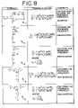
- FIG. 8is a plurality of simplified electrical circuit diagram, partially in block form, of various circuits for shifting the resonance frequency of a microphone output;
- FIG. 9is a simplified electrical circuit diagram, partially in block form, of a circuit to shift the resonance frequency of a microphone output
- FIG. 10is a plurality of graphs depicting the pattern variations between a pair of matched microphones at 500 Hz with ⁇ 10% variation in low frequency rolloff frequency at 50 Hz;
- FIG. 11is a plurality of graphs illustrating the pattern variations between a pair of matched microphones at 300 Hz with ⁇ 10% variation in low frequency rolloff frequency at 50 Hz;
- FIG. 12is a simplified electrical circuit diagram, partially in block for, of another circuit for shifting the low frequency rolloff of a pair of microphone outputs.
- FIG. 13is a plurality of graphs showing the improvement in directionality that is available with compensation, even when the compensation is imperfect.
- the present inventionincludes compensation to equalize the midband sensitivity M 0 .
- thiscan be done either in a sound box or in the sound field of a room. Alternatively, it can be done as a final step in the manufacturing process, during the fitting process, or as a “tune up” during a periodic checkup.
- the frequency content of the acoustic test signal used to equalize the midbandis confined to the flat portion of the sensitivity curve, which is generally near 1 kHz.
- an appropriate signalwould be a one-third octave noise band centered at 1 kHz.
- the gain adjustmentcan be implemented with a simple trimmer to adjust the gain.
- the gain valuecan be stored in memory and implemented in a programmable resistor. Each of these can also provide for periodic recalibration in the office of an audiologist.
- a very slow acting automatic gain controloperates on the output of one microphone to match its output to the level of the other.
- a block diagram 10 of such a systemis shown in FIG. 4 .
- the systemcan be mounted, for example, within a hearing aid housing and includes a front microphone 12 and a rear microphone 14 having respective outputs responsive to an audible input.
- a subtractor circuit 16is provided responsive to the front microphone output and the rear microphone output for producing a gain control output 18 .
- circuit 20In response to the front microphone output and the gain control output 18 , circuit 20 produces a gain compensated microphone output.
- the signal from each microphone 12 , 14is buffered and processed through a bandpass filter (“BPF”) 22 , 24 with a center frequency of approximately 1 kHz.
- BPFbandpass filter
- Each filtered signalis sent through an energy detector, such as an RMS detector 26 , 28 , and then a low pass filter 30 , 32 .
- the signalsrepresent the time average of the signal energy in each channel.
- These level estimatesare subtracted by circuit 16 to provide signal 18 proportional to the level difference between the microphone channels. This difference level is used to adjust the gain in one channel to better match the level of the other signal.
- the energy estimateswould be equal. Accordingly, the subtraction would give a zero output, and the compensating gain would remain unchanged. If the microphone sensitivity were to change, then an error signal would be generated at the output 18 of the subtraction circuitry 16 , and that error signal would change the gain in one channel to bring the two channels to equal output levels.
- the time constant of the AGC loopis long compared to the acoustic time delay between the signals from the two microphones, and long compared to the variability in level of speech.
- a time constant of 250 ms or greatercan be used.
- FIG. 3shows that the phase error extends an octave or more above the corner frequency.
- the low frequency rolloffbe below 100 Hz. This has other disadvantages, however.
- the low frequency responseallows significant low frequency acoustic noise from the environment to enter the microphone electronics. In some situations, this noise may saturate the low-level amplifiers. Once saturation occurs, electrical filters can no longer be used to remove the low frequency energy.
- a better solutionis to provide an electrical compensation circuitry to match the phase of the two microphones so it is not necessary to use a very low rolloff frequency.
- the primary advantage that comes with low frequency compensationis that the rolloff frequency can be accurately set at a specific frequency in the range of 150 to 250 Hz. If the two microphones are accurately matched after compensation, then good directionality is available throughout the low frequency range, and low frequency environmental noise will not corrupt the signals.
- the circuit of FIG. 5has the following transfer function:
- T ⁇ ( f )R + r R i ⁇ 1 + j ⁇ ⁇ ⁇ ⁇ Rr R + r ⁇ C 1 + j ⁇ ⁇ ⁇ ⁇ ⁇ r ⁇ ⁇ C
- T(f)can be made equivalent to Comp( ⁇ ) if:
- Ccan be chosen arbitrarily, and R i can be chosen independently to set the high frequency gain of the network.
- the circuit 34 within FIG. 5works only if ⁇ d is less that ⁇ l , in other words, the compensation circuit 34 can be used to lower the rolloff frequency, but not to raise it. Circuit 34 is only one example of many that can compensate the phase of a microphone. Other examples are discussed later herein.
- the circuit 34includes an input terminal 36 , for receiving an output from a hearing aid microphone or the like, and an amplifier 38 having an inverting input and an output. Connected to the output of the amplifier 38 and the inverting input is a feedback circuit that includes a feedback adjustment circuit 40 responsive to a rolloff control input. Further, a gain control circuit 42 is operably connected between the input terminal 36 and the inverting input of the amplifier 38 for adjusting the gain of the microphone output.
- Circuit 34can be used in a compensation system in the following way: The corner frequencies for low frequency rolloff for both of the two microphones are first measured. Then, the compensation circuit is applied to the microphone with the higher corner frequency to match it to the microphone with the lower frequency rolloff.
- the microphonescan be specified with a rolloff frequency that is slightly higher than the desired value in the final device such as a hearing aid.
- the compensation circuitcan be applied to both microphones to match their rolloff to the desired frequency.
- Measuring the rolloff frequencies of the two microphonescan effectively be accomplished in the above embodiments by using the facilities of an acoustic test box.
- an automated test systemcan be used to measure the frequency response of the two microphones and determine the component settings to achieve an adequate phase match.
- an automated method to perform the low frequency compensationis shown in FIG. 6 which also includes the magnitude compensator described above.
- the automated methodincludes a front microphone 12 and a back microphone 14 for producing respective outputs in response to an audible input. Responsive to the microphone outputs is a gain difference subtractor circuit 16 for producing a gain control output.
- a gain control circuit 42is provided that, in response to the front microphone output and the gain control output, produces a gain compensated microphone output 44 .
- Phase adjustment circuit 34is responsive to the gain compensated microphone output 44 and a rolloff control output 46 for producing a matching output 48 .
- the rolloff control outputis generated by a phase difference subtractor circuit 50 responsive to the matching output 48 and the back microphone output.
- the frequency compensation circuitassures that the 50 Hz response of the two microphones is the same.
- the sensitivity of the front microphone 12is modified to match that of the rear microphone 14 .
- the two signalsare again filtered, this time with a 50 Hz center frequency, where 50 Hz is assumed to be well below the low frequency rolloff of both microphones 12 , 14 . If the rolloff of the two microphones were the same, the filtered output of the two channels would have the same magnitude. Any difference in the levels is an indication that the rolloff frequencies are different. This difference is used to adjust the controlling resistor value in the rolloff compensator circuit 34 for the front microphone 12 .
- FIGS. 7 and 8Other examples of circuits that can be used to compensate the response are shown in FIGS. 7 and 8 .
- the primary advantage that comes with low frequency compensationis that the rolloff frequency may not be accurately set at a specific frequency in the range to 150 to 250 Hz. If the two microphones are accurately matched after compensation, then good directionality will be available throughout the low frequency range, and low frequency environmental noise will not corrupt the signals.
- H d ⁇ ( ⁇ )1 1 - ⁇ 2 ⁇ d 2 + j ⁇ ⁇ Q d ⁇ ⁇ d
- the transfer function of the compensation circuit needed to shift the resonance frequencyis
- FIG. 9depicts a circuit 60 for microphone resonance frequency shift compensation.
- the circuit 60includes an input terminal 62 for receiving an output from a microphone, and an amplifier 64 having an inverting input and an output. Connected to the output of the amplifier 64 and the inverting input is a feedback circuit 66 that includes a resistor R f , an inductor L f , and a C f that are connected to each other in parallel. Further, an input circuit 68 is operably connected between the input terminal 62 and the inverting input of the amplifier 64 for adjusting the gain of the circuit output 70 .
- circuit 60an all other circuits presented herein are simplified and may have stability problems if implemented exactly as shown. It is assumed that the designer will add whatever components necessary to assure stability.
- circuit 60 of FIG. 9has the following transfer function:
- T ⁇ ( ⁇ )- L f L ⁇ 1 - ⁇ 2 ⁇ LC + j ⁇ ⁇ ⁇ ⁇ L R 1 - ⁇ 2 ⁇ L f ⁇ C f + j ⁇ ⁇ ⁇ ⁇ L f R f
- circuits that can be used to compensate the high frequency responsesuch as, for example, those shown in FIG. 8 .
- Each of these circuitswould be employed with a different strategy to compensate the different responses between two microphones.
- two microphonesare used as a “matched” pair in a device such as a directional hearing aid.
- the microphonesare used to form a beam that is a cardioid in the free field.
- the directional patternis to remain “good” for frequencies down to at least 500 Hz, with good directionality as low as 300 Hz as a goal.
- we concentrate on the low frequency behaviorand thus assume that the resonance frequencies and Q values for the two microphones are identical.
- manufacturing tolerances on the microphonesare such that the rolloff frequency can be controlled to within ⁇ 10%.
- the patterns at 500 Hzare shown in FIG. 10 .
- the patterns at 300 Hzare shown in FIG. 11 .
- the performanceis clearly unacceptable at this frequency as the second polar shifts entirely to the backward direction.
- the low frequency rolloffcan only be controlled to ⁇ 10%, then adequate beam pattern control can be achieved at frequencies that are approximately a decade above the rolloff frequency.
- an objectiveis to use response compensation to achieve good directivity at 500 Hz using microphones whose low frequency rolloff varies by ⁇ 10% from a nominal value of 225 Hz.
- Another circuit 80 having the correct response for compensation of a pair of microphonesis shown in FIG. 12 .
- the strategyis to compensate each of the two microphones 82 , 83 to provide an output 84 , 85 , respectively, whose low frequency rolloff is at 250 Hz regardless of the uncompensated rolloff frequency. With sufficient resolution in the component values, this circuit 80 exactly compensates the difference in responses so that their frequency responses are identical.
- the population of microphones described aboveincludes samples with rolloff frequencies from approximately 200 Hz to 250 Hz.
- five compensation circuitscan be provided which exactly compensate the response of microphones whose rolloff frequencies are at 205 Hz, 215 Hz, 225 Hz, 235 Hz, and 245 Hz with each microphone connected to the compensation circuit that most closely matches its actual rolloff frequency.
- the maximum deviation from “ideal” compensationis ⁇ 5 Hz or ⁇ 21 ⁇ 2% in rolloff frequency.
- FIG. 13shows the improvement that is available with compensation, even when the compensation is imperfect.
- These polarsare calculated at 500 Hz, with the compensated rolloff frequency at 250 Hz.
- the compensationis perfect.
- the compensationis applied imperfectly; in each case, the microphones are compensated for a frequency that is in error by 5 Hz, and the error is in opposite directions for the two microphones.
- the polarshave reasonably good directivity even at a frequency that is only an octave above the (compensated) rolloff of the microphones.
- the method described herein for the compensation of low frequency rolloffis practically useful and can be implemented in the circuitry inside the microphone if the circuit values can be selected or trimmed to the proper values after the microphone is assembled. In such an embodiment, it is preferred that the low frequency rolloff be measured as a part of the final manufacturing process, and the circuit elements trimmed to the proper values for adequate compensation.
- an electrical circuitis examined to compensate for a manufacturing variation in the resonance frequency of a microphone.
- a microphonehas a desired resonance frequency of 6000 Hz, but its actual resonance frequency is 5% lower, or 5700 Hz.
- circuit 3 in FIG. 8is chosen, which reduces the number of reactive components compared to some of the other circuits of FIG. 8 , a value of 47 nF can be used for C.
- This valuewhile somewhat arbitrary, is the largest value that is conveniently available in a small package.
- the value of Lis calculated to resonate with C at the microphone resonance of 5700 Hz. This yields a value of 16.6 mH for L.
- C lis calculated to resonate with L at the desired frequency of 6000 Hz.
- the value of C lis 42.4 nF, and the value of C f is 433 nF.
- the 16 mH inductor and the 433 nF capacitormay be considered too large.
- An alternativewould be to use circuit 2 of FIG. 8 , which eliminates the larger capacitor. But this circuit needs a second inductor whose value is approximately 1.6 mH. Accordingly, in an embodiment, is it preferred that the functionality of the compensation circuits of FIG. 8 be implemented using synthetic inductors. This trades more practical reactive component values for additional active components.
- the high frequency performanceis improved by using a microphone with a resonance frequency that is above the frequency band that is important for directionality. If the resonance frequency is increased to the vicinity of 13 to 15 kHz, then good directionality is available to at least 10 kHz.
Landscapes
- Physics & Mathematics (AREA)
- Engineering & Computer Science (AREA)
- Acoustics & Sound (AREA)
- Signal Processing (AREA)
- Health & Medical Sciences (AREA)
- General Health & Medical Sciences (AREA)
- Otolaryngology (AREA)
- Neurosurgery (AREA)
- Circuit For Audible Band Transducer (AREA)
Abstract
Description
M(ω)=M0L(ω)H(ω)
where
- L(ω) models the low frequency rolloff, and
- H(ω) models the mid and high frequency behavior, including the diaphragm resonance.
where ωlis the corner frequency for the low frequency rolloff. The higher frequency behavior is approximated by:
where ωris the corner diaphragm resonance frequency and Q is the mechanical quality factor of that resonance.
M(ω)=M0L(ω)H(ω).
Claims (10)
Priority Applications (1)
| Application Number | Priority Date | Filing Date | Title |
|---|---|---|---|
| US10/425,143US7113604B2 (en) | 1998-08-25 | 2003-04-29 | Apparatus and method for matching the response of microphones in magnitude and phase |
Applications Claiming Priority (3)
| Application Number | Priority Date | Filing Date | Title |
|---|---|---|---|
| US9792698P | 1998-08-25 | 1998-08-25 | |
| US09/193,012US6654468B1 (en) | 1998-08-25 | 1998-11-16 | Apparatus and method for matching the response of microphones in magnitude and phase |
| US10/425,143US7113604B2 (en) | 1998-08-25 | 2003-04-29 | Apparatus and method for matching the response of microphones in magnitude and phase |
Related Parent Applications (1)
| Application Number | Title | Priority Date | Filing Date |
|---|---|---|---|
| US09/193,012DivisionUS6654468B1 (en) | 1998-08-25 | 1998-11-16 | Apparatus and method for matching the response of microphones in magnitude and phase |
Publications (2)
| Publication Number | Publication Date |
|---|---|
| US20030198356A1 US20030198356A1 (en) | 2003-10-23 |
| US7113604B2true US7113604B2 (en) | 2006-09-26 |
Family
ID=26793792
Family Applications (2)
| Application Number | Title | Priority Date | Filing Date |
|---|---|---|---|
| US09/193,012Expired - LifetimeUS6654468B1 (en) | 1998-08-25 | 1998-11-16 | Apparatus and method for matching the response of microphones in magnitude and phase |
| US10/425,143Expired - Fee RelatedUS7113604B2 (en) | 1998-08-25 | 2003-04-29 | Apparatus and method for matching the response of microphones in magnitude and phase |
Family Applications Before (1)
| Application Number | Title | Priority Date | Filing Date |
|---|---|---|---|
| US09/193,012Expired - LifetimeUS6654468B1 (en) | 1998-08-25 | 1998-11-16 | Apparatus and method for matching the response of microphones in magnitude and phase |
Country Status (4)
| Country | Link |
|---|---|
| US (2) | US6654468B1 (en) |
| EP (1) | EP0982971B1 (en) |
| DE (1) | DE69933627T2 (en) |
| DK (1) | DK0982971T3 (en) |
Cited By (11)
| Publication number | Priority date | Publication date | Assignee | Title |
|---|---|---|---|---|
| US20040022397A1 (en)* | 2000-09-29 | 2004-02-05 | Warren Daniel M. | Microphone array having a second order directional pattern |
| US20070258597A1 (en)* | 2004-08-24 | 2007-11-08 | Oticon A/S | Low Frequency Phase Matching for Microphones |
| US20080152167A1 (en)* | 2006-12-22 | 2008-06-26 | Step Communications Corporation | Near-field vector signal enhancement |
| US20080208538A1 (en)* | 2007-02-26 | 2008-08-28 | Qualcomm Incorporated | Systems, methods, and apparatus for signal separation |
| US20090022336A1 (en)* | 2007-02-26 | 2009-01-22 | Qualcomm Incorporated | Systems, methods, and apparatus for signal separation |
| US20090164212A1 (en)* | 2007-12-19 | 2009-06-25 | Qualcomm Incorporated | Systems, methods, and apparatus for multi-microphone based speech enhancement |
| US20090254338A1 (en)* | 2006-03-01 | 2009-10-08 | Qualcomm Incorporated | System and method for generating a separated signal |
| US20090299739A1 (en)* | 2008-06-02 | 2009-12-03 | Qualcomm Incorporated | Systems, methods, and apparatus for multichannel signal balancing |
| US20100054509A1 (en)* | 2008-08-29 | 2010-03-04 | Thompson Stephen C | Methods and apparatus for reduced distortion balanced armature devices |
| US20110069846A1 (en)* | 2009-09-21 | 2011-03-24 | Mediatek Inc. | Audio processing methods and apparatuses utilizing the same |
| US10616691B2 (en) | 2015-11-12 | 2020-04-07 | Knowles Electronics, Llc | Method and apparatus to increase audio band microphone sensitivity |
Families Citing this family (46)
| Publication number | Priority date | Publication date | Assignee | Title |
|---|---|---|---|---|
| US6278377B1 (en) | 1999-08-25 | 2001-08-21 | Donnelly Corporation | Indicator for vehicle accessory |
| US6654468B1 (en)* | 1998-08-25 | 2003-11-25 | Knowles Electronics, Llc | Apparatus and method for matching the response of microphones in magnitude and phase |
| CA2367579A1 (en)* | 1999-03-19 | 2000-09-28 | Siemens Aktiengesellschaft | Method and device for recording and processing audio signals in an environment filled with acoustic noise |
| EP1081985A3 (en)* | 1999-09-01 | 2006-03-22 | Northrop Grumman Corporation | Microphone array processing system for noisy multipath environments |
| US8682005B2 (en) | 1999-11-19 | 2014-03-25 | Gentex Corporation | Vehicle accessory microphone |
| US6882734B2 (en)* | 2001-02-14 | 2005-04-19 | Gentex Corporation | Vehicle accessory microphone |
| US7447320B2 (en)* | 2001-02-14 | 2008-11-04 | Gentex Corporation | Vehicle accessory microphone |
| US20010028718A1 (en) | 2000-02-17 | 2001-10-11 | Audia Technology, Inc. | Null adaptation in multi-microphone directional system |
| WO2001069968A2 (en)* | 2000-03-14 | 2001-09-20 | Audia Technology, Inc. | Adaptive microphone matching in multi-microphone directional system |
| US7116792B1 (en)* | 2000-07-05 | 2006-10-03 | Gn Resound North America Corporation | Directional microphone system |
| EP2348752A1 (en)* | 2000-09-29 | 2011-07-27 | Knowles Electronics, LLC | Second order microphone array |
| US6741714B2 (en) | 2000-10-04 | 2004-05-25 | Widex A/S | Hearing aid with adaptive matching of input transducers |
| EP1391138B1 (en)* | 2001-05-23 | 2005-09-28 | Phonak Ag | Method of generating an electrical output signal and acoustical/electrical conversion system |
| EP1351544A3 (en)* | 2002-03-08 | 2008-03-19 | Gennum Corporation | Low-noise directional microphone system |
| US7072482B2 (en) | 2002-09-06 | 2006-07-04 | Sonion Nederland B.V. | Microphone with improved sound inlet port |
| DE10310579B4 (en)* | 2003-03-11 | 2005-06-16 | Siemens Audiologische Technik Gmbh | Automatic microphone adjustment for a directional microphone system with at least three microphones |
| DE10310580A1 (en)* | 2003-03-11 | 2004-10-07 | Siemens Audiologische Technik Gmbh | Device and method for adapting hearing aid microphones |
| EP1629687A1 (en) | 2003-05-15 | 2006-03-01 | Oticon A/S | Microphone with adjustable properties |
| DE10327890A1 (en) | 2003-06-20 | 2005-01-20 | Siemens Audiologische Technik Gmbh | Method for operating a hearing aid and hearing aid with a microphone system, in which different directional characteristics are adjustable |
| US7424119B2 (en)* | 2003-08-29 | 2008-09-09 | Audio-Technica, U.S., Inc. | Voice matching system for audio transducers |
| DE102004010867B3 (en)* | 2004-03-05 | 2005-08-18 | Siemens Audiologische Technik Gmbh | Matching phases of microphones of hearing aid directional microphone involves matching second signal level to first by varying transition time of output signal from microphone without taking into account sound source position information |
| US7688985B2 (en)* | 2004-04-30 | 2010-03-30 | Phonak Ag | Automatic microphone matching |
| CA2581118C (en)* | 2004-10-19 | 2013-05-07 | Widex A/S | A system and method for adaptive microphone matching in a hearing aid |
| DK1773098T3 (en)* | 2005-10-06 | 2013-03-18 | Oticon As | Microphone customization system and method |
| JP2008278476A (en)* | 2007-04-05 | 2008-11-13 | Yamaha Corp | S/n ratio improvement method for condenser microphone, condenser microphone, and condenser microphone mounted device |
| JP5130895B2 (en)* | 2007-12-13 | 2013-01-30 | ソニー株式会社 | Audio processing apparatus, audio processing system, audio processing program, and audio processing method |
| US8275151B2 (en)* | 2007-12-19 | 2012-09-25 | Agere Systems Inc. | Speakerphone using adaptive phase rotation |
| US8724829B2 (en)* | 2008-10-24 | 2014-05-13 | Qualcomm Incorporated | Systems, methods, apparatus, and computer-readable media for coherence detection |
| US8229126B2 (en)* | 2009-03-13 | 2012-07-24 | Harris Corporation | Noise error amplitude reduction |
| US8620672B2 (en)* | 2009-06-09 | 2013-12-31 | Qualcomm Incorporated | Systems, methods, apparatus, and computer-readable media for phase-based processing of multichannel signal |
| WO2011044395A1 (en)* | 2009-10-09 | 2011-04-14 | National Acquisition Sub, Inc. | An input signal mismatch compensation system |
| US9648421B2 (en) | 2011-12-14 | 2017-05-09 | Harris Corporation | Systems and methods for matching gain levels of transducers |
| FR3018418B1 (en)* | 2014-03-04 | 2017-11-10 | Univ Maine | DEVICE AND METHOD FOR FILTERING THE RESONANCE PIC IN A POWER CIRCUIT OF AT LEAST ONE SPEAKER |
| FR3018419B1 (en)* | 2014-03-05 | 2017-06-23 | Univ Maine | DEVICE AND METHOD FOR FILTERING THE RESONANCE PIC IN A POWER SUPPLY CIRCUIT OF AT LEAST ONE SPEAKER BEFORE THE SAME |
| US10516935B2 (en) | 2015-07-15 | 2019-12-24 | Knowles Electronics, Llc | Hybrid transducer |
| US9843292B2 (en) | 2015-10-14 | 2017-12-12 | Knowles Electronics, Llc | Method and apparatus for maintaining DC bias |
| US10244333B2 (en)* | 2016-06-06 | 2019-03-26 | Starkey Laboratories, Inc. | Method and apparatus for improving speech intelligibility in hearing devices using remote microphone |
| US10477308B2 (en) | 2016-12-30 | 2019-11-12 | Sonion Nederland B.V. | Circuit and a receiver comprising the circuit |
| CN109218920B (en)* | 2017-06-30 | 2020-09-18 | 华为技术有限公司 | A signal processing method, device and terminal |
| JP2020036215A (en) | 2018-08-30 | 2020-03-05 | Tdk株式会社 | MEMS microphone |
| JP2020036214A (en) | 2018-08-30 | 2020-03-05 | Tdk株式会社 | MEMS microphone |
| US11062687B2 (en)* | 2019-01-04 | 2021-07-13 | Bose Corporation | Compensation for microphone roll-off variation in acoustic devices |
| US11303994B2 (en)* | 2019-07-14 | 2022-04-12 | Peiker Acustic Gmbh | Reduction of sensitivity to non-acoustic stimuli in a microphone array |
| WO2021021429A1 (en)* | 2019-07-31 | 2021-02-04 | Starkey Laboratories, Inc. | Ear-worn electronic device incorporating microphone fault reduction system and method |
| CN213586269U (en) | 2019-12-27 | 2021-06-29 | 楼氏电子(苏州)有限公司 | Acoustic receiver |
| DE102020200553B3 (en)* | 2020-01-17 | 2021-05-12 | Sivantos Pte. Ltd. | Method for matching the respective phase responses of a first microphone and a second microphone |
Citations (12)
| Publication number | Priority date | Publication date | Assignee | Title |
|---|---|---|---|---|
| US4412097A (en)* | 1980-01-28 | 1983-10-25 | Victor Company Of Japan, Ltd. | Variable-directivity microphone device |
| US4420655A (en) | 1980-07-02 | 1983-12-13 | Nippon Gakki Seizo Kabushiki Kaisha | Circuit to compensate for deficit of output characteristics of a microphone by output characteristics of associated other microphones |
| JPS5964994A (en) | 1982-10-05 | 1984-04-13 | Matsushita Electric Ind Co Ltd | microphone device |
| US4509022A (en) | 1982-03-01 | 1985-04-02 | U.S. Philips Corporation | Amplifier circuit with automatic gain control and hearing aid equipped with such a circuit |
| US4622440A (en) | 1984-04-11 | 1986-11-11 | In Tech Systems Corp. | Differential hearing aid with programmable frequency response |
| US4718099A (en)* | 1986-01-29 | 1988-01-05 | Telex Communications, Inc. | Automatic gain control for hearing aid |
| EP0509742A2 (en) | 1991-04-18 | 1992-10-21 | Matsushita Electric Industrial Co., Ltd. | Microphone apparatus |
| US5978490A (en) | 1996-12-27 | 1999-11-02 | Lg Electronics Inc. | Directivity controlling apparatus |
| US6035049A (en)* | 1997-09-05 | 2000-03-07 | Information Storage Devices, Inc. | AC coupling and signal amplification using switched capacitors |
| US6389142B1 (en) | 1996-12-11 | 2002-05-14 | Micro Ear Technology | In-the-ear hearing aid with directional microphone system |
| US6421448B1 (en)* | 1999-04-26 | 2002-07-16 | Siemens Audiologische Technik Gmbh | Hearing aid with a directional microphone characteristic and method for producing same |
| US6654468B1 (en)* | 1998-08-25 | 2003-11-25 | Knowles Electronics, Llc | Apparatus and method for matching the response of microphones in magnitude and phase |
- 1998
- 1998-11-16USUS09/193,012patent/US6654468B1/ennot_activeExpired - Lifetime
- 1999
- 1999-08-20DEDE69933627Tpatent/DE69933627T2/ennot_activeExpired - Lifetime
- 1999-08-20EPEP99306623Apatent/EP0982971B1/ennot_activeExpired - Lifetime
- 1999-08-20DKDK99306623Tpatent/DK0982971T3/enactive
- 2003
- 2003-04-29USUS10/425,143patent/US7113604B2/ennot_activeExpired - Fee Related
Patent Citations (13)
| Publication number | Priority date | Publication date | Assignee | Title |
|---|---|---|---|---|
| US4412097A (en)* | 1980-01-28 | 1983-10-25 | Victor Company Of Japan, Ltd. | Variable-directivity microphone device |
| US4420655A (en) | 1980-07-02 | 1983-12-13 | Nippon Gakki Seizo Kabushiki Kaisha | Circuit to compensate for deficit of output characteristics of a microphone by output characteristics of associated other microphones |
| US4509022A (en) | 1982-03-01 | 1985-04-02 | U.S. Philips Corporation | Amplifier circuit with automatic gain control and hearing aid equipped with such a circuit |
| JPS5964994A (en) | 1982-10-05 | 1984-04-13 | Matsushita Electric Ind Co Ltd | microphone device |
| US4622440A (en) | 1984-04-11 | 1986-11-11 | In Tech Systems Corp. | Differential hearing aid with programmable frequency response |
| US4718099B1 (en)* | 1986-01-29 | 1992-01-28 | Telex Communications | |
| US4718099A (en)* | 1986-01-29 | 1988-01-05 | Telex Communications, Inc. | Automatic gain control for hearing aid |
| EP0509742A2 (en) | 1991-04-18 | 1992-10-21 | Matsushita Electric Industrial Co., Ltd. | Microphone apparatus |
| US6389142B1 (en) | 1996-12-11 | 2002-05-14 | Micro Ear Technology | In-the-ear hearing aid with directional microphone system |
| US5978490A (en) | 1996-12-27 | 1999-11-02 | Lg Electronics Inc. | Directivity controlling apparatus |
| US6035049A (en)* | 1997-09-05 | 2000-03-07 | Information Storage Devices, Inc. | AC coupling and signal amplification using switched capacitors |
| US6654468B1 (en)* | 1998-08-25 | 2003-11-25 | Knowles Electronics, Llc | Apparatus and method for matching the response of microphones in magnitude and phase |
| US6421448B1 (en)* | 1999-04-26 | 2002-07-16 | Siemens Audiologische Technik Gmbh | Hearing aid with a directional microphone characteristic and method for producing same |
Cited By (18)
| Publication number | Priority date | Publication date | Assignee | Title |
|---|---|---|---|---|
| US7471798B2 (en)* | 2000-09-29 | 2008-12-30 | Knowles Electronics, Llc | Microphone array having a second order directional pattern |
| US20040022397A1 (en)* | 2000-09-29 | 2004-02-05 | Warren Daniel M. | Microphone array having a second order directional pattern |
| US20070258597A1 (en)* | 2004-08-24 | 2007-11-08 | Oticon A/S | Low Frequency Phase Matching for Microphones |
| US8898056B2 (en) | 2006-03-01 | 2014-11-25 | Qualcomm Incorporated | System and method for generating a separated signal by reordering frequency components |
| US20090254338A1 (en)* | 2006-03-01 | 2009-10-08 | Qualcomm Incorporated | System and method for generating a separated signal |
| US20080152167A1 (en)* | 2006-12-22 | 2008-06-26 | Step Communications Corporation | Near-field vector signal enhancement |
| US8160273B2 (en) | 2007-02-26 | 2012-04-17 | Erik Visser | Systems, methods, and apparatus for signal separation using data driven techniques |
| US20080208538A1 (en)* | 2007-02-26 | 2008-08-28 | Qualcomm Incorporated | Systems, methods, and apparatus for signal separation |
| US20090022336A1 (en)* | 2007-02-26 | 2009-01-22 | Qualcomm Incorporated | Systems, methods, and apparatus for signal separation |
| US8175291B2 (en) | 2007-12-19 | 2012-05-08 | Qualcomm Incorporated | Systems, methods, and apparatus for multi-microphone based speech enhancement |
| US20090164212A1 (en)* | 2007-12-19 | 2009-06-25 | Qualcomm Incorporated | Systems, methods, and apparatus for multi-microphone based speech enhancement |
| US20090299739A1 (en)* | 2008-06-02 | 2009-12-03 | Qualcomm Incorporated | Systems, methods, and apparatus for multichannel signal balancing |
| US8321214B2 (en) | 2008-06-02 | 2012-11-27 | Qualcomm Incorporated | Systems, methods, and apparatus for multichannel signal amplitude balancing |
| US20100054509A1 (en)* | 2008-08-29 | 2010-03-04 | Thompson Stephen C | Methods and apparatus for reduced distortion balanced armature devices |
| US8385583B2 (en) | 2008-08-29 | 2013-02-26 | The Penn State Research Foundation | Methods and apparatus for reduced distortion balanced armature devices |
| US20110069846A1 (en)* | 2009-09-21 | 2011-03-24 | Mediatek Inc. | Audio processing methods and apparatuses utilizing the same |
| US8731210B2 (en)* | 2009-09-21 | 2014-05-20 | Mediatek Inc. | Audio processing methods and apparatuses utilizing the same |
| US10616691B2 (en) | 2015-11-12 | 2020-04-07 | Knowles Electronics, Llc | Method and apparatus to increase audio band microphone sensitivity |
Also Published As
| Publication number | Publication date |
|---|---|
| EP0982971B1 (en) | 2006-10-18 |
| EP0982971A3 (en) | 2001-04-18 |
| DE69933627T2 (en) | 2007-08-23 |
| US6654468B1 (en) | 2003-11-25 |
| DE69933627D1 (en) | 2006-11-30 |
| US20030198356A1 (en) | 2003-10-23 |
| EP0982971A2 (en) | 2000-03-01 |
| DK0982971T3 (en) | 2007-01-08 |
Similar Documents
| Publication | Publication Date | Title |
|---|---|---|
| US7113604B2 (en) | Apparatus and method for matching the response of microphones in magnitude and phase | |
| US6421448B1 (en) | Hearing aid with a directional microphone characteristic and method for producing same | |
| US8374366B2 (en) | System and method for adaptive microphone matching in a hearing aid | |
| US5029215A (en) | Automatic calibrating apparatus and method for second-order gradient microphone | |
| EP1068773B1 (en) | Apparatus and methods for combining audio compression and feedback cancellation in a hearing aid | |
| CA1230828A (en) | Digital graphic equalizer | |
| US6072884A (en) | Feedback cancellation apparatus and methods | |
| US6272229B1 (en) | Hearing aid with adaptive matching of microphones | |
| US6219427B1 (en) | Feedback cancellation improvements | |
| US7289637B2 (en) | Method for automatically adjusting the filter parameters of a digital equalizer and reproduction device for audio signals for implementing such a method | |
| US20050276423A1 (en) | Method and device for receiving and treating audiosignals in surroundings affected by noise | |
| US7324649B1 (en) | Hearing aid device, comprising a directional microphone system and a method for operating a hearing aid device | |
| DE60012316T2 (en) | PROGRAMMABLE MULTI-MODE, MULTI-MICROPHONE SYSTEM | |
| US4052560A (en) | Loudspeaker distortion reduction systems | |
| US4109107A (en) | Method and apparatus for frequency compensation of electro-acoustical transducer and its environment | |
| KR100260224B1 (en) | Howling preventing apparatus | |
| US5406633A (en) | Hearing aid with permanently adjusted frequency response | |
| US7003124B1 (en) | System and method for adjusting frequency response characteristics of high-pass crossovers supplying signal to speakers used with subwoofers | |
| US7254245B2 (en) | Circuit and method for adaptation of hearing device microphones | |
| US4145664A (en) | Audio signal compression and expansion system | |
| US5625698A (en) | Loudspeaker and design methodology | |
| US20040096067A1 (en) | Sound reproducing system | |
| EP0567061A1 (en) | Method and system for reproducing audio frequencies | |
| KR940002303B1 (en) | Electronic graphic equalizer automatic volume control device and control method | |
| JPS6216031Y2 (en) |
Legal Events
| Date | Code | Title | Description |
|---|---|---|---|
| AS | Assignment | Owner name:KNOWLES ELECTRONICS, LLC, ILLINOIS Free format text:ASSIGNMENT OF ASSIGNORS INTEREST;ASSIGNOR:THOMPSON, STEPHEN C.;REEL/FRAME:014676/0017 Effective date:20030911 | |
| AS | Assignment | Owner name:JPMORGAN CHASE BANK AS ADMINISTRATIVE AGENT, NEW Y Free format text:SECURITY INTEREST;ASSIGNOR:KNOWLES ELECTRONICS LLC;REEL/FRAME:015469/0426 Effective date:20040408 Owner name:JPMORGAN CHASE BANK AS ADMINISTRATIVE AGENT,NEW YO Free format text:SECURITY INTEREST;ASSIGNOR:KNOWLES ELECTRONICS LLC;REEL/FRAME:015469/0426 Effective date:20040408 | |
| REMI | Maintenance fee reminder mailed | ||
| FPAY | Fee payment | Year of fee payment:4 | |
| SULP | Surcharge for late payment | ||
| FEPP | Fee payment procedure | Free format text:PAYOR NUMBER ASSIGNED (ORIGINAL EVENT CODE: ASPN); ENTITY STATUS OF PATENT OWNER: LARGE ENTITY | |
| FPAY | Fee payment | Year of fee payment:8 | |
| AS | Assignment | Owner name:KNOWLES ELECTRONICS HOLDINGS, INC., ILLINOIS Free format text:RELEASE BY SECURED PARTY;ASSIGNOR:JP MORGAN CHASE BANK N.A.;REEL/FRAME:041108/0474 Effective date:20050927 | |
| FEPP | Fee payment procedure | Free format text:MAINTENANCE FEE REMINDER MAILED (ORIGINAL EVENT CODE: REM.) | |
| LAPS | Lapse for failure to pay maintenance fees | Free format text:PATENT EXPIRED FOR FAILURE TO PAY MAINTENANCE FEES (ORIGINAL EVENT CODE: EXP.); ENTITY STATUS OF PATENT OWNER: LARGE ENTITY | |
| STCH | Information on status: patent discontinuation | Free format text:PATENT EXPIRED DUE TO NONPAYMENT OF MAINTENANCE FEES UNDER 37 CFR 1.362 | |
| FP | Lapsed due to failure to pay maintenance fee | Effective date:20180926 |