US7113124B2 - Centerline and depth locating method for non-metallic buried utility lines - Google Patents
Centerline and depth locating method for non-metallic buried utility linesDownload PDFInfo
- Publication number
- US7113124B2 US7113124B2US10/997,729US99772904AUS7113124B2US 7113124 B2US7113124 B2US 7113124B2US 99772904 AUS99772904 AUS 99772904AUS 7113124 B2US7113124 B2US 7113124B2
- Authority
- US
- United States
- Prior art keywords
- line
- locator
- depth
- centerline
- gpr
- Prior art date
- Legal status (The legal status is an assumption and is not a legal conclusion. Google has not performed a legal analysis and makes no representation as to the accuracy of the status listed.)
- Expired - Lifetime
Links
Images


Classifications
- G—PHYSICS
- G01—MEASURING; TESTING
- G01V—GEOPHYSICS; GRAVITATIONAL MEASUREMENTS; DETECTING MASSES OR OBJECTS; TAGS
- G01V3/00—Electric or magnetic prospecting or detecting; Measuring magnetic field characteristics of the earth, e.g. declination, deviation
- G01V3/12—Electric or magnetic prospecting or detecting; Measuring magnetic field characteristics of the earth, e.g. declination, deviation operating with electromagnetic waves
- Y—GENERAL TAGGING OF NEW TECHNOLOGICAL DEVELOPMENTS; GENERAL TAGGING OF CROSS-SECTIONAL TECHNOLOGIES SPANNING OVER SEVERAL SECTIONS OF THE IPC; TECHNICAL SUBJECTS COVERED BY FORMER USPC CROSS-REFERENCE ART COLLECTIONS [XRACs] AND DIGESTS
- Y02—TECHNOLOGIES OR APPLICATIONS FOR MITIGATION OR ADAPTATION AGAINST CLIMATE CHANGE
- Y02A—TECHNOLOGIES FOR ADAPTATION TO CLIMATE CHANGE
- Y02A90/00—Technologies having an indirect contribution to adaptation to climate change
- Y02A90/30—Assessment of water resources
Definitions
- Embodiments of the present inventionrelate to tracking of concealed non-metallic underground utilities using a pipe and cable locator outfitted with ground penetrating radar and an inertial navigation device.
- Utility conduitsare often buried underground and not readily accessible. It is often necessary to locate these concealed utility conduits in order to repair and replace them. It is also important to know the location of utility conduits in order to avoid them while excavating an area. Examples of hidden utility conduits include pipelines for gas, sewage, or water and cables for telephone, television or power.
- Line locatorsThere are various ways to locate concealed objects, for example, using pipe and cable locators, also known as line locators.
- Conventional line locatorsare appropriate when seeking electrically conductive objects, such as metallic pipelines and cables.
- Line locatorsmay also be used for finding non-electrically conducting conduits when the conduit is marked with a conducting trace wire or trace tape buried along the conduit.
- the process of applying an AC signal to the conductor at an accessible point and detecting the resulting electromagnetic radiationis well known in the art. When an AC signal is applied, the conductor acts as an antenna radiating an electromagnetic field along its entire length.
- a fully digital implementation of an electromagnetic line locatoris disclosed in U.S. patent application Ser. No. 10/622,376, “Method and Apparatus for Digital Detection of Electromagnetic Signal Strength and Signal Direction in Metallic Pipes and Cables”, by James W. Waite and Johan D. ⁇ verby.
- a line locator used above grounddetects electromagnetic emissions from conductors underground.
- a disadvantage with relying solely on the line locator deviceis that it may fail to identify and distinguish among various utility conduits and conductors, especially non-conductive lines, such as, for example, gas lines, fiber optic lines and plastic water lines when not marked with trace wires.
- ground penetrating radarsystems have been used for utility locating applications.
- GPRground penetrating radar
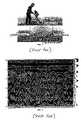
- FIG. 1Several commercial systems exist, an example of which is shown in FIG. 1 . All such systems present to the user a fairly complex grey-scale or color image of the radar pulse echo amplitude in a 2-D map of depth vs. horizontal ground position.
- This type of displayan example of which is shown in FIG. 2 , is useful in survey and mapping applications, but provides far too much information for the ordinary user trained in line location techniques. In such existing systems, the results that signify the presence of underground utility lines are often not available until after post processing the image on a computer.
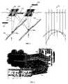
- Dipole antenna assembly 301is moved across the ground in the direction of path 304 .
- Transmit “bowtie” antenna 302couples a radar pulse 307 into the ground and receive bowtie antenna 303 receives a reflected signal 308 .
- Utility lines 309 and 310represent discontinuities in the dielectric constant of the soil medium, thus reflections occur and the lines can be discriminated from the background.
- Sequence of traces 311represent an example of the radar return from lines 309 , 310 , and by viewing the entire sequence one can deduce the presence of an underground object.
- the aggregate imageoften takes the form of the series of overlapping hyperbolas seen in FIG. 2 .
- Subsequent path directions 305 , 306are surveyed to fill in a large matrix of radar echo data.
- a second set of pathsare mapped which are orthogonal to paths 304 , 305 , 306 , resulting in a 2-D grid of path directions.
- Electromagnetic (EM) line locator user interfacesare designed for infrequent use.
- the locate technicianmust be able to pick up the instrument after sporadic use and be able to track a specific line though an unfamiliar area.
- the line locationis often marked with paint and must have accuracy within accepted (and sometimes legal) guidelines.
- the images of the reflected GPR signals shown in FIG. 2though appearing static in the figure, constantly change when the user is walking the locator down the line.
- Featuresare often inconsistent and unrecognizable when these maps are presented in real-time. Using conventional methods without off-line image processing, centerline errors that are only a few centimeters for electromagnetically traced lines would not be achievable for a GPR tracked line.
- Depth of the target utility lineis an important parameter in any locating task. This is because the locate operation often precedes a digging operation, and the result of the locate determines how deep a backhoe operator can dig without impacting the utility line.
- prior art GPR systemsmust be calibrated by locating a known underground object on the same test site (since soil conditions must be identical between the calibration and the locate), and then digging down to the object to determine the exact depth. Without this absolute depth confirmation, GPR systems rely on a user-specified choice of the dielectric constant of the soil at the test site. This is often difficult at best, and depth determinations are subject to 20% tolerances in this scenario.
- a dual mode line locatorthat combines conventional electromagnetic line locator techniques with ground penetrating radar (GPR), allowing accurate real-time tracking of position and depth for both metallic and non-metallic lines. More specifically a signal processing method is described to allow real-time line tracking in the GPR mode, which relies on range data (echo signals) from the radar system as well as dual-axis accelerometers for inertial tracking purposes.
- the preferred embodimentcombines the GPR sensor inputs with a signal processing system and display device that emulates the user interface and tracking capabilities of traditional metallic pipe and cable locators.
- the preferred embodimentallows the visual presentation of signal strength, left/right line deviation, and line guidance in substantially the same visual elements that guide a user during the tracking of metallic lines using electromagnetic methods.
- This disclosed methodmaps the radar range data, combined with position information from inertial sensors, through a multi-order Kalman filter, enabling a smooth predicted path of the non-metallic line based on measured data and physical models.
- this methodcan stand alone and be implemented on GPR-only locating systems, the preferred embodiment takes advantage of the dual-mode aspect of the invention and enhances the depth accuracy of GPR systems using electromagnetic (EM) line locator measurements made during calibration.
- EMelectromagnetic
- the inventionalso makes use of the EM locator's independent (and quite accurate) depth measurement capability to accurately deduce the radar signal velocity and hence the dielectric constant of the soil in the immediate vicinity of the GPR based non-metallic line locates. Since the radar signal time delay to target is directly proportional to the velocity of propagation of the radar signal in the soil, the present invention leads to better GPR-based location accuracy (both centerline and depth) when the velocity (and hence the radar echo return time) is correctly calibrated by the EM system.
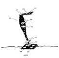
- FIG. 1shows an operator using a prior art GPR system to collect radar signals for later analysis and post-processing.
- FIG. 2is an example of the radar echo signal map that appears on displays of prior art GPR utility survey systems.
- the horizontal axisis linear position on the ground, and the vertical axis is depth.
- FIG. 3is a pictorial view of a single GPR antenna assembly moving over the ground, which contains separate bowtie transmit and receive antennas. A set of scans of the radar signal echo is shown for the traverse of one path using the GPR system.
- FIG. 4shows the result of a post-processing operation in which radar scans from multiple paths are organized and presented in a 3-D pictorial of the detected subsurface utility lines.
- FIG. 5shows one embodiment of a dual mode line locator, combining electromagnetic and ground penetrating radar location methods.
- FIG. 6is a typical user interface for a conventional electromagnetic line locator.
- FIG. 7is one embodiment of the user interface for a dual mode line locator, when in GPR mode.
- FIG. 7Ais a static view of the radar range data used to establish a fix on the line to be tracked, while the dynamic tracking and line location screen is shown below in FIG. 7B .
- FIG. 8demonstrates the preferred mode of use in GPR tracking mode.
- the userwalks down the line swinging the GPR antenna assembly to the left and right of the line, monitoring the centerline and depth in real-time.
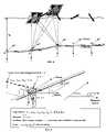
- FIG. 9represents the geometry of the GPR tracking application.
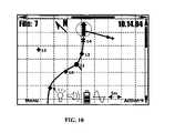
- FIG. 10shows one embodiment of a 2-D map view that presents a bird's eye view of the tracked utility line.
- Line locator 500 in FIG. 5offers both EM and GPR location methods and thus is a dual mode locator for both metallic and non-metallic utility lines. Out of view of the locate technician operating locator 500 is a buried utility line. If an active EM signal from a transmitter (not shown) has energized the line, the induced magnetic field is essentially concentric and five coils 503 (bottom reference), 505 (left/right, includes two coils), 504 (top), and 506 (guidance) generate received signals that are processed using the methods previously disclosed in U.S. patent application Ser. No. 10/622,376, which is herein incorporated by reference in its entirety.
- Display 501 and speaker 507alert the user to the signal strength, left/right deviation from centerline, depth to the conducting line, and a preview of any upcoming turns in the line (using a guidance compass display 604 , FIG. 6 ).
- the depthis calculated by the ratio of signal levels between the top and bottom coils, using an algorithm described in U.S. patent application Ser. No. 10/189,342, “Detecting Field Distortion In Underground Line Location”, by Russell N. Bigelow, which is herein incorporated by reference in its entirety.
- the depth accuracyis better than 5% using this method, up to about 4 meters for reasonable signal levels.
- the userinteracts with the battery operated, handheld locator via hard-key and pointing device 502 , which is also used to switch between EM and GPR modes.
- GPR modethe aforementioned coils 503 , 505 , 504 , and 506 are normally inactive, since the GPR tracked line is assumed to be non-metallic. However this doesn't have to be the case, if processing power is not an issue.
- transmit antenna 508 and receive antenna 509are active in GPR mode, with common DSP based processing electronics present within the locator body 500 .
- bowtie antenna 508 , 509are normally made of copper foil, little interference effect is seen by the EM coils 503 , 505 , 504 , and 506 . This is because an energized line creates a concentric magnetic field around the conductor according to the right hand rule, and thus all the EM coils are exposed to maximum signal when the locator is aligned along the line to be tracked. Note for the configuration highlighted in FIG. 5 , the maximum EM strength signal results when the bowtie antennas are directly positioned over the centerline. In GPR mode, this will also turn out to be the case.
- a primary display elementis the “proportional left-right” bar 601 that provides the user real-time feedback on how far off the centerline is the locator.
- the locatorIn normal operation the locator is swung left-right-left at a rate of about 1 Hz, and the vertical bar travels side-to-side with little perceptible latency.
- the degree of divergence of the baris proportional to the distance from the centerline. Typical side-to-side travel distances are about 1 ⁇ 4 to 1 ⁇ 2 meter peak excursion, depending on depth (more excursion for larger depths). Even an excursion of a few centimeters can result in perceptible travel of the vertical bar.
- Depth 602is continuously displayed, and is the result of the calculation mentioned above. The calculation is invoked on data collected only when the locator is at the centerline. Thus new depth estimates are available at about a 1 Hz rate based on the swing frequency used by the locator technician.
- Signal Direction indicator 605presents feedback of the detected direction of current flow in the tracked line, and provides the EM locator technician an alert that the signal may have been subject to capacitive bleed-over to adjacent conductors.
- Bar graph and numeric readout 603presents the Signal Strength measurement, and is also used to determine the centerline position. The concentric field lines emanating from the conductor result in maximum coil 503 , 504 output at centerline, and fall off toward the side. The rate at which this occurs again depends on depth (reduced fall off with increased depth).
- Guidance compass display 604presents a preview of a direction change in the tracked line, and derives its benefits from a forward facing coil on the locator 506 .
- this coil's signalis compared to the bottom reference coil 503 , a left or right heading change can be detected in advance of when the left/right display indicates a departure from centerline.
- the remainder of features present on the EM line locator interface in FIG. 6include the display of the active transmitter frequency 607 , the measured current in the line 606 , and an Earth compass heading 609 that points to true north after magnetic declination corrections. It is used in the generation of absolute coordinates and to align mapped line locate displays to the actual environment. Icons 608 and 610 indicate the active connection to a GPS receiver and the presence of a buried marker, respectively.
- a fully digital implementation of an electronic marker locator that could coexist with the present inventionis described in U.S. patent application Ser. No. 10/759747, “Method and Apparatus for Digital Detection of Electronic Markers Using Frequency Adaptation”, by Johan D. ⁇ verby and James W. Waite, which is incorporated by reference into this disclosure.
- the user interfaceis very similar. After depth calibration (described below), the user must establish a fix on the target prior to “walking the line”. Normally this happens just as for an EM locate, by traversing the area looking for a L/R deflection of bar 601 . Many times a line must be tracked from a known source. For example, plastic water pipes are commonly used for irrigation systems, but these pipes generally terminate at a known distribution location. A reasonable tracking approach is to begin at the known location, establish a fix, and then begin walking the line while monitoring the left/right deflection.
- FIG. 7Ais a busy presentation indicative of several buried pipes in the top 2 meters of soil, it is a repeatable measurement along a single axis—the user does not walk forward until the signature hyperbola is denoted as the line to be tracked.
- some embodiments of the locator user interfaceallows switching between the two views shown in FIGS. 7A and 7B easily, online as data is being measured and displayed.
- the white arrow 701 in 7 Acan be dragged to the hyperbola that represents the line to be fixed as the “tracked line”.
- the FIG. 7B displaycan be selected, and the left/right swinging motion invoked in order to validate that the locator has a lock on the line using a combination of physical models, measured data, and an optimal multi-order Kalman filter.
- the Kalman filter operationsboth predict the next expected line position and correct for the current one. These filters are described in detail below, after the calibration and inertial sensing systems are exposed. Residual errors in the detection process are monitored online to detect when the locator has lost the lock, as can occur when the line makes a sharp turn at an elbow joint, for instance. At this point the user can return to the “Establish Fix” display ( FIG. 7A ) and manually sweep the locator through the test field from the known position of the last lock. Tracking can proceed once a reorientation of the locator along the new direction has occurred, and the user has reselected a new hyperbola apex as the line of interest.
- the primary display screenis used to maintain the lock on the tracked line.
- One such embodiment of this interfaceis represented by FIG. 7B . Notice that the pertinent EM line locate display features are also present in the GPR display, including the left/right proportional display, the guidance compass, the signal strength, and Earth's compass heading to true north.
- the EM line locatoris used to determine the depth of a metallic line in the vicinity of the non-metallic lines to be traced.
- the vicinitycan be defined as any region for which the soil dielectric constant is essentially similar.
- the chosen metallic lineis energized with a standard narrowband EM locate signal, either by direct or inductive coupling, and the locator is used to calculate depth per the procedure referenced above. Depth calculations can be done with very high accuracy when the signal level is high, for example when the receiver is not too far away from the point of signal injection.
- the GPR modeis made active. Since a metal line is a very reflective target, a single radar ping will result in a strong return from the target line. Multiple pings can be averaged together to reduce background noise.
- a threshold operationcan be used to detect the elapsed time to the target from return signal. Since this is the same target as from the EM locator depth operation, it has known depth. Therefore to calibrate the GPR system, the two-way travel time (2T) for that target is used to calculate the radar signal velocity:
- v2 ⁇ ( depth 2 ⁇ T ) ( EQN . ⁇ 1 )
- Typical GPR signal velocitiesrange from a few centimeters per nanosecond up to about 25 cm/ns.
- the velocity vis stored after calibration for subsequent use, including the measurement of unknown depths given the two-way travel time. In the physical models developed below, v is taken as a constant. Any changes in soil dielectric constant (and thus v) that occur over the test field are included in the noise model.
- the GPR modeis ready to track lines that are not known in position or depth.
- trackingcan begin. In FIG. 8 , this procedure is highlighted.
- the locator 500 with GPR antenna assembly 301is moved down the line in a lazy zig-zag pattern, crossing the line an additional four times after the starting position (denoted position zero in FIG. 8 ).
- the incident angle (angle of attack) of each crossingis not important, but is controllable by the user based on the responsiveness of the locator left/right display.
- the operatorgains more precise feedback of the centerline position by taking the locator off-line to force deflection of the left/right indication 601 .
- a 2-axis inertial accelerometer sensoris mounted in the foot of the locator so that deflections of the GPR antenna assembly are measurable by double integration, both from centerline of the tracked utility and in an absolute sense.
- a line locator that includes such a sensoris described in U.S. patent application Ser. No. 10/407,705 “Buried Line Locator with Integral Position Sensing”, by Gordon Pacey and assigned to Metrotech Corporation, which is herein incorporated by reference in its entirety.
- the integrationsare reset at each centerline crossing.
- absolute x, y position fixesare made at every centerline crossing, and the accelerometer system provides a relative position of the GPR antenna assembly until the next centerline crossing.
- Position zero (the start of the GPR tracking operation) in FIG. 8is taken as the point x ⁇ 0, y ⁇ 0, z ⁇ 0. If a connection to a GPS receiver is active, this point can be associated with a latitude and longitude.
- Position determinations of the tracked lineare made at each crossing (points 1 , 2 , 3 , 4 in FIG. 8 ), and result in an array of absolute measurements of x line and y line .
- the quantity z lineis always referenced from ground level, though an alternative embodiment could consider depth of the line an absolute quantity as well, referenced in Earth coordinates.
- the x directionis arbitrarily chosen to correspond to true north, and thus the y direction points to west. This convention is only important when the tracked line is presented on a map display, such that the map can be oriented with the local geography.
- the locatoralso has a 3-axis magnetometer (compass sensor) aboard that measures the magnetic declination ⁇ at each logged centerline point.
- the GPR antenna assemblyis kept close to the ground to ensure adequate coupling of the transmitted energy.
- Two-way travel time measurementsare performed at a rate roughly equal to every centimeter (or less) of the targeted line.
- This scan ratewill generally support the acquisition of 1024 samples per scan, for a total sampling requirement of 85 kHz.
- the depth sampling intervalis then 0.4 cm.
- one who is trained in the art of GPR system designcan modify the parameters described in this example to configure the system in other ways appropriate to the depth range and target of interest.
- the GPR signalis acquired and the two-way travel time to the target is determined. If we denote half this quantity by t (the one-way travel time), then with the developments noted in the preceding paragraphs we have established real-time measurements of ⁇ umlaut over (x) ⁇ , ⁇ , t, ⁇ are available at every scan (for example, at a rate of 83 Hz), as the locator is moved back and forth over the line while the user is walking forward and monitoring the left/right indication.
- the predicted value uis as graphically depicted in FIG. 9 . For every scan at known z, a travel time t multiplied by the velocity v results in a prediction of the perpendicular off-axis distance u.
- a multi-order Kalman filteris designed that predicts the model state, consisting of the parameters x, y, z, x line , y line , z line , ⁇ line , u, v, ⁇ , ⁇ dot over ( ⁇ ) ⁇ , ⁇ , ⁇ dot over ( ⁇ ) ⁇ , ⁇ , and subsequently corrects the measured values ⁇ umlaut over (x) ⁇ , ⁇ , t, ⁇ .
- the tracking methodto result in a “hyperbola locked condition”, during which the off-axis distance u is predicted on every scan step (at an 83 Hz rate, for example).
- This state valuecompared to the relative excursion of x and y as derived from the inertial sensors, forms the value that is presented to the user in the left/right deflection indication 601 .
- the data vector x line , y line , z line , ⁇ dot over ( ⁇ ) ⁇is logged to the locator memory at each centerline crossing. If a GPS receiver is active, the GPS coordinates can also be logged, as well as a date and time stamp.
- a 2-D Map View shown in FIG. 10is an alternative presentation available to the user for selection at any time.
- a green cursormarks the current locator position, but all previously logged data vectors are displayed on the map.
- the Guide Compass and Earth Compasscollaborate to show the absolute relationship between the line direction and the local geography.
- the combination of the located centerline, a dual axis accelerometer and link to a pocket GPS system (Bluetooth enabled)establish the user's current position on the map.
- the accelerometer based tracking algorithmmeasures the travel distance and direction relative to magnetic north, plotting the path traveled and actual reference point position.
- the userreturns by walking to the last position on-centerline.
- the accelerometer tracking systemwill move the cursor to roughly the correct position on the map, but if a small deviation exists the pointing device 502 can be used to position it correctly.
- the “hyperbola lock”is reestablished, and normal line tracing can resume.
- WaypointsObjects whose GPS coordinates are known are collectively termed Waypoints.
- the usercan download any number of Waypoints (up to memory limits, of course) to the locator.
- Waypointsare displayed on the Map View whenever the current position and map scale are inclusive of the Waypoint(s).
Landscapes
- Physics & Mathematics (AREA)
- Engineering & Computer Science (AREA)
- Remote Sensing (AREA)
- Life Sciences & Earth Sciences (AREA)
- Electromagnetism (AREA)
- Environmental & Geological Engineering (AREA)
- Geology (AREA)
- General Life Sciences & Earth Sciences (AREA)
- General Physics & Mathematics (AREA)
- Geophysics (AREA)
- Geophysics And Detection Of Objects (AREA)
Abstract
Description
Typical GPR signal velocities range from a few centimeters per nanosecond up to about 25 cm/ns. The velocity v is stored after calibration for subsequent use, including the measurement of unknown depths given the two-way travel time. In the physical models developed below, v is taken as a constant. Any changes in soil dielectric constant (and thus v) that occur over the test field are included in the noise model.
u=√{square root over (v2t2−z2)} (EQN. 2),
where v is the calibrated radar signal velocity, t is the one-way travel time (determined by division by two of the measured two-way travel time to the target and a threshold operation), and z is the depth of the target line from the surface. The predicted value u is as graphically depicted in
Claims (2)
Priority Applications (3)
| Application Number | Priority Date | Filing Date | Title |
|---|---|---|---|
| US10/997,729US7113124B2 (en) | 2003-11-25 | 2004-11-23 | Centerline and depth locating method for non-metallic buried utility lines |
| PCT/US2005/027240WO2006015310A2 (en) | 2004-07-29 | 2005-07-29 | Sensor fusion for model-based detection in pipe and cable locator systems |
| US11/193,100US7834801B2 (en) | 2003-11-25 | 2005-07-29 | Sensor fusion for model-based detection in pipe and cable locator systems |
Applications Claiming Priority (2)
| Application Number | Priority Date | Filing Date | Title |
|---|---|---|---|
| US52529103P | 2003-11-25 | 2003-11-25 | |
| US10/997,729US7113124B2 (en) | 2003-11-25 | 2004-11-23 | Centerline and depth locating method for non-metallic buried utility lines |
Related Child Applications (1)
| Application Number | Title | Priority Date | Filing Date |
|---|---|---|---|
| US11/193,100Continuation-In-PartUS7834801B2 (en) | 2003-11-25 | 2005-07-29 | Sensor fusion for model-based detection in pipe and cable locator systems |
Publications (2)
| Publication Number | Publication Date |
|---|---|
| US20050156776A1 US20050156776A1 (en) | 2005-07-21 |
| US7113124B2true US7113124B2 (en) | 2006-09-26 |
Family
ID=34752958
Family Applications (1)
| Application Number | Title | Priority Date | Filing Date |
|---|---|---|---|
| US10/997,729Expired - LifetimeUS7113124B2 (en) | 2003-11-25 | 2004-11-23 | Centerline and depth locating method for non-metallic buried utility lines |
Country Status (1)
| Country | Link |
|---|---|
| US (1) | US7113124B2 (en) |
Cited By (54)
| Publication number | Priority date | Publication date | Assignee | Title |
|---|---|---|---|---|
| US20060055584A1 (en)* | 2003-11-25 | 2006-03-16 | Waite James W | Sensor fusion for model-based detection in pipe and cable locator systems |
| US20070013379A1 (en)* | 2005-06-07 | 2007-01-18 | Greg Staples | Locator with removable antenna portion |
| US20070035907A1 (en)* | 2005-08-12 | 2007-02-15 | Steven Doering | Irrigation controller with integrated valve locator |
| US20070288195A1 (en)* | 2006-03-10 | 2007-12-13 | Waite James W | Long line monitoring and locating system |
| US20080079723A1 (en)* | 2006-05-16 | 2008-04-03 | David Hanson | System and method for visualizing multiple-sensor subsurface imaging data |
| US20080111732A1 (en)* | 2006-09-20 | 2008-05-15 | Bublitz Scott D | Apparatus and method of determining location of an object |
| US20080257250A1 (en)* | 2004-03-11 | 2008-10-23 | Minarovic Joe T | Surface tracker |
| US20080309315A1 (en)* | 2007-05-18 | 2008-12-18 | Kun Li | Enhanced precise location |
| US20090024326A1 (en)* | 2000-06-14 | 2009-01-22 | Gary Neal Young | Utility mapping and data distribution system and method |
| US7498797B1 (en)* | 2005-04-15 | 2009-03-03 | Seektech, Inc. | Locator with current-measuring capability |
| US7640105B2 (en) | 2007-03-13 | 2009-12-29 | Certus View Technologies, LLC | Marking system and method with location and/or time tracking |
| US20100018312A1 (en)* | 2008-07-28 | 2010-01-28 | Peter Eugene Kirkpatrick | Pipe Location System |
| US20100074694A1 (en)* | 2008-09-25 | 2010-03-25 | Terra Shield, Llc | Methods for the subterranean support of underground conduits |
| US20100141261A1 (en)* | 2008-12-05 | 2010-06-10 | Johan Overby | Precise location and orientation of a concealed dipole transmitter |
| US20100205264A1 (en)* | 2009-02-10 | 2010-08-12 | Certusview Technologies, Llc | Methods, apparatus, and systems for exchanging information between excavators and other entities associated with underground facility locate and marking operations |
| US20100259438A1 (en)* | 2006-05-16 | 2010-10-14 | Ross Peter Jones | Sensor cart positioning system and method |
| US20100263892A1 (en)* | 2009-04-16 | 2010-10-21 | Hercules Machinery Corporation | Method and apparatus for facilitating the subterranean support of underground conduits having a fixed insertion axis |
| US20110008111A1 (en)* | 2009-07-10 | 2011-01-13 | Hercules Machinery Corporation | Apparatus for inserting sheet pile having an independently adjustable insertion axis and method for using the same |
| USD634655S1 (en) | 2010-03-01 | 2011-03-22 | Certusview Technologies, Llc | Handle of a marking device |
| USD634657S1 (en) | 2010-03-01 | 2011-03-22 | Certusview Technologies, Llc | Paint holder of a marking device |
| USD634656S1 (en) | 2010-03-01 | 2011-03-22 | Certusview Technologies, Llc | Shaft of a marking device |
| US20110131081A1 (en)* | 2009-02-10 | 2011-06-02 | Certusview Technologies, Llc | Methods, apparatus, and systems for providing an enhanced positive response in underground facility locate and marking operations |
| USD643321S1 (en) | 2010-03-01 | 2011-08-16 | Certusview Technologies, Llc | Marking device |
| US8044838B1 (en)* | 2008-08-13 | 2011-10-25 | The Boeing Company | Methods and systems for determining the phase constant for a dielectric medium |
| US8060304B2 (en) | 2007-04-04 | 2011-11-15 | Certusview Technologies, Llc | Marking system and method |
| US8164509B1 (en)* | 2005-01-07 | 2012-04-24 | Tdc Acquisition Holdings, Inc. | System and method for radiating RF waveforms using discontinues associated with a utility transmission line |
| US20120139525A1 (en)* | 2010-12-06 | 2012-06-07 | Radiodetection Limited | Detector for Detecting a Current Carrying Conductor |
| US8253619B2 (en) | 2005-02-15 | 2012-08-28 | Techtronic Power Tools Technology Limited | Electromagnetic scanning imager |
| US8280631B2 (en) | 2008-10-02 | 2012-10-02 | Certusview Technologies, Llc | Methods and apparatus for generating an electronic record of a marking operation based on marking device actuations |
| US8311765B2 (en) | 2009-08-11 | 2012-11-13 | Certusview Technologies, Llc | Locating equipment communicatively coupled to or equipped with a mobile/portable device |
| US8353309B1 (en) | 2010-04-16 | 2013-01-15 | Joel Embry | Hydrant lock |
| US8400155B2 (en) | 2008-10-02 | 2013-03-19 | Certusview Technologies, Llc | Methods and apparatus for displaying an electronic rendering of a locate operation based on an electronic record of locate information |
| US8442766B2 (en) | 2008-10-02 | 2013-05-14 | Certusview Technologies, Llc | Marking apparatus having enhanced features for underground facility marking operations, and associated methods and systems |
| USD684067S1 (en) | 2012-02-15 | 2013-06-11 | Certusview Technologies, Llc | Modular marking device |
| US8473209B2 (en) | 2007-03-13 | 2013-06-25 | Certusview Technologies, Llc | Marking apparatus and marking methods using marking dispenser with machine-readable ID mechanism |
| US8478523B2 (en) | 2007-03-13 | 2013-07-02 | Certusview Technologies, Llc | Marking apparatus and methods for creating an electronic record of marking apparatus operations |
| US8620572B2 (en) | 2009-08-20 | 2013-12-31 | Certusview Technologies, Llc | Marking device with transmitter for triangulating location during locate operations |
| US8620616B2 (en) | 2009-08-20 | 2013-12-31 | Certusview Technologies, Llc | Methods and apparatus for assessing marking operations based on acceleration information |
| US8626571B2 (en) | 2009-02-11 | 2014-01-07 | Certusview Technologies, Llc | Management system, and associated methods and apparatus, for dispatching tickets, receiving field information, and performing a quality assessment for underground facility locate and/or marking operations |
| US8770220B1 (en) | 2010-04-16 | 2014-07-08 | King Embry | Hydrant lock |
| US8902251B2 (en) | 2009-02-10 | 2014-12-02 | Certusview Technologies, Llc | Methods, apparatus and systems for generating limited access files for searchable electronic records of underground facility locate and/or marking operations |
| US8918898B2 (en) | 2010-07-30 | 2014-12-23 | Certusview Technologies, Llc | Methods, apparatus and systems for onsite linking to location-specific electronic records of locate operations |
| US8965700B2 (en) | 2008-10-02 | 2015-02-24 | Certusview Technologies, Llc | Methods and apparatus for generating an electronic record of environmental landmarks based on marking device actuations |
| US20150123664A1 (en)* | 2013-10-17 | 2015-05-07 | SeeScan, Inc. | Electronic marker devices and systems |
| US9046413B2 (en) | 2010-08-13 | 2015-06-02 | Certusview Technologies, Llc | Methods, apparatus and systems for surface type detection in connection with locate and marking operations |
| US9097522B2 (en) | 2009-08-20 | 2015-08-04 | Certusview Technologies, Llc | Methods and marking devices with mechanisms for indicating and/or detecting marking material color |
| US9124780B2 (en) | 2010-09-17 | 2015-09-01 | Certusview Technologies, Llc | Methods and apparatus for tracking motion and/or orientation of a marking device |
| US9348020B2 (en) | 2012-03-12 | 2016-05-24 | Vermeer Manufacturing Company | Offset frequency homodyne ground penetrating radar |
| US9465129B1 (en)* | 2009-03-06 | 2016-10-11 | See Scan, Inc. | Image-based mapping locating system |
| US9703002B1 (en)* | 2003-10-04 | 2017-07-11 | SeeScan, Inc. | Utility locator systems and methods |
| US9739133B2 (en) | 2013-03-15 | 2017-08-22 | Vermeer Corporation | Imaging underground objects using spatial sampling customization |
| US9857494B2 (en) | 2015-12-01 | 2018-01-02 | Mclaughlin Group, Inc. | System and method for locating an underground utility |
| US10222465B2 (en) | 2015-12-29 | 2019-03-05 | Geophysical Survey Systems, Inc. | Magnetic field detector and ground-penetrating radar device with merged display |
| US10712155B2 (en) | 2017-09-06 | 2020-07-14 | Howell Asset Locator, Llc | Technologies for tracking and locating underground assets |
Families Citing this family (41)
| Publication number | Priority date | Publication date | Assignee | Title |
|---|---|---|---|---|
| US7062414B2 (en)* | 2003-07-18 | 2006-06-13 | Metrotech Corporation | Method and apparatus for digital detection of electromagnetic signal strength and signal direction in metallic pipes and cables |
| US8290204B2 (en)* | 2008-02-12 | 2012-10-16 | Certusview Technologies, Llc | Searchable electronic records of underground facility locate marking operations |
| DE102009040450A1 (en)* | 2009-05-05 | 2010-11-11 | Rohde & Schwarz Gmbh & Co. Kg | Method for detecting a veiled dielectric object |
| SE534215C2 (en)* | 2009-10-15 | 2011-06-07 | Totalfoersvarets Forskningsins | Device and method for detecting water flow |
| EP2348336B1 (en)* | 2010-01-26 | 2016-06-01 | Vallon GmbH | Method for retrieving previously detected subterranean objects |
| WO2012033602A1 (en)* | 2010-08-11 | 2012-03-15 | Steven Nielsen | Methods, apparatus and systems for facilitating generation and assessment of engineering plans |
| SE535666C2 (en) | 2011-03-11 | 2012-10-30 | Totalfoersvarets Forskningsins | Method and apparatus for crawling racial masses |
| TWI580992B (en)* | 2011-11-18 | 2017-05-01 | 富克有限公司 | System, method and test instrument for determining location and orientation of wire |
| CN103513234B (en)* | 2012-06-19 | 2015-11-04 | 中国科学院电子学研究所 | A method and system for fast detection of moving targets based on matrix restoration |
| US9599740B2 (en)* | 2012-09-10 | 2017-03-21 | SeeScan, Inc. | User interfaces for utility locators |
| CN103743435A (en)* | 2013-12-23 | 2014-04-23 | 广西科技大学 | Multi-sensor data fusion method |
| US9183222B2 (en)* | 2014-01-28 | 2015-11-10 | Gas Technology Institute | Mapping and asset lifecycle tracking system |
| US9928613B2 (en)* | 2014-07-01 | 2018-03-27 | SeeScan, Inc. | Ground tracking apparatus, systems, and methods |
| JP6463052B2 (en)* | 2014-09-11 | 2019-01-30 | 大阪瓦斯株式会社 | Exploration equipment |
| CN104820648B (en)* | 2015-04-16 | 2018-04-06 | 中国电子科技集团公司第三十八研究所 | A kind of synthetic aperture radar inertial guidance data input method and input agency plant |
| DE102015224854A1 (en)* | 2015-12-10 | 2017-06-14 | Siemens Aktiengesellschaft | Method of creating a depth map |
| US10564116B2 (en) | 2016-04-28 | 2020-02-18 | Fluke Corporation | Optical image capture with position registration and RF in-wall composite image |
| US10254398B2 (en) | 2016-04-28 | 2019-04-09 | Fluke Corporation | Manipulation of 3-D RF imagery and on-wall marking of detected structure |
| US10571591B2 (en) | 2016-04-28 | 2020-02-25 | Fluke Corporation | RF in-wall image registration using optically-sensed markers |
| US10209357B2 (en) | 2016-04-28 | 2019-02-19 | Fluke Corporation | RF in-wall image registration using position indicating markers |
| US10585203B2 (en) | 2016-04-28 | 2020-03-10 | Fluke Corporation | RF in-wall image visualization |
| US10302793B2 (en)* | 2016-08-04 | 2019-05-28 | Fluke Corporation | Blending and display of RF in wall imagery with data from other sensors |
| CN106446919B (en)* | 2016-11-04 | 2019-08-30 | 深圳市航天华拓科技有限公司 | A fast detection method for ground-penetrating radar hyperbolic targets |
| US10444344B2 (en) | 2016-12-19 | 2019-10-15 | Fluke Corporation | Optical sensor-based position sensing of a radio frequency imaging device |
| CN108037490B (en)* | 2017-11-30 | 2020-07-24 | 中煤航测遥感集团有限公司 | Method and system for detecting positioning accuracy of ground penetrating radar |
| CN108415094B (en)* | 2018-01-24 | 2020-09-18 | 武汉智博创享科技股份有限公司 | Method for extracting buried pipeline attribute through ground penetrating radar result fitting comparison |
| JP2019190998A (en)* | 2018-04-25 | 2019-10-31 | 株式会社日立情報通信エンジニアリング | Cavity identification system and cavity identification method |
| US10175350B1 (en)* | 2018-06-28 | 2019-01-08 | University Of South Florida | Systems and methods for detecting buried objects |
| JP7077888B2 (en)* | 2018-09-13 | 2022-05-31 | オムロン株式会社 | Data processing equipment and buried object detection equipment |
| JP7378203B2 (en)* | 2018-09-13 | 2023-11-13 | オムロン株式会社 | Data processing equipment and buried object detection equipment |
| CN109142006B (en)* | 2018-11-09 | 2023-09-05 | 交通运输部天津水运工程科学研究所 | Device and method for precise positioning and rapid embedding of micro sensors |
| JP6984582B2 (en)* | 2018-12-28 | 2021-12-22 | オムロン株式会社 | Buried object detection device and buried object detection method |
| CN111486864B (en)* | 2019-01-28 | 2022-04-08 | 北京工商大学 | Joint calibration method of multi-source sensor based on stereo regular octagonal structure |
| CN111175742B (en)* | 2020-01-17 | 2021-11-19 | 中国矿业大学(北京) | Pendulum type ground penetrating radar data acquisition device |
| US11695212B2 (en)* | 2020-03-16 | 2023-07-04 | The Boeing Company | Electrically coupled bowtie antenna |
| CN111323774B (en)* | 2020-03-30 | 2022-06-14 | 华南农业大学 | Method for extracting hyperbolic signal from ground penetrating radar map by adopting geometric cylindrical detection model |
| JP7408491B2 (en)* | 2020-06-04 | 2024-01-05 | 株式会社クボタ | Excavation support system for work equipment and excavation support method for work equipment |
| JP7145249B2 (en)* | 2021-02-05 | 2022-09-30 | 株式会社日立製作所 | Buried object discrimination system and buried object discrimination method |
| US20230129831A1 (en)* | 2021-10-26 | 2023-04-27 | Woods Hole Oceanographic Institution | Method and system for subsea cable localization |
| CN115291200B (en)* | 2022-08-02 | 2024-09-03 | 广州迪升探测工程技术有限公司 | Digital display-based buried pipeline positioning method |
| JP2025082860A (en)* | 2023-11-20 | 2025-05-30 | 株式会社日立製作所 | Arithmetic processing device for identifying location of buried long object using gpr data from array-type ground-penetrating radar device |
Citations (23)
| Publication number | Priority date | Publication date | Assignee | Title |
|---|---|---|---|---|
| US4723216A (en) | 1985-08-01 | 1988-02-02 | General Electric Company | Digital frequency-locked loop for use with staggered sampling systems |
| EP0299724A2 (en) | 1987-07-13 | 1989-01-18 | RCA Thomson Licensing Corporation | Digitally controlled phase locked loop system |
| US4942360A (en) | 1986-09-08 | 1990-07-17 | Candy Bruce H | A method and apparatus of discrimination detection using multiple frequencies to determine a recognizable profile of an undesirable substance |
| US5025227A (en) | 1988-10-11 | 1991-06-18 | William Young | Metal detection circuit |
| US5231355A (en) | 1990-06-18 | 1993-07-27 | The Charles Machine Works, Inc. | Locator transmitter having an automatically tuned antenna |
| US5260659A (en) | 1989-02-13 | 1993-11-09 | Radiodetection Limited | Method and apparatus for tracing conductors using an alternating signal having two components related in frequency and phase |
| US5321613A (en) | 1992-11-12 | 1994-06-14 | Coleman Research Corporation | Data fusion workstation |
| US5642050A (en) | 1995-12-21 | 1997-06-24 | White's Electronics, Inc. | Plural frequency method and system for identifying metal objects in a background environment using a target model |
| US6023986A (en) | 1997-03-24 | 2000-02-15 | Bj Services Company | Magnetic flux leakage inspection tool for pipelines |
| RU2152059C1 (en) | 1999-05-11 | 2000-06-27 | Саратовский государственный технический университет | Device for positioning of underground pipeline trajectory |
| US6140819A (en) | 1998-05-26 | 2000-10-31 | Heath Consultants, Inc. | Continuous-depth-indicating underground pipe and cable locator |
| US6240367B1 (en) | 1998-11-27 | 2001-05-29 | Ching-Fang Lin | Full fusion positioning method for vehicle |
| EP0780704B1 (en) | 1995-12-21 | 2001-06-20 | White's Electronics, Inc. | Plural frequency method and system for identifying metal objects in a background environment |
| US6310579B1 (en) | 2000-05-12 | 2001-10-30 | Radio Frequency Systems, Inc. | Method and apparatus for calibrating antenna apparatus and testing an antenna connected thereto |
| US6396433B1 (en)* | 2000-04-10 | 2002-05-28 | Niitek Inc. | Talking buried object detector |
| US6424820B1 (en) | 1999-04-02 | 2002-07-23 | Interval Research Corporation | Inductively coupled wireless system and method |
| US20020196177A1 (en)* | 2001-06-14 | 2002-12-26 | Johansson Bernth A. T. | Ground penetrating radar with audible output |
| US6529006B1 (en)* | 2001-10-31 | 2003-03-04 | Paul Hayes | Method and apparatus for resolving the position and identity of buried conductive bodies |
| US20030046003A1 (en) | 2001-09-06 | 2003-03-06 | Wdt Technologies, Inc. | Accident evidence recording method |
| US20040070399A1 (en) | 2002-10-09 | 2004-04-15 | Olsson Mark S. | Omnidirectional sonde and line locator |
| US6735263B1 (en) | 1999-09-30 | 2004-05-11 | Netmor Ltd. | Digital coherent envelope demodulation of FDMA signals |
| US6751553B2 (en)* | 2000-06-14 | 2004-06-15 | Vermeer Manufacturing Company | Utility mapping and data distribution system and method |
| US20050088301A1 (en) | 2003-10-14 | 2005-04-28 | Paul Abbruscato | Direction finder and locator |
- 2004
- 2004-11-23USUS10/997,729patent/US7113124B2/ennot_activeExpired - Lifetime
Patent Citations (25)
| Publication number | Priority date | Publication date | Assignee | Title |
|---|---|---|---|---|
| US4723216A (en) | 1985-08-01 | 1988-02-02 | General Electric Company | Digital frequency-locked loop for use with staggered sampling systems |
| US4942360A (en) | 1986-09-08 | 1990-07-17 | Candy Bruce H | A method and apparatus of discrimination detection using multiple frequencies to determine a recognizable profile of an undesirable substance |
| EP0299724A2 (en) | 1987-07-13 | 1989-01-18 | RCA Thomson Licensing Corporation | Digitally controlled phase locked loop system |
| US4802009A (en) | 1987-07-13 | 1989-01-31 | Rca Licensing Corporation | Digitally controlled phase locked loop system |
| US5025227A (en) | 1988-10-11 | 1991-06-18 | William Young | Metal detection circuit |
| US5260659A (en) | 1989-02-13 | 1993-11-09 | Radiodetection Limited | Method and apparatus for tracing conductors using an alternating signal having two components related in frequency and phase |
| US5231355A (en) | 1990-06-18 | 1993-07-27 | The Charles Machine Works, Inc. | Locator transmitter having an automatically tuned antenna |
| US5541516A (en) | 1990-06-18 | 1996-07-30 | The Charles Machines Works, Inc. | Locator equipment with self-integrity test capability |
| US5321613A (en) | 1992-11-12 | 1994-06-14 | Coleman Research Corporation | Data fusion workstation |
| US5642050A (en) | 1995-12-21 | 1997-06-24 | White's Electronics, Inc. | Plural frequency method and system for identifying metal objects in a background environment using a target model |
| EP0780704B1 (en) | 1995-12-21 | 2001-06-20 | White's Electronics, Inc. | Plural frequency method and system for identifying metal objects in a background environment |
| US6023986A (en) | 1997-03-24 | 2000-02-15 | Bj Services Company | Magnetic flux leakage inspection tool for pipelines |
| US6140819A (en) | 1998-05-26 | 2000-10-31 | Heath Consultants, Inc. | Continuous-depth-indicating underground pipe and cable locator |
| US6240367B1 (en) | 1998-11-27 | 2001-05-29 | Ching-Fang Lin | Full fusion positioning method for vehicle |
| US6424820B1 (en) | 1999-04-02 | 2002-07-23 | Interval Research Corporation | Inductively coupled wireless system and method |
| RU2152059C1 (en) | 1999-05-11 | 2000-06-27 | Саратовский государственный технический университет | Device for positioning of underground pipeline trajectory |
| US6735263B1 (en) | 1999-09-30 | 2004-05-11 | Netmor Ltd. | Digital coherent envelope demodulation of FDMA signals |
| US6396433B1 (en)* | 2000-04-10 | 2002-05-28 | Niitek Inc. | Talking buried object detector |
| US6310579B1 (en) | 2000-05-12 | 2001-10-30 | Radio Frequency Systems, Inc. | Method and apparatus for calibrating antenna apparatus and testing an antenna connected thereto |
| US6751553B2 (en)* | 2000-06-14 | 2004-06-15 | Vermeer Manufacturing Company | Utility mapping and data distribution system and method |
| US20020196177A1 (en)* | 2001-06-14 | 2002-12-26 | Johansson Bernth A. T. | Ground penetrating radar with audible output |
| US20030046003A1 (en) | 2001-09-06 | 2003-03-06 | Wdt Technologies, Inc. | Accident evidence recording method |
| US6529006B1 (en)* | 2001-10-31 | 2003-03-04 | Paul Hayes | Method and apparatus for resolving the position and identity of buried conductive bodies |
| US20040070399A1 (en) | 2002-10-09 | 2004-04-15 | Olsson Mark S. | Omnidirectional sonde and line locator |
| US20050088301A1 (en) | 2003-10-14 | 2005-04-28 | Paul Abbruscato | Direction finder and locator |
Non-Patent Citations (4)
| Title |
|---|
| Copy of International Search Report and Written Opinion from PCT Application No. PCT/US05/27240 filed Jul. 29, 2005. |
| Doolittle et al., "A comparison of EM induction and GPR methods in areas of karst," Geoderma, vol. 85, No. 1, Jul. 1998, pp. 83-102.* |
| International Search Report and Written Opinion from Application No. PCT/US2004/018935 filed Jul. 15, 2004 (Our Reference No. 9131.0018-00). |
| U.S. Appl. No. 11/193,100, filed Jul. 29, 2005. |
Cited By (116)
| Publication number | Priority date | Publication date | Assignee | Title |
|---|---|---|---|---|
| US7930103B2 (en) | 2000-06-14 | 2011-04-19 | Vermeer Manufacturing Company | Utility mapping and data distribution system and method |
| US9360588B2 (en) | 2000-06-14 | 2016-06-07 | Vermeer Corporation | Utility mapping and data distribution system and method |
| US8775083B2 (en) | 2000-06-14 | 2014-07-08 | Vermeer Manufacturing Company | Utility mapping and data distribution system and method |
| US20110213585A1 (en)* | 2000-06-14 | 2011-09-01 | Gary Neal Young | Utility Mapping and Data Distribution System and Method |
| US8280634B2 (en) | 2000-06-14 | 2012-10-02 | Underground Imaging Technologies | Utility mapping and data distribution system and method |
| US20090024326A1 (en)* | 2000-06-14 | 2009-01-22 | Gary Neal Young | Utility mapping and data distribution system and method |
| US8248056B1 (en) | 2002-10-09 | 2012-08-21 | Seektech, Inc. | Buried object locator system employing automated virtual depth event detection and signaling |
| US9703002B1 (en)* | 2003-10-04 | 2017-07-11 | SeeScan, Inc. | Utility locator systems and methods |
| US20060055584A1 (en)* | 2003-11-25 | 2006-03-16 | Waite James W | Sensor fusion for model-based detection in pipe and cable locator systems |
| US7834801B2 (en) | 2003-11-25 | 2010-11-16 | Metrotech Corporation, Inc. | Sensor fusion for model-based detection in pipe and cable locator systems |
| US20080257250A1 (en)* | 2004-03-11 | 2008-10-23 | Minarovic Joe T | Surface tracker |
| US8164509B1 (en)* | 2005-01-07 | 2012-04-24 | Tdc Acquisition Holdings, Inc. | System and method for radiating RF waveforms using discontinues associated with a utility transmission line |
| US8253619B2 (en) | 2005-02-15 | 2012-08-28 | Techtronic Power Tools Technology Limited | Electromagnetic scanning imager |
| US7498797B1 (en)* | 2005-04-15 | 2009-03-03 | Seektech, Inc. | Locator with current-measuring capability |
| US7612682B2 (en)* | 2005-06-07 | 2009-11-03 | Metrotech Corporation | Locator with removable antenna portion |
| US20070013379A1 (en)* | 2005-06-07 | 2007-01-18 | Greg Staples | Locator with removable antenna portion |
| US20070035907A1 (en)* | 2005-08-12 | 2007-02-15 | Steven Doering | Irrigation controller with integrated valve locator |
| US7406363B2 (en)* | 2005-08-12 | 2008-07-29 | Telsco Industries, Inc. | Irrigation controller with integrated valve locator |
| US20070288195A1 (en)* | 2006-03-10 | 2007-12-13 | Waite James W | Long line monitoring and locating system |
| US20080079723A1 (en)* | 2006-05-16 | 2008-04-03 | David Hanson | System and method for visualizing multiple-sensor subsurface imaging data |
| US9646415B2 (en)* | 2006-05-16 | 2017-05-09 | Underground Imaging Technologies, Inc. | System and method for visualizing multiple-sensor subsurface imaging data |
| US20100259438A1 (en)* | 2006-05-16 | 2010-10-14 | Ross Peter Jones | Sensor cart positioning system and method |
| US9470789B2 (en) | 2006-05-16 | 2016-10-18 | Underground Imaging Technologies, Inc. | Sensor cart positioning system and method |
| US8089390B2 (en) | 2006-05-16 | 2012-01-03 | Underground Imaging Technologies, Inc. | Sensor cart positioning system and method |
| US8779967B2 (en) | 2006-05-16 | 2014-07-15 | Underground Imaging Technologies, Inc. | Sensor cart positioning system and method |
| US20080111732A1 (en)* | 2006-09-20 | 2008-05-15 | Bublitz Scott D | Apparatus and method of determining location of an object |
| US7679546B2 (en) | 2006-09-20 | 2010-03-16 | Techtronic Power Tools Technology Limited | Apparatus and method of determining location of an object |
| US7640105B2 (en) | 2007-03-13 | 2009-12-29 | Certus View Technologies, LLC | Marking system and method with location and/or time tracking |
| US8473209B2 (en) | 2007-03-13 | 2013-06-25 | Certusview Technologies, Llc | Marking apparatus and marking methods using marking dispenser with machine-readable ID mechanism |
| US9086277B2 (en) | 2007-03-13 | 2015-07-21 | Certusview Technologies, Llc | Electronically controlled marking apparatus and methods |
| US8478523B2 (en) | 2007-03-13 | 2013-07-02 | Certusview Technologies, Llc | Marking apparatus and methods for creating an electronic record of marking apparatus operations |
| US8401791B2 (en) | 2007-03-13 | 2013-03-19 | Certusview Technologies, Llc | Methods for evaluating operation of marking apparatus |
| US8775077B2 (en) | 2007-03-13 | 2014-07-08 | Certusview Technologies, Llc | Systems and methods for using location data to electronically display dispensing of markers by a marking system or marking tool |
| US8407001B2 (en) | 2007-03-13 | 2013-03-26 | Certusview Technologies, Llc | Systems and methods for using location data to electronically display dispensing of markers by a marking system or marking tool |
| US8903643B2 (en) | 2007-03-13 | 2014-12-02 | Certusview Technologies, Llc | Hand-held marking apparatus with location tracking system and methods for logging geographic location of same |
| US8700325B2 (en) | 2007-03-13 | 2014-04-15 | Certusview Technologies, Llc | Marking apparatus and methods for creating an electronic record of marking operations |
| US8060304B2 (en) | 2007-04-04 | 2011-11-15 | Certusview Technologies, Llc | Marking system and method |
| US8374789B2 (en) | 2007-04-04 | 2013-02-12 | Certusview Technologies, Llc | Systems and methods for using marking information to electronically display dispensing of markers by a marking system or marking tool |
| US8386178B2 (en) | 2007-04-04 | 2013-02-26 | Certusview Technologies, Llc | Marking system and method |
| US20080309315A1 (en)* | 2007-05-18 | 2008-12-18 | Kun Li | Enhanced precise location |
| US8515690B2 (en) | 2007-05-18 | 2013-08-20 | Metrotech Corporation | Enhanced precise location |
| US8209136B2 (en) | 2007-05-18 | 2012-06-26 | Metrotech Corporation, Inc. | Enhanced precise location |
| US20100018312A1 (en)* | 2008-07-28 | 2010-01-28 | Peter Eugene Kirkpatrick | Pipe Location System |
| US8044838B1 (en)* | 2008-08-13 | 2011-10-25 | The Boeing Company | Methods and systems for determining the phase constant for a dielectric medium |
| US8016518B2 (en) | 2008-09-25 | 2011-09-13 | Terra Technologies, LLC | Sheet pile for the subterranean support of underground conduits |
| US20100074694A1 (en)* | 2008-09-25 | 2010-03-25 | Terra Shield, Llc | Methods for the subterranean support of underground conduits |
| US20100074690A1 (en)* | 2008-09-25 | 2010-03-25 | Terra Shield, Llc | Systems for the subterranean support of underground conduits |
| US8061934B2 (en) | 2008-09-25 | 2011-11-22 | Terra Technologies, LLC | Method and installation for the subterranean support of underground conduits |
| US8303217B2 (en) | 2008-09-25 | 2012-11-06 | Terra Technologies, LLC | Systems for the subterranean support of underground conduits |
| US20100074698A1 (en)* | 2008-09-25 | 2010-03-25 | Terra Shield, Llc | Sheet pile for the subterranean support of underground conduits |
| US7771140B2 (en) | 2008-09-25 | 2010-08-10 | Terra Shield, Llc | Methods for the subterranean support of underground conduits |
| US20100296872A1 (en)* | 2008-09-25 | 2010-11-25 | Terra Shield, Llc | Method and installation for the subterranean support of underground conduits |
| US8965700B2 (en) | 2008-10-02 | 2015-02-24 | Certusview Technologies, Llc | Methods and apparatus for generating an electronic record of environmental landmarks based on marking device actuations |
| US8457893B2 (en) | 2008-10-02 | 2013-06-04 | Certusview Technologies, Llc | Methods and apparatus for generating an electronic record of a marking operation including service-related information and/or ticket information |
| US8361543B2 (en) | 2008-10-02 | 2013-01-29 | Certusview Technologies, Llc | Methods and apparatus for displaying an electronic rendering of a marking operation based on an electronic record of marking information |
| US8612148B2 (en) | 2008-10-02 | 2013-12-17 | Certusview Technologies, Llc | Marking apparatus configured to detect out-of-tolerance conditions in connection with underground facility marking operations, and associated methods and systems |
| US8400155B2 (en) | 2008-10-02 | 2013-03-19 | Certusview Technologies, Llc | Methods and apparatus for displaying an electronic rendering of a locate operation based on an electronic record of locate information |
| US9542863B2 (en) | 2008-10-02 | 2017-01-10 | Certusview Technologies, Llc | Methods and apparatus for generating output data streams relating to underground utility marking operations |
| US8442766B2 (en) | 2008-10-02 | 2013-05-14 | Certusview Technologies, Llc | Marking apparatus having enhanced features for underground facility marking operations, and associated methods and systems |
| US8478524B2 (en) | 2008-10-02 | 2013-07-02 | Certusview Technologies, Llc | Methods and apparatus for dispensing marking material in connection with underground facility marking operations based on environmental information and/or operational information |
| US8731830B2 (en) | 2008-10-02 | 2014-05-20 | Certusview Technologies, Llc | Marking apparatus for receiving environmental information regarding underground facility marking operations, and associated methods and systems |
| US8467969B2 (en) | 2008-10-02 | 2013-06-18 | Certusview Technologies, Llc | Marking apparatus having operational sensors for underground facility marking operations, and associated methods and systems |
| US8770140B2 (en) | 2008-10-02 | 2014-07-08 | Certusview Technologies, Llc | Marking apparatus having environmental sensors and operations sensors for underground facility marking operations, and associated methods and systems |
| US8280631B2 (en) | 2008-10-02 | 2012-10-02 | Certusview Technologies, Llc | Methods and apparatus for generating an electronic record of a marking operation based on marking device actuations |
| US8478525B2 (en) | 2008-10-02 | 2013-07-02 | Certusview Technologies, Llc | Methods, apparatus, and systems for analyzing use of a marking device by a technician to perform an underground facility marking operation |
| US20100141261A1 (en)* | 2008-12-05 | 2010-06-10 | Johan Overby | Precise location and orientation of a concealed dipole transmitter |
| US8188745B2 (en) | 2008-12-05 | 2012-05-29 | Metrotech Corporation Inc. | Precise location and orientation of a concealed dipole transmitter |
| US9158024B2 (en) | 2008-12-05 | 2015-10-13 | Metrotech Corporation Inc. | System for determining a precise location and orientation of a concealed dipole transmitter |
| US20110131081A1 (en)* | 2009-02-10 | 2011-06-02 | Certusview Technologies, Llc | Methods, apparatus, and systems for providing an enhanced positive response in underground facility locate and marking operations |
| US8543651B2 (en) | 2009-02-10 | 2013-09-24 | Certusview Technologies, Llc | Methods, apparatus and systems for submitting virtual white line drawings and managing notifications in connection with underground facility locate and marking operations |
| US8549084B2 (en) | 2009-02-10 | 2013-10-01 | Certusview Technologies, Llc | Methods, apparatus, and systems for exchanging information between excavators and other entities associated with underground facility locate and marking operations |
| US8572193B2 (en)* | 2009-02-10 | 2013-10-29 | Certusview Technologies, Llc | Methods, apparatus, and systems for providing an enhanced positive response in underground facility locate and marking operations |
| US8484300B2 (en) | 2009-02-10 | 2013-07-09 | Certusview Technologies, Llc | Methods, apparatus and systems for communicating information relating to the performance of underground facility locate and marking operations to excavators and other entities |
| US9177280B2 (en) | 2009-02-10 | 2015-11-03 | Certusview Technologies, Llc | Methods, apparatus, and systems for acquiring an enhanced positive response for underground facility locate and marking operations based on an electronic manifest documenting physical locate marks on ground, pavement, or other surface |
| US9773217B2 (en)* | 2009-02-10 | 2017-09-26 | Certusview Technologies, Llc | Methods, apparatus, and systems for acquiring an enhanced positive response for underground facility locate and marking operations |
| US20100262670A1 (en)* | 2009-02-10 | 2010-10-14 | CertusView Technologies,LLC | Methods, apparatus and systems for communicating information relating to the performance of underground facility locate and marking operations to excavators and other entities |
| US9235821B2 (en) | 2009-02-10 | 2016-01-12 | Certusview Technologies, Llc | Methods, apparatus, and systems for providing an enhanced positive response for underground facility locate and marking operations based on an electronic manifest documenting physical locate marks on ground, pavement or other surface |
| US8902251B2 (en) | 2009-02-10 | 2014-12-02 | Certusview Technologies, Llc | Methods, apparatus and systems for generating limited access files for searchable electronic records of underground facility locate and/or marking operations |
| US20100205264A1 (en)* | 2009-02-10 | 2010-08-12 | Certusview Technologies, Llc | Methods, apparatus, and systems for exchanging information between excavators and other entities associated with underground facility locate and marking operations |
| US9646353B2 (en) | 2009-02-10 | 2017-05-09 | Certusview Technologies, Llc | Methods, apparatus, and systems for exchanging information between excavators and other entities associated with underground facility locate and marking operations |
| US8468206B2 (en) | 2009-02-10 | 2013-06-18 | Certusview Technologies, Llc | Methods, apparatus and systems for notifying excavators and other entities of the status of in-progress underground facility locate and marking operations |
| US8731999B2 (en) | 2009-02-11 | 2014-05-20 | Certusview Technologies, Llc | Management system, and associated methods and apparatus, for providing improved visibility, quality control and audit capability for underground facility locate and/or marking operations |
| US8626571B2 (en) | 2009-02-11 | 2014-01-07 | Certusview Technologies, Llc | Management system, and associated methods and apparatus, for dispatching tickets, receiving field information, and performing a quality assessment for underground facility locate and/or marking operations |
| US9185176B2 (en) | 2009-02-11 | 2015-11-10 | Certusview Technologies, Llc | Methods and apparatus for managing locate and/or marking operations |
| US9465129B1 (en)* | 2009-03-06 | 2016-10-11 | See Scan, Inc. | Image-based mapping locating system |
| US20100263892A1 (en)* | 2009-04-16 | 2010-10-21 | Hercules Machinery Corporation | Method and apparatus for facilitating the subterranean support of underground conduits having a fixed insertion axis |
| US8342778B2 (en) | 2009-04-16 | 2013-01-01 | Hercules Machinery Corporation | Method and apparatus for facilitating the subterranean support of underground conduits having a fixed insertion axis |
| US8096733B2 (en) | 2009-07-10 | 2012-01-17 | Hercules Machinery Corporation | Apparatus for inserting sheet pile having an independently adjustable insertion axis and method for using the same |
| US20110008111A1 (en)* | 2009-07-10 | 2011-01-13 | Hercules Machinery Corporation | Apparatus for inserting sheet pile having an independently adjustable insertion axis and method for using the same |
| US8311765B2 (en) | 2009-08-11 | 2012-11-13 | Certusview Technologies, Llc | Locating equipment communicatively coupled to or equipped with a mobile/portable device |
| US8620616B2 (en) | 2009-08-20 | 2013-12-31 | Certusview Technologies, Llc | Methods and apparatus for assessing marking operations based on acceleration information |
| US8620572B2 (en) | 2009-08-20 | 2013-12-31 | Certusview Technologies, Llc | Marking device with transmitter for triangulating location during locate operations |
| US9097522B2 (en) | 2009-08-20 | 2015-08-04 | Certusview Technologies, Llc | Methods and marking devices with mechanisms for indicating and/or detecting marking material color |
| USD634656S1 (en) | 2010-03-01 | 2011-03-22 | Certusview Technologies, Llc | Shaft of a marking device |
| USD643321S1 (en) | 2010-03-01 | 2011-08-16 | Certusview Technologies, Llc | Marking device |
| USD634655S1 (en) | 2010-03-01 | 2011-03-22 | Certusview Technologies, Llc | Handle of a marking device |
| USD634657S1 (en) | 2010-03-01 | 2011-03-22 | Certusview Technologies, Llc | Paint holder of a marking device |
| US8353309B1 (en) | 2010-04-16 | 2013-01-15 | Joel Embry | Hydrant lock |
| US8770220B1 (en) | 2010-04-16 | 2014-07-08 | King Embry | Hydrant lock |
| US9311614B2 (en) | 2010-07-30 | 2016-04-12 | Certusview Technologies, Llc | Methods, apparatus and systems for onsite linking to location-specific electronic records of locate operations |
| US8918898B2 (en) | 2010-07-30 | 2014-12-23 | Certusview Technologies, Llc | Methods, apparatus and systems for onsite linking to location-specific electronic records of locate operations |
| US9046413B2 (en) | 2010-08-13 | 2015-06-02 | Certusview Technologies, Llc | Methods, apparatus and systems for surface type detection in connection with locate and marking operations |
| US9124780B2 (en) | 2010-09-17 | 2015-09-01 | Certusview Technologies, Llc | Methods and apparatus for tracking motion and/or orientation of a marking device |
| US8742747B2 (en)* | 2010-12-06 | 2014-06-03 | Radiodetection Limited | Detector for detecting a current carrying conductor |
| US20120139525A1 (en)* | 2010-12-06 | 2012-06-07 | Radiodetection Limited | Detector for Detecting a Current Carrying Conductor |
| USD684067S1 (en) | 2012-02-15 | 2013-06-11 | Certusview Technologies, Llc | Modular marking device |
| US9348020B2 (en) | 2012-03-12 | 2016-05-24 | Vermeer Manufacturing Company | Offset frequency homodyne ground penetrating radar |
| US9739133B2 (en) | 2013-03-15 | 2017-08-22 | Vermeer Corporation | Imaging underground objects using spatial sampling customization |
| US9746572B2 (en)* | 2013-10-17 | 2017-08-29 | SeeScan, Inc. | Electronic marker devices and systems |
| US20150123664A1 (en)* | 2013-10-17 | 2015-05-07 | SeeScan, Inc. | Electronic marker devices and systems |
| US9857494B2 (en) | 2015-12-01 | 2018-01-02 | Mclaughlin Group, Inc. | System and method for locating an underground utility |
| US10088591B2 (en) | 2015-12-01 | 2018-10-02 | Mclaughlin Group, Inc. | System and method for locating an underground utility |
| US10222465B2 (en) | 2015-12-29 | 2019-03-05 | Geophysical Survey Systems, Inc. | Magnetic field detector and ground-penetrating radar device with merged display |
| US10712155B2 (en) | 2017-09-06 | 2020-07-14 | Howell Asset Locator, Llc | Technologies for tracking and locating underground assets |
| US10876835B2 (en) | 2017-09-06 | 2020-12-29 | Howell Asset Locator, Llc | Technologies for tracking and locating underground assets |
| US11105627B2 (en) | 2017-09-06 | 2021-08-31 | Howell Asset Locator, Llc | Technologies for tracking and locating underground assets |
Also Published As
| Publication number | Publication date |
|---|---|
| US20050156776A1 (en) | 2005-07-21 |
Similar Documents
| Publication | Publication Date | Title |
|---|---|---|
| US7113124B2 (en) | Centerline and depth locating method for non-metallic buried utility lines | |
| US7834801B2 (en) | Sensor fusion for model-based detection in pipe and cable locator systems | |
| US10378334B2 (en) | Flux plane locating in an underground drilling system | |
| US7755360B1 (en) | Portable locator system with jamming reduction | |
| US7586307B2 (en) | Locating arrangement and method using boring tool and cable locating signals | |
| WO2002018978A2 (en) | Multi-axis locator for detection of buried targets | |
| WO2006015310A2 (en) | Sensor fusion for model-based detection in pipe and cable locator systems | |
| Saunders et al. | New Location And Geophysical Techniques For Uxo Identification In Wooded Terrains | |
| JPH04184121A (en) | Draw-up preparation of location probing drawing of underground buried construction |
Legal Events
| Date | Code | Title | Description |
|---|---|---|---|
| AS | Assignment | Owner name:METROTECH CORPORATION, INC., CALIFORNIA Free format text:ASSIGNMENT OF ASSIGNORS INTEREST;ASSIGNOR:WAITE, JAMES W.;REEL/FRAME:016407/0275 Effective date:20050321 | |
| STCF | Information on status: patent grant | Free format text:PATENTED CASE | |
| CC | Certificate of correction | ||
| FEPP | Fee payment procedure | Free format text:PAYER NUMBER DE-ASSIGNED (ORIGINAL EVENT CODE: RMPN); ENTITY STATUS OF PATENT OWNER: SMALL ENTITY Free format text:PAT HOLDER NO LONGER CLAIMS SMALL ENTITY STATUS, ENTITY STATUS SET TO UNDISCOUNTED (ORIGINAL EVENT CODE: STOL); ENTITY STATUS OF PATENT OWNER: SMALL ENTITY Free format text:PAYOR NUMBER ASSIGNED (ORIGINAL EVENT CODE: ASPN); ENTITY STATUS OF PATENT OWNER: SMALL ENTITY | |
| FPAY | Fee payment | Year of fee payment:4 | |
| FEPP | Fee payment procedure | Free format text:PAT HOLDER CLAIMS SMALL ENTITY STATUS, ENTITY STATUS SET TO SMALL (ORIGINAL EVENT CODE: LTOS); ENTITY STATUS OF PATENT OWNER: SMALL ENTITY | |
| FPAY | Fee payment | Year of fee payment:8 | |
| MAFP | Maintenance fee payment | Free format text:PAYMENT OF MAINTENANCE FEE, 12TH YR, SMALL ENTITY (ORIGINAL EVENT CODE: M2553) Year of fee payment:12 | |
| AS | Assignment | Owner name:WELLS FARGO BANK, NATIONAL ASSOCIATION, CALIFORNIA Free format text:PATENT SECURITY AGREEMENT;ASSIGNORS:METROTECH CORPORATION D/B/A VIVAX-METROTECH CORPORATION;VXMT CORPORATION;REEL/FRAME:049456/0508 Effective date:20180605 | |
| AS | Assignment | Owner name:METROTECH CORPORATION, CALIFORNIA Free format text:RELEASE BY SECURED PARTY;ASSIGNOR:WELLS FARGO BANK, NATIONAL ASSOCIATION;REEL/FRAME:061867/0944 Effective date:20221118 Owner name:JPMORGAN CHASE BANK, N.A., ILLINOIS Free format text:SECURITY INTEREST;ASSIGNOR:METROTECH CORPORATION;REEL/FRAME:061867/0970 Effective date:20221118 |