US7112024B2 - Self-attaching nut - Google Patents
Self-attaching nutDownload PDFInfo
- Publication number
- US7112024B2 US7112024B2US11/089,891US8989105AUS7112024B2US 7112024 B2US7112024 B2US 7112024B2US 8989105 AUS8989105 AUS 8989105AUS 7112024 B2US7112024 B2US 7112024B2
- Authority
- US
- United States
- Prior art keywords
- side wall
- self
- annular groove
- attaching nut
- outer side
- Prior art date
- Legal status (The legal status is an assumption and is not a legal conclusion. Google has not performed a legal analysis and makes no representation as to the accuracy of the status listed.)
- Expired - Lifetime
Links
Images


Classifications
- B—PERFORMING OPERATIONS; TRANSPORTING
- B01—PHYSICAL OR CHEMICAL PROCESSES OR APPARATUS IN GENERAL
- B01D—SEPARATION
- B01D46/00—Filters or filtering processes specially modified for separating dispersed particles from gases or vapours
- B01D46/42—Auxiliary equipment or operation thereof
- B01D46/44—Auxiliary equipment or operation thereof controlling filtration
- B01D46/448—Auxiliary equipment or operation thereof controlling filtration by temperature measuring
- B—PERFORMING OPERATIONS; TRANSPORTING
- B01—PHYSICAL OR CHEMICAL PROCESSES OR APPARATUS IN GENERAL
- B01D—SEPARATION
- B01D46/00—Filters or filtering processes specially modified for separating dispersed particles from gases or vapours
- B01D46/0084—Filters or filtering processes specially modified for separating dispersed particles from gases or vapours provided with safety means
- B01D46/0086—Filter condition indicators
- B—PERFORMING OPERATIONS; TRANSPORTING
- B21—MECHANICAL METAL-WORKING WITHOUT ESSENTIALLY REMOVING MATERIAL; PUNCHING METAL
- B21K—MAKING FORGED OR PRESSED METAL PRODUCTS, e.g. HORSE-SHOES, RIVETS, BOLTS OR WHEELS
- B21K1/00—Making machine elements
- B21K1/64—Making machine elements nuts
- B21K1/70—Making machine elements nuts of special shape, e.g. self-locking nuts, wing nuts
- B21K1/702—Clinch nuts
- F—MECHANICAL ENGINEERING; LIGHTING; HEATING; WEAPONS; BLASTING
- F01—MACHINES OR ENGINES IN GENERAL; ENGINE PLANTS IN GENERAL; STEAM ENGINES
- F01N—GAS-FLOW SILENCERS OR EXHAUST APPARATUS FOR MACHINES OR ENGINES IN GENERAL; GAS-FLOW SILENCERS OR EXHAUST APPARATUS FOR INTERNAL-COMBUSTION ENGINES
- F01N13/00—Exhaust or silencing apparatus characterised by constructional features
- F01N13/009—Exhaust or silencing apparatus characterised by constructional features having two or more separate purifying devices arranged in series
- F—MECHANICAL ENGINEERING; LIGHTING; HEATING; WEAPONS; BLASTING
- F01—MACHINES OR ENGINES IN GENERAL; ENGINE PLANTS IN GENERAL; STEAM ENGINES
- F01N—GAS-FLOW SILENCERS OR EXHAUST APPARATUS FOR MACHINES OR ENGINES IN GENERAL; GAS-FLOW SILENCERS OR EXHAUST APPARATUS FOR INTERNAL-COMBUSTION ENGINES
- F01N3/00—Exhaust or silencing apparatus having means for purifying, rendering innocuous, or otherwise treating exhaust
- F01N3/02—Exhaust or silencing apparatus having means for purifying, rendering innocuous, or otherwise treating exhaust for cooling, or for removing solid constituents of, exhaust
- F01N3/021—Exhaust or silencing apparatus having means for purifying, rendering innocuous, or otherwise treating exhaust for cooling, or for removing solid constituents of, exhaust by means of filters
- F01N3/023—Exhaust or silencing apparatus having means for purifying, rendering innocuous, or otherwise treating exhaust for cooling, or for removing solid constituents of, exhaust by means of filters using means for regenerating the filters, e.g. by burning trapped particles
- F01N3/027—Exhaust or silencing apparatus having means for purifying, rendering innocuous, or otherwise treating exhaust for cooling, or for removing solid constituents of, exhaust by means of filters using means for regenerating the filters, e.g. by burning trapped particles using electric or magnetic heating means
- F—MECHANICAL ENGINEERING; LIGHTING; HEATING; WEAPONS; BLASTING
- F01—MACHINES OR ENGINES IN GENERAL; ENGINE PLANTS IN GENERAL; STEAM ENGINES
- F01N—GAS-FLOW SILENCERS OR EXHAUST APPARATUS FOR MACHINES OR ENGINES IN GENERAL; GAS-FLOW SILENCERS OR EXHAUST APPARATUS FOR INTERNAL-COMBUSTION ENGINES
- F01N9/00—Electrical control of exhaust gas treating apparatus
- F01N9/002—Electrical control of exhaust gas treating apparatus of filter regeneration
- F—MECHANICAL ENGINEERING; LIGHTING; HEATING; WEAPONS; BLASTING
- F16—ENGINEERING ELEMENTS AND UNITS; GENERAL MEASURES FOR PRODUCING AND MAINTAINING EFFECTIVE FUNCTIONING OF MACHINES OR INSTALLATIONS; THERMAL INSULATION IN GENERAL
- F16B—DEVICES FOR FASTENING OR SECURING CONSTRUCTIONAL ELEMENTS OR MACHINE PARTS TOGETHER, e.g. NAILS, BOLTS, CIRCLIPS, CLAMPS, CLIPS OR WEDGES; JOINTS OR JOINTING
- F16B37/00—Nuts or like thread-engaging members
- F16B37/04—Devices for fastening nuts to surfaces, e.g. sheets, plates
- F16B37/06—Devices for fastening nuts to surfaces, e.g. sheets, plates by means of welding or riveting
- F16B37/062—Devices for fastening nuts to surfaces, e.g. sheets, plates by means of welding or riveting by means of riveting
- F16B37/068—Devices for fastening nuts to surfaces, e.g. sheets, plates by means of welding or riveting by means of riveting by deforming the material of the support, e.g. the sheet or plate
- B—PERFORMING OPERATIONS; TRANSPORTING
- B01—PHYSICAL OR CHEMICAL PROCESSES OR APPARATUS IN GENERAL
- B01D—SEPARATION
- B01D2273/00—Operation of filters specially adapted for separating dispersed particles from gases or vapours
- B01D2273/18—Testing of filters, filter elements, sealings
- B—PERFORMING OPERATIONS; TRANSPORTING
- B01—PHYSICAL OR CHEMICAL PROCESSES OR APPARATUS IN GENERAL
- B01D—SEPARATION
- B01D2279/00—Filters adapted for separating dispersed particles from gases or vapours specially modified for specific uses
- B01D2279/30—Filters adapted for separating dispersed particles from gases or vapours specially modified for specific uses for treatment of exhaust gases from IC Engines
- F—MECHANICAL ENGINEERING; LIGHTING; HEATING; WEAPONS; BLASTING
- F01—MACHINES OR ENGINES IN GENERAL; ENGINE PLANTS IN GENERAL; STEAM ENGINES
- F01N—GAS-FLOW SILENCERS OR EXHAUST APPARATUS FOR MACHINES OR ENGINES IN GENERAL; GAS-FLOW SILENCERS OR EXHAUST APPARATUS FOR INTERNAL-COMBUSTION ENGINES
- F01N2240/00—Combination or association of two or more different exhaust treating devices, or of at least one such device with an auxiliary device, not covered by indexing codes F01N2230/00 or F01N2250/00, one of the devices being
- F01N2240/02—Combination or association of two or more different exhaust treating devices, or of at least one such device with an auxiliary device, not covered by indexing codes F01N2230/00 or F01N2250/00, one of the devices being a heat exchanger
- F—MECHANICAL ENGINEERING; LIGHTING; HEATING; WEAPONS; BLASTING
- F01—MACHINES OR ENGINES IN GENERAL; ENGINE PLANTS IN GENERAL; STEAM ENGINES
- F01N—GAS-FLOW SILENCERS OR EXHAUST APPARATUS FOR MACHINES OR ENGINES IN GENERAL; GAS-FLOW SILENCERS OR EXHAUST APPARATUS FOR INTERNAL-COMBUSTION ENGINES
- F01N2330/00—Structure of catalyst support or particle filter
- F01N2330/06—Ceramic, e.g. monoliths
- F—MECHANICAL ENGINEERING; LIGHTING; HEATING; WEAPONS; BLASTING
- F16—ENGINEERING ELEMENTS AND UNITS; GENERAL MEASURES FOR PRODUCING AND MAINTAINING EFFECTIVE FUNCTIONING OF MACHINES OR INSTALLATIONS; THERMAL INSULATION IN GENERAL
- F16B—DEVICES FOR FASTENING OR SECURING CONSTRUCTIONAL ELEMENTS OR MACHINE PARTS TOGETHER, e.g. NAILS, BOLTS, CIRCLIPS, CLAMPS, CLIPS OR WEDGES; JOINTS OR JOINTING
- F16B33/00—Features common to bolt and nut
- F16B33/002—Means for preventing rotation of screw-threaded elements
- Y—GENERAL TAGGING OF NEW TECHNOLOGICAL DEVELOPMENTS; GENERAL TAGGING OF CROSS-SECTIONAL TECHNOLOGIES SPANNING OVER SEVERAL SECTIONS OF THE IPC; TECHNICAL SUBJECTS COVERED BY FORMER USPC CROSS-REFERENCE ART COLLECTIONS [XRACs] AND DIGESTS
- Y02—TECHNOLOGIES OR APPLICATIONS FOR MITIGATION OR ADAPTATION AGAINST CLIMATE CHANGE
- Y02T—CLIMATE CHANGE MITIGATION TECHNOLOGIES RELATED TO TRANSPORTATION
- Y02T10/00—Road transport of goods or passengers
- Y02T10/10—Internal combustion engine [ICE] based vehicles
- Y02T10/40—Engine management systems
Definitions
- This inventionrelates to self-attaching female fasteners, particularly including pierce and clinch nuts, which may be formed by conventional cold header techniques including secondary operations and which provide improved retention and resistance to rotation of the fastener on a panel following installation.
- Self-attaching female fastenersincluding pierce and clinch nuts, formed by cold header techniques and secondary press operations generally include a body portion having an end face, a central pilot portion projecting from the end face of the body portion having a bore through the central pilot portion, an annular groove in the end face of the body portion surrounding the pilot portion and an annular panel support face or flange portion surrounding the annular groove.
- at least one of the inner and outer side walls of the annular grooveare inclined toward the other side wall to provide a restricted opening to the annular groove adjacent the annular panel support face to improve retention of the fastener following installation.
- 5,549,430also assigned to the predecessor in interest of the assignee of this application, discloses a self-attaching nut of this type, wherein the bottom wall of the groove includes a plurality of spaced arcuate or semi-circular protrusions integral with the pilot portion which provide improved torque resistance, but which also deforms panel metal beneath the inclined outer side wall of the annular groove, also providing improved push-off strength following installation.
- 5,782,594discloses a pierce nut having a central recess, rather than a groove having an inner side wall and a plurality of circumferentially spaced radial notches or pockets formed in the panel support face which, when formed by a die member, forms radially inwardly projecting bead-like projections in the side wall of the recess, providing improved torque resistance.
- the above-referenced U.S. Pat. No. 6,276,040also discloses opposed V-shaped webs integral with the bottom wall of a dovetail shaped annular groove and the opposed inner and outer side walls of the annular groove.
- the prior artincludes pierce nuts of this type having rectangular radial ribs or lugs which bridge the bottom wall of the annular groove and are integral with both the inner and outer side walls of the groove.
- pierce nuts of this typehaving rectangular radial ribs or lugs which bridge the bottom wall of the annular groove and are integral with both the inner and outer side walls of the groove.
- the ribsare integral with both the inner and outer side walls of the annular groove, deformation of a panel against the ribs may cause deformation or distortion of the thread cylinder unless the pilot is reinforced.
- the self-attaching nut or female fastener element of this inventionmay be formed by conventional cold header techniques and may be utilized as a pierce or clinch nut to provide superior integrity in a fastener and panel assembly, including improved torsion resistance and push-off strength.
- the term “self-attaching nut,”includes both pierce and clinch nuts. During installation of a pierce nut, the central pilot portion pierces or punches an opening in the panel and the panel is then deformed into the annular groove by a die member or die button. A clinch nut is installed in a preformed panel opening, but a pierce nut may also be utilized as a clinch nut.
- the self-attaching nut of this inventionincludes a body portion having an end face, a central pilot portion projecting from the end face having a bore therethrough, an annular groove in the end face surrounding the pilot and an annular panel support face or flange portion surrounding the annular groove.
- the annular grooveincludes an inner side wall adjacent the pilot portion, a bottom wall and an outer side wall extending from the bottom wall to the panel support face.
- at least one of the inner and outer side walls of the annular grooveis inclined toward the other side wall forming a restricted opening to the annular groove.
- the outer side wall of the annular grooveis inclined toward the pilot portion and in the most preferred embodiment, both side walls of the groove are inclined to the other side wall, forming a dovetail-shaped re-entrant groove, wherein the outer side wall is inclined toward the pilot portion and the inner side wall is inclined toward the outer side wall providing improved push-off strength.
- the prior artincludes self-attaching nuts having the features thus far described.
- this applicationdiscloses several embodiments of the self-attaching nut of this invention having improved torque resistance.
- the improvements described belowmay be utilized in various combinations to provide improved torque resistance and push-off strength depending upon the application.
- the outer side wall of the annular grooveincludes a plurality of circumferentially spaced radial notches each having an outer side wall and opposed generally radial walls.
- the notchesextend from the bottom wall of the annular groove to the annular panel support face.
- the panelis deformed radially into the radial notches providing improved torque resistance.
- the outer wall of the notchesmay extend generally or substantially perpendicular to the annular support face of the self-attaching nut.
- radial ribsprojecting from the bottom wall of the annular groove each having a top face spaced from the bottom wall.
- the radial ribsare integral with the outer side wall of the annular groove at or above a midportion of the outer side wall and the top face of the ribs is inclined from the outer side wall toward the bottom wall of the annular groove but spaced from the inclined inner side wall of the annular groove, thereby providing improved torque resistance, but also deforming the panel beneath the inclined inner side wall and providing improved push-off strength.
- the radial inner ends of the radial ribsmerge with the bottom wall flush with the bottom wall.
- the radial ribscontinue “beneath” the bottom wall of the bottom wall in radial channels, such that the top face of the radial ribs extends below the plane of the bottom wall providing further improved torque resistance.
- the radial ribsmay be generally rectangular in cross-section having a planar top face, but preferably include outwardly inclined side faces which direct panel metal into the bottom wall of the groove.
- the radial ribsare integral with the inwardly inclined outer side wall of the annular groove and spaced between the radial notches.
- the radial ribsare integral with the outer wall of the radial notches, but preferably have a width measured circumferentially less than the circumferential width of the radial notches, such that panel metal will flow around the radial ribs into the radial notches.
- the phrase “integral with the outer side wall” of the annular grooveincludes radial ribs integral with either the inclined outer side wall of the annular groove, when used, or the outer wall of the radial notches, because the outer wall of the radial notches, when used, further define the outer side wall of the annular groove.
- the radial ribsare integral with the inner side wall of the annular groove, are inclined toward the bottom wall and spaced from the outer wall as described above with regard to the preferred embodiments wherein the radial ribs are integral with the outer side wall.
- the top face of the radial ribsmay extend radially beneath the plane of the bottom wall of the annular groove in a radial channel, as described above.
- a pair of radial ribsis provided in a plurality of the radial notches integral with the outer wall of the radial notches, wherein the opposed radial ribs each include a top face which may extend to the panel support face surrounding the annular groove, opposed outwardly inclined faces, which are angled toward the opposed face of the adjacent radial rib, directing panel metal between the ribs and preferably including inwardly inclined faces forming an undercut between the pair of ribs providing further improved push-off strength and torque resistance.
- the circumferentially spaced radial ribscomprise alternating radial ribs integral with the inner side wall or pilot portion and the outer side wall, wherein the radial ribs have a radial length greater than one-half the radial width of the bottom wall of the annular groove, such that the ribs overlap circumferentially providing further improved torque resistance.
- the radial ribsare inclined toward the bottom wall, but spaced from the opposed wall, such that, during installation, panel metal is deformed radially outwardly by the ribs integral with the inner wall of the annular groove beneath the inclined outer wall and radially inwardly beneath the inclined inner side wall by the radial ribs integral with the outer side wall.
- radial ribsintegral with either the inner or outer side wall of the annular groove having an end portion spaced from the other side wall above the plane of the bottom wall and an inwardly inclined end face integral with the bottom wall forming an undercut and entrapping panel metal during installation.
- the radial ribsare integral with one of the inner and outer side walls of the annular groove each having an end portion spaced from the opposed side wall and the radial ribs preferably include a top face which is angled toward the bottom wall.
- a similar effectmay be provided by a radial rib integral with either the inner or outer side wall, angled toward the bottom wall, wherein the radial end portion is adjacent the opposed inner or outer side wall and including a circumferential channel.
- FIG. 1is a top perspective view of one embodiment of the self-attaching nut of this invention
- FIG. 2is a top view of the self-attaching nut shown in FIG. 1 ;
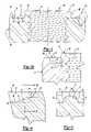
- FIG. 3is a side cross-sectional view of FIG. 2 in the direction of view arrows 3 — 3 ;
- FIG. 3Ais an enlarged cross-sectional view of the annular groove in the embodiment of the self-attaching nut shown in FIGS. 1 to 3 ;
- FIG. 4is an enlarged cross-sectional view of FIG. 3 in the area of view circle 4 ;
- FIG. 5is a partial cross-sectional view of FIG. 4 in the direction of view arrows 5 — 5 ;
- FIG. 6is a top perspective view of an alternative embodiment of the self-attaching nut of this invention.
- FIG. 7is a top view of the self-attaching nut shown in FIG. 6 ;
- FIG. 8is a partial side cross-sectional view of FIG. 7 in the direction of view arrows 8 — 8 ;
- FIG. 9is a partial cross-sectional view of FIG. 8 in the direction of view arrows 9 — 9 ;
- FIG. 10is a partial cross-sectional view of FIG. 8 in the direction of view arrows 10 — 10 ;
- FIG. 11is a top perspective view of a further alternative embodiment of the self-attaching nut of this invention.
- FIG. 12is a top view of the self-attaching nut shown in FIG. 11 ;
- FIG. 13is a partial side cross-sectional view of FIG. 12 in the direction of view arrows 13 — 13 ;
- FIG. 14is a partial cross-sectional view of FIG. 13 in the direction of view arrows 14 — 14 ;
- FIG. 15is a partial cross-sectional view of FIG. 13 in the direction of view arrows 15 — 15 ;
- FIG. 16is a top perspective view of a further alternative embodiment of the self-attaching nut of this invention.
- FIG. 17is a partial side cross-sectional view of FIG. 16 in the direction of view arrows 17 — 17 ;
- FIG. 18is a top perspective view of a further alternative embodiment of this invention.
- FIG. 19is a partial top view of the embodiment of the self-attaching nut shown in FIG. 18 ;
- FIG. 20is a partial cross-sectional view of FIG. 19 in the direction of view arrows 20 — 20 ;
- FIG. 21is a top perspective view of a further alternative embodiment of the self-attaching nut of this invention.
- FIG. 22is a partial top view of the self-attaching nut shown in FIG. 21 ;
- FIG. 23is a partial cross-sectional view of FIG. 22 in the direction of view arrows 23 — 23 ;
- FIG. 24is a partial cross-sectional view of FIG. 23 in the direction of view arrows 24 — 24 ;
- FIG. 25is a top perspective view of a further alternative embodiment of the self-attaching nut of this invention.
- FIG. 26is a partial top view of the self-attaching nut shown in FIG. 25 ;
- FIG. 27is a partial cross-sectional view of FIG. 26 in the direction of view arrows 27 — 27 .
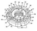
- FIGS. 1 to 5illustrate a first embodiment of the self-attaching nut 20 of this invention including a body portion 22 having an end face 24 (see FIG. 1 ), a central pilot portion 26 , an annular groove 28 surrounding the pilot portion 26 and an annular panel support face 30 surrounding the annular groove 28 .
- the pilot portion 26includes an annular preferably planar end face 32 and a bore 34 through the pilot portion.
- the end face 32is preferably above the plane of the annular panel support face 30 , as best shown in FIG.
- the annular groove 28includes an inner side wall 36 which, in the disclosed embodiment, is also the outer side wall of the pilot portion 26 , a bottom wall 38 and an outer side wall 40 .
- at least one of the inner and outer side walls 36 and 40is inclined toward the opposed side wall forming a restricted opening to the annular groove 28 .
- the outer side wall 40is inclined toward the pilot portion 26 or more specifically toward the inner side wall 36 and in the most preferred embodiment, the inner and outer side walls 36 and 40 are inclined toward each other as shown in FIG. 3A , forming a dovetail-shaped re-entrant groove providing improved push-off strength when the self-attaching nut is installed in a panel (not shown).
- the bore 34may be threaded as shown or the bore 34 may be cylindrical for receipt of a thread forming or thread rolling male fastener, such as a screw or bolt.
- the body portion 22may be polygonal as shown having a plurality of flat faces 42 or the outer surface of the self-attaching nut may also be cylindrical.
- the self-attaching nut of this inventionis generally conventional, although several of the prior art references do not include both an inner and outer inclined side wall 36 and 40 , respectively, which results in reduced push-off strength.
- the self-attaching nut of this inventionprovides improved integrity of the nut and panel assembly, including improved torque resistance and push-off strength.
- One important feature of the self-attaching nut shown in FIGS. 1 to 5is the circumferentially spaced radial notches 44 each having an outer wall 46 and opposed generally radial walls 48 .
- the radial walls 48may also be inclined inwardly toward each other from the outer wall 46 (not shown) to provide further torque resistance.
- the outer wall 48 of the radial notchesextends generally perpendicular to the panel planar support face 30 in the disclosed embodiment.
- the radial notches 44extend from the bottom wall 38 of the annular groove 28 to the top annular panel support face 30 .
- a panel(not shown) will be deformed into the radial notches 44 providing substantially improved torque resistance.
- the self-attaching nut 20includes eight radial notches 44 and the body portion includes eight flats 42 , wherein the radial notches 44 are defined in the corner portions 50 (see FIG. 1 ), providing maximum torque resistance.
- the embodiment of the self-attaching nut 20 illustrated in FIGS. 1 to 5further includes a plurality of radial ribs 52 .
- the radial ribs 52are integral with the inclined outer side wall 40 of the annular groove 28 .
- Each of the radial ribs 52include a top face 54 which is inclined from the outer side wall 40 of the annular groove 28 toward the bottom wall 38 .
- the radial inner ends 56 of the radial ribs 52merge with the bottom wall 38 as best shown in FIG.
- the top face 54 of the radial ribs 52is generally rectangular; however, the side faces 58 of the radial ribs are preferably angled outwardly as best shown in FIG. 5 .
- the outwardly inclined faces 58direct panel metal toward the bottom wall 38 of the annular groove 28 , improving filling of the annular groove 28 with panel metal during installation.
- the inclined top faces 54 of the radial ribs 52direct panel metal radially inwardly beneath the inclined inner side wall 36 as the panel metal is deformed against the radial ribs 52 , providing further improved torsion resistance and push-off strength.
- the self-attaching nut 20 illustrated in FIGS. 1 to 5may be utilized as a pierce nut, wherein the planar annular end face 32 of the central pilot portion 26 is driven against a panel (not shown) which is supported on a die button (not shown) and the pilot portion then pierces an opening in the panel which receives the pilot portion 26 therethrough.
- the die buttonwill include an annular lip configured to be received within the annular groove 28 which deforms the panel surrounding the panel opening into the annular groove 28 and against the bottom wall 38 and the top faces 54 of the radial ribs 52 .
- the inclined top face 54 of the radial ribsthen directs panel metal beneath the inclined inner side wall 36 , providing improved retention and the panel metal is further deformed around the inclined side faces 58 of the radial ribs and into the radial notches 44 providing further improved torque resistance.
- the inclined top face 54is spaced below the annular panel support face 30 and integral with the inclined outer side wall 40 at or above the midportion 60 (i.e., about one half the distance between the bottom wall 38 and the panel support face 30 ) of the inclined outer side wall 40 as shown in FIG. 4 , providing optimum torque resistance.
- the radial notches 44 in combination with the radial ribs 52provide superior torque resistance and further improve the push-off strength or integrity of the nut and panel installation.
- FIGS. 6 to 10illustrate a second embodiment of a self-attaching nut 120 of this invention, wherein the common elements of the self-attaching nut 120 are numbered the same as the elements of the self-attaching nut 20 described above except that the elements of the self-attaching nut 120 are numbered in the 100 series to simplify the description of the self-attaching nut 120 .
- the self-attaching nut 120 shown in FIGS. 5 to 10include a body portion 122 having an end face 124 , a central pilot portion 126 , an annular groove 128 surrounding the pilot portion and an annular panel support face 130 surrounding the annular groove 128 .
- the radial ribs 152are integral with the inclined outer side wall 140 , generally equally spaced between the radial notches 144 , as described above in regard to the self-attaching nut 20 shown in FIGS. 1 to 5 .
- the top face 154 of the radial ribsextends below the plane of the bottom wall 138 of the annular groove 128 , as best shown in FIG. 8 , wherein the radial inner end portion 156 of each of the radial ribs 152 is received in a radial channel 162 as shown in FIGS. 8 and 10 .
- the radial inner end 156 of the radial ribs 152is, however, spaced from the inner side wall 136 of the annular groove in that it is not integral with the outer wall of the pilot portion or the inclined inner wall 136 of the annular groove. All other features of the self-attaching nut 120 may be identical to the self-attaching nut 20 described above with regard to FIGS. 1 to 5 .
- the second embodiment of the self-attaching nut 120 shown in FIGS. 6 to 10has further advantages over the self-attaching nut 20 shown in FIGS. 1 to 5 .
- the panel metalwill be driven against the inclined top face 154 into the radial channels 162 in the bottom wall 138 of the annular groove 128 , providing further improved torque resistance.
- the panelwill be driven beneath the inclined inner side wall 136 by the inclined radial top face 154 which extends to adjacent the inclined inner side wall 136 , providing further improved push-off strength.
- the remaining features of the second embodiment of the self-attaching nut shown in FIGS. 6 to 10may be identical to the self-attaching nut 20 described in more detail above, and therefore no further description of the second embodiment is necessary for a full understanding of this embodiment.
- the third embodiment of the self-attaching nut 220 shown in FIGS. 11 to 15is essentially identical to the second embodiment shown in FIGS. 6 to 10 , except that the radial ribs 252 are integral with the inner side wall 236 of the annular groove 228 which, in the disclosed embodiment, is also the external surface of the central pilot portion 226 . That is, the self-attaching nut 220 includes a central pilot portion 226 , an annular groove 228 surrounding the pilot portion and an annular panel support face 230 surrounding the annular groove 228 .
- the self-attaching nut 220is identical to the self-attaching nut 120 described above and the elements of the self-attaching nut 220 are numbered the same as the elements of the self-attaching nut 120 except that the reference numbers of this third embodiment are numbered in the 200 series.
- panel metalis driven against the bottom wall 238 of the annular groove 228 and the outwardly inclined top faces 254 of the radial ribs 252 during installation of the self-attaching nut in a panel (not shown).
- the panel metalis thus driven beneath the inclined outer side wall 240 and into the radial channels 262 by the inclined top faces 254 , providing a very secure installation with improved torque resistance as described above with regard to the self-attaching nut 120 .
- the panel metalis simultaneously driven into the radial notches 244 in the outer side wall 240 .
- the fourth embodiment of the self-attaching nut 320 shown in FIGS. 16 and 17differs from the embodiment of the self-attaching nut 20 shown in FIGS. 1 to 5 in two material respects.
- the bottom wall 338 of the annular groove 328includes a plurality of alternating circumferentially spaced ribs 352 and 353 , including a first plurality of circumferentially spaced radial ribs 352 integral with the outer side wall of the annular groove 328 and a second plurality of radial ribs 353 integral with the inner side wall 336 of the annular groove 328 .
- the radial ends 356 of the radial ribs 352 and 353extend beyond a midportion 364 of the annular groove 328 , such that the alternating radial ribs 352 and 353 circumferentially “overlap.” That is, the radial inner ends 356 of the radial ribs 352 extend beyond the radial inner ends 356 of the radial ribs 353 in the bottom wall 338 of the annular groove 328 , such that the radial ribs 352 and 353 circumferentially overlap, as best shown in FIG. 16 . This alternately overlapping radial ribs 352 and 353 provide superior torque resistance.
- the top faces 354 of the radial ribs 352 and 353direct panel metal beneath both the inclined inner side wall 336 and the inclined outer side wall 340 providing improved push-off strength.
- the second difference of the self-attaching nut 320 shown in FIGS. 16 and 17is that the radial ribs 352 are integral with the outer wall 346 of the radial notches 344 , but have a circumferential width less than the circumferential width of the radial notches measured between the opposed radial walls 348 .
- the side faces 358 of the radial ribs 352 and 353are inclined outwardly from the top face 354 which, during installation of the self-attaching nut 320 in a panel (not shown), directs panel metal between the radial ribs 352 and the opposed radial walls 348 .
- the radial outer end of the radial notches 352is spaced below the plane of the annular panel support face 330 at or above a midportion of the outer walls 346 , such that the panel metal will fill the upper portion of the radial notches 344 .
- the self-attaching nut 320 shown in FIGS. 16 and 17provide further advantages over the self-attaching nuts previously described.
- First, the alternating overlapping radial ribs 352 and 353provide superior torque resistance over the previously described embodiments.
- Finally, forming the radial ribs 352 integral with the outer wall 346 of the radial notches 344locates the radial ribs further from the axis of the bore 334 , providing further torque resistance.
- the self-attaching nut 320 shown in FIGS. 16 and 17may otherwise be identical to the self-attaching nut 20 described above with regard to FIGS. 1 to 5 and have been numbered the same, except that the elements are numbered in the 300 series and therefore no further description is required for a complete understanding of this embodiment of the self-attaching nut of this invention.
- the fifth embodiment of the self-attaching nut 420 of this invention shown in FIGS. 18 to 20differs from the embodiment of the self-attaching nut 20 shown in FIGS. 1 to 5 in two material respects.
- the radial ribsare integral with either the inner or outer side walls of the annular groove, but spaced from the opposed wall, particularly where the radial ribs are integral with the outer side wall as described above with regard to the embodiments of the self-attaching nuts 20 , 120 , 220 and 320 described above.
- the radial ribs 152extend below the plane of the bottom wall 138 and are therefore not integral with the outer side wall of the pilot portion 126 , further reducing the likelihood of thread distortion.
- the radial ribs 452extend to adjacent the inner side wall 436 of the annular groove 428 above the plane of the bottom wall 438 as best shown in FIG. 20 .
- the radial ribs 452further include circumferential channels 464 having opposed faces 466 which, in the disclosed embodiment, extend to the bottom wall 438 of the annular groove 428 as best shown in FIG. 20 .
- this embodiment of the self-attaching nut 420may provide further torque resistance because of the increased area of the side faces 458 of the radial ribs 452 .
- the remaining features or elements of the self-attaching nut 420 shown in FIGS. 18 to 20may be identical to the embodiment of the self-attaching nut 20 shown in FIGS. 1 to 5 and have therefore been numbered the same as the self-attaching nut 20 except that the self-attaching nut 420 is numbered in the 400 series. Therefore, no further description of the embodiment of the self-attaching nut 420 is necessary for a complete understanding of this embodiment.
- the sixth embodiment of the self-attaching nut 520 shown in FIGS. 21 to 24differs from the embodiments of the self-attaching nuts previously described in that a plurality of the circumferentially spaced radial notches 544 include a pair of circumferentially spaced radial ribs 552 and 553 integral with the outer wall 546 and one of the opposed radial walls 548 of the radial notches 544 , as shown.
- the radial ribs 552 and 553each include a top face 554 which may extend to the panel support face 530 as shown in FIGS. 23 and 24 or spaced below the panel support face 530 as described above with the previous embodiments.
- the radial ribs 552 and 553further include opposed outwardly inclined faces 568 and opposed inwardly inclined faces 570 , wherein the inwardly inclined faces 570 form an undercut as shown in FIG. 24 .
- the panel metalis deformed against the opposed outwardly inclined faces 568 and beneath the opposed inwardly inclined faces 570 against the bottom wall 538 of the annular groove.
- the radial inner ends 556 of the radial ribs 552 and 554are spaced above the plane of the bottom wall 538 of the annular groove 528 and include an inwardly inclined end face 572 as shown in FIG. 23 . As shown in FIGS.
- the radial ribs 552 and 553are located in alternative radial notches 544 . That is, four of the radial notches 544 include a pair of radial ribs 552 and 553 and the remaining four radial notches are clear or open as described above with regard to FIG. 1 .
- a die member (not shown) utilized to install the self-attaching nut 520will include an annular lip portion as utilized for installing self-attaching nuts of this type and shown in the above-referenced patents.
- the annular lipmay further include radial portions for receipt between each pair of radial ribs 552 and 553 .
- the self-attaching nut 520may be identical to the self-attaching nuts previously described and the reference numbers are identical to the previously described self-attaching nuts, except that the reference numbers are in the 500 series. That is, the self-attaching nut 520 includes a central pilot portion 526 having a bore 534 therethrough, an annular groove 528 surrounding the pilot portion 526 and an annular panel support face 530 surrounding the annular groove 528 .
- each of the radial notches 644includes only one radial rib 652 integral with the outer wall 646 of the radial notches 644 , generally equally spaced between the radial walls 648 . That is, in the embodiment of the self-attaching nut 620 shown in FIGS.
- each of the radial notches 644includes a radial rib 652 integral with the outer wall 646 of the radial notches having a circumferential width less than the circumferential width of the radial notches 644 measured between the opposed radial walls 648 , wherein the radial ribs 652 extend to the panel support face 630 as shown in FIG. 27 and the radial inner ends 656 of the radial ribs 652 is spaced above the plane of the bottom wall 638 of the annular groove 628 and the radial ribs 652 each include inwardly inclined end faces 672 as shown in FIG. 27 .
- the radial ribs 652may also have a width equal to the width of the notches 644 .
- the self-attaching nut 620may be identical to the embodiment of the self-attaching nut 520 and the previously described embodiments and therefore the self-attaching nut 620 is numbered the same, except that the reference numbers are in the 600 series.
- panel metalis deformed against the bottom wall 638 and the inwardly inclined top faces 654 of the radial ribs 652 .
- the top faces 654 of the radial ribs 652then deform the panel metal radially inwardly beneath the inclined inner side wall 636 and beneath the inwardly inclined end faces 672 providing improved push-off strength.
- the panel metalis further deformed circumferentially against the inclined side faces 658 into the radial notches 644 and against the side faces 658 to the bottom wall 638 of the annular groove 628 . Because the side faces 658 of the radial ribs 652 have a greater surface area, the radial ribs 652 provide greater torque resistance than where the radial ribs extend to a midportion of the outer wall.
- the improvements in torque resistance and push-off strength provided by the various embodiments of the self-attaching nuts disclosed hereinmay be utilized individually or in combination to provide improved torque resistance and push-off strength.
- the radial ribsare integral with either the inner or outer side walls of the annular groove and the radial inner ends of the radial ribs are preferably spaced from the opposed side wall.
- the radial ribsare integral with the outer wall of the annular groove, but may be integral with either the inclined outer side wall of the annular groove or the outer wall of the radial notches which, in a preferred embodiment, extends generally perpendicular to the panel support face surrounding the annular pilot.
- the outer wall of the radial notcheswhen utilized, forms the outer side wall of the annular groove and thus, as used herein, reference to the radial notches as integral with the outer side wall includes radial notches integral with the outer wall of the radial notches.
- the outer side wall of the annular grooveis inclined toward the pilot portion and the inner side wall of the annular groove is inclined toward the outer side wall, forming a dovetail-shaped annular groove providing improved push-off strength.
- the bottom wall of the annular grooveextends generally perpendicular to the axis of the bore through the pilot portion.
- the bottom wallmay also be inclined toward either the inner or outer side wall of the annular groove.
- the bottom wallmust be inclined toward either the inner or outer side wall of the annular groove a few degrees to permit removal of the self-attaching nut from a die member used to form the annular groove. This would be true of any self-attaching nut of this type.
- the embodiments of the self-attaching nuts described abovemay be utilized as either a pierce or clinch nut.
- the metal panelis supported in a die press on a die member or die button.
- the die buttonincludes an annular clinching lip configured to be received in the annular groove generally having outwardly tapered surfaces as is known in this art.
- the die buttonis located in the lower die shoe of a die press and the self-attaching nut is received in an installation head located in the upper die shoe having a reciprocating plunger which drives the self-attaching nut against the panel.
- the self-attaching nutis utilized as a pierce nut
- the end face of the pilot portionpierces or punches an opening in the panel and the annular lip of the die button deforms the panel metal into the annular groove and against the bottom wall of the groove as is known in this art.
- the self-attaching nutis utilized as a clinch nut
- an openingis preformed in the panel configured to receive the pilot portion therethrough and the annular lip of the die member then deforms the panel metal into the re-entrant groove and against the bottom wall in the same manner as described.
- the radial ribsare generally equally circumferentially spaced and integral with either the inner or outer side walls of the annular groove and spaced from the opposed side wall to reduce deformation of the thread cylinder of the bore through the pilot portion.
- the boremay be unthreaded to receive a self-tapping or thread rolling male fastener.
- the annular grooveincludes an inner wall inclined toward the outer wall of the annular groove and an outer wall inclined toward the pilot portion and the outer wall includes radial ribs integral with the outer wall of the annular groove, either integral with the inclined outer side wall or the outer wall of the radial notches.
- the outer wall of the radial notchesmay be perpendicular to the panel support face, as disclosed in the embodiments illustrated in the drawings, or the outer wall of the radial notches may be inclined, preferably toward the pilot portion.
- the radial ribsmay be integral with the inner wall of the annular groove or the pilot portion or more preferably the self-attaching nut may include alternating circumferentially spaced radial ribs integral with the pilot portion and the outer wall of the annular groove as shown, for example, in FIGS. 16 and 17 .
- the bottom wall of the annular grooveis generally perpendicular to the axis of the bore through the pilot portion or parallel to the panel support face.
- the bottom wallmay also be angled inwardly toward the pilot portion. As will be understood by those skilled in this art, however, the bottom wall will generally be inclined toward the pilot portion about one to three degrees to permit removal of the self-attaching nut from the die member of the cold header following formation of the self-attaching nut of this invention.
- the radial ribsare integral with either the inner or outer side walls of the annular groove at or above a midportion of the side wall.
Landscapes
- Engineering & Computer Science (AREA)
- Chemical & Material Sciences (AREA)
- Mechanical Engineering (AREA)
- General Engineering & Computer Science (AREA)
- Combustion & Propulsion (AREA)
- Chemical Kinetics & Catalysis (AREA)
- Automatic Assembly (AREA)
- Forging (AREA)
- Connection Of Plates (AREA)
Abstract
Description
Claims (21)
Priority Applications (1)
| Application Number | Priority Date | Filing Date | Title |
|---|---|---|---|
| US11/089,891US7112024B2 (en) | 2002-08-30 | 2005-03-25 | Self-attaching nut |
Applications Claiming Priority (3)
| Application Number | Priority Date | Filing Date | Title |
|---|---|---|---|
| US10/232,335US6851904B2 (en) | 2002-08-30 | 2002-08-30 | Self-attaching female fastener and method of installation |
| US10/439,526US6994500B2 (en) | 2002-08-30 | 2003-05-16 | Self-attaching nut |
| US11/089,891US7112024B2 (en) | 2002-08-30 | 2005-03-25 | Self-attaching nut |
Related Parent Applications (1)
| Application Number | Title | Priority Date | Filing Date |
|---|---|---|---|
| US10/439,562DivisionUS6862927B2 (en) | 2003-05-16 | 2003-05-16 | Filters for engine exhaust particulates |
Publications (2)
| Publication Number | Publication Date |
|---|---|
| US20050163590A1 US20050163590A1 (en) | 2005-07-28 |
| US7112024B2true US7112024B2 (en) | 2006-09-26 |
Family
ID=55235759
Family Applications (6)
| Application Number | Title | Priority Date | Filing Date |
|---|---|---|---|
| US11/089,891Expired - LifetimeUS7112024B2 (en) | 2002-08-30 | 2005-03-25 | Self-attaching nut |
| US11/189,685Expired - LifetimeUS7258518B2 (en) | 2002-08-30 | 2005-07-26 | Self-attaching nut |
| US11/713,420AbandonedUS20070154282A1 (en) | 2002-08-30 | 2007-03-02 | Self-attaching nut |
| US11/713,174Expired - LifetimeUS7597515B2 (en) | 2002-08-30 | 2007-03-02 | Self-attaching nut |
| US11/713,175AbandonedUS20070154280A1 (en) | 2002-08-30 | 2007-03-02 | Self-attaching nut |
| US11/713,313Expired - LifetimeUS7419344B2 (en) | 2002-08-30 | 2007-03-02 | Self-attaching nut |
Family Applications After (5)
| Application Number | Title | Priority Date | Filing Date |
|---|---|---|---|
| US11/189,685Expired - LifetimeUS7258518B2 (en) | 2002-08-30 | 2005-07-26 | Self-attaching nut |
| US11/713,420AbandonedUS20070154282A1 (en) | 2002-08-30 | 2007-03-02 | Self-attaching nut |
| US11/713,174Expired - LifetimeUS7597515B2 (en) | 2002-08-30 | 2007-03-02 | Self-attaching nut |
| US11/713,175AbandonedUS20070154280A1 (en) | 2002-08-30 | 2007-03-02 | Self-attaching nut |
| US11/713,313Expired - LifetimeUS7419344B2 (en) | 2002-08-30 | 2007-03-02 | Self-attaching nut |
Country Status (1)
| Country | Link |
|---|---|
| US (6) | US7112024B2 (en) |
Cited By (14)
| Publication number | Priority date | Publication date | Assignee | Title |
|---|---|---|---|---|
| US20060002781A1 (en)* | 2004-06-21 | 2006-01-05 | Robert Mangapora | Captive fastener |
| US20070154282A1 (en)* | 2002-08-30 | 2007-07-05 | Ward Richard P | Self-attaching nut |
| US20070151091A1 (en)* | 2006-01-05 | 2007-07-05 | Profil Verbindungstechnik Gmbh & Co. Kg | Functional element, a component assembly consisting of a functional element and a sheet metal part and also a method for the attachment of the functional element to a sheet metal part |
| US20070231105A1 (en)* | 2002-08-30 | 2007-10-04 | Parker John M | Heavy metal pierce nut |
| US20070297870A1 (en)* | 2007-08-24 | 2007-12-27 | Vrana John J | Self-attaching female fastener |
| US20080232923A1 (en)* | 2002-08-30 | 2008-09-25 | Whitesell International Corporation | Self-attaching nut |
| WO2008124804A1 (en)* | 2007-04-10 | 2008-10-16 | Whitesell International Corporation | Self-attaching nut |
| US20100143065A1 (en)* | 2008-12-05 | 2010-06-10 | Zink Frederick E | Fastener with anti-rotation clip |
| US20100209210A1 (en)* | 2007-08-24 | 2010-08-19 | Zdravko Kovac | Self-attaching nut |
| US20190010973A1 (en)* | 2016-03-14 | 2019-01-10 | Richard Bergner Verbindungstechnik Gmbh & Co. Kg | Self-punching press-fit element, press-fit connection, and method for producing such a press-fit connection |
| US20210115961A1 (en)* | 2018-07-27 | 2021-04-22 | Aoyama Seisakusho Co., Ltd. | Nut and fixing structure of nut |
| US20220381286A1 (en)* | 2021-05-27 | 2022-12-01 | Rb&W Manufacturing Llc | Self-clinching and self-piercing construction element with multi-purpose pilot |
| US20230102242A1 (en)* | 2020-02-21 | 2023-03-30 | Ramco Specialties, Inc. | Pierce nut |
| USD1051710S1 (en)* | 2022-07-13 | 2024-11-19 | Wei In Enterprise Co., Ltd. | Rivet nut |
Families Citing this family (18)
| Publication number | Priority date | Publication date | Assignee | Title |
|---|---|---|---|---|
| US20040146375A1 (en)* | 2002-08-30 | 2004-07-29 | Ward Richard P. | Self-attaching nut |
| USD557132S1 (en)* | 2006-06-05 | 2007-12-11 | Shinjo Manufacturing Co., Ltd. | Self-piercing nut |
| DE102008032696A1 (en)* | 2008-07-03 | 2010-01-07 | Arnold & Shinjo Gmbh & Co. Kg | fastener |
| USD613596S1 (en)* | 2009-04-16 | 2010-04-13 | Bas Components Limited | Screw nut |
| EP2662052B1 (en)* | 2009-08-26 | 2015-07-08 | Straumann Holding AG | Dental implant and kit including said dental implant |
| DE102009039817A1 (en)* | 2009-09-02 | 2011-03-03 | Profil Verbindungstechnik Gmbh & Co. Kg | Self-piercing nut member and assembly part consisting of the nut member and a sheet metal part |
| DE102010032866A1 (en)* | 2010-07-30 | 2012-02-02 | Profil Verbindungstechnik Gmbh & Co. Kg | Self-piercing nut member and assembly part consisting of the nut member and a sheet metal part |
| CA2861540C (en) | 2011-01-17 | 2016-10-04 | Thomas M. Espinosa | Checker nut for locking a threaded body to a threaded rod and concrete reinforcement assembly |
| DE102011108224A1 (en)* | 2011-07-21 | 2013-01-24 | Profil Verbindungstechnik Gmbh & Co. Kg | Functional element with anti-rotation features and assembly component consisting of the functional element and a sheet metal part |
| EP2644911A3 (en) | 2012-03-27 | 2016-08-17 | Profil Verbindungstechnik GmbH & Co. KG | Function element in the form of a press element |
| USD696578S1 (en)* | 2012-10-25 | 2013-12-31 | Topre Corporation | Self-piercing clinch nut |
| USD696577S1 (en)* | 2012-10-25 | 2013-12-31 | Topre Corporation | Self-piercing clinch nut |
| USD871201S1 (en)* | 2018-05-28 | 2019-12-31 | Shinjo Holdings Co., Ltd. | Self-piercing clinch nut |
| USD914492S1 (en)* | 2019-05-30 | 2021-03-30 | Curiteva, Inc. | Resilient fastener washer |
| CN111350744A (en)* | 2020-03-10 | 2020-06-30 | 嘉兴萨雷特汽车零部件有限公司 | Combined type check bolt for automobile |
| DE102020111696A1 (en)* | 2020-04-29 | 2021-11-04 | Profil Verbindungstechnik Gmbh & Co. Kg | Functional element |
| USD1015864S1 (en)* | 2022-03-31 | 2024-02-27 | Fluidmaster, Inc. | Nut |
| USD1014235S1 (en)* | 2022-03-31 | 2024-02-13 | Fluidmaster, Inc. | Washer |
Citations (37)
| Publication number | Priority date | Publication date | Assignee | Title |
|---|---|---|---|---|
| US1919552A (en) | 1930-06-26 | 1933-07-25 | Smith Corp A O | Attaching grommets to metal plates |
| US3213914A (en) | 1961-11-06 | 1965-10-26 | Illinois Tool Works | Self-piercing nut with attaching groove |
| US3253631A (en) | 1963-06-17 | 1966-05-31 | Republic Steel Corp | Cold-formed self-piercing nut |
| US3282315A (en) | 1964-07-09 | 1966-11-01 | Zahodiakin Tania | Nut mechanically fused in place |
| US3736969A (en) | 1966-09-22 | 1973-06-05 | H Warn | Pierce nut |
| US3810291A (en) | 1969-07-11 | 1974-05-14 | Multifastener Corp | Installation die and nut and method of installing a nut in a panel |
| US3910331A (en) | 1974-08-12 | 1975-10-07 | Kaynar Mfg Co | Nut |
| US4389766A (en) | 1980-06-06 | 1983-06-28 | The Lamson & Sessions Co. | Method of mounting a fastener |
| US4432681A (en) | 1981-05-28 | 1984-02-21 | Russell Burdsall & Ward Corporation | Fastener |
| US4486133A (en)* | 1981-11-23 | 1984-12-04 | Midland-Ross Corporation | Retainer for mechanical fastener member |
| US4543023A (en) | 1981-05-28 | 1985-09-24 | Russell, Burdsall & Ward Corporation | Fastener |
| US4627776A (en) | 1985-05-14 | 1986-12-09 | Russell, Burdsall & Ward Corporation | Fastener |
| US4637766A (en) | 1985-06-17 | 1987-01-20 | Textron Inc. | Clinch type fastener |
| US4708556A (en) | 1985-05-14 | 1987-11-24 | Russell, Burdsall & Ward Corporation | Fastener attached to sheet metal |
| US4810143A (en) | 1983-12-21 | 1989-03-07 | Multifastener Corporation | Fastener and panel assembly |
| US4893976A (en) | 1988-03-01 | 1990-01-16 | Textron Inc. | Clinch type fastening structure |
| US4911592A (en) | 1980-02-02 | 1990-03-27 | Multifastener Corporation | Method of installation and installation apparatus |
| US5244326A (en) | 1992-05-19 | 1993-09-14 | Arne Henriksen | Closed end ridged neck threaded fastener |
| EP0561715A1 (en) | 1992-03-20 | 1993-09-22 | Former | Self-setting and self-piercing nut and screw |
| US5251370A (en) | 1991-10-31 | 1993-10-12 | Profil Verbindungstechnik Gmbh & Co. | Method of attaching a fastening element to a panel |
| US5302066A (en) | 1993-01-19 | 1994-04-12 | Textron Inc. | Locking fastener |
| US5340251A (en) | 1992-01-31 | 1994-08-23 | Multifastener Corporation | Self-attaching fastener and installation die |
| US5423645A (en) | 1993-08-04 | 1995-06-13 | Profil Verbindungstechnik Gmbh & Co. Kg | Fastener and panel assembly |
| US5509766A (en) | 1993-01-11 | 1996-04-23 | Nass Magnet Gmbh | Fastening apparatus |
| US5531552A (en) | 1984-08-03 | 1996-07-02 | Multifastener Corporation | Self-attaching nut and method of making same |
| US5549430A (en) | 1992-01-31 | 1996-08-27 | Multifastener Corporation | Self-attaching fastener and installation die |
| US5613815A (en) | 1991-10-31 | 1997-03-25 | Profil - Verbindungstechnik | Fastener and panel assembly and method of making same |
| US5782594A (en) | 1996-08-16 | 1998-07-21 | Profil-Verbindungstechnik Gmbh & Co Kg | Self-attaching fastener & method |
| US5882159A (en) | 1996-08-16 | 1999-03-16 | Profil Verbindungstechnik, Gmbh & Co. | Element, method of attaching the element to a plate-like component, component assembly and die button |
| US6004087A (en) | 1995-08-18 | 1999-12-21 | Profil-Verbindungstechnik Gmbh & Co. Kg | Self-attaching fastener |
| US6220804B1 (en) | 1999-03-24 | 2001-04-24 | R B & W Corporation | Self-piercing clinch nut |
| US6257814B1 (en) | 1995-08-18 | 2001-07-10 | Profil Verbindungstechnik & Co. | Self-attaching fastener, method of forming same and method of attachment |
| USD457054S1 (en) | 1999-03-24 | 2002-05-14 | R B & W Corporation | Self-piercing clinch nut |
| US20020159858A1 (en) | 2000-05-19 | 2002-10-31 | Hidenori Ikami | Pierce nut |
| US20020172573A1 (en) | 1999-03-24 | 2002-11-21 | Pamer W. Richard | Self-piercing clinch nut |
| US20020182032A1 (en) | 2001-05-31 | 2002-12-05 | Anderson Jeffrey D. | Integral washer and threaded fastener assembly and method for making same |
| US6543979B2 (en) | 2000-04-18 | 2003-04-08 | Honda Giken Kogyo Kabushiki Kaisha | Clinch nut assembly and method of producing clinch nut |
Family Cites Families (33)
| Publication number | Priority date | Publication date | Assignee | Title |
|---|---|---|---|---|
| US172573A (en)* | 1876-01-25 | Improvement in ticket-reels | ||
| US100789A (en)* | 1870-03-15 | Improved sofa bsd | ||
| US182032A (en)* | 1876-09-12 | Improvement in piano attachments | ||
| US159858A (en)* | 1875-02-16 | Improvement in pegging-machines | ||
| US535411A (en)* | 1895-03-12 | Furnace | ||
| US1332686A (en)* | 1919-01-16 | 1920-03-02 | Henry S Reynolds | Sput for metallic receptacles |
| US2037586A (en)* | 1934-06-27 | 1936-04-14 | Illinois Tool Works | Locking means for threaded elements |
| US2037286A (en) | 1935-06-05 | 1936-04-14 | Delta Mfg Co | Jointer fence adjustment |
| US2147211A (en) | 1936-05-29 | 1939-02-14 | Illinois Tool Works | Fastening device |
| US2128757A (en) | 1936-05-29 | 1938-08-30 | Illinois Tool Works | Means for fastening |
| US3000420A (en) | 1958-03-14 | 1961-09-19 | Spokes Albert | Nut with recesses to receive metal of the workpiece |
| GB1050351A (en)* | 1959-05-06 | |||
| US3133579A (en)* | 1960-11-10 | 1964-05-19 | Kaynar Mfg Co | Self-staking fastener having alternate teeth and lands |
| US3234987A (en)* | 1962-05-18 | 1966-02-15 | Stanley Works | Self-piercing nut with attaching flange |
| US3282317A (en) | 1964-06-02 | 1966-11-01 | Zahodiakin Tania | Receptacle mechanically fused in place |
| US3358727A (en)* | 1965-02-26 | 1967-12-19 | United Carr Inc | Counterboring flanged nut |
| US3878599A (en) | 1969-07-11 | 1975-04-22 | Multifastener Corp | Method of forming a nut and panel assembly |
| US3640326A (en)* | 1969-10-17 | 1972-02-08 | Armco Steel Corp | Bolt |
| US4018257A (en)* | 1975-12-15 | 1977-04-19 | Cold Fasteners, Inc. | Self-flanging nut and joint construction |
| US5207588A (en) | 1980-02-02 | 1993-05-04 | Multifastener Corporation | Electrical grounding stud |
| US4831698A (en) | 1983-03-28 | 1989-05-23 | Multifastener Corporation | Method of attaching a female element to a panel |
| JPS58109710A (en) | 1981-12-24 | 1983-06-30 | 有限会社新城製作所 | Piercing nut |
| US6125524A (en)* | 1994-03-25 | 2000-10-03 | Multifastener Corporation | Rivetable element, assembly, method of assembly and riveting die |
| DE29508852U1 (en)* | 1995-05-29 | 1996-09-26 | EJOT Verbindungstechnik GmbH & Co. KG, 57334 Bad Laasphe | Countersunk screw |
| DE19710246A1 (en) | 1997-03-12 | 1998-09-17 | Profil Verbindungstechnik Gmbh | Element and method for inserting the element into a plate-shaped component |
| US6108893A (en)* | 1997-04-23 | 2000-08-29 | Fabristeel Products Inc. | Fastener, die button and method of installing a fastener into a panel |
| US6318940B1 (en) | 2000-06-21 | 2001-11-20 | Illinois Tool Works Inc. | Fastener for self-locking securement within a panel opening |
| DE20113853U1 (en)* | 2001-08-22 | 2001-11-15 | Textron Verbindungstechnik GmbH & Co. oHG, 56567 Neuwied | Self-piercing, twist and squeeze-proof fastening element that can be pressed into a sheet |
| US7112024B2 (en)* | 2002-08-30 | 2006-09-26 | Whitesell International Corporation | Self-attaching nut |
| US6851904B2 (en)* | 2002-08-30 | 2005-02-08 | Fabristeel Products, Inc. | Self-attaching female fastener and method of installation |
| US7066700B2 (en)* | 2002-08-30 | 2006-06-27 | Whitesell International Corporation | Self-attaching fastener and method of attachment |
| US20040146375A1 (en)* | 2002-08-30 | 2004-07-29 | Ward Richard P. | Self-attaching nut |
| US20040042871A1 (en)* | 2002-09-04 | 2004-03-04 | Wojciechowski Stanley E. | Self-attaching female fastener element, sealed fastener and panel assembly and method of forming same |
- 2005
- 2005-03-25USUS11/089,891patent/US7112024B2/ennot_activeExpired - Lifetime
- 2005-07-26USUS11/189,685patent/US7258518B2/ennot_activeExpired - Lifetime
- 2007
- 2007-03-02USUS11/713,420patent/US20070154282A1/ennot_activeAbandoned
- 2007-03-02USUS11/713,174patent/US7597515B2/ennot_activeExpired - Lifetime
- 2007-03-02USUS11/713,175patent/US20070154280A1/ennot_activeAbandoned
- 2007-03-02USUS11/713,313patent/US7419344B2/ennot_activeExpired - Lifetime
Patent Citations (42)
| Publication number | Priority date | Publication date | Assignee | Title |
|---|---|---|---|---|
| US1919552A (en) | 1930-06-26 | 1933-07-25 | Smith Corp A O | Attaching grommets to metal plates |
| US3213914A (en) | 1961-11-06 | 1965-10-26 | Illinois Tool Works | Self-piercing nut with attaching groove |
| US3253631A (en) | 1963-06-17 | 1966-05-31 | Republic Steel Corp | Cold-formed self-piercing nut |
| US3282315A (en) | 1964-07-09 | 1966-11-01 | Zahodiakin Tania | Nut mechanically fused in place |
| US3736969A (en) | 1966-09-22 | 1973-06-05 | H Warn | Pierce nut |
| US3810291A (en) | 1969-07-11 | 1974-05-14 | Multifastener Corp | Installation die and nut and method of installing a nut in a panel |
| US3910331A (en) | 1974-08-12 | 1975-10-07 | Kaynar Mfg Co | Nut |
| US4911592A (en) | 1980-02-02 | 1990-03-27 | Multifastener Corporation | Method of installation and installation apparatus |
| US4389766A (en) | 1980-06-06 | 1983-06-28 | The Lamson & Sessions Co. | Method of mounting a fastener |
| US4432681A (en) | 1981-05-28 | 1984-02-21 | Russell Burdsall & Ward Corporation | Fastener |
| US4543023A (en) | 1981-05-28 | 1985-09-24 | Russell, Burdsall & Ward Corporation | Fastener |
| US4486133A (en)* | 1981-11-23 | 1984-12-04 | Midland-Ross Corporation | Retainer for mechanical fastener member |
| US4810143A (en) | 1983-12-21 | 1989-03-07 | Multifastener Corporation | Fastener and panel assembly |
| US5531552A (en) | 1984-08-03 | 1996-07-02 | Multifastener Corporation | Self-attaching nut and method of making same |
| US4627776A (en) | 1985-05-14 | 1986-12-09 | Russell, Burdsall & Ward Corporation | Fastener |
| US4708556A (en) | 1985-05-14 | 1987-11-24 | Russell, Burdsall & Ward Corporation | Fastener attached to sheet metal |
| US4637766A (en) | 1985-06-17 | 1987-01-20 | Textron Inc. | Clinch type fastener |
| US4893976A (en) | 1988-03-01 | 1990-01-16 | Textron Inc. | Clinch type fastening structure |
| US5251370A (en) | 1991-10-31 | 1993-10-12 | Profil Verbindungstechnik Gmbh & Co. | Method of attaching a fastening element to a panel |
| US5335411A (en) | 1991-10-31 | 1994-08-09 | Profil Verbindungstechnik Gmbh & Co. Kg | Method of attaching a fastening element to a panel |
| US5613815A (en) | 1991-10-31 | 1997-03-25 | Profil - Verbindungstechnik | Fastener and panel assembly and method of making same |
| US5340251A (en) | 1992-01-31 | 1994-08-23 | Multifastener Corporation | Self-attaching fastener and installation die |
| US5549430A (en) | 1992-01-31 | 1996-08-27 | Multifastener Corporation | Self-attaching fastener and installation die |
| EP0561715A1 (en) | 1992-03-20 | 1993-09-22 | Former | Self-setting and self-piercing nut and screw |
| US5244326A (en) | 1992-05-19 | 1993-09-14 | Arne Henriksen | Closed end ridged neck threaded fastener |
| US5509766A (en) | 1993-01-11 | 1996-04-23 | Nass Magnet Gmbh | Fastening apparatus |
| US5302066A (en) | 1993-01-19 | 1994-04-12 | Textron Inc. | Locking fastener |
| US5423645A (en) | 1993-08-04 | 1995-06-13 | Profil Verbindungstechnik Gmbh & Co. Kg | Fastener and panel assembly |
| US6257814B1 (en) | 1995-08-18 | 2001-07-10 | Profil Verbindungstechnik & Co. | Self-attaching fastener, method of forming same and method of attachment |
| US6004087A (en) | 1995-08-18 | 1999-12-21 | Profil-Verbindungstechnik Gmbh & Co. Kg | Self-attaching fastener |
| US6081994A (en) | 1995-08-18 | 2000-07-04 | Profil Verbindungstechnik Gmbh & Co. | Element, method of attaching the element to a plate-like component, component assembly and die button |
| US6276040B1 (en) | 1996-08-16 | 2001-08-21 | Profil Verbindungstechnik, Gmbh | Element, method of attaching the element to a plate-like component, component assembly and die buttons |
| US5882159A (en) | 1996-08-16 | 1999-03-16 | Profil Verbindungstechnik, Gmbh & Co. | Element, method of attaching the element to a plate-like component, component assembly and die button |
| US5782594A (en) | 1996-08-16 | 1998-07-21 | Profil-Verbindungstechnik Gmbh & Co Kg | Self-attaching fastener & method |
| US6220804B1 (en) | 1999-03-24 | 2001-04-24 | R B & W Corporation | Self-piercing clinch nut |
| US20010010789A1 (en) | 1999-03-24 | 2001-08-02 | Pamer W. Richard | Self-piercing clinch nut |
| USD457054S1 (en) | 1999-03-24 | 2002-05-14 | R B & W Corporation | Self-piercing clinch nut |
| US6409444B2 (en) | 1999-03-24 | 2002-06-25 | R B & W Corporation | Self-piercing clinch nut |
| US20020172573A1 (en) | 1999-03-24 | 2002-11-21 | Pamer W. Richard | Self-piercing clinch nut |
| US6543979B2 (en) | 2000-04-18 | 2003-04-08 | Honda Giken Kogyo Kabushiki Kaisha | Clinch nut assembly and method of producing clinch nut |
| US20020159858A1 (en) | 2000-05-19 | 2002-10-31 | Hidenori Ikami | Pierce nut |
| US20020182032A1 (en) | 2001-05-31 | 2002-12-05 | Anderson Jeffrey D. | Integral washer and threaded fastener assembly and method for making same |
Non-Patent Citations (2)
| Title |
|---|
| RIMS Brochure (English). |
| RIMS Brochure (German). |
Cited By (25)
| Publication number | Priority date | Publication date | Assignee | Title |
|---|---|---|---|---|
| US20070154282A1 (en)* | 2002-08-30 | 2007-07-05 | Ward Richard P | Self-attaching nut |
| US20070154281A1 (en)* | 2002-08-30 | 2007-07-05 | Ward Richard P | Self-attaching nut |
| US20070231105A1 (en)* | 2002-08-30 | 2007-10-04 | Parker John M | Heavy metal pierce nut |
| US7419344B2 (en)* | 2002-08-30 | 2008-09-02 | Whitesell International Corporation | Self-attaching nut |
| US20080232923A1 (en)* | 2002-08-30 | 2008-09-25 | Whitesell International Corporation | Self-attaching nut |
| US7591623B2 (en) | 2002-08-30 | 2009-09-22 | Whitesell International Corporation | Heavy metal pierce nut |
| US7597515B2 (en) | 2002-08-30 | 2009-10-06 | Whitesell International Corporation | Self-attaching nut |
| US20060002781A1 (en)* | 2004-06-21 | 2006-01-05 | Robert Mangapora | Captive fastener |
| US20070151091A1 (en)* | 2006-01-05 | 2007-07-05 | Profil Verbindungstechnik Gmbh & Co. Kg | Functional element, a component assembly consisting of a functional element and a sheet metal part and also a method for the attachment of the functional element to a sheet metal part |
| US8328485B2 (en)* | 2006-01-05 | 2012-12-11 | Profil Verbindungstechnik Gmbh & Co., Kg | Functional element, a component assembly consisting of a functional element and a sheet metal part and also a method for the attachment of the functional element to a sheet metal part |
| WO2008124804A1 (en)* | 2007-04-10 | 2008-10-16 | Whitesell International Corporation | Self-attaching nut |
| US20100209210A1 (en)* | 2007-08-24 | 2010-08-19 | Zdravko Kovac | Self-attaching nut |
| US8142125B2 (en) | 2007-08-24 | 2012-03-27 | Whitesell International Corporation | Self-attaching female fastener |
| US20070297870A1 (en)* | 2007-08-24 | 2007-12-27 | Vrana John J | Self-attaching female fastener |
| US8608420B2 (en) | 2007-08-24 | 2013-12-17 | Whitesell International Corporation | Self-attaching nut |
| US20100143065A1 (en)* | 2008-12-05 | 2010-06-10 | Zink Frederick E | Fastener with anti-rotation clip |
| US8092132B2 (en) | 2008-12-05 | 2012-01-10 | American Axle & Manufacturing, Inc. | Fastener with anti-rotation clip |
| US10794417B2 (en)* | 2016-03-14 | 2020-10-06 | Richard Bergner Verbindungstechnik Gmbh & Co. Kg | Self-punching press-fit element, press-fit connection, and method for producing such a press-fit connection |
| US20190010973A1 (en)* | 2016-03-14 | 2019-01-10 | Richard Bergner Verbindungstechnik Gmbh & Co. Kg | Self-punching press-fit element, press-fit connection, and method for producing such a press-fit connection |
| US20210115961A1 (en)* | 2018-07-27 | 2021-04-22 | Aoyama Seisakusho Co., Ltd. | Nut and fixing structure of nut |
| US11879492B2 (en)* | 2018-07-27 | 2024-01-23 | Aoyama Seisakusho Co., Ltd. | Nut and fixing structure of nut |
| US20230102242A1 (en)* | 2020-02-21 | 2023-03-30 | Ramco Specialties, Inc. | Pierce nut |
| US20220381286A1 (en)* | 2021-05-27 | 2022-12-01 | Rb&W Manufacturing Llc | Self-clinching and self-piercing construction element with multi-purpose pilot |
| US11913488B2 (en)* | 2021-05-27 | 2024-02-27 | Rb&W Manufacturing Llc | Self-clinching and self-piercing construction element with multi-purpose pilot |
| USD1051710S1 (en)* | 2022-07-13 | 2024-11-19 | Wei In Enterprise Co., Ltd. | Rivet nut |
Also Published As
| Publication number | Publication date |
|---|---|
| US20050265801A1 (en) | 2005-12-01 |
| US7419344B2 (en) | 2008-09-02 |
| US7258518B2 (en) | 2007-08-21 |
| US20070154281A1 (en) | 2007-07-05 |
| US7597515B2 (en) | 2009-10-06 |
| US20070154279A1 (en) | 2007-07-05 |
| US20050163590A1 (en) | 2005-07-28 |
| US20070154280A1 (en) | 2007-07-05 |
| US20070154282A1 (en) | 2007-07-05 |
Similar Documents
| Publication | Publication Date | Title |
|---|---|---|
| US6994500B2 (en) | Self-attaching nut | |
| US7597515B2 (en) | Self-attaching nut | |
| US7112025B2 (en) | Self-attaching nut | |
| US7001125B2 (en) | Self-attaching female fastener element, sealed fastener and panel assembly and method of forming same | |
| US7124492B2 (en) | Fastener, method of attaching a fastener to a panel and fastener and panel assembly | |
| US7425111B2 (en) | Torque resistant fastening element | |
| EP1417420B1 (en) | Self-attaching fastener | |
| US7066700B2 (en) | Self-attaching fastener and method of attachment | |
| US20070207006A1 (en) | Self-attaching nut | |
| EP1468198B1 (en) | Method of cold forming a self-attaching female fastener element | |
| US7152297B2 (en) | Self-attaching female fastener, die set and method of attachment |
Legal Events
| Date | Code | Title | Description |
|---|---|---|---|
| STCF | Information on status: patent grant | Free format text:PATENTED CASE | |
| CC | Certificate of correction | ||
| FPAY | Fee payment | Year of fee payment:4 | |
| FEPP | Fee payment procedure | Free format text:PAYOR NUMBER ASSIGNED (ORIGINAL EVENT CODE: ASPN); ENTITY STATUS OF PATENT OWNER: LARGE ENTITY | |
| FPAY | Fee payment | Year of fee payment:8 | |
| AS | Assignment | Owner name:WHITESELL FORMED COMPONENTS, INC., MICHIGAN Free format text:CHANGE OF NAME;ASSIGNOR:WHITESELL INTERNATIONAL CORPORATION;REEL/FRAME:042452/0702 Effective date:20131219 | |
| AS | Assignment | Owner name:JPMORGAN CHASE BANK, N.A., AS ADMINISTRATIVE AGENT Free format text:PATENT SECURITY AGREEMENT;ASSIGNOR:WHITESELL FORMED COMPONENTS, INC.;REEL/FRAME:043140/0920 Effective date:20170627 | |
| AS | Assignment | Owner name:WHITESELL INTERNATIONAL CORPORATION, ALABAMA Free format text:RELEASE BY SECURED PARTY;ASSIGNOR:WELLS FARGO BANK, NATIONAL ASSOCIATION;REEL/FRAME:043636/0507 Effective date:20170816 | |
| AS | Assignment | Owner name:PENN AUTOMOTIVE, INC., DELAWARE Free format text:CHANGE OF NAME;ASSIGNOR:WHITESELL INTERNATIONAL CORP.;REEL/FRAME:044417/0498 Effective date:20170719 | |
| MAFP | Maintenance fee payment | Free format text:PAYMENT OF MAINTENANCE FEE, 12TH YEAR, LARGE ENTITY (ORIGINAL EVENT CODE: M1553) Year of fee payment:12 | |
| AS | Assignment | Owner name:PENN AUTOMOTIVE, INC., DELAWARE Free format text:CORRECTIVE ASSIGNMENT TO CORRECT THE CONVEYING PARTY NAME PREVIOUSLY RECORDED ON REEL 044417 FRAME 0498. ASSIGNOR(S) HEREBY CONFIRMS THE CHANGE OF NAME;ASSIGNOR:WHITESELL FORMED COMPONENTS, INC.;REEL/FRAME:063930/0978 Effective date:20170719 |