US7110799B1 - Mobile terminal for interoperating with a standard or push-button enabled headset - Google Patents
Mobile terminal for interoperating with a standard or push-button enabled headsetDownload PDFInfo
- Publication number
- US7110799B1 US7110799B1US10/172,334US17233402AUS7110799B1US 7110799 B1US7110799 B1US 7110799B1US 17233402 AUS17233402 AUS 17233402AUS 7110799 B1US7110799 B1US 7110799B1
- Authority
- US
- United States
- Prior art keywords
- headset
- mobile terminal
- signaling
- sensing component
- button
- Prior art date
- Legal status (The legal status is an assumption and is not a legal conclusion. Google has not performed a legal analysis and makes no representation as to the accuracy of the status listed.)
- Expired - Lifetime, expires
Links
- 238000000034methodMethods0.000claimsabstractdescription31
- 230000011664signalingEffects0.000claimsabstractdescription28
- 230000007727signaling mechanismEffects0.000claimsabstractdescription23
- 230000004913activationEffects0.000claimsdescription24
- 238000001994activationMethods0.000claimsdescription24
- 230000008859changeEffects0.000claimsdescription14
- 230000000737periodic effectEffects0.000claimsdescription6
- 230000008878couplingEffects0.000claimsdescription5
- 238000010168coupling processMethods0.000claimsdescription5
- 238000005859coupling reactionMethods0.000claimsdescription5
- 230000000717retained effectEffects0.000claims1
- 238000004891communicationMethods0.000abstractdescription17
- 230000009131signaling functionEffects0.000abstractdescription3
- 230000006870functionEffects0.000description8
- 238000010586diagramMethods0.000description6
- 210000003128headAnatomy0.000description4
- 238000005516engineering processMethods0.000description3
- 230000009471actionEffects0.000description2
- 230000008901benefitEffects0.000description2
- 239000003990capacitorSubstances0.000description2
- 230000001413cellular effectEffects0.000description2
- 230000001419dependent effectEffects0.000description2
- 230000000994depressogenic effectEffects0.000description2
- 238000013461designMethods0.000description2
- 238000001514detection methodMethods0.000description2
- 210000005069earsAnatomy0.000description2
- 230000002093peripheral effectEffects0.000description2
- 230000004044responseEffects0.000description2
- 230000000153supplemental effectEffects0.000description2
- 208000032953Device battery issueDiseases0.000description1
- 230000004075alterationEffects0.000description1
- 230000005540biological transmissionEffects0.000description1
- 230000001351cycling effectEffects0.000description1
- 210000000883ear externalAnatomy0.000description1
- 230000005684electric fieldEffects0.000description1
- 230000002045lasting effectEffects0.000description1
- 239000004973liquid crystal related substanceSubstances0.000description1
- 230000007246mechanismEffects0.000description1
- 230000004048modificationEffects0.000description1
- 238000012986modificationMethods0.000description1
- 230000008569processEffects0.000description1
- 238000012545processingMethods0.000description1
- 238000005549size reductionMethods0.000description1
Images


Classifications
- H—ELECTRICITY
- H04—ELECTRIC COMMUNICATION TECHNIQUE
- H04M—TELEPHONIC COMMUNICATION
- H04M1/00—Substation equipment, e.g. for use by subscribers
- H04M1/60—Substation equipment, e.g. for use by subscribers including speech amplifiers
- H04M1/6033—Substation equipment, e.g. for use by subscribers including speech amplifiers for providing handsfree use or a loudspeaker mode in telephone sets
- H04M1/6041—Portable telephones adapted for handsfree use
- H04M1/6058—Portable telephones adapted for handsfree use involving the use of a headset accessory device connected to the portable telephone
- H04M1/6066—Portable telephones adapted for handsfree use involving the use of a headset accessory device connected to the portable telephone including a wireless connection
Definitions
- the present inventionrelates generally to portable electronic devices and/or communication systems, and more particularly to a system and method to facilitate communication from a headset to a portable electronic device in mobile applications.
- the control of electronic deviceshas traditionally required the manual operation of dials, buttons, keyboards, keypads, and the like.
- manual operationcan be impractical, awkward, and inconvenient.
- the terminalcan be hooked to a belt underneath layers of clothing or a user might be wearing gloves, in which access to mechanical interfaces on the terminal is difficult and/or time consuming.
- manufacturers of electronic devicesare continually reducing size of the devices, and thus, also reducing size of keyboards, keypads, or other mechanical interfaces. Such size reduction further hampers the ability of users to input accurate information.
- Speech recognition technologyhas been developed for use in electronic devices in response to the aforementioned problems.
- conventional speech recognition technologycomprises a mechanism for receiving an input voice signal, comparing the input voice signal with stored voice signals, and determining if the input voice signal is sufficiently similar to any of the stored voice signals. If there is a match between the input and stored voice signals, instructions or other data is generated by the device.
- a disadvantage with speech recognitionis the need to “train” the speech recognition system to understand a specific vocabulary, language characteristics, and characteristics of the voice of the speaking person.
- the complexityincreases with the size of the vocabulary that has to be recognized in any particular instance of the dialog with the application.
- speech commandsare inadequate. For example, if a user is wearing a terminal and a speech recognition engine and decides to take a break, to maintain battery life, the system should suspend as many operations as possible. Yet, if the speech recognition system is suspended, which requires a significant amount of processing and power, the user has no method by which to re-activate the recognition, other than to remove the terminal from his belt and press buttons and/or keys.
- the present inventionrelates to a mobile terminal that can interoperate with a plurality of types of headsets.
- the mobile terminalcan interoperate with a push-button enabled headset or a standard, commercially available headset.
- the mobile terminalincludes a sensing component for detecting signaling provided by the headset.
- the present inventionfurther relates to a system and methodology for facilitating communication to a portable electronic device, such as a mobile terminal, from a headset.
- the headsetcan be a push-button (e.g., momentary switch) enabled headset, which includes a signaling mechanism, such as button (e.g., momentary switch), mounted to the headset or a headset cord.
- the mobile terminalincludes a sensing component to detect signaling from the headset.
- the headset signaling mechanismis employed to issue commands to the mobile terminal.
- the headsetcan be a standard, commercially available audio headset. If the standard headset is employed, the signaling function is not available and the standard headset operation is not impacted.
- FIG. 1is a schematic block diagram illustrating a mobile terminal and a plurality of headsets in accordance with an aspect of the present invention.
- FIG. 2is a perspective view of a mobile terminal and push-button enabled headset in accordance with an aspect of the present invention.
- FIG. 3is a perspective view of a push-button enabled headset in accordance with an aspect of the present invention.
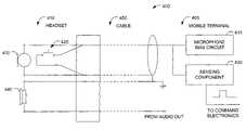
- FIG. 4is a circuit diagram for a mobile terminal to detect signaling from a push-button enabled headset in accordance with an aspect of the present invention.
- FIG. 5is a flow diagram of a methodology for fabricating a mobile terminal in accordance with an aspect of the present invention.
- FIG. 6is a flow diagram of a methodology for employing a mobile terminal with a headset in accordance with an aspect of the present invention.
- FIG. 7is a flow diagram of a high level operation of headset signaling in accordance with an aspect of the present invention.
- FIG. 8is a flow diagram of an exemplary application of push-button enabled headset in accordance with an aspect of the present invention.
- FIG. 9is a schematic illustration of an exemplary communication device in accordance with the present invention.
- the present inventionrelates to systems and methods for a mobile terminal which can operate with a plurality of types of headsets.
- the present inventionwill now be described with reference to the drawings, wherein like reference numerals are used to refer to like elements throughout.
- numerous specific detailsare set forth in order to provide a thorough understanding of the present invention. It may be evident, however, that the present invention may be practiced without these specific details. In other instances, well-known structures and devices are shown in block form in order to facilitate describing the present invention.
- a componentis intended to refer to a computer-related entity, either hardware, a combination of hardware and software, software, or software in execution.
- a componentmay be, but is not limited to, a process running on a processor, a processor, an object, an executable, a thread of execution, a program, and a computer.
- an application running on a server and the servercan be a component.
- the portable electronic device 110 in this exampleis a hand-held mobile terminal used in a wireless communication network.
- the mobile terminalcan be a cellular telephone, a Personal Digital Assistant (PDA), or any other mobile computing/communications device that can be similarly employed.
- the mobile terminal 110can operate with one of a plurality of headsets 120 .
- the plurality of headsets 120can be of one or more different types, type 1 through type N (N being an integer).
- one type of headsetcan be a commercially available audio headset and another type of headset can be a push-button enabled headset, which includes a signaling mechanism to communicate with the mobile terminal 110 .
- the mobile terminal 110can include a sensing component 130 for detecting signaling from a push-button enabled headset.
- the sensing component 130is activated if a push-button enabled type headset is employed with the mobile terminal 110 .
- the sensing component 130cannot be activated since a push-button is not present. Thus, operation of the standard headset is not impacted.
- the mobile terminal 110can optionally include a detecting component 140 for indicating whether a headset is connected to the terminal 110 .
- FIG. 2depicts a system for facilitating communication between a mobile terminal 200 and a push-button enabled headset 205 .
- the mobile terminalincludes a housing 210 , a set of user interface keys 220 for allowing a user to input information and/or operational commands and a display or touch screen 230 for displaying information and allowing the user to input information and/or operational commands.
- the mobile terminalcan also include a bar code reader (not shown) adapted to read information on a bar code label or the like.
- the user interface keys 220may include a full alphanumeric keypad, function keys, enter keys, etc.
- the mobile terminal 200further includes a sensing component (not shown) for facilitating communication with the push button enabled headset 205 .
- the sensing componentcan include active circuitry which uses switch activation to detect signaling from the push-button enabled headset 205 , which will be explained in further detail below.
- the mobile terminal 200can communicate with a standard headset over commercially available headset signaling.
- the terminal 200includes a headset receptacle jack (not shown) which can accept a plurality of different types of headsets, such as a standard, commercially available headset or a headset having a signaling button, such as push-button enabled headset 205 . If the standard headset is employed, the signaling function is not available and the standard headset operation is not impacted.
- the mobile terminal 200can also include a headset detector component (not shown) for indicating whether a headset is connected to the terminal 200 .
- the headset 205includes a support 240 for mounting on a user's head.
- the headset 205also includes a button 250 mounted to an ear piece 260 .
- the button 250is employed to provide signaling to facilitate communication between the terminal 200 and the headset 205 .
- the button 250is one type of a plurality of types of switches that can be employed and can be mounted anywhere on the headset 205 or a headset cord (not shown). Further, the button 250 could be located at a headset interface box (not shown) between the headset 205 and the mobile terminal 200 . Regardless of the location of the button 250 , employing such a button 250 relieves the user from having to reach to the mobile terminal 200 to issue commands.
- Activation of the button 250can issue simple commands to the terminal 200 , such as power-up, power-down, pick-up an incoming call, hang-up, push-to-talk, etc.
- interpretation of the button 250can be context sensitive. For example, if a phone call is incoming (e.g., ringing), activation of the button can be interpreted as a means to pick up the call. As another example, if a phone conversation is in progress, activation can be interpreted as to hang up the call.
- more complex on/off signaling schemescan be used for higher level commands (e.g., switch activation duration, periodic pulses). Though it is possible, for example, to issue voice commands to hang up during a telephony conversation, very accurate word spotting speech recognition is required and is prone to false triggers, thereby erroneously disconnecting the session.
- High level commandscan be issued by employing complex on/off signaling schemes, such as switch activation duration and periodic pulses.
- a switch activation schemea user can issue a command with sequences of button presses of various durations. There can be two switch activation durations used—a short and a long. A short press can be defined as lasting less than 1 ⁇ 3 of a second while a long press can be defined as being anything greater than 1 ⁇ 3 of a second.
- the switchesare debounced so that multiple closures due to bouncing will not be interpreted as multiple short activations.
- a sequencesuch as a double short down, for example, must have each symbol in the sequence follow the previous symbol by no more than 1 ⁇ 5 second, or any other time period defined by the system.
- the buttoncan also be a smart button, in which the action taken is inferred by the context of the system.
- the button 250is designed to provide a “context sensitive” control in which various switch combinations achieve different results.
- the context sensitive conceptrefers to the application (program) or event that is running on the terminal at a given moment. For instance, if the terminal is in telephone mode and it rings, a button push is interpreted as picking up the phone. After a few seconds of conversation a button press can signify “hang up the phone”. In normal operation, a portable terminal “goes to sleep” to conserve batteries if it is not used for a predefined time interval. In this case pushing the button can be the “wake up” or “on” command. Additionally, the interpretation of the button or switch can also be based on past, or historical, actions of the user.
- the headset 205also includes a microphone 270 such that the user can provide voice commands to the terminal 200 , or alternatively, communicate with another user or remote system.
- the microphone 270can be an electret microphone or any other suitable microphone.
- This inventiontakes advantage of the fact an electret microphone requires a bias voltage to operate. The signaling consists in generating a short across the microphone, therefore bringing the bias voltage near ground level. A level change is sensed by a circuit in the terminal and interpreted as a command.
- the electret microphoneis generally sensitive, durable, and compact in size with low power requirements.
- the electretis a modified version of the classic capacitor (or condenser) microphone, which exploits changes in capacitance due to mechanical vibrations to produce voltage variations proportional to sound waves. Whereas the condenser microphone needs an applied (phantom) voltage, the electret has a built in charge, and the few volts needed are to power a built-in FET buffer, not to create an electric field.
- the headset 300comprises a support 310 for mounting on a user's head. At least one ear piece 320 for receiving audio is mounted on the support 310 .
- the ear piece 320includes a button 330 which enables the headset 300 to communicate over commercially available headset signaling.
- the headsetcan optionally include a second ear piece 340 and a second signaling button 350 .
- a microphone 325can also be mounted on the support 310 , in which the user can communicate with other users or systems or provide voice commands to a mobile terminal.
- the microphone 325can be an electret microphone, or any other suitable microphone.
- Controls for the headsetcan be located on the headset itself as well as on the mobile terminal. Additionally, the headset and/or the mobile terminal can include communication ports (not shown) to allow the headset to receive data from other non-remote sources, such as a peripheral device. The headset can also include status indicator lights (not shown) provided on the exterior of the housing for visually displaying the system state during system operation
- the headsets in FIGS. 2 and 3have been illustrated as an over the head band design to be worn on a user's head for positioning a pair of speakers adjacent to each of the user's ears, it is to be appreciated that the headset can be of any suitable design and is contemplated as falling within the scope of the present invention.
- the headsetcan also be designed such that it is worn around a single outer ear of the use for positioning a single earphone against one of the user's ears.
- FIG. 4a system 400 for a mobile terminal 405 employing a push-button enabled type headset 410 is depicted.
- Switch activationis utilized to momentarily short a microphone bias circuit 415 .
- the microphone bias circuit 415provides bias current for a microphone 420 of the headset 410 .
- the headset 410includes a bias voltage, generally above 2V DC, for the microphone 420 .
- a push button 425 connected in parallel with the microphone 420will bring the voltage to about 0V when depressed.
- a sensing component 430 located in the terminal 405detects the voltage change and interprets such voltage change as an activation of the button 425 on the headset 410 .
- the sensing component 430can be a voltage change sense circuit, for example.
- the terminal 405monitors the microphone bias voltage and performs a context dependent function upon the sense of bias level change.
- the sensing component 430can be implemented as a comparator whose input is connected to the bias voltage that outputs a digital level, which is further monitored by digital circuitry.
- the headset 410also includes a speaker component 440 for receiving audio from the terminal 405 and/or a remote source.
- Circuitry within the mobile terminal 405can be connected to circuitry of the headset 410 via a cable 450 .
- the headsetcan wirelessly communicate with the mobile terminal, as will be explained in further detail below.
- buttonscan be implemented as a function of how the button is depressed (e.g., duration, multiple repeated pushes). If the momentary closure of the button is shorter than a predetermined minimum, the closure is determined to be accidental and is therefore ignored. In this manner, the terminal performs a switch debouncing function.
- FIGS. 5–8methodologies in accordance with various aspects of the present invention will be better appreciated with reference to FIGS. 5–8 . While, for purposes of simplicity of explanation, the methodologies of FIGS. 5–8 are shown and described as executing serially, it is to be understood and appreciated that the present invention is not limited by the illustrated order, as some aspects could, in accordance with the present invention, occur in different orders and/or concurrently with other aspects from that shown and described herein. Moreover, not all illustrated features may be required to implement a methodology in accordance with an aspect the present invention.
- FIG. 5illustrates a methodology 500 for fabricating a mobile terminal in accordance with an aspect of the invention.
- the methodologybegins at 510 where a mobile terminal is employed.
- the mobile terminalcan be a cellular telephone, a Personal Digital Assistant (PDA), or any other mobile computing/communications device that can be similarly employed.
- a sensing componentis coupled to the mobile terminal.
- the sensing componentis employed to facilitate detection of headset signaling.
- a headsetis coupled to the terminal.
- the mobile terminalcan interoperate with a plurality of types of headsets.
- the headsetcan be push-button enabled headset which includes a signaling mechanism, such as a button, to issue commands to the mobile terminal.
- the headsetcan be a standard, commercially available headset without a signaling mechanism.
- FIG. 6illustrates a methodology 600 for facilitating communication between a mobile terminal and a headset.
- the methodologybegins by coupling a headset with a mobile terminal.
- the headsetcan be a push-button enabled headset or a standard, commercially available headset. If a push-button enabled headset is coupled to the terminal, the method proceeds to 630 where communication between the mobile terminal and the headset occurs via a signaling mechanism coupled with the headset. Then, at 635 , commands are issued to the mobile terminal by activation of the signaling mechanism (e.g., button) on the headset.
- the signaling mechanisme.g., button
- the methodproceeds to 640 where the headset and mobile terminal communicate over commercially available headset signaling.
- commandsare issued to the mobile terminal via voice recognition methods or mechanical interfaces on the mobile terminal.
- FIG. 7a methodology 700 for a high level operation of push-button enabled headset signaling is depicted in accordance with an aspect of the present invention.
- the methodologybegins at 710 where a button located on a headset is activated to provide signaling to a mobile terminal. Activation of the button leads to a short in a microphone bias circuit in the mobile terminal at 720 . Then, at 730 , a sensing component on the mobile terminal detects a voltage change, which is interpreted as an activation of the button. At 740 , a command is issued to the mobile terminal based on the sense of bias level change.
- the commandmay be context sensitive, in which the command issued is dependent on the running application.
- FIG. 8illustrates a methodology 800 for employing a mobile terminal in a freezer picking application where a user picks food items from a freezer.
- the userwears a mobile terminal device on a belt under several layers of clothing.
- a headsetis connected to the terminal, wirelessly or via a cable, and provides the user with information regarding which items to pick and where such items can be located.
- the userinputs what has been picked and that he/she is ready to go on to the next item.
- the userdetermines whether he/she would like to take a break or shut down. If yes, at 850 , to extend battery life, the system shuts down or enters into suspend mode, disabling speech input.
- the userWhen the user is finished with his/her break, at 860 , the user activates a button on the headset to power it back up.
- the buttonallows the user to simply tap the inline switch and eliminates the need for the user to reach to the mobile terminal.
- the methodthen returns to 820 where the user is provided with information regarding which items to pick and where such items can be located.
- the methodologyalso returns to 820 if, at 840 , the user determines that he/she does not wish to take a break or shut down.
- a processor 905is responsible for controlling the general operation of a mobile terminal 900 .
- the processor 905is programmed to control and operate the various components within the terminal 900 in order to carry out the various functions described herein.
- the processor or CPU 905can be any of a plurality of suitable processors or micro controllers.
- a processorsuch as Intel's 8 bit microcontrollers, the 8031, 8051 or 8052, can be utilized.
- the manner in which the processor 905 can be programmed to carry out the functions relating to the present inventionwill be readily apparent to those having ordinary skill in the art based on the description provided herein.
- a memory 910 tied to the processor 905is also included in the mobile terminal 900 and serves to store program code executed by the processor 905 for carrying out operating functions of the mobile terminal 900 as described herein.
- the memory 910also serves as a storage medium for temporarily storing information such as receipt transaction information and the like.
- the memory 910is adapted to store a complete set of the information to be displayed. According to a preferred embodiment, the memory 910 has sufficient capacity to store multiple sets of information, and the processor 905 could include a program for alternating or cycling between various sets of display information.
- a display 915is coupled to the processor 905 via a display driver system 918 .
- the display 915may be a liquid crystal display (LCD) or the like.
- the display 915is operable to display data or other information relating to ordinary operation of the mobile terminal 900 .
- the display 915may display a set of customer information, which is displayed to the operator and may be transmitted over a system backbone (not shown).
- the display 915may display a variety of functions that control the execution of the mobile terminal 900 .
- the display 915is capable of displaying both alphanumeric and graphical characters.
- the display 915may be a touch screen, able to receive user information as well as display information.
- Poweris provided to the processor 905 and other components forming the terminal 900 by a battery pack 920 .
- a supplemental power source 923provides power to the processor 905
- the supplemental power source 923can be a super capacitor connected electrically in parallel with the battery 920 .
- the mobile terminal 900may enter a minimum current draw of sleep mode upon detection of a battery failure.
- the mobile terminal 900includes a communication subsystem 925 that includes a data communication port 928 , which is employed to interface the processor 905 with a remote system.
- the mobile terminal 900also optionally includes an RF section 930 connected to the processor 905 .
- the RF section 930includes an RF receiver 935 , which receives RF transmissions from the remote system for example via an antenna 940 and demodulates the signal to obtain digital information modulated therein.
- the RF section 930also includes an RF transmitter 945 for transmitting information to the remote system, for example, in response to an operator input at keypad 950 or the completion of a transaction.
- Peripheral devicessuch as a printer 955 , signature pad 960 , magnetic stripe reader 965 , touch panel 970 , and barcode scanner 975 can also be coupled to the mobile terminal through the processor 905 .
Landscapes
- Engineering & Computer Science (AREA)
- Computer Networks & Wireless Communication (AREA)
- Signal Processing (AREA)
- Telephone Function (AREA)
Abstract
Description
Claims (25)
Priority Applications (2)
| Application Number | Priority Date | Filing Date | Title |
|---|---|---|---|
| US10/172,334US7110799B1 (en) | 2002-06-14 | 2002-06-14 | Mobile terminal for interoperating with a standard or push-button enabled headset |
| US11/531,666US7620432B2 (en) | 2002-06-14 | 2006-09-13 | Mobile terminal for interoperating with a standard or push-button enabled headset |
Applications Claiming Priority (1)
| Application Number | Priority Date | Filing Date | Title |
|---|---|---|---|
| US10/172,334US7110799B1 (en) | 2002-06-14 | 2002-06-14 | Mobile terminal for interoperating with a standard or push-button enabled headset |
Related Child Applications (1)
| Application Number | Title | Priority Date | Filing Date |
|---|---|---|---|
| US11/531,666ContinuationUS7620432B2 (en) | 2002-06-14 | 2006-09-13 | Mobile terminal for interoperating with a standard or push-button enabled headset |
Publications (1)
| Publication Number | Publication Date |
|---|---|
| US7110799B1true US7110799B1 (en) | 2006-09-19 |
Family
ID=36974597
Family Applications (2)
| Application Number | Title | Priority Date | Filing Date |
|---|---|---|---|
| US10/172,334Expired - LifetimeUS7110799B1 (en) | 2002-06-14 | 2002-06-14 | Mobile terminal for interoperating with a standard or push-button enabled headset |
| US11/531,666Expired - LifetimeUS7620432B2 (en) | 2002-06-14 | 2006-09-13 | Mobile terminal for interoperating with a standard or push-button enabled headset |
Family Applications After (1)
| Application Number | Title | Priority Date | Filing Date |
|---|---|---|---|
| US11/531,666Expired - LifetimeUS7620432B2 (en) | 2002-06-14 | 2006-09-13 | Mobile terminal for interoperating with a standard or push-button enabled headset |
Country Status (1)
| Country | Link |
|---|---|
| US (2) | US7110799B1 (en) |
Cited By (32)
| Publication number | Priority date | Publication date | Assignee | Title |
|---|---|---|---|---|
| US20040081099A1 (en)* | 2002-06-24 | 2004-04-29 | Stuart Patterson | Identification system and method for recognizing any one of a number of different types of devices |
| US20040228476A1 (en)* | 2002-06-28 | 2004-11-18 | Karl Denninghoff | Method and apparatus for VoIP telephony call announcement |
| US20040260846A1 (en)* | 2002-06-24 | 2004-12-23 | George Stephan | System for verifying the identification of a device |
| US20040259435A1 (en)* | 2002-06-24 | 2004-12-23 | George Stephan | System for determining the true electrical characteristics of a device |
| US20060062382A1 (en)* | 2004-09-23 | 2006-03-23 | Sami Ronkainen | Method for describing alternative actions caused by pushing a single button |
| US20060183514A1 (en)* | 2005-02-14 | 2006-08-17 | Patton John D | Telephone and telephone accessory signal generator and methods and devices using the same |
| US20070004463A1 (en)* | 2005-07-01 | 2007-01-04 | Plantronics, Inc. | Wireless headset systems and methods for activating application programs on processor-based host |
| US20070099607A1 (en)* | 2005-11-02 | 2007-05-03 | Lg Electronics Inc. | Apparatus and method for detecting hook switch of a mobile communication terminal |
| US20070225050A1 (en)* | 2003-09-30 | 2007-09-27 | Sony Ericsson Mobile Communications Ab | Bluetooth® Enabled Hearing Aid |
| US20080026700A1 (en)* | 2006-07-26 | 2008-01-31 | Smith Richard C | Silent push-to-talk switch |
| US20080026699A1 (en)* | 2006-07-26 | 2008-01-31 | Smith Richard C | Push-to-talk switch |
| US20080166003A1 (en)* | 2007-01-06 | 2008-07-10 | Apple Inc. | Wire headset with integrated switch |
| US20080181376A1 (en)* | 2003-08-14 | 2008-07-31 | Patton John D | Telephone signal generator and methods and devices using the same |
| US20090180630A1 (en)* | 2008-01-14 | 2009-07-16 | Sander Wendell B | Electronic device circuitry for communicating with accessories |
| US20090296952A1 (en)* | 2008-05-30 | 2009-12-03 | Achim Pantfoerder | Headset microphone type detect |
| US20100054493A1 (en)* | 2008-09-03 | 2010-03-04 | Wey-Jiun Lin | Accessory controller for electronic devices |
| US7769187B1 (en) | 2009-07-14 | 2010-08-03 | Apple Inc. | Communications circuits for electronic devices and accessories |
| US20100194561A1 (en)* | 2007-07-31 | 2010-08-05 | Panasonic Corporation | Electronic circuit, electronic device, and gain control method |
| US20100260341A1 (en)* | 2009-04-10 | 2010-10-14 | Sander Wendell B | Electronic device and external equipment with configurable audio path circuitry |
| US20110128712A1 (en)* | 2009-12-01 | 2011-06-02 | Prest Christopher D | Compact media player |
| US20110194710A1 (en)* | 2009-07-27 | 2011-08-11 | Prest Christopher D | Accessory controller for electronic devices |
| US8209441B1 (en)* | 2003-12-12 | 2012-06-26 | Plantronics, Inc. | On-line status detection for host-based headset applications |
| US8611969B2 (en) | 2004-01-29 | 2013-12-17 | Surefire, Llc | Cable assembly with earpiece |
| US8625834B2 (en) | 2004-09-27 | 2014-01-07 | Surefire, Llc | Ergonomic earpiece and attachments |
| US8958573B2 (en) | 2010-12-01 | 2015-02-17 | Blackberry Limited | Apparatus, systems and methods for controlling an electronic device using an accessory |
| US20150092954A1 (en)* | 2013-09-30 | 2015-04-02 | Motorola Mobility Llc | Method and Apparatus for Sending a Control Signal to an Electronic Device |
| US9438642B2 (en) | 2012-05-01 | 2016-09-06 | Google Technology Holdings LLC | Methods for coordinating communications between a plurality of communication devices of a user |
| US9560108B2 (en) | 2012-09-13 | 2017-01-31 | Google Technology Holdings LLC | Providing a mobile access point |
| US10008814B1 (en) | 2017-02-15 | 2018-06-26 | Holster Lab LLC | Microphone muting device |
| US10044845B2 (en)* | 2014-09-05 | 2018-08-07 | Lg Electronics Inc. | Electronic device and system including the same |
| USD839243S1 (en) | 2017-09-22 | 2019-01-29 | Surefire, Llc | Earpiece |
| CN118293989A (en)* | 2024-06-06 | 2024-07-05 | 国网山东省电力公司淄博供电公司 | A telescopic shaft cable joint detection system, method and cable joint detection host |
Families Citing this family (37)
| Publication number | Priority date | Publication date | Assignee | Title |
|---|---|---|---|---|
| US7697827B2 (en) | 2005-10-17 | 2010-04-13 | Konicek Jeffrey C | User-friendlier interfaces for a camera |
| US9217868B2 (en)* | 2007-01-12 | 2015-12-22 | Kopin Corporation | Monocular display device |
| US8855719B2 (en)* | 2009-05-08 | 2014-10-07 | Kopin Corporation | Wireless hands-free computing headset with detachable accessories controllable by motion, body gesture and/or vocal commands |
| US9116340B2 (en) | 2007-05-14 | 2015-08-25 | Kopin Corporation | Mobile wireless display for accessing data from a host and method for controlling |
| US8825468B2 (en)* | 2007-07-31 | 2014-09-02 | Kopin Corporation | Mobile wireless display providing speech to speech translation and avatar simulating human attributes |
| US8355671B2 (en) | 2008-01-04 | 2013-01-15 | Kopin Corporation | Method and apparatus for transporting video signal over Bluetooth wireless interface |
| WO2009120984A1 (en) | 2008-03-28 | 2009-10-01 | Kopin Corporation | Handheld wireless display device having high-resolution display suitable for use as a mobile internet device |
| US20090262205A1 (en)* | 2008-04-21 | 2009-10-22 | Dana Stephen Smith | Voice activated headset imaging system |
| CA2729983C (en) | 2009-04-24 | 2016-07-26 | Skullcandy, Inc. | Wireless synchronization mechanism |
| WO2010129679A1 (en) | 2009-05-08 | 2010-11-11 | Kopin Corporation | Remote control of host application using motion and voice commands |
| USD623160S1 (en)* | 2009-09-15 | 2010-09-07 | Garn Dale W | Simplified cell telephone |
| US9203489B2 (en) | 2010-05-05 | 2015-12-01 | Google Technology Holdings LLC | Method and precoder information feedback in multi-antenna wireless communication systems |
| US9377862B2 (en) | 2010-09-20 | 2016-06-28 | Kopin Corporation | Searchlight navigation using headtracker to reveal hidden or extra document data |
| US10013976B2 (en) | 2010-09-20 | 2018-07-03 | Kopin Corporation | Context sensitive overlays in voice controlled headset computer displays |
| US8706170B2 (en) | 2010-09-20 | 2014-04-22 | Kopin Corporation | Miniature communications gateway for head mounted display |
| US8736516B2 (en) | 2010-09-20 | 2014-05-27 | Kopin Corporation | Bluetooth or other wireless interface with power management for head mounted display |
| US9316827B2 (en) | 2010-09-20 | 2016-04-19 | Kopin Corporation | LifeBoard—series of home pages for head mounted displays (HMD) that respond to head tracking |
| US8862186B2 (en) | 2010-09-21 | 2014-10-14 | Kopin Corporation | Lapel microphone micro-display system incorporating mobile information access system |
| CN109116985A (en) | 2011-05-10 | 2019-01-01 | 寇平公司 | The method that control information is shown |
| US8929954B2 (en) | 2012-04-25 | 2015-01-06 | Kopin Corporation | Headset computer (HSC) as auxiliary display with ASR and HT input |
| US9442290B2 (en) | 2012-05-10 | 2016-09-13 | Kopin Corporation | Headset computer operation using vehicle sensor feedback for remote control vehicle |
| US9378028B2 (en) | 2012-05-31 | 2016-06-28 | Kopin Corporation | Headset computer (HSC) with docking station and dual personality |
| US9210500B2 (en)* | 2012-08-17 | 2015-12-08 | Cirrus Logic, Inc. | Headset type detection and configuration techniques |
| US9813262B2 (en) | 2012-12-03 | 2017-11-07 | Google Technology Holdings LLC | Method and apparatus for selectively transmitting data using spatial diversity |
| US9591508B2 (en) | 2012-12-20 | 2017-03-07 | Google Technology Holdings LLC | Methods and apparatus for transmitting data between different peer-to-peer communication groups |
| US9160064B2 (en) | 2012-12-28 | 2015-10-13 | Kopin Corporation | Spatially diverse antennas for a headset computer |
| US9979531B2 (en) | 2013-01-03 | 2018-05-22 | Google Technology Holdings LLC | Method and apparatus for tuning a communication device for multi band operation |
| US9620144B2 (en) | 2013-01-04 | 2017-04-11 | Kopin Corporation | Confirmation of speech commands for control of headset computers |
| US9134793B2 (en) | 2013-01-04 | 2015-09-15 | Kopin Corporation | Headset computer with head tracking input used for inertial control |
| JP6423799B2 (en) | 2013-01-04 | 2018-11-14 | コピン コーポレーション | Ad hoc network |
| US9301085B2 (en) | 2013-02-20 | 2016-03-29 | Kopin Corporation | Computer headset with detachable 4G radio |
| US10229697B2 (en) | 2013-03-12 | 2019-03-12 | Google Technology Holdings LLC | Apparatus and method for beamforming to obtain voice and noise signals |
| US9549290B2 (en) | 2013-12-19 | 2017-01-17 | Google Technology Holdings LLC | Method and apparatus for determining direction information for a wireless device |
| US9369557B2 (en) | 2014-03-05 | 2016-06-14 | Cirrus Logic, Inc. | Frequency-dependent sidetone calibration |
| US9491007B2 (en) | 2014-04-28 | 2016-11-08 | Google Technology Holdings LLC | Apparatus and method for antenna matching |
| TWI566124B (en)* | 2014-10-01 | 2017-01-11 | 瑞昱半導體股份有限公司 | Audio codec, portable electronic apparatus and button control method |
| US10412479B2 (en) | 2015-07-17 | 2019-09-10 | Cirrus Logic, Inc. | Headset management by microphone terminal characteristic detection |
Citations (12)
| Publication number | Priority date | Publication date | Assignee | Title |
|---|---|---|---|---|
| US5978689A (en)* | 1997-07-09 | 1999-11-02 | Tuoriniemi; Veijo M. | Personal portable communication and audio system |
| US6272361B1 (en)* | 1997-07-16 | 2001-08-07 | Nokia Mobile Phones Limited | Radio telephone |
| US6292560B1 (en) | 1998-10-16 | 2001-09-18 | Mitel Corporation | Click-free muting circuit for headset |
| US20020037746A1 (en)* | 2000-09-22 | 2002-03-28 | Keiji Osano | Hand held telephone set and audio processing method |
| US20020068600A1 (en)* | 2000-06-21 | 2002-06-06 | Hiroyuki Chihara | Mobile video telephone system |
| US20020133545A1 (en)* | 2001-03-19 | 2002-09-19 | Fano Andrew E. | Mobile valet |
| US6459882B1 (en)* | 1995-05-18 | 2002-10-01 | Aura Communications, Inc. | Inductive communication system and method |
| US20030060242A1 (en)* | 2001-09-27 | 2003-03-27 | Kevin Dotzler | Microphone switchover circuit |
| US6594366B1 (en)* | 1997-12-02 | 2003-07-15 | Siemens Information & Communication Networks, Inc. | Headset/radio auto sensing jack |
| US6597786B1 (en)* | 2000-05-19 | 2003-07-22 | Kuan-Nong Lin | Headset/hand-free operating mode selecting and switching system for telephone |
| US6856046B1 (en)* | 2002-03-08 | 2005-02-15 | Analog Devices, Inc. | Plug-in device discrimination circuit and method |
| US6871047B2 (en)* | 2000-10-17 | 2005-03-22 | Nec Corporation | Radio communication connection destination specifying method |
- 2002
- 2002-06-14USUS10/172,334patent/US7110799B1/ennot_activeExpired - Lifetime
- 2006
- 2006-09-13USUS11/531,666patent/US7620432B2/ennot_activeExpired - Lifetime
Patent Citations (12)
| Publication number | Priority date | Publication date | Assignee | Title |
|---|---|---|---|---|
| US6459882B1 (en)* | 1995-05-18 | 2002-10-01 | Aura Communications, Inc. | Inductive communication system and method |
| US5978689A (en)* | 1997-07-09 | 1999-11-02 | Tuoriniemi; Veijo M. | Personal portable communication and audio system |
| US6272361B1 (en)* | 1997-07-16 | 2001-08-07 | Nokia Mobile Phones Limited | Radio telephone |
| US6594366B1 (en)* | 1997-12-02 | 2003-07-15 | Siemens Information & Communication Networks, Inc. | Headset/radio auto sensing jack |
| US6292560B1 (en) | 1998-10-16 | 2001-09-18 | Mitel Corporation | Click-free muting circuit for headset |
| US6597786B1 (en)* | 2000-05-19 | 2003-07-22 | Kuan-Nong Lin | Headset/hand-free operating mode selecting and switching system for telephone |
| US20020068600A1 (en)* | 2000-06-21 | 2002-06-06 | Hiroyuki Chihara | Mobile video telephone system |
| US20020037746A1 (en)* | 2000-09-22 | 2002-03-28 | Keiji Osano | Hand held telephone set and audio processing method |
| US6871047B2 (en)* | 2000-10-17 | 2005-03-22 | Nec Corporation | Radio communication connection destination specifying method |
| US20020133545A1 (en)* | 2001-03-19 | 2002-09-19 | Fano Andrew E. | Mobile valet |
| US20030060242A1 (en)* | 2001-09-27 | 2003-03-27 | Kevin Dotzler | Microphone switchover circuit |
| US6856046B1 (en)* | 2002-03-08 | 2005-02-15 | Analog Devices, Inc. | Plug-in device discrimination circuit and method |
Cited By (86)
| Publication number | Priority date | Publication date | Assignee | Title |
|---|---|---|---|---|
| US20100146154A9 (en)* | 2002-06-24 | 2010-06-10 | George Stephan | System for verifying the identification of a device |
| US7890284B2 (en)* | 2002-06-24 | 2011-02-15 | Analog Devices, Inc. | Identification system and method for recognizing any one of a number of different types of devices |
| US20040260846A1 (en)* | 2002-06-24 | 2004-12-23 | George Stephan | System for verifying the identification of a device |
| US20040259435A1 (en)* | 2002-06-24 | 2004-12-23 | George Stephan | System for determining the true electrical characteristics of a device |
| US20040081099A1 (en)* | 2002-06-24 | 2004-04-29 | Stuart Patterson | Identification system and method for recognizing any one of a number of different types of devices |
| US7912668B2 (en) | 2002-06-24 | 2011-03-22 | Analog Devices, Inc. | System for determining the true electrical characteristics of a device |
| US20100112875A9 (en)* | 2002-06-24 | 2010-05-06 | George Stephan | System for determining the true electrical characteristics of a device |
| US7783058B2 (en) | 2002-06-24 | 2010-08-24 | Analog Devices, Inc. | System for verifying the identification of a device |
| US20040228476A1 (en)* | 2002-06-28 | 2004-11-18 | Karl Denninghoff | Method and apparatus for VoIP telephony call announcement |
| US7532732B2 (en)* | 2002-06-28 | 2009-05-12 | Intel Corporation | Method and apparatus for VoIP telephony call announcement |
| US8078235B2 (en) | 2003-08-14 | 2011-12-13 | Patton John D | Telephone signal generator and methods and devices using the same |
| US20080181376A1 (en)* | 2003-08-14 | 2008-07-31 | Patton John D | Telephone signal generator and methods and devices using the same |
| US7570974B2 (en)* | 2003-09-30 | 2009-08-04 | Sony Ericsson Mobile Communications Ab | Bluetooth® enabled hearing aid |
| US20070225050A1 (en)* | 2003-09-30 | 2007-09-27 | Sony Ericsson Mobile Communications Ab | Bluetooth® Enabled Hearing Aid |
| US8209441B1 (en)* | 2003-12-12 | 2012-06-26 | Plantronics, Inc. | On-line status detection for host-based headset applications |
| US10440459B2 (en) | 2004-01-29 | 2019-10-08 | Surefire, Llc | Ergonomic earpiece |
| US20200252711A1 (en)* | 2004-01-29 | 2020-08-06 | Surefire, Llc | Ergonomic earpiece |
| US8611969B2 (en) | 2004-01-29 | 2013-12-17 | Surefire, Llc | Cable assembly with earpiece |
| US9479856B2 (en) | 2004-01-29 | 2016-10-25 | Surefire, Llc | Ergonomic earpiece |
| US9042947B2 (en) | 2004-01-29 | 2015-05-26 | Surefire, Llc | Multiple input acoustic coupler |
| US7721227B2 (en)* | 2004-09-23 | 2010-05-18 | Nokia Corporation | Method for describing alternative actions caused by pushing a single button |
| US20060062382A1 (en)* | 2004-09-23 | 2006-03-23 | Sami Ronkainen | Method for describing alternative actions caused by pushing a single button |
| US8625834B2 (en) | 2004-09-27 | 2014-01-07 | Surefire, Llc | Ergonomic earpiece and attachments |
| US9560436B2 (en) | 2004-09-27 | 2017-01-31 | Surefire, Llc | Ergonomic earpiece and attachments |
| US10200778B2 (en) | 2004-09-27 | 2019-02-05 | Surefire, Llc | Earpiece with ergonomic extension |
| US10231048B2 (en) | 2004-09-27 | 2019-03-12 | Surefire, Llc | Ergonomic earpiece with attachment mount |
| US20060183514A1 (en)* | 2005-02-14 | 2006-08-17 | Patton John D | Telephone and telephone accessory signal generator and methods and devices using the same |
| US7599719B2 (en)* | 2005-02-14 | 2009-10-06 | John D. Patton | Telephone and telephone accessory signal generator and methods and devices using the same |
| US8755845B2 (en)* | 2005-07-01 | 2014-06-17 | Plantronics, Inc. | Wireless headset systems and methods for activating application programs on processor-based host |
| US20070004463A1 (en)* | 2005-07-01 | 2007-01-04 | Plantronics, Inc. | Wireless headset systems and methods for activating application programs on processor-based host |
| US20070099607A1 (en)* | 2005-11-02 | 2007-05-03 | Lg Electronics Inc. | Apparatus and method for detecting hook switch of a mobile communication terminal |
| US7620434B2 (en)* | 2005-11-02 | 2009-11-17 | Lg Electronics Inc. | Apparatus and method for detecting hook switch of a mobile communication terminal |
| US8548395B2 (en) | 2006-07-26 | 2013-10-01 | Surefire, Llc | Push-to-talk switch |
| US20080026699A1 (en)* | 2006-07-26 | 2008-01-31 | Smith Richard C | Push-to-talk switch |
| US20080026700A1 (en)* | 2006-07-26 | 2008-01-31 | Smith Richard C | Silent push-to-talk switch |
| US20080166003A1 (en)* | 2007-01-06 | 2008-07-10 | Apple Inc. | Wire headset with integrated switch |
| US8144915B2 (en) | 2007-01-06 | 2012-03-27 | Apple Inc. | Wired headset with integrated switch |
| US8842871B2 (en) | 2007-01-06 | 2014-09-23 | M. Evans Hankey | Wired headset with integrated switch |
| US20100194561A1 (en)* | 2007-07-31 | 2010-08-05 | Panasonic Corporation | Electronic circuit, electronic device, and gain control method |
| US8983093B2 (en) | 2008-01-14 | 2015-03-17 | Apple Inc. | Electronic device circuitry for communicating with accessories |
| US8976976B2 (en) | 2008-01-14 | 2015-03-10 | Apple Inc. | Accessory adapter with user input interface |
| US20090180630A1 (en)* | 2008-01-14 | 2009-07-16 | Sander Wendell B | Electronic device circuitry for communicating with accessories |
| US20090180629A1 (en)* | 2008-01-14 | 2009-07-16 | Sander Wendell B | Methods of calibrating tone-based communications systems |
| US20090182913A1 (en)* | 2008-01-14 | 2009-07-16 | Apple Inc. | Data store and enhanced features for headset of portable media device |
| US20090180642A1 (en)* | 2008-01-14 | 2009-07-16 | Sander Wendell B | Accessory adapter with user input interface |
| US9680980B2 (en) | 2008-01-14 | 2017-06-13 | Apple Inc. | Electronic device accessory |
| US20090180643A1 (en)* | 2008-01-14 | 2009-07-16 | Sander Wendell B | Electronic device circuitry for communicating with accessories |
| US20090180659A1 (en)* | 2008-01-14 | 2009-07-16 | Sander Wendell B | Electronic device accessory with ultrasonic tone generator |
| US9215304B2 (en) | 2008-01-14 | 2015-12-15 | Apple Inc. | Data store and enhanced features for headset of portable media device |
| US20090179768A1 (en)* | 2008-01-14 | 2009-07-16 | Sander Wendell B | Electronic device accessory |
| US8995689B2 (en) | 2008-01-14 | 2015-03-31 | Apple Inc. | Electronic device circuitry for communicating with accessories |
| US8600080B2 (en) | 2008-01-14 | 2013-12-03 | Apple Inc. | Methods for communicating with electronic device accessories |
| US7627128B2 (en) | 2008-01-14 | 2009-12-01 | Apple Inc. | Methods of calibrating tone-based communications systems |
| US7623667B2 (en) | 2008-01-14 | 2009-11-24 | Apple Inc. | Electronic device accessory with ultrasonic tone generator |
| US20090180353A1 (en)* | 2008-01-14 | 2009-07-16 | Sander Wendell B | Methods for using an accessory to communicate with an electronic device |
| US7869608B2 (en) | 2008-01-14 | 2011-01-11 | Apple Inc. | Electronic device accessory |
| US20090179789A1 (en)* | 2008-01-14 | 2009-07-16 | Apple Inc. | Electronic device control based on user gestures applied to a media headset |
| US20090180354A1 (en)* | 2008-01-14 | 2009-07-16 | Sander Wendell B | Methods for communicating with electronic device accessories |
| US8891790B2 (en) | 2008-01-14 | 2014-11-18 | Apple Inc. | Methods for using an accessory to communicate with an electronic device |
| US20090296952A1 (en)* | 2008-05-30 | 2009-12-03 | Achim Pantfoerder | Headset microphone type detect |
| US8861743B2 (en)* | 2008-05-30 | 2014-10-14 | Apple Inc. | Headset microphone type detect |
| US20100054493A1 (en)* | 2008-09-03 | 2010-03-04 | Wey-Jiun Lin | Accessory controller for electronic devices |
| US8995677B2 (en) | 2008-09-03 | 2015-03-31 | Apple Inc. | Accessory controller for electronic devices |
| US8254592B2 (en) | 2009-04-10 | 2012-08-28 | Apple Inc. | Electronic device and external equipment with configurable audio path circuitry |
| US20100260362A1 (en)* | 2009-04-10 | 2010-10-14 | Sander Wendell B | Electronic device and external equipment with configurable audio path circuitry |
| US20100260341A1 (en)* | 2009-04-10 | 2010-10-14 | Sander Wendell B | Electronic device and external equipment with configurable audio path circuitry |
| US8019096B2 (en) | 2009-04-10 | 2011-09-13 | Apple Inc. | Electronic device and external equipment with configurable audio path circuitry |
| US7769187B1 (en) | 2009-07-14 | 2010-08-03 | Apple Inc. | Communications circuits for electronic devices and accessories |
| US9064653B2 (en) | 2009-07-27 | 2015-06-23 | Apple Inc. | Accessory controller for electronic devices |
| US8314354B2 (en) | 2009-07-27 | 2012-11-20 | Apple Inc. | Accessory controller for electronic devices |
| US8658926B2 (en) | 2009-07-27 | 2014-02-25 | Apple Inc. | Accessory controller for electronic devices |
| US8853581B2 (en) | 2009-07-27 | 2014-10-07 | Apple Inc. | Accessory controller for electronic devices |
| US20110194710A1 (en)* | 2009-07-27 | 2011-08-11 | Prest Christopher D | Accessory controller for electronic devices |
| US8724339B2 (en) | 2009-12-01 | 2014-05-13 | Apple Inc. | Compact media player |
| US10292291B2 (en) | 2009-12-01 | 2019-05-14 | Apple Inc. | Compact media player |
| US9961792B2 (en) | 2009-12-01 | 2018-05-01 | Apple Inc. | Compact media player |
| US20110128712A1 (en)* | 2009-12-01 | 2011-06-02 | Prest Christopher D | Compact media player |
| US8958573B2 (en) | 2010-12-01 | 2015-02-17 | Blackberry Limited | Apparatus, systems and methods for controlling an electronic device using an accessory |
| US9930125B2 (en) | 2012-05-01 | 2018-03-27 | Google Technology Holdings LLC | Methods for coordinating communications between a plurality of communication devices of a user |
| US9438642B2 (en) | 2012-05-01 | 2016-09-06 | Google Technology Holdings LLC | Methods for coordinating communications between a plurality of communication devices of a user |
| US9560108B2 (en) | 2012-09-13 | 2017-01-31 | Google Technology Holdings LLC | Providing a mobile access point |
| US20150092954A1 (en)* | 2013-09-30 | 2015-04-02 | Motorola Mobility Llc | Method and Apparatus for Sending a Control Signal to an Electronic Device |
| US10044845B2 (en)* | 2014-09-05 | 2018-08-07 | Lg Electronics Inc. | Electronic device and system including the same |
| US10008814B1 (en) | 2017-02-15 | 2018-06-26 | Holster Lab LLC | Microphone muting device |
| USD839243S1 (en) | 2017-09-22 | 2019-01-29 | Surefire, Llc | Earpiece |
| CN118293989A (en)* | 2024-06-06 | 2024-07-05 | 国网山东省电力公司淄博供电公司 | A telescopic shaft cable joint detection system, method and cable joint detection host |
Also Published As
| Publication number | Publication date |
|---|---|
| US7620432B2 (en) | 2009-11-17 |
| US20070010288A1 (en) | 2007-01-11 |
Similar Documents
| Publication | Publication Date | Title |
|---|---|---|
| US7110799B1 (en) | Mobile terminal for interoperating with a standard or push-button enabled headset | |
| US20160036996A1 (en) | Electronic device with static electric field sensor and related method | |
| CN100583658C (en) | Sensor screen power saver | |
| US8793519B2 (en) | Method for reducing power consumption based on motion sensor and portable terminal using the same | |
| EP2881939B1 (en) | System for speech keyword detection and associated method | |
| EP2637393B1 (en) | Automated Response to and Sensing of User Activity in Portable Devices | |
| CN101720550B (en) | Dynamic routing of audio among multiple audio devices | |
| US20090280872A1 (en) | Mobile apparatus | |
| CN102291482B (en) | Method for power management of mobile communication terminal and mobile communication terminal using this method | |
| US20080191892A1 (en) | System and method for providing improved detection of user inaction | |
| JP4706629B2 (en) | Mobile terminal device | |
| US20100279661A1 (en) | Portable electronic device | |
| CN101889431A (en) | Interacting with devices based on physical device-to-device contact | |
| CN110417866B (en) | Door lock control method and device | |
| CN106445596B (en) | Method and device for managing setting items | |
| KR20100052287A (en) | Control method of portable device connected external device and system thereof | |
| US8620392B2 (en) | Electronic device capable of continuing a telephone call when charging | |
| CN109101290A (en) | It is a kind of fast to control setting method, terminal and computer readable storage medium | |
| US20060284848A1 (en) | System and method for saving power | |
| CN109144454A (en) | double-sided screen display control method and related product | |
| WO2022042485A1 (en) | Control method and apparatus for near-field communication module, and electronic device | |
| CN105094822A (en) | Terminal device control method and device | |
| CN109947484A (en) | A kind of control method, terminal and computer readable storage medium waking up lock | |
| JP2003244066A (en) | Mobile phone, control method thereof, and program | |
| CN106921793B (en) | information prompting method and device and mobile terminal |
Legal Events
| Date | Code | Title | Description |
|---|---|---|---|
| AS | Assignment | Owner name:SYMBOL TECHNOLOGIES, INC., NEW YORK Free format text:ASSIGNMENT OF ASSIGNORS INTEREST;ASSIGNORS:WILLINS, BRUCE A.;STRAT, ASKOLD;REEL/FRAME:013189/0907;SIGNING DATES FROM 20020708 TO 20020715 | |
| STCF | Information on status: patent grant | Free format text:PATENTED CASE | |
| CC | Certificate of correction | ||
| FPAY | Fee payment | Year of fee payment:4 | |
| FPAY | Fee payment | Year of fee payment:8 | |
| AS | Assignment | Owner name:MORGAN STANLEY SENIOR FUNDING, INC. AS THE COLLATERAL AGENT, MARYLAND Free format text:SECURITY AGREEMENT;ASSIGNORS:ZIH CORP.;LASER BAND, LLC;ZEBRA ENTERPRISE SOLUTIONS CORP.;AND OTHERS;REEL/FRAME:034114/0270 Effective date:20141027 Owner name:MORGAN STANLEY SENIOR FUNDING, INC. AS THE COLLATE Free format text:SECURITY AGREEMENT;ASSIGNORS:ZIH CORP.;LASER BAND, LLC;ZEBRA ENTERPRISE SOLUTIONS CORP.;AND OTHERS;REEL/FRAME:034114/0270 Effective date:20141027 | |
| AS | Assignment | Owner name:SYMBOL TECHNOLOGIES, LLC, NEW YORK Free format text:CHANGE OF NAME;ASSIGNOR:SYMBOL TECHNOLOGIES, INC.;REEL/FRAME:036083/0640 Effective date:20150410 | |
| AS | Assignment | Owner name:SYMBOL TECHNOLOGIES, INC., NEW YORK Free format text:RELEASE BY SECURED PARTY;ASSIGNOR:MORGAN STANLEY SENIOR FUNDING, INC.;REEL/FRAME:036371/0738 Effective date:20150721 | |
| MAFP | Maintenance fee payment | Free format text:PAYMENT OF MAINTENANCE FEE, 12TH YEAR, LARGE ENTITY (ORIGINAL EVENT CODE: M1553) Year of fee payment:12 |