US7110391B1 - Transporting telephony signaling over a data network - Google Patents
Transporting telephony signaling over a data networkDownload PDFInfo
- Publication number
- US7110391B1 US7110391B1US09/517,903US51790300AUS7110391B1US 7110391 B1US7110391 B1US 7110391B1US 51790300 AUS51790300 AUS 51790300AUS 7110391 B1US7110391 B1US 7110391B1
- Authority
- US
- United States
- Prior art keywords
- stimulus
- packet
- control information
- interface
- packets
- Prior art date
- Legal status (The legal status is an assumption and is not a legal conclusion. Google has not performed a legal analysis and makes no representation as to the accuracy of the status listed.)
- Expired - Fee Related
Links
- 230000011664signalingEffects0.000titledescription5
- 238000000034methodMethods0.000claimsdescription21
- 230000005540biological transmissionEffects0.000claimsdescription5
- 238000005538encapsulationMethods0.000claimsdescription5
- 230000004913activationEffects0.000claimsdescription4
- 230000006835compressionEffects0.000claimsdescription3
- 238000007906compressionMethods0.000claimsdescription3
- 238000004891communicationMethods0.000description14
- 238000012545processingMethods0.000description7
- 238000010586diagramMethods0.000description6
- 230000015654memoryEffects0.000description5
- 230000008569processEffects0.000description5
- 238000013519translationMethods0.000description5
- 230000008901benefitEffects0.000description4
- 230000008878couplingEffects0.000description3
- 238000010168coupling processMethods0.000description3
- 238000005859coupling reactionMethods0.000description3
- 230000006870functionEffects0.000description3
- 238000012986modificationMethods0.000description3
- 230000004048modificationEffects0.000description3
- 238000012546transferMethods0.000description3
- 238000013459approachMethods0.000description2
- 238000006243chemical reactionMethods0.000description2
- 230000003287optical effectEffects0.000description2
- 230000001360synchronised effectEffects0.000description2
- 238000002405diagnostic procedureMethods0.000description1
- 238000004519manufacturing processMethods0.000description1
- 230000008672reprogrammingEffects0.000description1
- 239000004065semiconductorSubstances0.000description1
- 230000003068static effectEffects0.000description1
Images


Classifications
- H—ELECTRICITY
- H04—ELECTRIC COMMUNICATION TECHNIQUE
- H04M—TELEPHONIC COMMUNICATION
- H04M7/00—Arrangements for interconnection between switching centres
- H04M7/12—Arrangements for interconnection between switching centres for working between exchanges having different types of switching equipment, e.g. power-driven and step by step or decimal and non-decimal
- H04M7/1205—Arrangements for interconnection between switching centres for working between exchanges having different types of switching equipment, e.g. power-driven and step by step or decimal and non-decimal where the types of switching equipement comprises PSTN/ISDN equipment and switching equipment of networks other than PSTN/ISDN, e.g. Internet Protocol networks
- H04M7/1225—Details of core network interconnection arrangements
- H04M7/123—Details of core network interconnection arrangements where the packet-switched network is an Internet Protocol Multimedia System-type network
- H—ELECTRICITY
- H04—ELECTRIC COMMUNICATION TECHNIQUE
- H04L—TRANSMISSION OF DIGITAL INFORMATION, e.g. TELEGRAPHIC COMMUNICATION
- H04L65/00—Network arrangements, protocols or services for supporting real-time applications in data packet communication
- H04L65/1066—Session management
- H04L65/1101—Session protocols
- H—ELECTRICITY
- H04—ELECTRIC COMMUNICATION TECHNIQUE
- H04M—TELEPHONIC COMMUNICATION
- H04M7/00—Arrangements for interconnection between switching centres
- H04M7/006—Networks other than PSTN/ISDN providing telephone service, e.g. Voice over Internet Protocol (VoIP), including next generation networks with a packet-switched transport layer
- H—ELECTRICITY
- H04—ELECTRIC COMMUNICATION TECHNIQUE
- H04Q—SELECTING
- H04Q3/00—Selecting arrangements
- H04Q3/0016—Arrangements providing connection between exchanges
- H04Q3/0025—Provisions for signalling
Definitions
- the inventionrelates to transporting telephony signaling, such as stimulus messages for a digital telephone, over a data network.
- Private telephony exchange systemsmay include private branch exchange (PBX) systems, key telephone systems, and Centrex systems (in which a central office exchange provides PBX-like switching for a special line group).
- PBXprivate branch exchange
- CentrexCentrex systems
- a private telephone exchange systemis characterized by a simplified number plan that identifies extensions by five or less digit numbers, depending upon the size of the exchange system. This is in contrast to a minimum of seven digits (or even ten) typically employed for a directory number serviced by a public central office exchange.
- Private telephone exchange systemsmay also offer other services, such as voice mail, intercom, message waiting indication, and other features.
- a private telephone exchange systemincludes interface circuits (e.g., line cards of a PBX system) to communicate with various telephony devices, which may include digital telephones.
- Native stimulus messagesmay be exchanged between the telephones (which may also be referred to as “stimulus telephones”) and the private telephone exchange system for performing calls.
- the types of stimulus messages that are exchanged between a stimulus telephone and the private telephone systemincludes the stimulus telephone reporting key press and hook state events to the switch system, and the switch system communicating commands to the stimulus telephone to cause activation of the telephone's ringer, control of the telephone's display, and activation and connection of the telephone's handset to the audio path.
- the stimulus telephonesare connected to the exchange system over a number of corresponding lines.
- a feature offered by the private telephone exchange systemis that the number of lines coupling the telephones may exceed the number of central office lines that the exchange system is coupled to.
- a first number of central office linesmay be shared by a second number of telephones through the telephone exchange system, with the second number typically much larger than the first number.
- Stimulus telephonesrely on the telephone exchange system for performing various functions. As such, stimulus telephones are not provided with much intelligence. However, advantages of stimulus telephones are that they are relatively cheap to manufacture and are not complex.
- TCMtime compression multiplex
- the digital information signal to be transmittedis divided into discrete portions, with each portion time compressed to form a “burst” that occupies less than one half the time of the original portion.
- the transmitter at each terminal connected to the TCM linkalternately transmits the burst onto the link, following which the associated receiver at each terminal can receive a corresponding burst from the other transmitter.
- each burstis expanded to occupy its original time span.
- the systemappears to be transmitting the two digital information streams continuously and simultaneously (full-duplex communication).
- interfacesfor carrying stimulus messages between a stimulus telephone and a private telephone exchange system.
- Such interfacesare typically proprietary and may differ depending on the manufacturer of the telephone exchange system and stimulus telephones.
- private telephone exchange systemsmay be limited in geographical reach. Thus, typically, a private telephone exchange system is employed at a location in which telephone sets are relatively close to the telephone exchange system. As the size of a facility grows, additional private telephone exchange systems may be added to increase capacity and to provide service for different segments of the facility.
- private telephone exchange systemsusually do not reach remote sites (such as remote office location or a home office location) using conventional links between stimulus telephones and the private telephone exchange system.
- remote sitessuch as remote office location or a home office location
- different setupsare typically provided.
- the usermay subscribe to a dedicated central office line for communicating over the public switched telephone network (PSTN).
- PSTNpublic switched telephone network
- a separate exchange systemsuch as a key telephone system may be employed to support those users.
- usersare not hooked into the one or more private telephone exchange systems at the main office location. This prevents convenient user access to various features offered by such private telephone exchange systems, such as voice mail, extension dialing using a reduced number of digits, and intercom features.
- a LANlocal area network
- computers, servers, gateways, routers, and other devicesto enable data communications over the LAN between the network elements.
- the presence of separate lines for telephony services and for data servicesmay be associated with increased costs.
- an apparatus for use in a telephony systemincludes a digital interface to communicate with a stimulus device and a packet interface to communicate with a packet-based network.
- a controllerreceives stimulus control information from the digital interface and encapsulates the stimulus control information into one or more packets for transmission over the packet-based network through the packet interface.
- Some embodiments of the inventionmay include one or more of the following advantages.
- a packet-based data networkto communicate stimulus messages exchanged between stimulus telephones and a telephone exchange system
- dedicated lines for telephony services that are separate from the packet-based communications linescan be avoided or reduced. This may reduce costs associated with setting up an office facility.
- Using packet-based data networksmay also facilitate the linking of stimulus telephones at remote locations, such as remote office sites or home office locations, to the main office telephone exchange system.
- FIG. 1Ais a block diagram of an embodiment of a telephony system.
- FIG. 1Bis a block diagram of another embodiment of a telephony system.
- FIG. 2illustrates a stimulus telephone and an interface device coupled to the stimulus telephone in accordance with an embodiment.
- FIGS. 3A–3Billustrate the communications of stimulus messages between a stimulus telephone and a packet-based data network in accordance with one embodiment.
- FIG. 4is a block diagram of a stimulus telephone in accordance with one embodiment for use in the telephony system of FIG. 1A or 1 B.
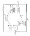
- FIG. 5is a block diagram of components in an interface device coupled between the stimulus telephone and the data network in accordance with one embodiment.
- FIG. 6is a flow diagram for processing outbound messages, in the interface device of FIG. 4 , from a stimulus telephone to the data network.
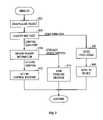
- FIG. 7is a flow diagram for processing inbound messages, in the interface device, from the data network to the stimulus telephone.
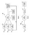
- a telephony system 10includes a packet-based data network 12 to which various network elements may be coupled.
- the network elementsmay include a private telephone exchange system, such as a private branch exchange (PBX) system or a key telephone system.
- Other network elements that may be coupled to the data network 12include interface devices 16 A, 16 B, and 16 C, that are in turn coupled to preselected ports of stimulus telephones 18 A, 18 B, and 18 C, respectively.
- Other end user devicesinstead of the stimulus telephones 18 A, 18 B, and 18 C may be employed in other arrangements.
- Such other end user devicesmay include speaker phones, conference phones, and any other device that enables voice communications.
- the telephones 18 A, 18 B, and 18 C and such other devicesmay be generally referred to as “stimulus devices.”
- the interface devices 16 A, 16 B, and 16 Cencapsulate stimulus messages for communication over the data network 12 from the stimulus telephones 18 to the telephone exchange system 14 .
- the interface devices 16 A, 16 B, and 16 Cdecapsulate messages received over the data network 12 into stimulus messages for communication to respective stimulus telephones 18 A, 18 B, and 18 C.
- the telephone exchange system 14is data network-enabled and may be directly coupled to the data network 12 through internal interface circuits.
- the stimulus telephone 18may provide a port, slot, or receptacle 17 for receiving an interface device 16 (one of 16 A, 16 B, and 16 C).
- the interface device in the illustrated embodimentis in the form of a card having a connector to couple to a corresponding connector of the receptacle 17 .
- the interface device 16may be a separate module coupled to a port of the telephone 18 by a cable.
- the stimulus telephone 18 Cmay include a second port that may couple the stimulus telephone 18 C directly over a link 20 to the telephone exchange system 14 .
- a link 20may be a time compression multiplex (TCM) link, for example.
- TCMtime compression multiplex
- Other types of links between the stimulus telephone 18 C and the PBX 14may be employed in further embodiments, with the interfaces between the stimulus telephone 18 C and the telephone exchange system 14 depending upon the manufacturer of the equipment.
- the other stimulus telephones 18 A and 18 B in the telephony system 10may include similar ports for coupling the stimulus telephones 18 A and 18 B directly to the telephone exchange system 14 .
- a “data network” or “network”may refer to one or more communications networks, channels, links, or paths, and systems or devices (such as routers) used to route data over such networks, channels, links, or paths.
- the packet-based data network 12may include a packet-switched data network such as an Internet Protocol (IP) network over which packets, datagrams, or other units of data are communicated.
- IPInternet Protocol
- RFCRequest for Comments
- Other versions of IPsuch as IPv6, or other connectionless, packet-switched standards may also be utilized in further embodiments.
- a version of IPv6is described in RFC 2460, entitled “Internet Protocol, Version 6 (IPv6) Specification,” dated December 1998.
- a packet-switched networkis one in which the same path may be shared by several network elements.
- Packet-switched networkssuch as IP networks are based on a connectionless internetwork layer. Packets or other units of data injected into a packet-switched data network may travel independently over any path (and possibly over different paths) to a destination point. The packets may even arrive out of order. Routing of the packets is based on one or more addresses carried in each packet.
- Packet-based data networksmay also include connection-oriented networks, such as Asynchronous Transfer Mode (ATM) and Frame Relay networks.
- ATMAsynchronous Transfer Mode
- Frame Relay networksIn a connection-oriented packet-based network, a virtual circuit or connection is established between two end points. In such connection-oriented networks, packets are received in the same order in which they were transmitted.
- the packet-based data network 12may also be used to link other types of network elements ( 22 ), such as personal computers, servers, gateways, network telephones, and so forth.
- the data network 12may include private networks (such as local area networks or wide area networks) and public networks (such as the Internet). Popular forms of communications between network elements across the packet-based data network 12 include electronic mail, file transfer, web browsing, and other exchanges of data.
- the data network 12is also employed to communicate stimulus messages encapsulated in packets that are communicated between the interface devices 16 A, 16 B, 16 C, and the telephone exchange system 14 .
- FIG. 1Billustrates a telephony system 10 A in accordance with another embodiment.
- a telephone exchange system 32is a legacy system not capable of communicating over the data network 12 .
- An interface device 30in the form of a line card, for example, may be inserted into an appropriate slot or receptacle in the telephone exchange system 32 that transmits and receives stimulus messages.
- the slot or receptacle of the telephone exchange system 32is used to communicate stimulus messages with stimulus telephones.
- the interface device 30performs tasks similar to those of the interface device 16 , including encapsulating stimulus commands from the telephone exchange system 32 and decapsulating packets received over the data network 12 from the interface device 16 .
- the term “stimulus device”may also refer to telephone exchange systems such as the telephone exchange system 22 .
- FIGS. 3A and 3Bthe processes of converting between a stimulus message and a packet capable of being communicated over the data network 12 are illustrated.
- FIG. 3Ashows conversion of a stimulus message 100 into a packet 102
- FIG. 3Bshows the conversion of a packet 112 into a stimulus message 110 .
- the stimulus telephone 18generates a stimulus message 100 that is communicated to the interface device 16 according to a stimulus protocol.
- the stimulus messageis also in a predetermined stimulus language.
- the interface card 16then encapsulates the stimulus message 100 in the predetermined stimulus language into the payload section 108 of a packet 102 , which may be an IP packet.
- the IP packet 102includes the payload section 108 , an IP header 104 , and a UDP (User Datagram Protocol) header 106 .
- UDPis described in RFC 768, entitled “User Datagram Protocol,” dated August 1980.
- UDPis a transport layer for controlling connection between network elements over an IP network.
- the packet 102is then communicated to the data network 12 , targeted to a network element having a destination address specified in the IP header (the IP destination address).
- the stimulus message 100is simply encapsulated into the packet 102 .
- “encapsulate”refers to a process in which a message is placed into a payload section of a predefined packet. No translation of the stimulus message 100 into a different, predetermined format or language is performed. Instead, the stimulus message remains in the original stimulus language, with packet header information (including the IP header 104 and the UDP header 106 ) added to enable packet communication over the data network 12 . In some embodiments, the stimulus message as incorporated into the payload section of the packet remains unchanged. However, in other embodiments, some scrambling may be performed, such as for security or other reasons.
- Scramblingis distinguishable from translation into a different language or protocol in that, at the receiving end, a scrambled message may be descrambled without knowing the content of the message.
- a network security protocolis used to protect the packet 102 from unauthorized access, appropriate security header and trailer information may be added.
- IPSecIP Security
- the portion of the packet between the security header and traileris encrypted according to a predetermined encryption and/or authentication algorithm. With encryption, the IP packet itself can be said to be “scrambled.”
- the stimulus messagemay remain unchanged or it may be scrambled.
- the encapsulated packetmay itself be subjected to encryption according to a security protocol. Decapsulating a packet includes extracting the stimulus message from the packet. If scrambled, the stimulus message may also be unscrambled.
- the packet 112 communicated over the data network 12is received by the interface device 16 .
- the packet 112includes an IP header 114 , a UDP header 116 and a payload section 118 containing a stimulus message in the predetermined stimulus language, such as one generated by the telephone exchange system 14 .
- the packet 112is then decapsulated by the interface device 16 and the extracted stimulus message 110 , which remains in the predetermined stimulus language, is sent to the stimulus telephone 18 .
- a similar process for inbound and outbound messages and packetsmay be performed by the interface device 30 of FIG. 1B , which is attached to the telephone exchange system 14 .
- Example stimulus messagesinclude the following: key press, display, ring, off-hook, on-hook, user input, control information, status update, and so forth.
- Examples of stimulus control information that may be sent from the telephone exchange system to a stimulus telephoneincludes time and date download, reset, configuration commands, handset volume control, ringer volume control, handset connect/disconnect, mute/unmute, open/close audio stream, headset connect/disconnect, and other commands.
- Different interfacesmay provide different types of stimulus messages, and embodiments of the invention may be employed with any of the various types of stimulus messaging protocols between stimulus devices (e.g., a stimulus telephone and a telephone exchange system).
- the stimulus telephone 18includes a line interface 202 that is coupled to a line port 204 for communicating over a line, which may be the link 20 in FIG. 1 , for example.
- the line interface 202may include a TCM interface.
- the line interface 202is coupled to a control unit 206 , which may be run under control of one or more control tasks 208 .
- the line interface 202 and control unit 206are also coupled to a coder/decoder (CODEC) 210 .
- the CODECmay be implemented in a digital signal processor (DSP) or as a software routine executable by the control unit 206 .
- DSPdigital signal processor
- the CODEC 210may be coupled through an input/output (I/O) control circuit to a speaker 212 , a microphone 214 , and a handset 216 for providing audio communications to the user.
- I/Oinput/output
- a link 218 between the control unit 206 and the CODEC 210is a control path, while a link 220 between the line interface 202 and the CODEC 210 is an audio path.
- the stimulus telephone 18may also include a second set of ports 222 and 224 (collectively referred to as an “interface 236 ”).
- the port 222is coupled to a universal asynchronous receiver-transmitter (UART) 230 that is capable of communicating over a control signaling link 226
- the port 224is coupled to an audio link interface 232 that is capable of communicating over an audio data link 228 .
- UARTuniversal asynchronous receiver-transmitter
- the ports 222 and 224may be referred to as a “port 225 ”.
- a universal synchronous asynchronous receiver-transmitter (USART) or another type of input/output (I/O) interfacemay be used instead.
- the control signaling link 226may be used to communicate control signaling, such as stimulus messages.
- the audio data link interface 232may include a four-wire synchronous interface, by way of example. Both the UART 230 and the audio data link interface 232 are coupled to the control unit 206 . In addition, the audio data link interface 232 is coupled to the CODEC 210 .
- the stimulus telephone 18includes various user input components 240 , such as buttons on a keypad and other selectors. Buttons in the user input components 240 may include numeric buttons, speed dial buttons, hold buttons, transfer buttons, speaker buttons, and so forth. The other selectors may include control selectors to perform configuration operations, for example.
- the user input components 240may also include a display and a ringer. The user input components 240 are coupled to user input circuitry 242 , which may in turn be coupled to the control unit 206 .
- the interface device 16 or 30may include a line interface 302 that is coupled over a link 304 to a stimulus device (e.g., a stimulus telephone or exchange system).
- the link 304may be one or more links (such as 226 and 228 in FIG. 4 ) coupled to a port of the stimulus telephone 18 (e.g., port 225 ) or to a port of a telephone exchange system.
- the link 304may be coupled to the TCM port 204 of the stimulus telephone 18 ( FIG. 4 ) or the TCM port of the telephone exchange system.
- Layers above the line interface 302include a device driver 304 that is in communication with one or more control tasks 308 .
- the interface 308may also be referred to as a “digital interface” capable of communicating digital signals with a stimulus device.
- the control tasks 308are executable on a control unit 310 .
- the interface device 16 or 30also includes a storage device 312 coupled to the control unit 310 , and optionally, a DSP 314 .
- the interface device 16 or 30further includes a network interface 316 that is coupled to the packet-based data network 12 .
- the network interface 316may include a network controller or a network interface card.
- Above the network interface 316is a network device driver 318 and a UDP/IP stack 320 .
- Data packets received over the data network 12is passed through the network interface 316 up through the network device driver 318 to the UDP/IP stack 320 , which decapsulates the packets into control messages and data.
- the control messages and dataare sent to the one or more control tasks 308 , which are application layer routines.
- outbound control messages and data from the control tasks 308are communicated to the UDP/IP stack 320 , which encapsulates the control messages and data into packets.
- the packetsare sent through the network device driver 318 and the network interface 316 to the data network 12 .
- the one or more control tasks 308 in the interface device 16 or 30do not translate stimulus messages received through the stimulus phone interface 302 into a different format. Rather, the data representing the stimulus message remains in the same format and language and are encapsulated and included in the payload section of IP packets. Thus, there is no translation from a stimulus language into another language. By avoiding the translation of stimulus messages into other forms, loss of information which may result in loss of features may be avoided. Also, without performing the translation into different form, forward compatibility is enhanced since little or no reprogramming is needed in the interface device to upgrade to new telephone features. A further advantage associated with not having to translate stimulus messages into other forms includes the reduced complexity of the control tasks 308 since existing UDP and IP stacks may be used to perform the encapsulation and decapsulation.
- the control task 308receives a stimulus message or voice data (at 402 ) through the line interface 302 .
- the control task 308encapsulates (at 404 ) the one or more stimulus messages or voice data into one or more IP packets.
- the destination address of the destination deviceis determined. If there are more than one destination device, then the control task 308 determines the IP address of the destination device. Determination of the destination IP address is accomplished differently in the interface device 16 and the interface device 30 since plural stimulus telephones are associated with a single telephone exchange system.
- the interface device 16 coupled to a stimulus telephone 18knows that the destination system is usually the telephone exchange system 14 .
- the IP address of the telephone exchange system 14 responsible for controlling the stimulus telephonemay be stored locally in the storage device 312 of the interface device 16 and retrieved for inclusion as the destination IP addresses.
- the interface device 30has to determine which of plural stimulus telephones 18 is the destination. This may be accomplished by the control task 308 , which determines the line (one line per stimulus telephone) that a stimulus message is targeted to. From this, the control task 308 can determine the corresponding destination IP address from a local directory stored in the storage device 312 in the interface device 30 . The determined IP address is provided as the destination address in the IP header of an outbound IP packet. If appropriate, UDP port numbers may also be added into the UDP header.
- the one or more packets containing the stimulus message or voice dataare sent (at 406 ) over the data network 12 to the specified IP destination address.
- processing of inbound packets from the data network 12(with the source being the interface device coupled to the telephone exchange system 14 or a stimulus telephone is shown).
- the processingmay also be performed by the control tasks 308 .
- the control task 308decapsulates the packet (at 502 ).
- the received IP packetmay include an IP header with a source address corresponding to the originating device. This source address may be compared to a local list of source addresses to determine the source device.
- the packetmay also include a UDP port. Different UDP port numbers may be used to identify different destinations within the interface device 16 or 30 .
- the control task 308identifies (at 504 ) the UDP port number contained in the UDP header of the IP packet.
- a first UDP port numbermay be associated with voice data, which causes the control task 308 to perform voice processing (at 506 ).
- the processed voiceis then sent (at 508 ) to the stimulus telephone.
- the processed voiceis sent to tasks in the telephone exchange system 14 for further processing, such as to transmit to other stimulus telephone that is part of an established call.
- the control task 308acts (at 512 ) on the control message to perform control functions in the interface device 16 or 30 .
- Such functionsmay include diagnostic tests, reading and/or writing of configuration information, and other tasks that may be performed internally in the interface device 16 or 30 .
- control task 308sends (at 514 ) the stimulus message to the stimulus device through the line interface 302 and the link 304 .
- An improved system and methodis thus provided for carrying stimulus messaging between stimulus telephones and a telephone exchange system.
- a packet-based data networkto carry stimulus messaging, separate lines used for data services and telephony services may be avoided, thereby reducing the costs associated with setting up an office facility.
- connection of a stimulus telephone at a remote sitesuch as a remote office location or a home office location, to a telephone exchange system at a main office, is made more convenient.
- a remote sitesuch as a remote office location or a home office location
- the remote stimulus telephonemay be coupled over a public network, such as the Internet, to the telephone exchange system at the main office. If coupled over the public network, some type of encryption and authentication may be performed to provide security.
- the various system layers, routines, or modulesmay be executable control units (such as control units 206 and 310 in the stimulus telephone 18 and interface device 16 , respectively.
- Each control unitmay include a microprocessor, a microcontroller, a processor card (including one or more microprocessors or controllers), or other control or computing devices.
- the storage devices referred to in this discussionmay include one or more machine-readable storage media for storing data and instructions.
- the storage mediamay include different forms of memory including semiconductor memory devices such as dynamic or static random access memories (DRAMs or SRAMs), erasable and programmable read-only memories (EPROMs), electrically erasable and programmable read-only memories (EEPROMs) and flash memories; magnetic disks such as fixed, floppy and removable disks; other magnetic media including tape; and optical media such as compact disks (CDs) or digital video disks (DVDs).
- DRAMs or SRAMsdynamic or static random access memories
- EPROMserasable and programmable read-only memories
- EEPROMselectrically erasable and programmable read-only memories
- flash memoriessuch as fixed, floppy and removable disks
- magnetic mediasuch as fixed, floppy and removable disks
- optical mediasuch as compact disks (CDs) or digital video disks (DVDs).
- Instructions that make up the various software layers, routines, or modules in the various systemsmay be stored in respective storage devices. The instructions when executed by a
- the instructions of the software layers, routines or modulesmay be loaded or transported to the corresponding system or device network element in one of many different ways.
- code segmentsincluding instructions stored on floppy disks, CD or DVD media, a hard disk, or transported through a network interface card, modem, or other interface device may be loaded into the system and executed as corresponding software layers, routines or modules.
- data signalsthat are embodied in carrier waves (transmitted over telephone lines, network lines, wireless links, cables, and the like) may communicate the code segments, including instructions, to the system.
- carrier wavesmay be in the form of electrical, optical, acoustical, electromagnetic, or other types of signals.
Landscapes
- Engineering & Computer Science (AREA)
- Computer Networks & Wireless Communication (AREA)
- Signal Processing (AREA)
- Multimedia (AREA)
- Business, Economics & Management (AREA)
- General Business, Economics & Management (AREA)
- Telephonic Communication Services (AREA)
Abstract
Description
Claims (45)
Priority Applications (1)
| Application Number | Priority Date | Filing Date | Title |
|---|---|---|---|
| US09/517,903US7110391B1 (en) | 2000-03-03 | 2000-03-03 | Transporting telephony signaling over a data network |
Applications Claiming Priority (1)
| Application Number | Priority Date | Filing Date | Title |
|---|---|---|---|
| US09/517,903US7110391B1 (en) | 2000-03-03 | 2000-03-03 | Transporting telephony signaling over a data network |
Publications (1)
| Publication Number | Publication Date |
|---|---|
| US7110391B1true US7110391B1 (en) | 2006-09-19 |
Family
ID=36974550
Family Applications (1)
| Application Number | Title | Priority Date | Filing Date |
|---|---|---|---|
| US09/517,903Expired - Fee RelatedUS7110391B1 (en) | 2000-03-03 | 2000-03-03 | Transporting telephony signaling over a data network |
Country Status (1)
| Country | Link |
|---|---|
| US (1) | US7110391B1 (en) |
Cited By (16)
| Publication number | Priority date | Publication date | Assignee | Title |
|---|---|---|---|---|
| US20030002478A1 (en)* | 2001-06-29 | 2003-01-02 | Hani El-Gebaly | Lightweight internet protocol telephony client |
| US20030219018A1 (en)* | 2002-05-21 | 2003-11-27 | Koninklijke Kpn N.V. | System, tool and method for network monitoring and corresponding network |
| US20040170180A1 (en)* | 2002-09-05 | 2004-09-02 | Siemens Aktiengesellschaft | Method for setting up a useful data link between terminals in a VoIP system |
| US20050020234A1 (en)* | 2001-11-09 | 2005-01-27 | Juha Iivari | Data transmission method to a wireless device which does not have an active data connection to a network |
| US20050163316A1 (en)* | 2004-01-22 | 2005-07-28 | Wing Daniel G. | Method and apparatus for transporting encrypted media streams over a wide area network |
| US20060007940A1 (en)* | 2000-03-13 | 2006-01-12 | Sollee Patrick N | Controlling voice communications over a data network |
| US20060120402A1 (en)* | 2004-12-07 | 2006-06-08 | Paul Gallant | Method for running an X.25-based application on a second protocol-based network |
| US20060215643A1 (en)* | 2000-06-28 | 2006-09-28 | Cisco Technology, Inc. | Full pbx telephony feature preservation across a voice over packet network |
| US20070121583A1 (en)* | 2005-11-07 | 2007-05-31 | Cisco Technology, Inc. | Method and apparatus to provide cryptographic identity assertion for the PSTN |
| US20090041207A1 (en)* | 2007-08-08 | 2009-02-12 | Mitel Networks Corporation | Secure call recording system for IP telephony |
| US20090086758A1 (en)* | 2005-10-27 | 2009-04-02 | Qualcomm Incorporated | Method and apparatus of transmitting and receiving connectionclose message in wireless communication systems |
| US7761541B1 (en)* | 2000-10-25 | 2010-07-20 | Nortel Networks Limited | Service enabling technology |
| US8199661B2 (en) | 2005-10-27 | 2012-06-12 | Qualcomm Incorporated | Method and apparatus for processing supplemental and non supplemental assignments |
| US8457092B2 (en) | 2005-06-16 | 2013-06-04 | Qualcomm Incorporated | Quick paging channel with reduced probability of missed page |
| US8761080B2 (en) | 2005-03-15 | 2014-06-24 | Qualcomm Incorporated | Multiple other sector information combining for power control in a wireless communication system |
| US9055552B2 (en) | 2005-06-16 | 2015-06-09 | Qualcomm Incorporated | Quick paging channel with reduced probability of missed page |
Citations (38)
| Publication number | Priority date | Publication date | Assignee | Title |
|---|---|---|---|---|
| US4467473A (en) | 1982-07-29 | 1984-08-21 | Northern Telecom Limited | Time compression multiplex digital transmission system |
| US4472800A (en) | 1982-07-30 | 1984-09-18 | Northern Telecom Limited | Binary signal receiver for time compression multiplexing |
| US4476558A (en) | 1982-07-29 | 1984-10-09 | Northern Telecom Limited | Time compression multiplex digital transmission system |
| US5073923A (en) | 1990-04-12 | 1991-12-17 | Northern Telecom Limited | Private telephone system with unified command feature |
| US5136585A (en)* | 1988-03-10 | 1992-08-04 | Northern Telecom Limited | Digital key telephone system |
| US5345495A (en)* | 1992-08-28 | 1994-09-06 | Rolm Company | Data diagnostics with leds on the face of a telephone |
| US5594732A (en)* | 1995-03-03 | 1997-01-14 | Intecom, Incorporated | Bridging and signalling subsystems and methods for private and hybrid communications systems including multimedia systems |
| US5659542A (en)* | 1995-03-03 | 1997-08-19 | Intecom, Inc. | System and method for signalling and call processing for private and hybrid communications systems including multimedia systems |
| US5666357A (en)* | 1995-03-23 | 1997-09-09 | Hughes Electronics | DTMF tone passer in a voice communication system |
| EP0880259A2 (en)* | 1997-05-23 | 1998-11-25 | Nortel Networks Corporation | A circuit arrangement for providing internet connectivity to a key telephone user |
| US6078582A (en)* | 1996-12-18 | 2000-06-20 | Bell Atlantic Network Services, Inc. | Internet long distance telephone service |
| US6226303B1 (en)* | 1997-03-06 | 2001-05-01 | Natural Microsystems Corporation | DTMF tone detection and suppression with application to computer telephony over packet switched networks |
| US6243373B1 (en)* | 1995-11-01 | 2001-06-05 | Telecom Internet Ltd. | Method and apparatus for implementing a computer network/internet telephone system |
| US6259691B1 (en)* | 1998-07-24 | 2001-07-10 | 3Com Corporation | System and method for efficiently transporting dual-tone multi-frequency/multiple frequency (DTMF/MF) tones in a telephone connection on a network-based telephone system |
| US6275573B1 (en)* | 1998-06-02 | 2001-08-14 | Snapshield Ltd. | System and method for secured network access |
| US6298055B1 (en)* | 1998-10-26 | 2001-10-02 | Cisco Technology, Inc. | Early detection of in-band signals in a packet voice transmitter with reduced transmission delay |
| US6363065B1 (en)* | 1999-11-10 | 2002-03-26 | Quintum Technologies, Inc. | okApparatus for a voice over IP (voIP) telephony gateway and methods for use therein |
| US6385192B1 (en)* | 1998-03-24 | 2002-05-07 | Siemens Information And Communication Networks, Inc. | Method and apparatus for DTMF signaling on compressed voice networks |
| US6389010B1 (en)* | 1995-10-05 | 2002-05-14 | Intermec Ip Corp. | Hierarchical data collection network supporting packetized voice communications among wireless terminals and telephones |
| US6438124B1 (en)* | 1996-02-09 | 2002-08-20 | I-Link, Inc. | Voice internet transmission system |
| US6445695B1 (en)* | 1998-12-31 | 2002-09-03 | Nortel Networks Limited | System and method for supporting communications services on behalf of a communications device which cannot provide those services itself |
| US6453034B1 (en) | 1999-07-29 | 2002-09-17 | Mci Worldcom, Inc. | Method of and system for extending internet telephony over virtual private network direct access lines |
| US6470020B1 (en)* | 1998-11-03 | 2002-10-22 | Nortel Networks Limited | Integration of stimulus signalling protocol communication systems and message protocol communication systems |
| US6480588B1 (en) | 1999-11-08 | 2002-11-12 | Worldcom, Inc. | Methods for providing prepaid telephony service via an internet protocol network system |
| US6487196B1 (en)* | 1998-05-29 | 2002-11-26 | 3Com Corporation | System and method for simulating telephone use in a network telephone system |
| US6515996B1 (en) | 1996-06-04 | 2003-02-04 | Telefonaktiebolaget Lm Ericsson (Publ) | Modem with IP support |
| US6529499B1 (en) | 1998-09-22 | 2003-03-04 | Lucent Technologies Inc. | Method for providing quality of service for delay sensitive traffic over IP networks |
| US6549621B1 (en) | 1999-07-26 | 2003-04-15 | Nortel Networks Limited | Method and system for integrating a computer and a telephone |
| US6553023B1 (en)* | 1997-06-06 | 2003-04-22 | Taiko Electric Works, Ltd. | Personal computer with transmission and reception handset |
| US6574335B1 (en)* | 1999-12-22 | 2003-06-03 | At&T Corp. | Method for simulating a ring back for a call between parties in different communication networks |
| US6577638B1 (en)* | 1999-03-18 | 2003-06-10 | Fujitsu Limited | Gateway carrying out routing optimization |
| US6584490B1 (en) | 1998-10-30 | 2003-06-24 | 3Com Corporation | System and method for providing call-handling services on a data network telephone system |
| US6584093B1 (en) | 1998-08-25 | 2003-06-24 | Cisco Technology, Inc. | Method and apparatus for automatic inter-domain routing of calls |
| US6584186B1 (en) | 2000-01-12 | 2003-06-24 | Lucent Technologies Inc. | Protecting communications network integrity |
| US6636528B1 (en)* | 1999-10-08 | 2003-10-21 | Siemens Aktiengesellschaft | Method for operating a switching device upon utilization of different signaling protocols and apparatus therefor |
| US6658020B1 (en)* | 1998-03-05 | 2003-12-02 | Oki Electric Industry Co., Ltd. | Voice data exchange system |
| US6711166B1 (en)* | 1997-12-10 | 2004-03-23 | Radvision Ltd. | System and method for packet network trunking |
| US6771637B1 (en) | 1999-02-16 | 2004-08-03 | Fujitsu Limited | Gateway apparatus |
- 2000
- 2000-03-03USUS09/517,903patent/US7110391B1/ennot_activeExpired - Fee Related
Patent Citations (39)
| Publication number | Priority date | Publication date | Assignee | Title |
|---|---|---|---|---|
| US4467473A (en) | 1982-07-29 | 1984-08-21 | Northern Telecom Limited | Time compression multiplex digital transmission system |
| US4476558A (en) | 1982-07-29 | 1984-10-09 | Northern Telecom Limited | Time compression multiplex digital transmission system |
| US4472800A (en) | 1982-07-30 | 1984-09-18 | Northern Telecom Limited | Binary signal receiver for time compression multiplexing |
| US5136585A (en)* | 1988-03-10 | 1992-08-04 | Northern Telecom Limited | Digital key telephone system |
| US5073923A (en) | 1990-04-12 | 1991-12-17 | Northern Telecom Limited | Private telephone system with unified command feature |
| US5345495A (en)* | 1992-08-28 | 1994-09-06 | Rolm Company | Data diagnostics with leds on the face of a telephone |
| US5594732A (en)* | 1995-03-03 | 1997-01-14 | Intecom, Incorporated | Bridging and signalling subsystems and methods for private and hybrid communications systems including multimedia systems |
| US5659542A (en)* | 1995-03-03 | 1997-08-19 | Intecom, Inc. | System and method for signalling and call processing for private and hybrid communications systems including multimedia systems |
| US5666357A (en)* | 1995-03-23 | 1997-09-09 | Hughes Electronics | DTMF tone passer in a voice communication system |
| US6389010B1 (en)* | 1995-10-05 | 2002-05-14 | Intermec Ip Corp. | Hierarchical data collection network supporting packetized voice communications among wireless terminals and telephones |
| US6243373B1 (en)* | 1995-11-01 | 2001-06-05 | Telecom Internet Ltd. | Method and apparatus for implementing a computer network/internet telephone system |
| US6438124B1 (en)* | 1996-02-09 | 2002-08-20 | I-Link, Inc. | Voice internet transmission system |
| US6515996B1 (en) | 1996-06-04 | 2003-02-04 | Telefonaktiebolaget Lm Ericsson (Publ) | Modem with IP support |
| US6078582A (en)* | 1996-12-18 | 2000-06-20 | Bell Atlantic Network Services, Inc. | Internet long distance telephone service |
| US6226303B1 (en)* | 1997-03-06 | 2001-05-01 | Natural Microsystems Corporation | DTMF tone detection and suppression with application to computer telephony over packet switched networks |
| US5991293A (en) | 1997-05-23 | 1999-11-23 | Nortel Networks Corporation | Circuit arrangement for providing internet connectivity to a computer in a key telephone system |
| EP0880259A2 (en)* | 1997-05-23 | 1998-11-25 | Nortel Networks Corporation | A circuit arrangement for providing internet connectivity to a key telephone user |
| US6553023B1 (en)* | 1997-06-06 | 2003-04-22 | Taiko Electric Works, Ltd. | Personal computer with transmission and reception handset |
| US6711166B1 (en)* | 1997-12-10 | 2004-03-23 | Radvision Ltd. | System and method for packet network trunking |
| US6658020B1 (en)* | 1998-03-05 | 2003-12-02 | Oki Electric Industry Co., Ltd. | Voice data exchange system |
| US6385192B1 (en)* | 1998-03-24 | 2002-05-07 | Siemens Information And Communication Networks, Inc. | Method and apparatus for DTMF signaling on compressed voice networks |
| US6487196B1 (en)* | 1998-05-29 | 2002-11-26 | 3Com Corporation | System and method for simulating telephone use in a network telephone system |
| US6275573B1 (en)* | 1998-06-02 | 2001-08-14 | Snapshield Ltd. | System and method for secured network access |
| US6259691B1 (en)* | 1998-07-24 | 2001-07-10 | 3Com Corporation | System and method for efficiently transporting dual-tone multi-frequency/multiple frequency (DTMF/MF) tones in a telephone connection on a network-based telephone system |
| US6584093B1 (en) | 1998-08-25 | 2003-06-24 | Cisco Technology, Inc. | Method and apparatus for automatic inter-domain routing of calls |
| US6529499B1 (en) | 1998-09-22 | 2003-03-04 | Lucent Technologies Inc. | Method for providing quality of service for delay sensitive traffic over IP networks |
| US6298055B1 (en)* | 1998-10-26 | 2001-10-02 | Cisco Technology, Inc. | Early detection of in-band signals in a packet voice transmitter with reduced transmission delay |
| US6584490B1 (en) | 1998-10-30 | 2003-06-24 | 3Com Corporation | System and method for providing call-handling services on a data network telephone system |
| US6470020B1 (en)* | 1998-11-03 | 2002-10-22 | Nortel Networks Limited | Integration of stimulus signalling protocol communication systems and message protocol communication systems |
| US6445695B1 (en)* | 1998-12-31 | 2002-09-03 | Nortel Networks Limited | System and method for supporting communications services on behalf of a communications device which cannot provide those services itself |
| US6771637B1 (en) | 1999-02-16 | 2004-08-03 | Fujitsu Limited | Gateway apparatus |
| US6577638B1 (en)* | 1999-03-18 | 2003-06-10 | Fujitsu Limited | Gateway carrying out routing optimization |
| US6549621B1 (en) | 1999-07-26 | 2003-04-15 | Nortel Networks Limited | Method and system for integrating a computer and a telephone |
| US6453034B1 (en) | 1999-07-29 | 2002-09-17 | Mci Worldcom, Inc. | Method of and system for extending internet telephony over virtual private network direct access lines |
| US6636528B1 (en)* | 1999-10-08 | 2003-10-21 | Siemens Aktiengesellschaft | Method for operating a switching device upon utilization of different signaling protocols and apparatus therefor |
| US6480588B1 (en) | 1999-11-08 | 2002-11-12 | Worldcom, Inc. | Methods for providing prepaid telephony service via an internet protocol network system |
| US6363065B1 (en)* | 1999-11-10 | 2002-03-26 | Quintum Technologies, Inc. | okApparatus for a voice over IP (voIP) telephony gateway and methods for use therein |
| US6574335B1 (en)* | 1999-12-22 | 2003-06-03 | At&T Corp. | Method for simulating a ring back for a call between parties in different communication networks |
| US6584186B1 (en) | 2000-01-12 | 2003-06-24 | Lucent Technologies Inc. | Protecting communications network integrity |
Non-Patent Citations (6)
| Title |
|---|
| Calista Ltd., "User Guide For PBX over IP Solo," pp. 1-17 (1998). |
| Calista, Ltd, "PBXoverIP Solutions," pp. 1-3 (1999). |
| Calista, Ltd. "Calista Wins 'Best of Show,' Award for PBXoverIP Solo at Ct Expo/Demo Fall '98," printed from http://www.calista.com/calista<SUB>-</SUB>wins.htm, pp. 1-2 (Apr. 1999). |
| Calista, Ltd. "Products: Voice over IP: How to Connect," printed from http://www.calista.com/products/voip/pbx.solo/connect.html, p. 1 (Aug. 1999). |
| Calista, Ltd., "IP-Enabling the Digital PBX," printed from http//www.calista.com/PoIPDatasht.htm, pp. 1-4 (Apr. 1999). |
| U.S. Appl. No. 09/222,882, Entitled "Accessory Resource Arbitration for Stimulus Telephone", filed Dec. 30, 1998. |
Cited By (42)
| Publication number | Priority date | Publication date | Assignee | Title |
|---|---|---|---|---|
| US20060007940A1 (en)* | 2000-03-13 | 2006-01-12 | Sollee Patrick N | Controlling voice communications over a data network |
| US7995589B2 (en)* | 2000-03-13 | 2011-08-09 | Genband Us Llc | Controlling voice communications over a data network |
| US7830865B2 (en)* | 2000-06-28 | 2010-11-09 | Cisco Technology, Inc. | Full PBX telephony feature preservation across a voice over packet network |
| US20060215643A1 (en)* | 2000-06-28 | 2006-09-28 | Cisco Technology, Inc. | Full pbx telephony feature preservation across a voice over packet network |
| US7761541B1 (en)* | 2000-10-25 | 2010-07-20 | Nortel Networks Limited | Service enabling technology |
| US20030002478A1 (en)* | 2001-06-29 | 2003-01-02 | Hani El-Gebaly | Lightweight internet protocol telephony client |
| US20050020234A1 (en)* | 2001-11-09 | 2005-01-27 | Juha Iivari | Data transmission method to a wireless device which does not have an active data connection to a network |
| US20030219018A1 (en)* | 2002-05-21 | 2003-11-27 | Koninklijke Kpn N.V. | System, tool and method for network monitoring and corresponding network |
| US20090086649A1 (en)* | 2002-05-21 | 2009-04-02 | Koninklijke Kpn N.V. | System, tool and method for network monitoring and corresponding network |
| US7466672B2 (en)* | 2002-05-21 | 2008-12-16 | Koninklijke Kpn N.V. | System, tool and method for network monitoring and corresponding network |
| US20040170180A1 (en)* | 2002-09-05 | 2004-09-02 | Siemens Aktiengesellschaft | Method for setting up a useful data link between terminals in a VoIP system |
| US7372876B2 (en)* | 2002-09-05 | 2008-05-13 | Siemens Aktiengesellschaft | Method for setting up a useful data link between terminals in a VoIP system |
| US7308101B2 (en)* | 2004-01-22 | 2007-12-11 | Cisco Technology, Inc. | Method and apparatus for transporting encrypted media streams over a wide area network |
| US20050163316A1 (en)* | 2004-01-22 | 2005-07-28 | Wing Daniel G. | Method and apparatus for transporting encrypted media streams over a wide area network |
| US20060120402A1 (en)* | 2004-12-07 | 2006-06-08 | Paul Gallant | Method for running an X.25-based application on a second protocol-based network |
| US8761080B2 (en) | 2005-03-15 | 2014-06-24 | Qualcomm Incorporated | Multiple other sector information combining for power control in a wireless communication system |
| US8750908B2 (en) | 2005-06-16 | 2014-06-10 | Qualcomm Incorporated | Quick paging channel with reduced probability of missed page |
| US9055552B2 (en) | 2005-06-16 | 2015-06-09 | Qualcomm Incorporated | Quick paging channel with reduced probability of missed page |
| US8457092B2 (en) | 2005-06-16 | 2013-06-04 | Qualcomm Incorporated | Quick paging channel with reduced probability of missed page |
| US8238289B2 (en) | 2005-10-27 | 2012-08-07 | Qualcomm Incorporated | Method and apparatus for requesting selected interlace mode in wireless communication systems |
| US8520628B2 (en) | 2005-10-27 | 2013-08-27 | Qualcomm Incorporated | Method and apparatus for monitoring other channel interference in wireless communication system |
| US8248950B2 (en) | 2005-10-27 | 2012-08-21 | Qualcomm Incorporated | Method of transmitting and receiving a redirect message in a wireless communication system |
| US8265066B2 (en) | 2005-10-27 | 2012-09-11 | Qualcomm Incorporated | Method and apparatus for reducing power consumption in wireless communication systems |
| US8289897B2 (en) | 2005-10-27 | 2012-10-16 | Qualcomm Incorporated | Method and apparatus for processing open state in wireless communication system |
| US8289908B2 (en) | 2005-10-27 | 2012-10-16 | Qualcomm Incorporated | Method and apparatus for processing simultaneous assignment in wireless communication systems |
| US8326330B2 (en) | 2005-10-27 | 2012-12-04 | Qualcomm Incorporated | Method and apparatus for updating configuration attributes using FastRepage attribute in wireless communication systems |
| US8331285B2 (en) | 2005-10-27 | 2012-12-11 | Qualcomm Incorporated | Method and apparatus of establishing access channel in wireless communication systems |
| US8457042B2 (en) | 2005-10-27 | 2013-06-04 | Qualcomm Incorporated | Method and apparatus for transmitting and receiving a sectorparameters message in an active state in wireless communication system |
| US8199661B2 (en) | 2005-10-27 | 2012-06-12 | Qualcomm Incorporated | Method and apparatus for processing supplemental and non supplemental assignments |
| US8477808B2 (en) | 2005-10-27 | 2013-07-02 | Qualcomm Incorporated | Method and apparatus of assigning in wireless communication systems |
| US8218479B2 (en) | 2005-10-27 | 2012-07-10 | Qualcomm Incorporated | Method and apparatus for processing a multi-code word assignment in wireless communication systems |
| US8599712B2 (en) | 2005-10-27 | 2013-12-03 | Qualcomm Incorporated | Method and apparatus for setting reverse link CQI reporting modes in wireless communication system |
| US8675549B2 (en) | 2005-10-27 | 2014-03-18 | Qualcomm Incorporated | Method of serving sector maintenance in a wireless communication systems |
| US8744444B2 (en) | 2005-10-27 | 2014-06-03 | Qualcomm Incorporated | Method and apparatus for transmitting a pilot report (PilotReport) message in wireless communication systems |
| US20090086758A1 (en)* | 2005-10-27 | 2009-04-02 | Qualcomm Incorporated | Method and apparatus of transmitting and receiving connectionclose message in wireless communication systems |
| US9125078B2 (en) | 2005-10-27 | 2015-09-01 | Qualcomm Incorporated | Method and apparatus for setting reverse link CQI reporting modes in wireless communication system |
| US8923211B2 (en) | 2005-10-27 | 2014-12-30 | Qualcomm Incorporated | Method and apparatus of processing an access grant block in wireless communication systems |
| US8971222B2 (en) | 2005-10-27 | 2015-03-03 | Qualcomm Incorporated | Method and apparatus for decrementing assignments in wireless communication systems |
| US8953771B2 (en) | 2005-11-07 | 2015-02-10 | Cisco Technology, Inc. | Method and apparatus to provide cryptographic identity assertion for the PSTN |
| US20070121583A1 (en)* | 2005-11-07 | 2007-05-31 | Cisco Technology, Inc. | Method and apparatus to provide cryptographic identity assertion for the PSTN |
| US20090041207A1 (en)* | 2007-08-08 | 2009-02-12 | Mitel Networks Corporation | Secure call recording system for IP telephony |
| US10237401B2 (en)* | 2007-08-08 | 2019-03-19 | Mitel Networks Corporation | Secure call recording system for IP telephony |
Similar Documents
| Publication | Publication Date | Title |
|---|---|---|
| US7110391B1 (en) | Transporting telephony signaling over a data network | |
| KR100847335B1 (en) | Voice internet transmission system | |
| EP0800325B1 (en) | A customer telecommunications interface device with built-in network features | |
| US6697377B1 (en) | Method for communicating audio data in a packet switched network | |
| US5991639A (en) | System for transferring a call and a mobile station | |
| US7471671B2 (en) | Band signal detection and presentation for IP phone | |
| US6975713B1 (en) | Providing multiple line functionality using alternative network telephony | |
| US6912275B1 (en) | Secure remote access to voice mail | |
| EP1973373B1 (en) | A customer telecommunication interface device having a unique identifier | |
| WO1998044703A1 (en) | Interconnection of telephone exchanges via a computer network | |
| US6490344B1 (en) | Communication system and communication channel coupling method | |
| JPS63248269A (en) | telephone | |
| US6958980B2 (en) | Establishing call sessions between terminals through plural switch systems | |
| KR20010105042A (en) | Multiple telecommunication coupling device | |
| CN101326793A (en) | Methods used to transmit valid data | |
| CN1599353B (en) | Attendant console system and call method based on Internet protocol | |
| US8437322B1 (en) | Method and system for communicating fixed IP address based voice data in a dynamic IP address based network environment | |
| KR100273443B1 (en) | Internet phone protocol | |
| JP3139623B2 (en) | Internet telephone system and its emergency line connection method | |
| JP3654163B2 (en) | Calling side transfer method and calling side transfer method | |
| JP2005020080A (en) | Inter-subscriber terminal communication system | |
| US20020196943A1 (en) | Telephone network and method for utilizing the same | |
| US8437321B1 (en) | Method and system for communicating fixed IP address based voice data in a dynamic IP address based network environment | |
| CN1516397B (en) | Concentrator for sound telephone set and local network communication method | |
| JP2004229311A (en) | Premise telephone set |
Legal Events
| Date | Code | Title | Description |
|---|---|---|---|
| AS | Assignment | Owner name:NORTEL NETWORKS CORPORATION, CANADA Free format text:ASSIGNMENT OF ASSIGNORS INTEREST;ASSIGNORS:ROGERS, SHANE M.;BUTTON, LYLE R.;KUECHLER, TIMOTHY A.;REEL/FRAME:010743/0171;SIGNING DATES FROM 20000323 TO 20000404 | |
| AS | Assignment | Owner name:NORTEL NETWORKS LIMITED, CANADA Free format text:CHANGE OF NAME;ASSIGNOR:NORTEL NETWORKS CORPORATION;REEL/FRAME:011195/0706 Effective date:20000830 Owner name:NORTEL NETWORKS LIMITED,CANADA Free format text:CHANGE OF NAME;ASSIGNOR:NORTEL NETWORKS CORPORATION;REEL/FRAME:011195/0706 Effective date:20000830 | |
| FEPP | Fee payment procedure | Free format text:PAYOR NUMBER ASSIGNED (ORIGINAL EVENT CODE: ASPN); ENTITY STATUS OF PATENT OWNER: LARGE ENTITY | |
| FPAY | Fee payment | Year of fee payment:4 | |
| AS | Assignment | Owner name:ROCKSTAR BIDCO, LP, NEW YORK Free format text:ASSIGNMENT OF ASSIGNORS INTEREST;ASSIGNOR:NORTEL NETWORKS LIMITED;REEL/FRAME:027164/0356 Effective date:20110729 | |
| FPAY | Fee payment | Year of fee payment:8 | |
| AS | Assignment | Owner name:ROCKSTAR CONSORTIUM US LP, TEXAS Free format text:ASSIGNMENT OF ASSIGNORS INTEREST;ASSIGNOR:ROCKSTAR BIDCO, LP;REEL/FRAME:032422/0919 Effective date:20120509 | |
| AS | Assignment | Owner name:RPX CLEARINGHOUSE LLC, CALIFORNIA Free format text:ASSIGNMENT OF ASSIGNORS INTEREST;ASSIGNORS:ROCKSTAR CONSORTIUM US LP;ROCKSTAR CONSORTIUM LLC;BOCKSTAR TECHNOLOGIES LLC;AND OTHERS;REEL/FRAME:034924/0779 Effective date:20150128 | |
| AS | Assignment | Owner name:JPMORGAN CHASE BANK, N.A., AS COLLATERAL AGENT, IL Free format text:SECURITY AGREEMENT;ASSIGNORS:RPX CORPORATION;RPX CLEARINGHOUSE LLC;REEL/FRAME:038041/0001 Effective date:20160226 | |
| AS | Assignment | Owner name:RPX CLEARINGHOUSE LLC, CALIFORNIA Free format text:RELEASE (REEL 038041 / FRAME 0001);ASSIGNOR:JPMORGAN CHASE BANK, N.A.;REEL/FRAME:044970/0030 Effective date:20171222 Owner name:RPX CORPORATION, CALIFORNIA Free format text:RELEASE (REEL 038041 / FRAME 0001);ASSIGNOR:JPMORGAN CHASE BANK, N.A.;REEL/FRAME:044970/0030 Effective date:20171222 | |
| FEPP | Fee payment procedure | Free format text:MAINTENANCE FEE REMINDER MAILED (ORIGINAL EVENT CODE: REM.) | |
| AS | Assignment | Owner name:JEFFERIES FINANCE LLC, NEW YORK Free format text:SECURITY INTEREST;ASSIGNOR:RPX CLEARINGHOUSE LLC;REEL/FRAME:046485/0644 Effective date:20180619 | |
| LAPS | Lapse for failure to pay maintenance fees | Free format text:PATENT EXPIRED FOR FAILURE TO PAY MAINTENANCE FEES (ORIGINAL EVENT CODE: EXP.); ENTITY STATUS OF PATENT OWNER: LARGE ENTITY | |
| STCH | Information on status: patent discontinuation | Free format text:PATENT EXPIRED DUE TO NONPAYMENT OF MAINTENANCE FEES UNDER 37 CFR 1.362 | |
| FP | Lapsed due to failure to pay maintenance fee | Effective date:20180919 | |
| AS | Assignment | Owner name:RPX CLEARINGHOUSE LLC, CALIFORNIA Free format text:RELEASE BY SECURED PARTY;ASSIGNOR:JEFFERIES FINANCE LLC;REEL/FRAME:054305/0505 Effective date:20201023 |