US7110021B2 - Vehicle surroundings monitoring device, and image production method/program - Google Patents
Vehicle surroundings monitoring device, and image production method/programDownload PDFInfo
- Publication number
- US7110021B2 US7110021B2US10/447,523US44752303AUS7110021B2US 7110021 B2US7110021 B2US 7110021B2US 44752303 AUS44752303 AUS 44752303AUS 7110021 B2US7110021 B2US 7110021B2
- Authority
- US
- United States
- Prior art keywords
- image
- position information
- synthesized image
- camera
- synthesis
- Prior art date
- Legal status (The legal status is an assumption and is not a legal conclusion. Google has not performed a legal analysis and makes no representation as to the accuracy of the status listed.)
- Expired - Lifetime
Links
Images


Classifications
- H—ELECTRICITY
- H04—ELECTRIC COMMUNICATION TECHNIQUE
- H04N—PICTORIAL COMMUNICATION, e.g. TELEVISION
- H04N7/00—Television systems
- H04N7/18—Closed-circuit television [CCTV] systems, i.e. systems in which the video signal is not broadcast
- H04N7/181—Closed-circuit television [CCTV] systems, i.e. systems in which the video signal is not broadcast for receiving images from a plurality of remote sources
- G—PHYSICS
- G01—MEASURING; TESTING
- G01S—RADIO DIRECTION-FINDING; RADIO NAVIGATION; DETERMINING DISTANCE OR VELOCITY BY USE OF RADIO WAVES; LOCATING OR PRESENCE-DETECTING BY USE OF THE REFLECTION OR RERADIATION OF RADIO WAVES; ANALOGOUS ARRANGEMENTS USING OTHER WAVES
- G01S11/00—Systems for determining distance or velocity not using reflection or reradiation
- G01S11/12—Systems for determining distance or velocity not using reflection or reradiation using electromagnetic waves other than radio waves
- G—PHYSICS
- G06—COMPUTING OR CALCULATING; COUNTING
- G06T—IMAGE DATA PROCESSING OR GENERATION, IN GENERAL
- G06T7/00—Image analysis
- G06T7/70—Determining position or orientation of objects or cameras
- G06T7/73—Determining position or orientation of objects or cameras using feature-based methods
- G06T7/74—Determining position or orientation of objects or cameras using feature-based methods involving reference images or patches
- G—PHYSICS
- G06—COMPUTING OR CALCULATING; COUNTING
- G06T—IMAGE DATA PROCESSING OR GENERATION, IN GENERAL
- G06T7/00—Image analysis
- G06T7/97—Determining parameters from multiple pictures
- G—PHYSICS
- G01—MEASURING; TESTING
- G01S—RADIO DIRECTION-FINDING; RADIO NAVIGATION; DETERMINING DISTANCE OR VELOCITY BY USE OF RADIO WAVES; LOCATING OR PRESENCE-DETECTING BY USE OF THE REFLECTION OR RERADIATION OF RADIO WAVES; ANALOGOUS ARRANGEMENTS USING OTHER WAVES
- G01S5/00—Position-fixing by co-ordinating two or more direction or position line determinations; Position-fixing by co-ordinating two or more distance determinations
- G01S5/16—Position-fixing by co-ordinating two or more direction or position line determinations; Position-fixing by co-ordinating two or more distance determinations using electromagnetic waves other than radio waves
Definitions
- the present inventionrelates to a technology on a vehicle surroundings monitoring device in which images taken with a camera capturing the surroundings of a vehicle are transformed to provide a synthesized image showing the situation around the vehicle.
- a camerais placed so as to capture a blind spot for the driver, such as an area behind the vehicle.
- Image taken with the cameraare transformed by a predetermined fixed method, to be displayed on a display.
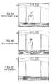
- a predetermined fixed methodFor example, in a technique disclosed in Japanese Laid-Open Patent Publication No. 03-99952 (literature 1), a plurality of cameras are placed on a car as shown in FIG. 20A . Images of the surroundings of the car taken with the cameras are transformed, to produce an image viewed from top with the car in the center as shown in FIG. 20B , and the resultant image is presented to a display mounted in the car.
- the position of an obstacle in an image taken with a camera placed on a vehicleis computed.
- the imageis transformed according to the computed position of the obstacle, to be displayed on a display.
- the position of an obstacle in an imageis computed using two images taken at slightly different times when the vehicle is moving.
- the imagesare transformed using the computed position of the obstacle, to obtain a synthesized image viewed from side as shown in FIG. 21A .
- the drivercan check a blind spot, of which direct observation is not possible from the driver's seat, with a display, and can easily grasp how the obstacle is apart from the vehicle with an image viewed from top or side. In this way, the driver can drive more safely.
- the obstaclemay possibly be displayed at a wrong position, or the obstacle may not be displayed in a synthesized image.
- the position of an obstacleis computed by extracting the motion of a luminance edge from two images taken at slightly different times. In the actual drive environment, however, there often occur such cases that the computed position includes errors greatly and that the position of an obstacle is undetectable at all. In the case that the computed position includes errors greatly, the obstacle may be displayed at a position farther than the actual position, or the obstacle may not be shown in the synthesized image. This may mislead the driver and thus prevent the driver from driving safely.
- An object of the present inventionis providing a technology that enables presentation of an image showing the situation around a vehicle more naturally in a manner not to mislead the driver than conventionally achieved.
- position information and the reliability indicating how precisely the position information has been computedare computed for a plurality of points in camera images. Based on this reliability, an image synthesis scheme to be adopted is selected as appropriate, for the entire image or partially, between an image synthesis scheme in which the camera images are transformed using the position information and an image synthesis scheme in which the camera images are transformed by a predetermined method without use of the position information. By this selection, if the reliability is high indicating that the position information has been computed correctly, a synthesized image with little distortion produced using the position information is displayed.
- the vehicle surroundings monitoring device of the present inventionis a device for producing a synthesized image showing the situation around a vehicle from images taken with a camera capturing the surroundings of the vehicle and presenting the synthesized image, including: a position computation section for computing position information and reliability of the position information, for a plurality of points in the camera images; an image variable-synthesis section for producing a first synthesized image from the camera images using the position information; an image fixed-synthesis section for producing a second synthesized image from the camera images by a predetermined method without use of the position information; and a synthesis scheme selection section for selecting either one of the first and second synthesized images according to the reliability as the synthesized image to be presented.
- the synthesis scheme selection sectionmay select image parts from the first and second synthesized images according to the reliability, in place of selecting either one of the first and second synthesized images, and produce the synthesized image to be presented from the selected image parts.
- the image production method of the present inventionis a method for producing a synthesized image showing the situation around a vehicle from images taken with a camera capturing the surroundings of the vehicle, including the steps of: (1) computing position information and the reliability of the position information, for a plurality of points in the camera images; (2) comparing the reliability computed in the step (1) with a predetermined reference; (3) producing the synthesized image from the camera images using the position information computed in the step (1) if the reliability is determined higher than the predetermined reference in the step (2); and (4) producing the synthesized image from the camera images by a predetermined method without use of the position information if the reliability is determined lower than the predetermined reference in the step (2).
- a program enabling a computer to execute the image production method of the present inventionis provided.
- FIG. 1is a block diagram showing a configuration of vehicle surroundings monitoring devices of Embodiments 1 and 2 of the present invention.
- FIG. 2Aillustrates an example of placement of cameras in Embodiment 1, and
- FIGS. 2B and 2Care examples of camera images taken in the situation shown in FIG. 2A .
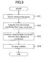
- FIG. 3is a flowchart of the operation of a position computation section.
- FIG. 4is a conceptual view showing the relationship between camera coordinate systems.
- FIG. 5is a conceptual view demonstrating image synthesis using the plane of road surface as the reference.
- FIGS. 6A and 6Bare examples of a first synthesized image produced by an image variable-synthesis section in Embodiment 1.
- FIG. 7is an example of a second synthesized image produced by an image fixed-synthesis section in Embodiment 1.
- FIGS. 8A to 8Care examples of a synthesized image presented in Embodiment 2.
- FIG. 9is a block diagram showing a configuration of vehicle surroundings monitoring devices of Embodiments 3 and 4 of the present invention.
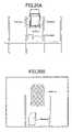
- FIG. 10illustrates an example of placement of cameras and an obstacle sensor in Embodiment 3.
- FIG. 11Aillustrates an example of placement of cameras in Embodiment 4.
- FIGS. 11B and 11Care examples of camera images taken in the situation shown in FIG. 11A .
- FIG. 12Ais an example of a first synthesized image produced by an image variable-synthesis section
- FIG. 12Bis an example of a second synthesized image produced by an image fixed-synthesis section in Embodiment 4.
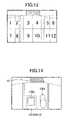
- FIG. 13illustrates an example of region division for partial selection of a synthesized image.
- FIG. 14is an example of a synthesized image produced by a synthesis scheme selection section in Embodiment 4.
- FIG. 15is a block diagram showing a configuration of a vehicle surroundings monitoring device of Embodiment 5 of the present invention.
- FIG. 16is an example of a first synthesized image produced by an image variable-synthesis section in Embodiment 5.
- FIGS. 17A and 17Bare examples of a synthesized image output from a synthesis scheme selection section in Embodiment 5.
- FIG. 18is a block diagram of a vehicle surroundings monitoring device of the present invention, configured using a computer.
- FIG. 19is a flowchart showing a flow of processing followed by the configuration of FIG. 18 .
- FIGS. 20A and 20Bare views showing a conventional technique.
- FIGS. 21A and 21Bare views showing another conventional technique together with its problem.
- FIG. 1is a block diagram of a vehicle surroundings monitoring device of Embodiment 1 of the present invention.
- the vehicle surroundings monitoring device of FIG. 1produces a synthesized image showing the situation around a vehicle from images taken with cameras capturing the surroundings of the vehicle, and presents the synthesized image to a display.
- the vehicle surroundings monitoring deviceincludes: cameras 11 a and 11 b for capturing the surroundings of a vehicle; A/D converters 12 a and 12 b for digitizing an analog video signal obtained from the cameras 11 a and 11 b; and frame memories 13 a and 13 b for temporarily holding the digitized camera images.
- the devicealso includes: a position computation section 14 for computing position information PI and the reliability RL of the position information PI, for a plurality of points in camera images; an image variable-synthesis section 15 for transforming the camera images using the position information PI to produce a first synthesized image SI 1 viewed from a different perspective; an image fixed-synthesis section 16 for transforming the camera images by a predetermined method without use of the position information PI to produce a second synthesized image SI 2 viewed from a different perspective; and a synthesis scheme selection section 17 for selecting either one of the first and second synthesized images SI 1 and SI 2 according to the reliability RL as the synthesized image to be presented.
- the devicefurther includes: a frame memory 18 for temporarily holding the synthesized image to be presented; a D/A converter 19 for converting the digital image data held in the frame memory 18 to an analog video signal; and a display 20 for displaying the analog video signal.
- FIG. 2Ashows an example of placement of cameras in this embodiment
- FIGS. 2B and 2Care examples of camera images.
- two cameras(camera 1 and camera 2 , corresponding to the cameras 11 a and 11 b in FIG. 1 ) are placed on the rear of a vehicle 1 so as to capture the scene behind the vehicle.
- OBdenotes an obstacle
- WLdenotes white lines.
- FIGS. 2B and 2Care examples of camera images taken with the camera 1 and the camera 2 , respectively. As is found from FIGS. 2B and 2C , the coverage of the camera 1 overlaps the coverage of the camera 2 .
- the camerasmay also be placed somewhere other than on the vehicle, such as in a parking lot and on a facility along a road. It is assumed that the display 20 is placed at a position in the vehicle 1 permitting easy view by the driver. Naturally, the display 20 may be placed somewhere other than in the vehicle.
- the position computation section 14computes position information of each of a plurality of points in the camera images and the reliability of the position information, by using three-dimensional position detection with so-called binocular stereo.
- FIG. 3is a flowchart of the operation of the position computation section 14 .
- the position computation section 14reads camera image data from the frame memories 13 a and 13 b, specifies corresponding points from the two camera images (first and second camera images), and computes the coordinates of the corresponding points (S 11 ).
- image data of the first camera imageis sequentially read from the frame memory 13 a, and the amount of change in intensity in a small region around each pixels are computed.
- a predetermined number of pixels (u 1 i , v 1 i ) are in the computed intensity change amountare selected from all pixels from largest to smaller.
- pixels on the boundary of an object and the likeare more likely to be selected.
- a pixel (u 1 , v 1 ) corresponding to an edge of the obstacle OBis selected.
- the following relational expressionis established among the image coordinates (u 1 , v 1 ) and (u 2 , v 2 ) of a corresponding point, the coordinates (x 1 , y 1 , z 1 ) of this point in the viewpoint coordinate system of the camera 1 , the inter-camera positional relationship M 12 and the camera parameters f 1 and f 2 .
- the camera parameters f 1 and f 2are respectively obtained by multiplying the focal distance of the camera by the transformation coefficient for the pixel size and the image coordinates.
- the three-dimensional coordinates (x 1 , y 1 , z 1 ) of the corresponding pointcan be obtained by substituting the previously measured parameters M 12 , f 1 and f 2 and the computed image coordinates (u 1 , v 1 ) and (u 2 , v 2 ) of the corresponding point into Expression 2. Because Expression 2 includes four independent linear equations for three unknowns and the image coordinates (u 1 , v 1 ) and (u 2 , v 2 ) of the corresponding point computed from the images probably includes errors, the three-dimensional coordinates (x 1 , y 1 , z 1 ) are computed by the method of least squares. This can reduce influence of the errors.
- the position computation section 14inversely computes image coordinates (u 1 ′, v 1 ′) and (u 2 ′, v 2 ′) in the first and second camera images from the three-dimensional coordinates (x 1 , y 1 , z 1 ) obtained by the method of least squares (S 13 ). That is, the three-dimensional coordinates (x 1 , y 1 , z 1 ) and the parameters M 12 , f 1 and f 2 are substituted into Expression 2 to newly obtain image coordinates in the first and second camera images.
- the inversely-computed image coordinates (u 1 ′, v 1 ′) and (u 2 ′, v 2 ′)should match with the original image coordinates (u 1 , v 1 ) and (u 2 , v 2 ) if there is no measurement error. In general, however, there is a measurement error, and thus these values do not match with each other.
- the reliability ris determined by the following expression (S 14 ).
- the reliability ris 1 when no measurement error is included in the coordinates of the corresponding point, and is closer to 0 with increase of the measurement error.
- the reliability rrepresents the degree at which the computed position information (u 1 , v 1 , u 2 , v 2 , x 1 , y 1 , z 1 ) of the corresponding point includes errors, and thus serves as an indicator of whether or not the position information is reliable.
- the image variable-synthesis section 15reads the data of the first and second camera images from the frame memories 13 a and 13 b, and produces a first synthesized image SI 1 using the position information PI of the corresponding points computed by the position computation section 14 .
- a synthesis camera placed as shown in FIG. 4is assumed to perform image synthesis by texture mapping using previously given position M 10 and a parameter f 0 of the synthesis camera.
- the texture mappinga technique of synthesizing an image viewed from an arbitrary viewpoint using image data and three-dimensional coordinates of points in an image, is widely known in the field of computer graphics. Detailed description of this technique is therefore omitted here.
- the technique used for the image synthesis by the image variable-synthesis section 15is not limited to the texture mapping.
- Image synthesis reflecting the position informationsuch as a technique in which a given color and/or shape representing an obstacle is superimposed on a synthesized image at a position indicated by the position information, for example, may be adopted.
- the image fixed-synthesis section 16reads data of the first and second camera images from the frame memories 13 a and 13 b, and produces a second synthesized image SI 2 by a predetermined method without use of the position information PI of the corresponding points computed by the position computation section 14 .
- image synthesisis performed using the plane of road surface as the reference as shown in FIG. 5 . That is, if it is assumed that both the cameras 1 and 2 are capturing the plane of road surface, the image coordinates in the camera 1 or 2 corresponding to certain image coordinates in the synthesis camera can be computed as long as the positions of the cameras 1 and 2 and the synthesis camera with respect to the road surface and respective camera parameters are given.
- the image fixed-synthesis section 16stores therein a reference table containing a value ci indicating the camera concerned and image coordinates (ui, vi) in the camera that have been computed in advance for all image coordinates (uoi, voi) in the synthesis camera. According to the reference table, the image fixed-synthesis section 16 reads image data (ci, ui, vi) corresponding to the respective coordinates (uoi, voi) in the synthesized image sequentially from the frame memories 13 a and 13 b, to thereby produce a synthesized image.
- This type of image synthesis using the plane of road surface as the referenceis disclosed in International Publication No. WO 00/07373, for example. Detailed description thereof is therefore omitted here.
- FIGS. 6A and 6Bare examples of the first synthesized image SI 1 produced by the image variable-synthesis section 15 in the situation shown in FIG. 2A .
- FIG. 6Ashows the case that the position information PI of corresponding points has been computed correctly by the position computation section 14
- FIG. 6Bshows the case that the position information PI includes errors greatly.
- 1 Arepresents the vehicle 1 .
- the first synthesized image SI 1obtained by changing the viewpoint while maintaining the three-dimensional position of the object in the original camera images, has a feature that the distance from the obstacle OB can be easily grasped, compared with the camera images shown in FIGS. 2B and 2C .
- the first synthesized image SI 1has another feature that the position and shape of the obstacle OB are not precise if the position information PI includes errors greatly.
- FIG. 7is an example of the second synthesized image SI 2 produced by the image fixed-synthesis section 16 in the situation shown in FIG. 2A .
- the positional relationship between the vehicle and a region at which the obstacle OB contacts the road surfaceis precise, but a region having a height with respect to the plane of road surface is shown in a distorted, unnatural shape.
- the synthesis scheme selection section 17selects either one of the first and second synthesized images SI 1 and SI 2 according to the reliability RL computed by the position computation section 14 as the synthesized image to be presented, and outputs the selected synthesized image.
- the first synthesized image SI 1 produced by the image variable-synthesis section 15is selected when the reliability RL is determined higher than a predetermined reference, that is, when the position information PI does not include errors so greatly.
- the second synthesized image SI 2 produced by the image fixed-synthesis section 16is selected when the reliability RL is determined lower than a predetermined reference, that is, when the position information PI includes errors greatly.
- the reliability RLis compared with a predetermined reference in the following manner. First, reliabilities ri of n corresponding points computed by the position computation section 14 are respectively compared with a predetermined threshold rth, and the number m of corresponding points having a reliability equal to or higher than the predetermined threshold rth is counted. The ratio m/n of the number m of corresponding points equal to or higher than the threshold rth to the total number n is compared with a predetermined threshold mth. If the ratio m/n is greater than the threshold mth, the reliability RL is determined higher than the predetermined reference, and thus the first synthesized image SI 1 produced by the image variable-synthesis section 15 is selected.
- the reliability RLis determined lower than the predetermined reference, and thus the second synthesized image SI 2 produced by the image fixed-synthesis section 16 is selected.
- the comparison of the reliability with the predetermined referenceis not limited to the way described above. For example, the number of corresponding points having reliabilities ri higher than the threshold value rth may be compared with a threshold.
- the cameras 11 a and 11 btake images at the respective fixed periods.
- the position computation section 14 , the image variable-synthesis section 15 , the image fixed-synthesis section 16 and the synthesis scheme selection section 17execute the operation described above repeatedly every time a camera image is obtained. In this way, a synthesized image corresponding to the temporally changing situation around the vehicle is displayed on the display 20 .
- the drivertakes a look at the synthesized image displayed on the display 20 and drives by referring to the synthesized image.
- the image variable-synthesis section 15produces the synthesized image of FIG. 6A when the position information PI has been computed correctly by the position computation section 14 or the synthesized image of FIG. 6B when the position information PI has not been computed correctly, while the image fixed-synthesis section 16 produces the synthesized image of FIG. 7 .
- the image of FIG. 6Ais natural with no distortion of the obstacle OB compared with the image of FIG. 7 .
- the image of FIG. 6Bmay cause the driver to misjudge the position of the obstacle OB with high possibility. In this case, therefore, the image of FIG. 7 is more preferable.
- the synthesis scheme selection section 17determines whether or not the position information PI has been computed correctly using the reliability RL, selects the synthesized image of FIG. 6A produced by the image variable-synthesis section 15 when the position information PI has been computed correctly, or selects the synthesized image of FIG. 7 produced by the image fixed-synthesis section 16 when the position information PI includes errors greatly, and outputs the selected synthesized image.
- a natural image safer for the drivercan be presented.
- the position computation sectioncomputes the position information of an object in an image and the reliability of the position information.
- the image variable-synthesis sectionproduces the first synthesized image by transforming camera images using the position information
- the image fixed-synthesis sectionproduces the second synthesized image by transforming camera images following a predetermined procedure without use of the position information.
- the first synthesized imageis selected when it is determined from the reliability of the position information that the position information has been computed correctly.
- the second synthesized imageis selected when it is determined that the position information has the possibility of including errors greatly.
- the resultant synthesized imageis free from the problems that an obstacle is displayed at a wrong position and that an actually existing obstacle is not displayed.
- a synthesized image with little distortioncan be displayed in some situations. In this way, a more natural image safer for the driver can be presented.
- the image variable-synthesis section 15 and the image fixed-synthesis section 16should preferably synthesize images so that the first and second synthesized images match with each other in the position of the road surface. This prevents an occurrence that the resultant synthesized image is hard to look at when the image synthesis scheme is frequently switched, and thus allows the driver to easily grasp the situation around the vehicle.
- the reliability RL of the position informationgreatly changes every time the processing is repeated in some situations of taking images, causing frequent switching between the first synthesized image and the second synthesized image.
- the image variable-synthesis section 15 and the image fixed-synthesis section 16may be set in advance to be common in the position and internal parameters of the synthesis camera in image synthesis. By this setting, it is possible to produce synthesized images with the road surface located at substantially the same position as shown in FIGS. 6A , 6 B and 7 . As a result, the resultant synthesized image will not be hard to look at even when it is frequently switched.
- the image synthesis schemewas selected according to the reliability of the position information.
- hysteresismay be given to the threshold for the selection, so that frequent switching of the image synthesis scheme can be suppressed in an event that the reliability minutely fluctuates at a rapid period, for example.
- Frequent switching of the image synthesis schemecan also be suppressed by imposing a restriction that the switching is made only after the lapse of a predetermined time. By this suppression, the resultant synthesized image becomes easier to look at, and thus the driver can more easily grasp the situation around the vehicle.
- the image synthesis schemewas selected according to the reliability of the position information.
- the position informationitself may additionally be used for selection of the image synthesis scheme.
- the synthesis scheme selection section 17may extract points belonging to a region used for the image synthesis by the image variable-synthesis section 15 and the image fixed-synthesis section 16 by referring to the three-dimensional positions and image coordinates of respective corresponding points included in the position information.
- the reliability of the extracted pointsmay be used for the selection of the synthesized image. Specifically, for example, if the number of extracted points is equal or more than a predetermined value, the image synthesis scheme may be selected using the reliability of the extracted points following the procedure described above.
- the second synthesized image SI 2 produced by the image fixed-synthesis section 16may be selected.
- the reliability of corresponding points that do not belong to the region used for the image synthesisis no more considered in the selection of the image synthesis scheme.
- a more suitable synthesized imagecan be presented.
- the cameraswere placed so as to capture the scene behind the vehicle and be different in horizontal position from each other as shown in FIG. 2A .
- the camera coverage and the camera mount positionare not specifically limited. As long as the cameras are placed so that the camera coverages overlap each other, the processing described in this embodiment can be performed for the overlapping region.
- the reliability of the position information of a corresponding pointwas calculated from Expression 3 based on the image coordinates.
- the computation of the reliabilityis not limited to this, but any reference value may be used-as long as it can serve as a scale indicating the magnitude of errors included in the position information of a corresponding point and the possibility of occurrence of errors.
- the image variable-synthesis section 15performed image synthesis using position information of n corresponding points computed by the position computation section 14 .
- position information of only points having a reliability equal to or greater than a predetermined threshold among the n corresponding pointsmay be selected and used. This selection eliminates position information low in reliability, and thus synthesis errors can be reduced in the resultant synthesized image.
- a single image variable-synthesis section 15 and a single image fixed-synthesis section 16were provided.
- the number of image synthesis sectionsis not limited to this.
- a plurality of image variable-synthesis sections and/or a plurality of image fixed-synthesis sectionsmay be provided, and the synthesis scheme selection section 17 may select one of synthesized images produced by these image synthesis sections according to the reliability of the position information.
- the position computation section 14adopted the binocular stereo system in which images taken with two cameras simultaneously were used for computation of a position.
- a so-called motion stereo systemmay be adopted in which two temporally sequential camera images are used for computation of a position. In this case, also, the effect described in this embodiment is obtained.
- a vehicle surroundings monitoring device of Embodiment 2has the same configuration as that of Embodiment 1 shown in FIG. 1 , except that a synthesis scheme selection section 17 A in this embodiment superimposes on a synthesized image an indication according to a feature of the synthesized image.
- the position information PIitself is used in combination with the reliability RL of the position information for the selection of a synthesized image.
- the synthesis scheme selection section 17 Aoperates as follows.
- the synthesis scheme selection section 17 Aextracts points belonging to an obstacle that is likely to appear in a synthesized image from n corresponding points specified by the position computation section 14 .
- the synthesis scheme selection section 17 Aextracts points that are apart from the road surface by a predetermined distance and belong to a region used for image synthesis, based on three-dimensional position coordinates and image coordinates included in the position information PI.
- the synthesis scheme selection section 17 Aperforms the processing described in Embodiment 1 using the reliability of the extracted points, and selects the first synthesized image SI 1 produced by the image variable-synthesis section 15 if the reliability is higher than a predetermined reference. In this case, determining that the position of the obstacle OB has been detected precisely, the synthesis scheme selection section 17 A superimposes a massage “The position of an obstacle has been detected”, for example, on the synthesized image as shown in FIG. 8A . If the reliability is lower than the predetermined reference, the synthesis scheme selection section 17 A selects the second synthesized image SI 2 produced by the image fixed-synthesis section 16 .
- the synthesis scheme selection section 17 Asuperimposes a massage “Failed to compute the position; this image has distortion”, for example, on the synthesized image as shown in FIG. 8B .
- the synthesis scheme selection section 17 Aselects the second synthesized image SI 2 produced by the image fixed-synthesis section 16 . In this case, determining that no obstacle has been detected around the vehicle, the synthesis scheme selection section 17 A superimposes a massage “No obstacle detected”, for example, on the synthesized image as shown in FIG. 8C .
- the shape of an obstaclemay be distorted in the second synthesized image SI 2 produced by the image fixed-synthesis section 16 as shown in FIG. 7 .
- the usercannot judge whether the obstacle has a rectangular solid and image includes a distortion, or whether the image includes no distortion and the obstacle has a squashed rectangular solid.
- the usermay possibly misunderstand the shape of the obstacle. For example, the driver may mistakenly judge that the obstacle shown in FIG. 7 is short enough to be overridden. This raises a problem in safety.
- an indication according to a feature of the selected synthesized imageis superimposed on the image. Therefore, the user can easily recognize that the synthesized image includes a distortion, for example. In this way, the user is prevented from misjudging the situation around the vehicle due to the nature of the synthesized image, and as a result, safer drive is realized.
- FIG. 9is a block diagram of a vehicle surroundings monitoring device of Embodiment 3 of the present invention.
- the same components as those in FIG. 1are denoted by the same reference numerals, and the description thereof is omitted here.
- the configuration of FIG. 9is different from that of FIG. 1 in that the vehicle is provided with an obstacle sensor 31 for detecting an obstacle around the vehicle and outputting distance information DI, and that a synthesis scheme selection section 17 B selects a synthesized image by additional use of the distance information DI sent from the obstacle sensor 31 .
- the obstacle sensor 31measures the distance from a neighboring obstacle at a fixed period, and outputs distance information DI if an obstacle exists within the range of a predetermined distance.
- the obstacle sensor 31is an ultrasonic sensor in which the distance from an object is computed from the time required for ultrasound emitted to return after being reflected by the obstacle.
- FIG. 10shows an example of placement of cameras and an obstacle sensor in this embodiment.
- the obstacle sensor 31is placed between the camera 1 and the camera 2 .
- the positional relationship among the obstacle sensor 31 , the camera 1 and the camera 2has been determined in advance.
- the synthesis scheme selection section 17 Bcompares the reliability RL of the position information with a predetermined reference and selects a synthesized image according to the comparison result, as in Embodiment 1.
- a predetermined error threshold dththat is, whether or not there is a corresponding point having a distance di substantially equal to the distance information DI.
- the synthesis scheme selection section 17 Bcompares the reliability RL of the position information with a predetermined reference and selects a synthesized image according to the comparison result, as in Embodiment 1. If there is no corresponding point having a distance di substantially equal to the distance information DI, that is, if it is determined that the accuracy of the position information PI on the obstacle OB is not sufficient, the synthesis scheme selection section 17 B does not perform selection according to the reliability RL, but simply selects the second synthesized image produced by the image fixed-synthesis section 16 .
- the obstacle sensor 31can detect an obstacle existing in a short distance comparatively reliably.
- the obstacle sensor 31outputs distance information DI, an obstacle actually exists at the position indicated by the distance information DI with high possibility.
- the position informationmay include errors greatly, or a corresponding point itself on an obstacle may fail to be computed in the cases that the obstacle has a uniform luminance or color tone and that the obstacle is less distinguished from the background, in particular.
- the problem that the position information includes errorscan be solved to some extent by selecting an image synthesis scheme based on the reliability of the position information. However, if a corresponding point itself on an obstacle fails to be computed, this failure will not be recognized from evaluation using the reliability.
- the synthesis scheme selection section 17 Bdetermines whether or not there is a corresponding point having a distance di substantially equal to the distance information DI. If there is no corresponding point, the position information includes errors greatly, or a corresponding point on the obstacle fails to be computed, with high possibility. In other words, it is considered that the accuracy of the position information PI computed by the position computation section 14 is not sufficient for the obstacle OB detected by the obstacle sensor 31 . In such a case, the second synthesized image SI 2 produced by the image fixed-synthesis section 16 is selected, to ensure display of a synthesized image including no error in the position of the obstacle.
- the image synthesis schemeis selected using the reliability as in Embodiment 1. In this way, the problems that the obstacle is displayed at a wrong position and that an actually existing obstacle is not displayed are avoided. In addition, a synthesized image with little distortion can be displayed in some situations. Thus, a more natural image safer for the driver can be presented.
- a vehicle surroundings monitoring device of Embodiment 4has the same configuration as that of Embodiment 3 shown in FIG. 9 , except that a synthesis scheme selection section 17 C in this embodiment does not select either one of the first and second synthesized images SI 1 and SI 2 produced by the image variable-synthesis section 15 and the image fixed-synthesis section 16 , but selects image parts from the first and second synthesized images SI 1 and SI 2 according to the reliability RL, to produce a synthesized image to be presented.
- FIG. 11Ashows an example of placement of cameras in this embodiment
- FIGS. 11B and 11Care examples of camera images. Assume that two obstacles OBa and OBb existing behind the vehicle 1 are captured by the cameras.
- the position computation section 14computes position information of a plurality of points in the camera images of FIGS. 11B and 11C and the reliability of the position information.
- the position information computed by the position computation section 14 in a region of an image including one objectis different in the possibility of including errors and the magnitude of errors from the position information in a region including another object.
- the position information of a point in a region including the obstacle OBais small in error
- the position information of a point in a region including the obstacle OBbis large in error.
- the position information of a point in a region including the obstacle OBais high in reliability
- the position information of a point in a region including the obstacle OBbis low in reliability.
- FIG. 12Ais an example of the first synthesized image SI 1 produced by the image variable-synthesis section 15
- FIG. 12Bis an example of the second synthesized image SI 2 produced by the image fixed-synthesis section 16 .
- the obstacle OBais displayed at a correct position because the position information in the region including the obstacle OBa is high in reliability.
- the obstacle OBbis displayed at a wrong position because the position information in the region including the obstacle OBb is low in reliability and thus includes errors greatly.
- the synthesis scheme selection section 17 Cselects a synthesized image separately for a plurality of divided regions as shown in FIG. 13 (12 regions in FIG. 13 ). Specifically, the synthesis scheme selection section 17 C computes positions of points on a synthesized image using the position information of the respective points computed by the position computation section 14 and the synthesis parameters of the image variable-synthesis section 15 and the image fixed-synthesis section 16 . For each of the regions shown in FIG. 13 , the synthesis scheme selection section 17 C selects the first synthesized image SI 1 produced by the image variable-synthesis section 15 when the reliability is equal to or higher than a predetermined threshold, or selects the second synthesized image SI 2 produced by the image fixed-synthesis section 16 when the reliability is lower than the predetermined threshold.
- FIG. 14is an example of an image output from the synthesis scheme selection section 17 C.
- the first synthesized image SI 1has been selected for the region including the obstacle OBa (region 9 in FIG. 13 ) because the reliability of the position information is high, while the second synthesized image SI 2 has been selected for the other regions.
- the obstacle OBais displayed at a correct position with little distortion but the obstacle OBb is displaced.
- regions at which the obstacles OBa and OBb contact the road surfaceare displayed at correct positions but regions having heights with respect to the plane of the road surface are distorted.
- both the obstacles OBa and OBbare displayed nicely, that is, the obstacles OBa and OBb are at correct positions and the obstacle OBa is with little distortion, and thus a more suitable synthesized image is presented.
- the first and second synthesized images SI 1 and SI 2are partially selected according to the reliability of position information, to produce a synthesized image. This enables display of a synthesized image that shows the positions of obstacles more correctly and has less distortion.
- a synthesized imagewas selected for each of divided regions as shown in FIG. 13 .
- the number of regions, the locations of division, the size of the regions and the likeare not limited to those described above.
- the regions for partial selection of a synthesized imagemay not be determined in advance, but may be determined dynamically. For example, after the positions of points on a synthesized image are computed from the position information of the points and the parameters of image synthesis, the density of the points and the average of the reliability are computed for each of unit rectangular regions of a predetermined size. The first synthesized image SI 1 is selected if these values are greater than predetermined thresholds, and the second synthesized image SI 2 is selected if they are equal to or less than the thresholds.
- a region high in the density of points and reliabilityshould be a region in which the position of an obstacle has been computed correctly. Therefore, by selecting such a region dynamically, a synthesized image with less distortion can be produced.
- the position information PI and the distance information DImay be additionally used for the image selection, as described in the above embodiment.
- FIG. 15is a block diagram of a vehicle surroundings monitoring device of Embodiment 5 of the present invention.
- the configuration of FIG. 15is different from that of FIG. 9 in that the vehicle has a moving direction detection means 32 for detecting the direction of moving of the vehicle, and that a synthesis scheme selection section 17 D selects a synthesized image by additional use of moving direction information sent from the moving direction detection means 32 .
- the moving direction detection means 32may be essentially composed of a car speed sensor, a turning angle sensor and a means for computing the moving direction of the vehicle from the outputs of the car speed sensor and the turning angle sensor.
- the moving direction detection means having such a configurationis already widely known, and thus detailed description thereof is omitted here.
- the reliability RL of the position information PI computed by the position computation section 14is high in the region including the obstacle OBa, but is lower in the region including the obstacle OBb compared with that in the region including the obstacle OBa.
- the first synthesized image SI 1 produced by the image variable-synthesis section 15is as shown in FIG. 16 , in which, while the obstacle OBa is displayed at a correct position because the position information is small in error, the obstacle OBb is displaced a little because the position information includes errors largely.
- the synthesis scheme selection section 17 Dspecifies a point corresponding to a region of the image located in the moving direction of the vehicle among the plurality of points specified by the position computation section 14 , and selects a synthesized image according to the reliability of the specified point.
- the synthesis scheme selection section 17 Dselects a synthesized image based on the reliability of a point belonging to the region including the obstacle OBa. Contrarily, when the vehicle moves backward to the right, that is, moves toward the obstacle OBb, the synthesis scheme selection section 17 D selects a synthesized image based on the reliability of a point belonging to the region including the obstacle OBb.
- FIG. 17Ais an example of a synthesized image output by the synthesis scheme selection section 17 D when the vehicle moves backward to the left, in which the first synthesized image SI 1 produced by the image variable-synthesis section 15 has been selected because the reliability of a point in the region including the obstacle OBa located in the moving direction of the vehicle is high.
- FIG. 17Bis an example of a synthesized image output by the synthesis scheme selection section 17 D when the vehicle moves backward to the right, in which the second synthesized image SI 2 produced by the image fixed-synthesis section 16 has been selected because the reliability of a point in the region including the obstacle OBb located in the moving direction of the vehicle is low.
- An image of a region located in the moving direction of the vehicleis very important during driving. Therefore, an obstacle existing in a region located in the moving direction of the vehicle should desirably be displayed at a correct position. However, no serious problem will occur if an obstacle existing outside such a region is displayed at a more or less displaced position. The driver may be affected more greatly by a strange feeling against a distorted shape than by a small positional displacement in some cases. In such cases, a more suitable synthesized image can be presented in this embodiment.
- the moving direction of the vehicleis additionally used for the selection of a synthesized image, in which the reliability of a point in a region located in the moving direction of the vehicle is used. Therefore, it is possible to present such a synthesized image that an obstacle will not be shown at a wrong position in a region located in the moving direction of the vehicle and little distortion is included in the other region.
- hysteresismay be given to the threshold used as the reference for selection of a synthesized image, and the width of the hysteresis may be changed with the moving speed of the vehicle. Specifically, the width of the hysteresis may be made greater with increase of the moving speed of the vehicle. In general, as the moving speed of the vehicle is higher, the change of the image with time is greater, and thus the change of the reliability with time is greater. Therefore, by increasing the width of the hysteresis with increase of the moving speed, frequent switching of the synthesized image can be suppressed, and thus the driver will find less difficulty in grasping the situation around the vehicle.
- the cameras, the display, the AID converters, the D/A converter, the frame memories, the obstacle sensor and the moving direction detection meansare not necessarily requisite components of the vehicle surroundings monitoring device of the present invention.
- the processing means according to the present inventionthat is, the position computation section, the image variable-synthesis section, the image fixed-synthesis section and the synthesis scheme selection section were respectively implemented by hardware.
- these meansmay be implemented by software.
- the vehicle surroundings monitoring device of the present inventionis configured of a computer including a CPU 41 , a ROM 42 and a RAM 43 as shown in FIG. 18 , for example.
- the processing meanssuch as the position computation section, the image variable-synthesis section, the image fixed-synthesis section and the synthesis scheme selection section are implemented by executing a program stored in the ROM 42 or the RAM 43 with the CPU 41 .
- FIG. 19is a flowchart showing an example of flow of processing followed by the configuration of FIG. 18 , which corresponds to the image production method and the image production program according to the present invention.
- camera imagesare received from the frame memories 13 a and 13 b (S 21 ).
- Position information and the reliability thereofare determined for a plurality of points from the received camera images as in the operation of the position computation section 14 described above (S 22 ).
- the reliabilityis compared with a predetermined reference as described in Embodiment 1 (S 23 ). If the reliability is higher than the predetermined reference (Yes in S 24 ), a synthesized image is produced from the camera images using the position information, as in the operation of the image variable-synthesis section 15 (S 25 ).
- a synthesized imageis produced from the camera images by a predetermined method without use of the position information, as in the operation of the image fixed-synthesis section 16 (S 26 ).
- the produced synthesized imageis then output to the frame memory 18 (S 27 ).
- a synthesized imagewas selectively produced according to the reliability.
- two types of synthesized imagesmay be produced first, and then either one of them may be selected according to the reliability.
- the synthesis scheme selection section 17may selectively put either one of the image variable-synthesis section 15 and the image fixed-synthesis section 16 into operation according to the reliability.
- the present inventionmay be applied, not only to monitoring of the surroundings of a vehicle, but also to robots, for example.
- a remote-controllable mobile robotmay be provided with a camera and the monitoring device of the present invention.
- a synthesized image showing the situation around the robotmay be displayed on a remote display to enable monitoring by the user of the robot.
- the effect described in the embodiments of the present inventioncan be obtained.
- a synthesized image with little distortionis displayed when the position information has been computed correctly.
- the position informationincludes errors greatly, a synthesized image free from an obstacle being displayed at a wrong position or an obstacle disappearing is displayed. Therefore, a more natural and safer image can be presented.
Landscapes
- Engineering & Computer Science (AREA)
- Physics & Mathematics (AREA)
- General Physics & Mathematics (AREA)
- Computer Vision & Pattern Recognition (AREA)
- Theoretical Computer Science (AREA)
- Electromagnetism (AREA)
- Radar, Positioning & Navigation (AREA)
- Remote Sensing (AREA)
- Multimedia (AREA)
- Signal Processing (AREA)
- Image Processing (AREA)
- Closed-Circuit Television Systems (AREA)
Abstract
Description
Claims (15)
Applications Claiming Priority (2)
| Application Number | Priority Date | Filing Date | Title |
|---|---|---|---|
| JP2002-159085 | 2002-05-31 | ||
| JP2002159085 | 2002-05-31 |
Publications (2)
| Publication Number | Publication Date |
|---|---|
| US20030222983A1 US20030222983A1 (en) | 2003-12-04 |
| US7110021B2true US7110021B2 (en) | 2006-09-19 |
Family
ID=29417250
Family Applications (1)
| Application Number | Title | Priority Date | Filing Date |
|---|---|---|---|
| US10/447,523Expired - LifetimeUS7110021B2 (en) | 2002-05-31 | 2003-05-29 | Vehicle surroundings monitoring device, and image production method/program |
Country Status (2)
| Country | Link |
|---|---|
| US (1) | US7110021B2 (en) |
| EP (1) | EP1367408B1 (en) |
Cited By (57)
| Publication number | Priority date | Publication date | Assignee | Title |
|---|---|---|---|---|
| US20050163343A1 (en)* | 2002-12-18 | 2005-07-28 | Aisin Seiki Kabushiki Kaisha | Movable body circumstance monitoring apparatus |
| US20050249379A1 (en)* | 2004-04-23 | 2005-11-10 | Autonetworks Technologies, Ltd. | Vehicle periphery viewing apparatus |
| US20060072788A1 (en)* | 2004-09-28 | 2006-04-06 | Aisin Seiki Kabushiki Kaisha | Monitoring system for monitoring surroundings of vehicle |
| US20060197761A1 (en)* | 2005-03-03 | 2006-09-07 | Nissan Motor Co., Ltd. | Image processor and image processing method for a vehicle |
| US20060291698A1 (en)* | 2005-06-24 | 2006-12-28 | Nissan Motor Co., Ltd. | Image generation device and method for vehicle |
| US20070177011A1 (en)* | 2004-03-05 | 2007-08-02 | Lewin Andrew C | Movement control system |
| US20080165250A1 (en)* | 2007-01-08 | 2008-07-10 | Jeff Kirk Ekdahl | Vehicle security surveillance system |
| US20090259401A1 (en)* | 2008-04-15 | 2009-10-15 | Caterpillar Inc. | Vehicle collision avoidance system |
| US20090259399A1 (en)* | 2008-04-15 | 2009-10-15 | Caterpillar Inc. | Obstacle detection method and system |
| US20090259400A1 (en)* | 2008-04-15 | 2009-10-15 | Caterpillar Inc. | Vehicle collision avoidance system |
| US20100164706A1 (en)* | 2008-12-30 | 2010-07-01 | Industrial Technology Research Institute | System and method for detecting surrounding environment |
| US20100238288A1 (en)* | 2006-04-04 | 2010-09-23 | Mark A Klaerner | Method and apparatus for protecting troops |
| US20110128138A1 (en)* | 2009-11-30 | 2011-06-02 | Fujitsu Ten Limited | On-vehicle device and recognition support system |
| US8019505B2 (en) | 2003-10-14 | 2011-09-13 | Donnelly Corporation | Vehicle information display |
| US8047667B2 (en) | 2002-06-06 | 2011-11-01 | Donnelly Corporation | Vehicular interior rearview mirror system |
| US8100568B2 (en) | 1997-08-25 | 2012-01-24 | Donnelly Corporation | Interior rearview mirror system for a vehicle |
| US8121787B2 (en) | 2000-03-02 | 2012-02-21 | Donnelly Corporation | Vehicular video mirror system |
| US8134117B2 (en) | 1998-01-07 | 2012-03-13 | Donnelly Corporation | Vehicular having a camera, a rain sensor and a single-ball interior electrochromic mirror assembly attached at an attachment element |
| US8162493B2 (en) | 1999-11-24 | 2012-04-24 | Donnelly Corporation | Interior rearview mirror assembly for vehicle |
| US8194132B2 (en) | 2006-01-20 | 2012-06-05 | Old World Industries, Llc | System for monitoring an area adjacent a vehicle |
| US8282253B2 (en) | 2004-11-22 | 2012-10-09 | Donnelly Corporation | Mirror reflective element sub-assembly for exterior rearview mirror of a vehicle |
| US8288711B2 (en) | 1998-01-07 | 2012-10-16 | Donnelly Corporation | Interior rearview mirror system with forwardly-viewing camera and a control |
| US8304711B2 (en) | 2002-05-03 | 2012-11-06 | Donnelly Corporation | Vehicle rearview mirror system |
| US8325028B2 (en) | 1998-01-07 | 2012-12-04 | Donnelly Corporation | Interior rearview mirror system |
| US8379289B2 (en) | 2003-10-02 | 2013-02-19 | Donnelly Corporation | Rearview mirror assembly for vehicle |
| US8400704B2 (en) | 2002-09-20 | 2013-03-19 | Donnelly Corporation | Interior rearview mirror system for a vehicle |
| US8427288B2 (en) | 2000-03-02 | 2013-04-23 | Donnelly Corporation | Rear vision system for a vehicle |
| US20130103259A1 (en)* | 2011-10-20 | 2013-04-25 | GM Global Technology Operations LLC | Vehicle suspension system and method of using the same |
| US8465163B2 (en) | 2002-06-06 | 2013-06-18 | Donnelly Corporation | Interior rearview mirror system |
| US8503062B2 (en) | 2005-05-16 | 2013-08-06 | Donnelly Corporation | Rearview mirror element assembly for vehicle |
| US8508383B2 (en) | 2008-03-31 | 2013-08-13 | Magna Mirrors of America, Inc | Interior rearview mirror system |
| US8559093B2 (en) | 1995-04-27 | 2013-10-15 | Donnelly Corporation | Electrochromic mirror reflective element for vehicular rearview mirror assembly |
| US8593521B2 (en) | 2004-04-15 | 2013-11-26 | Magna Electronics Inc. | Imaging system for vehicle |
| US8599001B2 (en) | 1993-02-26 | 2013-12-03 | Magna Electronics Inc. | Vehicular vision system |
| US8610992B2 (en) | 1997-08-25 | 2013-12-17 | Donnelly Corporation | Variable transmission window |
| US8637801B2 (en) | 1996-03-25 | 2014-01-28 | Magna Electronics Inc. | Driver assistance system for a vehicle |
| US8636393B2 (en) | 2006-08-11 | 2014-01-28 | Magna Electronics Inc. | Driver assistance system for vehicle |
| US8653959B2 (en) | 2001-01-23 | 2014-02-18 | Donnelly Corporation | Video mirror system for a vehicle |
| US8665079B2 (en) | 2002-05-03 | 2014-03-04 | Magna Electronics Inc. | Vision system for vehicle |
| US8779910B2 (en) | 1997-08-25 | 2014-07-15 | Donnelly Corporation | Interior rearview mirror system |
| US8797627B2 (en) | 2002-09-20 | 2014-08-05 | Donnelly Corporation | Exterior rearview mirror assembly |
| US8842176B2 (en) | 1996-05-22 | 2014-09-23 | Donnelly Corporation | Automatic vehicle exterior light control |
| US8854465B1 (en) | 2007-01-08 | 2014-10-07 | Jason Charles McIntyre | Vehicle security surveillance system and method for surveillance of a vehicle |
| US8884788B2 (en) | 1998-04-08 | 2014-11-11 | Donnelly Corporation | Automotive communication system |
| US8908039B2 (en) | 2000-03-02 | 2014-12-09 | Donnelly Corporation | Vehicular video mirror system |
| US8977008B2 (en) | 2004-09-30 | 2015-03-10 | Donnelly Corporation | Driver assistance system for vehicle |
| TWI490520B (en)* | 2014-05-29 | 2015-07-01 | ||
| US9319637B2 (en) | 2012-03-27 | 2016-04-19 | Magna Electronics Inc. | Vehicle vision system with lens pollution detection |
| US9376061B2 (en) | 1999-11-24 | 2016-06-28 | Donnelly Corporation | Accessory system of a vehicle |
| US9436880B2 (en) | 1999-08-12 | 2016-09-06 | Magna Electronics Inc. | Vehicle vision system |
| US9445057B2 (en) | 2013-02-20 | 2016-09-13 | Magna Electronics Inc. | Vehicle vision system with dirt detection |
| US9598018B2 (en) | 2013-03-15 | 2017-03-21 | Gentex Corporation | Display mirror assembly |
| US9707896B2 (en) | 2012-10-15 | 2017-07-18 | Magna Electronics Inc. | Vehicle camera lens dirt protection via air flow |
| US9809171B2 (en) | 2000-03-02 | 2017-11-07 | Magna Electronics Inc. | Vision system for vehicle |
| US10457209B2 (en) | 2012-02-22 | 2019-10-29 | Magna Electronics Inc. | Vehicle vision system with multi-paned view |
| US10981507B1 (en) | 2019-11-07 | 2021-04-20 | Focused Technology Solutions, Inc. | Interactive safety system for vehicles |
| US20220327687A1 (en)* | 2017-12-25 | 2022-10-13 | Canon Kabushiki Kaisha | Image Processing apparatus, Control Method and Non-Transitory Computer-Readable Recording Medium Therefor |
Families Citing this family (70)
| Publication number | Priority date | Publication date | Assignee | Title |
|---|---|---|---|---|
| US5668663A (en) | 1994-05-05 | 1997-09-16 | Donnelly Corporation | Electrochromic mirrors and devices |
| EP1168248A3 (en)* | 2000-06-30 | 2003-12-10 | Matsushita Electric Industrial Co., Ltd. | Rendering device |
| US7255451B2 (en) | 2002-09-20 | 2007-08-14 | Donnelly Corporation | Electro-optic mirror cell |
| WO2004103772A2 (en) | 2003-05-19 | 2004-12-02 | Donnelly Corporation | Mirror assembly for vehicle |
| US7653486B2 (en)* | 2004-02-20 | 2010-01-26 | Sharp Kabushiki Kaisha | Surroundings exhibiting system and surroundings exhibiting method |
| US7298247B2 (en)* | 2004-04-02 | 2007-11-20 | Denso Corporation | Vehicle periphery monitoring system |
| JP4624059B2 (en)* | 2004-10-06 | 2011-02-02 | パナソニック株式会社 | Monitoring device |
| US8154599B2 (en)* | 2005-07-29 | 2012-04-10 | Panasonic Corporation | Imaging region adjustment device |
| JP4810953B2 (en)* | 2005-10-07 | 2011-11-09 | 日産自動車株式会社 | Blind spot image display device for vehicles |
| JP4707109B2 (en)* | 2006-03-02 | 2011-06-22 | アルパイン株式会社 | Multi-camera image processing method and apparatus |
| CN101401024B (en) | 2006-03-09 | 2016-03-16 | 金泰克斯公司 | Comprise the vehicle rearview assembly of high intensity display |
| JP4879031B2 (en)* | 2007-01-11 | 2012-02-15 | 三洋電機株式会社 | Driving support system, image processing apparatus, and deviation detection method |
| DE102008060684B4 (en)* | 2008-03-28 | 2019-05-23 | Volkswagen Ag | Method and device for automatic parking of a motor vehicle |
| US9487144B2 (en) | 2008-10-16 | 2016-11-08 | Magna Mirrors Of America, Inc. | Interior mirror assembly with display |
| EP2275990B1 (en)* | 2009-07-06 | 2012-09-26 | Sick Ag | 3D sensor |
| US20130128072A1 (en)* | 2010-09-08 | 2013-05-23 | Nec Corporation | Photographing device and photographing method |
| US9581997B1 (en)* | 2011-04-22 | 2017-02-28 | Angel A. Penilla | Method and system for cloud-based communication for automatic driverless movement |
| DE102011084554A1 (en)* | 2011-10-14 | 2013-04-18 | Robert Bosch Gmbh | Method for displaying a vehicle environment |
| US8879139B2 (en) | 2012-04-24 | 2014-11-04 | Gentex Corporation | Display mirror assembly |
| JP5828039B2 (en)* | 2012-06-11 | 2015-12-02 | 株式会社ソニー・コンピュータエンタテインメント | Image generating apparatus and image generating method |
| JP2016534915A (en) | 2013-09-24 | 2016-11-10 | ジェンテックス コーポレイション | Display mirror assembly |
| US9511715B2 (en) | 2014-01-31 | 2016-12-06 | Gentex Corporation | Backlighting assembly for display for reducing cross-hatching |
| US10705332B2 (en) | 2014-03-21 | 2020-07-07 | Gentex Corporation | Tri-modal display mirror assembly |
| KR101894262B1 (en) | 2014-04-01 | 2018-09-04 | 젠텍스 코포레이션 | Automatic display mirror assembly |
| DE102014107235A1 (en)* | 2014-05-22 | 2015-11-26 | Dr. Ing. H.C. F. Porsche Aktiengesellschaft | A method of displaying a vehicle environment on a display device; a display device; a system of a plurality of image capture units and a display device; a computer program |
| US9694751B2 (en) | 2014-09-19 | 2017-07-04 | Gentex Corporation | Rearview assembly |
| EP3001272B1 (en)* | 2014-09-26 | 2017-04-12 | Volvo Car Corporation | Method of trajectory planning for yielding manoeuvres |
| WO2016073848A1 (en) | 2014-11-07 | 2016-05-12 | Gentex Corporation | Full display mirror actuator |
| US10071689B2 (en) | 2014-11-13 | 2018-09-11 | Gentex Corporation | Rearview mirror system with a display |
| US10131279B2 (en) | 2014-12-03 | 2018-11-20 | Gentex Corporation | Display mirror assembly with an RF shield bezel |
| USD746744S1 (en) | 2014-12-05 | 2016-01-05 | Gentex Corporation | Rearview device |
| US9744907B2 (en) | 2014-12-29 | 2017-08-29 | Gentex Corporation | Vehicle vision system having adjustable displayed field of view |
| US9720278B2 (en) | 2015-01-22 | 2017-08-01 | Gentex Corporation | Low cost optical film stack |
| JP2018513810A (en) | 2015-04-20 | 2018-05-31 | ジェンテックス コーポレイション | Rear view assembly with decoration |
| EP3297870B1 (en) | 2015-05-18 | 2020-02-05 | Gentex Corporation | Full display rearview device |
| WO2016209877A1 (en) | 2015-06-22 | 2016-12-29 | Gentex Corporation | System and method for processing streamed video images to correct for flicker of amplitude-modulated lights |
| USD798207S1 (en) | 2015-10-30 | 2017-09-26 | Gentex Corporation | Rearview mirror assembly |
| USD797627S1 (en) | 2015-10-30 | 2017-09-19 | Gentex Corporation | Rearview mirror device |
| WO2017075420A1 (en) | 2015-10-30 | 2017-05-04 | Gentex Corporation | Toggle paddle |
| CN108349436B (en) | 2015-10-30 | 2019-12-20 | 金泰克斯公司 | Rear-view device |
| USD800618S1 (en) | 2015-11-02 | 2017-10-24 | Gentex Corporation | Toggle paddle for a rear view device |
| USD845851S1 (en) | 2016-03-31 | 2019-04-16 | Gentex Corporation | Rearview device |
| KR102582092B1 (en)* | 2016-04-22 | 2023-09-25 | 한국전자통신연구원 | Apparatus and method for transforming augmented reality information of head-up display for vehicle |
| USD817238S1 (en) | 2016-04-29 | 2018-05-08 | Gentex Corporation | Rearview device |
| US10025138B2 (en) | 2016-06-06 | 2018-07-17 | Gentex Corporation | Illuminating display with light gathering structure |
| US20180095174A1 (en)* | 2016-09-30 | 2018-04-05 | Faro Technologies, Inc. | Three-dimensional coordinate measuring device |
| USD809984S1 (en) | 2016-12-07 | 2018-02-13 | Gentex Corporation | Rearview assembly |
| USD854473S1 (en) | 2016-12-16 | 2019-07-23 | Gentex Corporation | Rearview assembly |
| KR20190104990A (en) | 2016-12-30 | 2019-09-11 | 젠텍스 코포레이션 | Full display mirror with instant custom spotter view |
| EP3595931A4 (en) | 2017-03-17 | 2020-01-22 | Gentex Corporation | REVIEW REVERSE CAMERA WITH TWO |
| DE112018007036B4 (en) | 2018-03-12 | 2022-12-08 | Mitsubishi Electric Corporation | FOG DETERMINATION DEVICE, FOG DETERMINATION PROCEDURE AND FOG DETERMINATION PROGRAM |
| CN111902737B (en) | 2018-03-12 | 2022-02-22 | 三菱电机株式会社 | Fog determining device, fog determining method and computer readable storage medium |
| JP6746032B2 (en) | 2018-03-12 | 2020-08-26 | 三菱電機株式会社 | Fog identification device, fog identification method, and fog identification program |
| EP3572971B1 (en)* | 2018-05-22 | 2021-02-24 | Sick Ag | Securing a surveillance area with at least one machine |
| EP3599596A1 (en) | 2018-07-25 | 2020-01-29 | Volkswagen AG | Vehicle, apparatus, method, and computer program for monitoring a vehicle, application server, apparatus, method, and computer program for an application server, mobile transceiver, apparatus, method, and computer program for an mobile transceiver |
| JP7252750B2 (en) | 2018-12-14 | 2023-04-05 | 株式会社デンソーテン | Image processing device and image processing method |
| JP2020095620A (en)* | 2018-12-14 | 2020-06-18 | 株式会社デンソーテン | Image processing device and image processing method |
| JP2020095624A (en) | 2018-12-14 | 2020-06-18 | 株式会社デンソーテン | Image processing device and image processing method |
| JP7203586B2 (en) | 2018-12-14 | 2023-01-13 | 株式会社デンソーテン | Image processing device and image processing method |
| JP7141940B2 (en) | 2018-12-14 | 2022-09-26 | 株式会社デンソーテン | Image processing device and image processing method |
| JP7203587B2 (en) | 2018-12-14 | 2023-01-13 | 株式会社デンソーテン | Image processing device and image processing method |
| JP2020095623A (en) | 2018-12-14 | 2020-06-18 | 株式会社デンソーテン | Image processing device and image processing method |
| JP7195131B2 (en) | 2018-12-14 | 2022-12-23 | 株式会社デンソーテン | Image processing device and image processing method |
| JP7359541B2 (en) | 2018-12-14 | 2023-10-11 | 株式会社デンソーテン | Image processing device and image processing method |
| JP7226986B2 (en) | 2018-12-14 | 2023-02-21 | 株式会社デンソーテン | Image processing device and image processing method |
| JP7236857B2 (en) | 2018-12-14 | 2023-03-10 | 株式会社デンソーテン | Image processing device and image processing method |
| US11263780B2 (en)* | 2019-01-14 | 2022-03-01 | Sony Group Corporation | Apparatus, method, and program with verification of detected position information using additional physical characteristic points |
| CN111722609B (en)* | 2019-03-18 | 2021-12-21 | 纬湃科技投资(中国)有限公司 | Diagnostic method for vehicle environment signals |
| CN111307176B (en)* | 2020-03-02 | 2023-06-16 | 北京航空航天大学青岛研究院 | Online calibration method for visual inertial odometer in VR head-mounted display equipment |
| US11994272B2 (en) | 2021-08-20 | 2024-05-28 | Gentex Corporation | Lighting assembly and illumination system having a lighting assembly |
Citations (20)
| Publication number | Priority date | Publication date | Assignee | Title |
|---|---|---|---|---|
| JPS58110334A (en) | 1981-12-23 | 1983-06-30 | Hino Motors Ltd | Road-surface visual-range indicator |
| JPH0399952A (en) | 1989-09-12 | 1991-04-25 | Nissan Motor Co Ltd | Vehicle ambient condition monitor |
| JPH06333200A (en) | 1993-05-21 | 1994-12-02 | Toshiba Corp | On-vehicle supervisory system |
| JPH08261719A (en) | 1995-03-17 | 1996-10-11 | Toshiba Corp | Relative movement amount calculation device and relative movement amount calculation method |
| JPH09322040A (en) | 1996-05-28 | 1997-12-12 | Canon Inc | Image generation device |
| JPH1020839A (en) | 1996-07-04 | 1998-01-23 | Mitsubishi Electric Corp | Display device, display signal forming device and display method |
| US5765116A (en)* | 1993-08-28 | 1998-06-09 | Lucas Industries Public Limited Company | Driver assistance system for a vehicle |
| JP2000228748A (en) | 1999-02-05 | 2000-08-15 | Ricoh Co Ltd | Image input device |
| JP2001169308A (en) | 1999-12-06 | 2001-06-22 | Mixed Reality Systems Laboratory Inc | Depth information measurement instrument and composite reality exhibition system |
| EP1150252A2 (en) | 2000-04-28 | 2001-10-31 | Matsushita Electric Industrial Co., Ltd. | Synthesis of image from a plurality of camera views |
| JP2001315603A (en) | 2000-05-09 | 2001-11-13 | Matsushita Electric Ind Co Ltd | Driving support device |
| EP1157890A1 (en) | 2000-05-26 | 2001-11-28 | Matsushita Electric Industrial Co., Ltd. | Image processor and monitoring system |
| EP1170697A2 (en) | 2000-07-04 | 2002-01-09 | Matsushita Electric Industrial Co., Ltd. | Monitoring system |
| US20020005779A1 (en)* | 2000-04-05 | 2002-01-17 | Hirofumi Ishii | Driving operation assisting method and system |
| US6411867B1 (en)* | 1999-10-27 | 2002-06-25 | Fujitsu Ten Limited | Vehicle driving support system, and steering angle detection device |
| US20020113876A1 (en)* | 2001-02-16 | 2002-08-22 | Ki-Sun Kim | Vehicle surveillance system |
| US6483429B1 (en)* | 1999-10-21 | 2002-11-19 | Matsushita Electric Industrial Co., Ltd. | Parking assistance system |
| US20020175999A1 (en)* | 2001-04-24 | 2002-11-28 | Matsushita Electric Industrial Co., Ltd. | Image display method an apparatus for vehicle camera |
| US20020191078A1 (en)* | 2001-06-18 | 2002-12-19 | Shusaku Okamoto | Monitoring system |
| US6515597B1 (en)* | 2000-01-31 | 2003-02-04 | Matsushita Electric Industrial Co. Ltd. | Vicinity display for car |
- 2003
- 2003-05-29USUS10/447,523patent/US7110021B2/ennot_activeExpired - Lifetime
- 2003-06-02EPEP03012543.9Apatent/EP1367408B1/ennot_activeExpired - Lifetime
Patent Citations (22)
| Publication number | Priority date | Publication date | Assignee | Title |
|---|---|---|---|---|
| JPS58110334A (en) | 1981-12-23 | 1983-06-30 | Hino Motors Ltd | Road-surface visual-range indicator |
| JPH0399952A (en) | 1989-09-12 | 1991-04-25 | Nissan Motor Co Ltd | Vehicle ambient condition monitor |
| JPH06333200A (en) | 1993-05-21 | 1994-12-02 | Toshiba Corp | On-vehicle supervisory system |
| US5765116A (en)* | 1993-08-28 | 1998-06-09 | Lucas Industries Public Limited Company | Driver assistance system for a vehicle |
| JPH08261719A (en) | 1995-03-17 | 1996-10-11 | Toshiba Corp | Relative movement amount calculation device and relative movement amount calculation method |
| JPH09322040A (en) | 1996-05-28 | 1997-12-12 | Canon Inc | Image generation device |
| JPH1020839A (en) | 1996-07-04 | 1998-01-23 | Mitsubishi Electric Corp | Display device, display signal forming device and display method |
| JP2000228748A (en) | 1999-02-05 | 2000-08-15 | Ricoh Co Ltd | Image input device |
| US6483429B1 (en)* | 1999-10-21 | 2002-11-19 | Matsushita Electric Industrial Co., Ltd. | Parking assistance system |
| US6411867B1 (en)* | 1999-10-27 | 2002-06-25 | Fujitsu Ten Limited | Vehicle driving support system, and steering angle detection device |
| JP2001169308A (en) | 1999-12-06 | 2001-06-22 | Mixed Reality Systems Laboratory Inc | Depth information measurement instrument and composite reality exhibition system |
| US6515597B1 (en)* | 2000-01-31 | 2003-02-04 | Matsushita Electric Industrial Co. Ltd. | Vicinity display for car |
| US20020005779A1 (en)* | 2000-04-05 | 2002-01-17 | Hirofumi Ishii | Driving operation assisting method and system |
| EP1150252A2 (en) | 2000-04-28 | 2001-10-31 | Matsushita Electric Industrial Co., Ltd. | Synthesis of image from a plurality of camera views |
| JP2001315603A (en) | 2000-05-09 | 2001-11-13 | Matsushita Electric Ind Co Ltd | Driving support device |
| US20020039136A1 (en)* | 2000-05-26 | 2002-04-04 | Shusaku Okamoto | Image processor and monitoring system |
| EP1157890A1 (en) | 2000-05-26 | 2001-11-28 | Matsushita Electric Industrial Co., Ltd. | Image processor and monitoring system |
| US20020034316A1 (en)* | 2000-07-04 | 2002-03-21 | Hirofumi Ishii | Monitoring system |
| EP1170697A2 (en) | 2000-07-04 | 2002-01-09 | Matsushita Electric Industrial Co., Ltd. | Monitoring system |
| US20020113876A1 (en)* | 2001-02-16 | 2002-08-22 | Ki-Sun Kim | Vehicle surveillance system |
| US20020175999A1 (en)* | 2001-04-24 | 2002-11-28 | Matsushita Electric Industrial Co., Ltd. | Image display method an apparatus for vehicle camera |
| US20020191078A1 (en)* | 2001-06-18 | 2002-12-19 | Shusaku Okamoto | Monitoring system |
Non-Patent Citations (1)
| Title |
|---|
| European Search Report for European Patent Application No. 03012543; Mailed on Dec. 18, 2003. |
Cited By (158)
| Publication number | Priority date | Publication date | Assignee | Title |
|---|---|---|---|---|
| US8599001B2 (en) | 1993-02-26 | 2013-12-03 | Magna Electronics Inc. | Vehicular vision system |
| US8917169B2 (en) | 1993-02-26 | 2014-12-23 | Magna Electronics Inc. | Vehicular vision system |
| US8559093B2 (en) | 1995-04-27 | 2013-10-15 | Donnelly Corporation | Electrochromic mirror reflective element for vehicular rearview mirror assembly |
| US8637801B2 (en) | 1996-03-25 | 2014-01-28 | Magna Electronics Inc. | Driver assistance system for a vehicle |
| US8993951B2 (en) | 1996-03-25 | 2015-03-31 | Magna Electronics Inc. | Driver assistance system for a vehicle |
| US8842176B2 (en) | 1996-05-22 | 2014-09-23 | Donnelly Corporation | Automatic vehicle exterior light control |
| US8779910B2 (en) | 1997-08-25 | 2014-07-15 | Donnelly Corporation | Interior rearview mirror system |
| US8267559B2 (en) | 1997-08-25 | 2012-09-18 | Donnelly Corporation | Interior rearview mirror assembly for a vehicle |
| US8100568B2 (en) | 1997-08-25 | 2012-01-24 | Donnelly Corporation | Interior rearview mirror system for a vehicle |
| US8610992B2 (en) | 1997-08-25 | 2013-12-17 | Donnelly Corporation | Variable transmission window |
| US8134117B2 (en) | 1998-01-07 | 2012-03-13 | Donnelly Corporation | Vehicular having a camera, a rain sensor and a single-ball interior electrochromic mirror assembly attached at an attachment element |
| US8325028B2 (en) | 1998-01-07 | 2012-12-04 | Donnelly Corporation | Interior rearview mirror system |
| US8288711B2 (en) | 1998-01-07 | 2012-10-16 | Donnelly Corporation | Interior rearview mirror system with forwardly-viewing camera and a control |
| US9221399B2 (en) | 1998-04-08 | 2015-12-29 | Magna Mirrors Of America, Inc. | Automotive communication system |
| US9481306B2 (en) | 1998-04-08 | 2016-11-01 | Donnelly Corporation | Automotive communication system |
| US8884788B2 (en) | 1998-04-08 | 2014-11-11 | Donnelly Corporation | Automotive communication system |
| US9436880B2 (en) | 1999-08-12 | 2016-09-06 | Magna Electronics Inc. | Vehicle vision system |
| US10144355B2 (en) | 1999-11-24 | 2018-12-04 | Donnelly Corporation | Interior rearview mirror system for vehicle |
| US9278654B2 (en) | 1999-11-24 | 2016-03-08 | Donnelly Corporation | Interior rearview mirror system for vehicle |
| US8162493B2 (en) | 1999-11-24 | 2012-04-24 | Donnelly Corporation | Interior rearview mirror assembly for vehicle |
| US9376061B2 (en) | 1999-11-24 | 2016-06-28 | Donnelly Corporation | Accessory system of a vehicle |
| US9783114B2 (en) | 2000-03-02 | 2017-10-10 | Donnelly Corporation | Vehicular video mirror system |
| US10053013B2 (en) | 2000-03-02 | 2018-08-21 | Magna Electronics Inc. | Vision system for vehicle |
| US8121787B2 (en) | 2000-03-02 | 2012-02-21 | Donnelly Corporation | Vehicular video mirror system |
| US8543330B2 (en) | 2000-03-02 | 2013-09-24 | Donnelly Corporation | Driver assist system for vehicle |
| US8676491B2 (en) | 2000-03-02 | 2014-03-18 | Magna Electronics Inc. | Driver assist system for vehicle |
| US10239457B2 (en) | 2000-03-02 | 2019-03-26 | Magna Electronics Inc. | Vehicular vision system |
| US9315151B2 (en) | 2000-03-02 | 2016-04-19 | Magna Electronics Inc. | Driver assist system for vehicle |
| US10179545B2 (en) | 2000-03-02 | 2019-01-15 | Magna Electronics Inc. | Park-aid system for vehicle |
| US10131280B2 (en) | 2000-03-02 | 2018-11-20 | Donnelly Corporation | Vehicular video mirror system |
| US8271187B2 (en) | 2000-03-02 | 2012-09-18 | Donnelly Corporation | Vehicular video mirror system |
| US8427288B2 (en) | 2000-03-02 | 2013-04-23 | Donnelly Corporation | Rear vision system for a vehicle |
| US9809168B2 (en) | 2000-03-02 | 2017-11-07 | Magna Electronics Inc. | Driver assist system for vehicle |
| US8908039B2 (en) | 2000-03-02 | 2014-12-09 | Donnelly Corporation | Vehicular video mirror system |
| US9809171B2 (en) | 2000-03-02 | 2017-11-07 | Magna Electronics Inc. | Vision system for vehicle |
| US9014966B2 (en) | 2000-03-02 | 2015-04-21 | Magna Electronics Inc. | Driver assist system for vehicle |
| US9352623B2 (en) | 2001-01-23 | 2016-05-31 | Magna Electronics Inc. | Trailer hitching aid system for vehicle |
| US10272839B2 (en) | 2001-01-23 | 2019-04-30 | Magna Electronics Inc. | Rear seat occupant monitoring system for vehicle |
| US8654433B2 (en) | 2001-01-23 | 2014-02-18 | Magna Mirrors Of America, Inc. | Rearview mirror assembly for vehicle |
| US9694749B2 (en) | 2001-01-23 | 2017-07-04 | Magna Electronics Inc. | Trailer hitching aid system for vehicle |
| US8653959B2 (en) | 2001-01-23 | 2014-02-18 | Donnelly Corporation | Video mirror system for a vehicle |
| US10351135B2 (en) | 2002-05-03 | 2019-07-16 | Magna Electronics Inc. | Vehicular control system using cameras and radar sensor |
| US10118618B2 (en) | 2002-05-03 | 2018-11-06 | Magna Electronics Inc. | Vehicular control system using cameras and radar sensor |
| US11203340B2 (en) | 2002-05-03 | 2021-12-21 | Magna Electronics Inc. | Vehicular vision system using side-viewing camera |
| US9555803B2 (en) | 2002-05-03 | 2017-01-31 | Magna Electronics Inc. | Driver assistance system for vehicle |
| US8304711B2 (en) | 2002-05-03 | 2012-11-06 | Donnelly Corporation | Vehicle rearview mirror system |
| US9171217B2 (en) | 2002-05-03 | 2015-10-27 | Magna Electronics Inc. | Vision system for vehicle |
| US10683008B2 (en) | 2002-05-03 | 2020-06-16 | Magna Electronics Inc. | Vehicular driving assist system using forward-viewing camera |
| US9834216B2 (en) | 2002-05-03 | 2017-12-05 | Magna Electronics Inc. | Vehicular control system using cameras and radar sensor |
| US9643605B2 (en) | 2002-05-03 | 2017-05-09 | Magna Electronics Inc. | Vision system for vehicle |
| US8665079B2 (en) | 2002-05-03 | 2014-03-04 | Magna Electronics Inc. | Vision system for vehicle |
| US8465162B2 (en) | 2002-06-06 | 2013-06-18 | Donnelly Corporation | Vehicular interior rearview mirror system |
| US8047667B2 (en) | 2002-06-06 | 2011-11-01 | Donnelly Corporation | Vehicular interior rearview mirror system |
| US8465163B2 (en) | 2002-06-06 | 2013-06-18 | Donnelly Corporation | Interior rearview mirror system |
| US8608327B2 (en) | 2002-06-06 | 2013-12-17 | Donnelly Corporation | Automatic compass system for vehicle |
| US8177376B2 (en) | 2002-06-06 | 2012-05-15 | Donnelly Corporation | Vehicular interior rearview mirror system |
| US9073491B2 (en) | 2002-09-20 | 2015-07-07 | Donnelly Corporation | Exterior rearview mirror assembly |
| US10029616B2 (en) | 2002-09-20 | 2018-07-24 | Donnelly Corporation | Rearview mirror assembly for vehicle |
| US10363875B2 (en) | 2002-09-20 | 2019-07-30 | Donnelly Corportion | Vehicular exterior electrically variable reflectance mirror reflective element assembly |
| US8400704B2 (en) | 2002-09-20 | 2013-03-19 | Donnelly Corporation | Interior rearview mirror system for a vehicle |
| US9545883B2 (en) | 2002-09-20 | 2017-01-17 | Donnelly Corporation | Exterior rearview mirror assembly |
| US10661716B2 (en) | 2002-09-20 | 2020-05-26 | Donnelly Corporation | Vehicular exterior electrically variable reflectance mirror reflective element assembly |
| US8797627B2 (en) | 2002-09-20 | 2014-08-05 | Donnelly Corporation | Exterior rearview mirror assembly |
| US20050163343A1 (en)* | 2002-12-18 | 2005-07-28 | Aisin Seiki Kabushiki Kaisha | Movable body circumstance monitoring apparatus |
| US7379564B2 (en)* | 2002-12-18 | 2008-05-27 | Aisin Seiki Kabushiki Kaisha | Movable body circumstance monitoring apparatus |
| US8705161B2 (en) | 2003-10-02 | 2014-04-22 | Donnelly Corporation | Method of manufacturing a reflective element for a vehicular rearview mirror assembly |
| US8379289B2 (en) | 2003-10-02 | 2013-02-19 | Donnelly Corporation | Rearview mirror assembly for vehicle |
| US8019505B2 (en) | 2003-10-14 | 2011-09-13 | Donnelly Corporation | Vehicle information display |
| US8095260B1 (en) | 2003-10-14 | 2012-01-10 | Donnelly Corporation | Vehicle information display |
| US8170748B1 (en) | 2003-10-14 | 2012-05-01 | Donnelly Corporation | Vehicle information display system |
| US8577549B2 (en) | 2003-10-14 | 2013-11-05 | Donnelly Corporation | Information display system for a vehicle |
| US8355839B2 (en) | 2003-10-14 | 2013-01-15 | Donnelly Corporation | Vehicle vision system with night vision function |
| US20070177011A1 (en)* | 2004-03-05 | 2007-08-02 | Lewin Andrew C | Movement control system |
| US9008369B2 (en) | 2004-04-15 | 2015-04-14 | Magna Electronics Inc. | Vision system for vehicle |
| US9191634B2 (en) | 2004-04-15 | 2015-11-17 | Magna Electronics Inc. | Vision system for vehicle |
| US10462426B2 (en) | 2004-04-15 | 2019-10-29 | Magna Electronics Inc. | Vehicular control system |
| US8593521B2 (en) | 2004-04-15 | 2013-11-26 | Magna Electronics Inc. | Imaging system for vehicle |
| US10735695B2 (en) | 2004-04-15 | 2020-08-04 | Magna Electronics Inc. | Vehicular control system with traffic lane detection |
| US11847836B2 (en) | 2004-04-15 | 2023-12-19 | Magna Electronics Inc. | Vehicular control system with road curvature determination |
| US9609289B2 (en) | 2004-04-15 | 2017-03-28 | Magna Electronics Inc. | Vision system for vehicle |
| US8818042B2 (en) | 2004-04-15 | 2014-08-26 | Magna Electronics Inc. | Driver assistance system for vehicle |
| US10306190B1 (en) | 2004-04-15 | 2019-05-28 | Magna Electronics Inc. | Vehicular control system |
| US9948904B2 (en) | 2004-04-15 | 2018-04-17 | Magna Electronics Inc. | Vision system for vehicle |
| US10187615B1 (en) | 2004-04-15 | 2019-01-22 | Magna Electronics Inc. | Vehicular control system |
| US11503253B2 (en) | 2004-04-15 | 2022-11-15 | Magna Electronics Inc. | Vehicular control system with traffic lane detection |
| US10015452B1 (en) | 2004-04-15 | 2018-07-03 | Magna Electronics Inc. | Vehicular control system |
| US9736435B2 (en) | 2004-04-15 | 2017-08-15 | Magna Electronics Inc. | Vision system for vehicle |
| US9428192B2 (en) | 2004-04-15 | 2016-08-30 | Magna Electronics Inc. | Vision system for vehicle |
| US10110860B1 (en) | 2004-04-15 | 2018-10-23 | Magna Electronics Inc. | Vehicular control system |
| US7505047B2 (en)* | 2004-04-23 | 2009-03-17 | Autonetworks Technologies, Ltd. | Vehicle periphery viewing apparatus |
| US20050249379A1 (en)* | 2004-04-23 | 2005-11-10 | Autonetworks Technologies, Ltd. | Vehicle periphery viewing apparatus |
| US20060072788A1 (en)* | 2004-09-28 | 2006-04-06 | Aisin Seiki Kabushiki Kaisha | Monitoring system for monitoring surroundings of vehicle |
| US7486801B2 (en)* | 2004-09-28 | 2009-02-03 | Aisin Seiki Kabushiki Kaisha | Monitoring system for monitoring surroundings of vehicle |
| US10623704B2 (en) | 2004-09-30 | 2020-04-14 | Donnelly Corporation | Driver assistance system for vehicle |
| US8977008B2 (en) | 2004-09-30 | 2015-03-10 | Donnelly Corporation | Driver assistance system for vehicle |
| US8282253B2 (en) | 2004-11-22 | 2012-10-09 | Donnelly Corporation | Mirror reflective element sub-assembly for exterior rearview mirror of a vehicle |
| US20060197761A1 (en)* | 2005-03-03 | 2006-09-07 | Nissan Motor Co., Ltd. | Image processor and image processing method for a vehicle |
| US7782374B2 (en) | 2005-03-03 | 2010-08-24 | Nissan Motor Co., Ltd. | Processor and processing method for generating a panoramic image for a vehicle |
| US8503062B2 (en) | 2005-05-16 | 2013-08-06 | Donnelly Corporation | Rearview mirror element assembly for vehicle |
| US20060291698A1 (en)* | 2005-06-24 | 2006-12-28 | Nissan Motor Co., Ltd. | Image generation device and method for vehicle |
| US7773772B2 (en)* | 2005-06-24 | 2010-08-10 | Nissan Motor Co., Ltd. | Image generation device and method for vehicle |
| US9694753B2 (en) | 2005-09-14 | 2017-07-04 | Magna Mirrors Of America, Inc. | Mirror reflective element sub-assembly for exterior rearview mirror of a vehicle |
| US11285879B2 (en) | 2005-09-14 | 2022-03-29 | Magna Mirrors Of America, Inc. | Vehicular exterior rearview mirror assembly with blind spot indicator element |
| US9758102B1 (en) | 2005-09-14 | 2017-09-12 | Magna Mirrors Of America, Inc. | Mirror reflective element sub-assembly for exterior rearview mirror of a vehicle |
| US11072288B2 (en) | 2005-09-14 | 2021-07-27 | Magna Mirrors Of America, Inc. | Vehicular exterior rearview mirror assembly with blind spot indicator element |
| US10829053B2 (en) | 2005-09-14 | 2020-11-10 | Magna Mirrors Of America, Inc. | Vehicular exterior rearview mirror assembly with blind spot indicator |
| US9045091B2 (en) | 2005-09-14 | 2015-06-02 | Donnelly Corporation | Mirror reflective element sub-assembly for exterior rearview mirror of a vehicle |
| US10150417B2 (en) | 2005-09-14 | 2018-12-11 | Magna Mirrors Of America, Inc. | Mirror reflective element sub-assembly for exterior rearview mirror of a vehicle |
| US8833987B2 (en) | 2005-09-14 | 2014-09-16 | Donnelly Corporation | Mirror reflective element sub-assembly for exterior rearview mirror of a vehicle |
| US10308186B2 (en) | 2005-09-14 | 2019-06-04 | Magna Mirrors Of America, Inc. | Vehicular exterior rearview mirror assembly with blind spot indicator |
| US11124121B2 (en) | 2005-11-01 | 2021-09-21 | Magna Electronics Inc. | Vehicular vision system |
| US11970113B2 (en) | 2005-11-01 | 2024-04-30 | Magna Electronics Inc. | Vehicular vision system |
| US9637051B2 (en) | 2006-01-20 | 2017-05-02 | Winplus North America, Inc. | System for monitoring an area adjacent a vehicle |
| US8194132B2 (en) | 2006-01-20 | 2012-06-05 | Old World Industries, Llc | System for monitoring an area adjacent a vehicle |
| US11603042B2 (en) | 2006-01-20 | 2023-03-14 | Adc Solutions Auto, Llc | System for monitoring an area adjacent a vehicle |
| US20100238288A1 (en)* | 2006-04-04 | 2010-09-23 | Mark A Klaerner | Method and apparatus for protecting troops |
| US8754943B2 (en) | 2006-04-04 | 2014-06-17 | Bae Systems Information And Electronic Systems Integration Inc. | Method and apparatus for protecting troops |
| US11396257B2 (en) | 2006-08-11 | 2022-07-26 | Magna Electronics Inc. | Vehicular forward viewing image capture system |
| US11951900B2 (en) | 2006-08-11 | 2024-04-09 | Magna Electronics Inc. | Vehicular forward viewing image capture system |
| US10071676B2 (en) | 2006-08-11 | 2018-09-11 | Magna Electronics Inc. | Vision system for vehicle |
| US9440535B2 (en) | 2006-08-11 | 2016-09-13 | Magna Electronics Inc. | Vision system for vehicle |
| US8636393B2 (en) | 2006-08-11 | 2014-01-28 | Magna Electronics Inc. | Driver assistance system for vehicle |
| US11148583B2 (en) | 2006-08-11 | 2021-10-19 | Magna Electronics Inc. | Vehicular forward viewing image capture system |
| US11623559B2 (en) | 2006-08-11 | 2023-04-11 | Magna Electronics Inc. | Vehicular forward viewing image capture system |
| US10787116B2 (en) | 2006-08-11 | 2020-09-29 | Magna Electronics Inc. | Adaptive forward lighting system for vehicle comprising a control that adjusts the headlamp beam in response to processing of image data captured by a camera |
| US20080165250A1 (en)* | 2007-01-08 | 2008-07-10 | Jeff Kirk Ekdahl | Vehicle security surveillance system |
| US8854465B1 (en) | 2007-01-08 | 2014-10-07 | Jason Charles McIntyre | Vehicle security surveillance system and method for surveillance of a vehicle |
| US10175477B2 (en) | 2008-03-31 | 2019-01-08 | Magna Mirrors Of America, Inc. | Display system for vehicle |
| US8508383B2 (en) | 2008-03-31 | 2013-08-13 | Magna Mirrors of America, Inc | Interior rearview mirror system |
| US8280621B2 (en) | 2008-04-15 | 2012-10-02 | Caterpillar Inc. | Vehicle collision avoidance system |
| US20090259401A1 (en)* | 2008-04-15 | 2009-10-15 | Caterpillar Inc. | Vehicle collision avoidance system |
| US8423280B2 (en) | 2008-04-15 | 2013-04-16 | Caterpillar Inc. | Vehicle collision avoidance system |
| US20090259399A1 (en)* | 2008-04-15 | 2009-10-15 | Caterpillar Inc. | Obstacle detection method and system |
| US20090259400A1 (en)* | 2008-04-15 | 2009-10-15 | Caterpillar Inc. | Vehicle collision avoidance system |
| US8170787B2 (en) | 2008-04-15 | 2012-05-01 | Caterpillar Inc. | Vehicle collision avoidance system |
| US20100164706A1 (en)* | 2008-12-30 | 2010-07-01 | Industrial Technology Research Institute | System and method for detecting surrounding environment |
| US7982591B2 (en) | 2008-12-30 | 2011-07-19 | Industrial Technology Research Institute | System and method for detecting surrounding environment |
| US20110128138A1 (en)* | 2009-11-30 | 2011-06-02 | Fujitsu Ten Limited | On-vehicle device and recognition support system |
| US8461976B2 (en)* | 2009-11-30 | 2013-06-11 | Fujitsu Ten Limited | On-vehicle device and recognition support system |
| US20130103259A1 (en)* | 2011-10-20 | 2013-04-25 | GM Global Technology Operations LLC | Vehicle suspension system and method of using the same |
| US9533539B2 (en)* | 2011-10-20 | 2017-01-03 | GM Global Technology Operations LLC | Vehicle suspension system and method of using the same |
| US11607995B2 (en) | 2012-02-22 | 2023-03-21 | Magna Electronics Inc. | Vehicular display system with multi-paned image display |
| US11007937B2 (en) | 2012-02-22 | 2021-05-18 | Magna Electronics Inc. | Vehicular display system with multi-paned image display |
| US10457209B2 (en) | 2012-02-22 | 2019-10-29 | Magna Electronics Inc. | Vehicle vision system with multi-paned view |
| US10021278B2 (en) | 2012-03-27 | 2018-07-10 | Magna Electronics Inc. | Vehicle vision system with lens pollution detection |
| US10397451B2 (en) | 2012-03-27 | 2019-08-27 | Magna Electronics Inc. | Vehicle vision system with lens pollution detection |
| US9319637B2 (en) | 2012-03-27 | 2016-04-19 | Magna Electronics Inc. | Vehicle vision system with lens pollution detection |
| US9707896B2 (en) | 2012-10-15 | 2017-07-18 | Magna Electronics Inc. | Vehicle camera lens dirt protection via air flow |
| US11279287B2 (en) | 2012-10-15 | 2022-03-22 | Magna Electronics Inc. | Vehicle camera lens dirt protection via air flow |
| US9445057B2 (en) | 2013-02-20 | 2016-09-13 | Magna Electronics Inc. | Vehicle vision system with dirt detection |
| US10089540B2 (en) | 2013-02-20 | 2018-10-02 | Magna Electronics Inc. | Vehicle vision system with dirt detection |
| US9598018B2 (en) | 2013-03-15 | 2017-03-21 | Gentex Corporation | Display mirror assembly |
| TWI490520B (en)* | 2014-05-29 | 2015-07-01 | ||
| US11830177B2 (en)* | 2017-12-25 | 2023-11-28 | Canon Kabushiki Kaisha | Image processing apparatus, control method and non-transitory computer-readable recording medium therefor |
| US20220327687A1 (en)* | 2017-12-25 | 2022-10-13 | Canon Kabushiki Kaisha | Image Processing apparatus, Control Method and Non-Transitory Computer-Readable Recording Medium Therefor |
| US10981507B1 (en) | 2019-11-07 | 2021-04-20 | Focused Technology Solutions, Inc. | Interactive safety system for vehicles |
| US11318886B2 (en) | 2019-11-07 | 2022-05-03 | Focused Technology Solutions, Inc. | Interactive safety system for vehicles |
| US12077046B2 (en) | 2019-11-07 | 2024-09-03 | Railserve, Inc. | Interactive safety system for vehicles |
Also Published As
| Publication number | Publication date |
|---|---|
| US20030222983A1 (en) | 2003-12-04 |
| EP1367408B1 (en) | 2015-02-18 |
| EP1367408A2 (en) | 2003-12-03 |
| EP1367408A3 (en) | 2004-02-04 |
Similar Documents
| Publication | Publication Date | Title |
|---|---|---|
| US7110021B2 (en) | Vehicle surroundings monitoring device, and image production method/program | |
| US7176959B2 (en) | Vehicle surroundings display device and image providing system | |
| JP4861574B2 (en) | Driving assistance device | |
| US8184160B2 (en) | Image processor, driving assistance system, and out-of-position detecting method | |
| US6438507B1 (en) | Data processing method and processing device | |
| JP7072641B2 (en) | Road surface detection device, image display device using road surface detection device, obstacle detection device using road surface detection device, road surface detection method, image display method using road surface detection method, and obstacle detection method using road surface detection method | |
| US20070046450A1 (en) | Obstacle detector for vehicle | |
| US20150042799A1 (en) | Object highlighting and sensing in vehicle image display systems | |
| US20080198226A1 (en) | Image Processing Device | |
| JP4796676B2 (en) | Vehicle upper viewpoint image display device | |
| JP2006053890A (en) | Obstacle detection apparatus and method | |
| JP2004198211A (en) | Mobile peripheral monitoring device | |
| WO2009119110A1 (en) | Blind spot display device | |
| CN111678518B (en) | Visual positioning method for correcting automatic parking path | |
| EP4156125B1 (en) | Image processing system, mobile object, image processing method, and storage medium | |
| JP5083443B2 (en) | Driving support device and method, and arithmetic device | |
| EP3690799B1 (en) | Vehicle lane marking and other object detection using side fisheye cameras and three-fold de-warping | |
| EP4156127A1 (en) | Image processing system, mobile object, image processing method, and storage medium | |
| KR20190067578A (en) | Collision warning device and method using heterogeneous cameras having overlapped capture area | |
| KR20100066952A (en) | Apparatus and method for tracking obstacles using stereo vision | |
| JP3683258B2 (en) | Vehicle periphery monitoring device, image generation method, and image generation program | |
| JP2005217883A (en) | Method for detecting flat road area and obstacle by using stereo image | |
| JP3395393B2 (en) | Vehicle periphery display device | |
| US12249158B2 (en) | Object detection method | |
| US20060093239A1 (en) | Image processing method and image processing device |
Legal Events
| Date | Code | Title | Description |
|---|---|---|---|
| AS | Assignment | Owner name:MATSUSHITA ELECTRIC INDUSTRIAL CO., LTD., JAPAN Free format text:ASSIGNMENT OF ASSIGNORS INTEREST;ASSIGNORS:NOBORI, KUNIO;NAKAGAWA, MASAMICHI;SATO, SATOSHI;REEL/FRAME:014130/0096 Effective date:20030528 | |
| AS | Assignment | Owner name:MATSUSHITA ELECTRIC INDUSTRIAL CO., LTD., JAPAN Free format text:ASSIGNMENT OF ASSIGNORS INTEREST;ASSIGNORS:NOBORI, KUNIO;NAKAGAWA, MASAMICHI;SATO, SATOSHI;AND OTHERS;REEL/FRAME:015486/0543 Effective date:20031008 | |
| STCF | Information on status: patent grant | Free format text:PATENTED CASE | |
| FEPP | Fee payment procedure | Free format text:PAYOR NUMBER ASSIGNED (ORIGINAL EVENT CODE: ASPN); ENTITY STATUS OF PATENT OWNER: LARGE ENTITY | |
| CC | Certificate of correction | ||
| FPAY | Fee payment | Year of fee payment:4 | |
| FEPP | Fee payment procedure | Free format text:PAYER NUMBER DE-ASSIGNED (ORIGINAL EVENT CODE: RMPN); ENTITY STATUS OF PATENT OWNER: LARGE ENTITY Free format text:PAYOR NUMBER ASSIGNED (ORIGINAL EVENT CODE: ASPN); ENTITY STATUS OF PATENT OWNER: LARGE ENTITY | |
| FPAY | Fee payment | Year of fee payment:8 | |
| MAFP | Maintenance fee payment | Free format text:PAYMENT OF MAINTENANCE FEE, 12TH YEAR, LARGE ENTITY (ORIGINAL EVENT CODE: M1553) Year of fee payment:12 |