US7109880B2 - Ceiling mount light with 360-degree motion sensor - Google Patents
Ceiling mount light with 360-degree motion sensorDownload PDFInfo
- Publication number
- US7109880B2 US7109880B2US10/799,464US79946404AUS7109880B2US 7109880 B2US7109880 B2US 7109880B2US 79946404 AUS79946404 AUS 79946404AUS 7109880 B2US7109880 B2US 7109880B2
- Authority
- US
- United States
- Prior art keywords
- motion
- motion detector
- lamp shade
- ceiling
- assembly
- Prior art date
- Legal status (The legal status is an assumption and is not a legal conclusion. Google has not performed a legal analysis and makes no representation as to the accuracy of the status listed.)
- Expired - Lifetime, expires
Links
- 230000001105regulatory effectEffects0.000claimsabstractdescription38
- 230000035945sensitivityEffects0.000claimsabstractdescription33
- 238000005286illuminationMethods0.000claimsdescription16
- 230000000712assemblyEffects0.000claimsdescription7
- 238000000429assemblyMethods0.000claimsdescription7
- 239000011521glassSubstances0.000claimsdescription7
- 238000005192partitionMethods0.000claimsdescription7
- 238000009423ventilationMethods0.000claimsdescription5
- 238000009432framingMethods0.000claims3
- 230000009977dual effectEffects0.000claims1
- 230000005855radiationEffects0.000claims1
- 238000001514detection methodMethods0.000description5
- 230000007246mechanismEffects0.000description5
- 238000009429electrical wiringMethods0.000description4
- 239000003990capacitorSubstances0.000description2
- 230000007257malfunctionEffects0.000description2
- 239000000463materialSubstances0.000description2
- 230000004048modificationEffects0.000description2
- 238000012986modificationMethods0.000description2
- 230000004913activationEffects0.000description1
- 230000008859changeEffects0.000description1
- 239000000470constituentSubstances0.000description1
- 238000010276constructionMethods0.000description1
- 230000001351cycling effectEffects0.000description1
- 230000007812deficiencyEffects0.000description1
- 230000004298light responseEffects0.000description1
- 230000005693optoelectronicsEffects0.000description1
- 238000013022ventingMethods0.000description1
Images


Classifications
- F—MECHANICAL ENGINEERING; LIGHTING; HEATING; WEAPONS; BLASTING
- F21—LIGHTING
- F21V—FUNCTIONAL FEATURES OR DETAILS OF LIGHTING DEVICES OR SYSTEMS THEREOF; STRUCTURAL COMBINATIONS OF LIGHTING DEVICES WITH OTHER ARTICLES, NOT OTHERWISE PROVIDED FOR
- F21V23/00—Arrangement of electric circuit elements in or on lighting devices
- F21V23/04—Arrangement of electric circuit elements in or on lighting devices the elements being switches
- F21V23/0442—Arrangement of electric circuit elements in or on lighting devices the elements being switches activated by means of a sensor, e.g. motion or photodetectors
- F—MECHANICAL ENGINEERING; LIGHTING; HEATING; WEAPONS; BLASTING
- F21—LIGHTING
- F21S—NON-PORTABLE LIGHTING DEVICES; SYSTEMS THEREOF; VEHICLE LIGHTING DEVICES SPECIALLY ADAPTED FOR VEHICLE EXTERIORS
- F21S8/00—Lighting devices intended for fixed installation
- F21S8/02—Lighting devices intended for fixed installation of recess-mounted type, e.g. downlighters
- F—MECHANICAL ENGINEERING; LIGHTING; HEATING; WEAPONS; BLASTING
- F21—LIGHTING
- F21W—INDEXING SCHEME ASSOCIATED WITH SUBCLASSES F21K, F21L, F21S and F21V, RELATING TO USES OR APPLICATIONS OF LIGHTING DEVICES OR SYSTEMS
- F21W2131/00—Use or application of lighting devices or systems not provided for in codes F21W2102/00-F21W2121/00
- F21W2131/10—Outdoor lighting
- F21W2131/103—Outdoor lighting of streets or roads
- F—MECHANICAL ENGINEERING; LIGHTING; HEATING; WEAPONS; BLASTING
- F21—LIGHTING
- F21W—INDEXING SCHEME ASSOCIATED WITH SUBCLASSES F21K, F21L, F21S and F21V, RELATING TO USES OR APPLICATIONS OF LIGHTING DEVICES OR SYSTEMS
- F21W2131/00—Use or application of lighting devices or systems not provided for in codes F21W2102/00-F21W2121/00
- F21W2131/10—Outdoor lighting
- F21W2131/109—Outdoor lighting of gardens
- F—MECHANICAL ENGINEERING; LIGHTING; HEATING; WEAPONS; BLASTING
- F21—LIGHTING
- F21Y—INDEXING SCHEME ASSOCIATED WITH SUBCLASSES F21K, F21L, F21S and F21V, RELATING TO THE FORM OR THE KIND OF THE LIGHT SOURCES OR OF THE COLOUR OF THE LIGHT EMITTED
- F21Y2113/00—Combination of light sources
Definitions
- the present inventionrelates to a ceiling mount light with a motion sensor. More specifically, this invention relates to a ceiling mount light with a single spherical-shaped lens to provide 360-degrees of motion-sensing coverage in any direction, whereby motion sensitivity can be adjusted up to about 30 feet in any direction with light mounted at 8 feet.
- the present inventionis an motion activated ceiling mount light fixture which has at least one illumination source and a single spherical-shaped lens and a single motion sensor which can detect movement of heat in a 360-degree range viewing field.
- the motion detector assemblyis removably mounted to the base plate and positioned within the lamp shade assembly such that the single spherical lens protrudes through a hollow recess, or opening, in the lamp shade assembly, which in turn is removably mounted to the base plate.
- the motion sensormay be set to a set sensitivity range such that when a heat source passes within the 360-degree range viewing field, within the set sensitivity range, the luminaire emits a luminance for a set period of time, and within the set sensitivity range, the infrared motion sensing ceiling mount light may emit a lower lighting level when a heat source is not passing near the sensor.
- Integrated passive infrared electronicsmay be used as the motion sensing component mounted in the lamp housing which covers the electrical components of the light fixture.
- the sensitivity regulating switchmay be used to adjust the level of sensitivity of the motion sensor up to about 30 feet in any direction with light mounted 8 feet from the ground and the time regulating switch may be used to adjust the length of illumination after detection by the motion sensor.
- the lamp shade assemblymay include a support frame, a base frame, a decorative ring encircling the hollow recess or opening, and a plurality of panels, which may be of glass.
- the base framemay include socket assemblies for light bulbs and a cross bar assembly to mount the fixture to the electrical junction box in the ceiling.
- the ceiling mount light for motion sensingmay include a single spherical lens, a motion sensor with a 360-degree range viewing field, a motion detector case encasing a switch cover, a time regulating switch, two level lighting control switch and a sensitivity regulating switch, which is used to adjust the level of sensitivity of the motion sensor up to about 30 feet in any direction with light mounted 8 feet high.
- a rubber plug and an extension cylinderare positioned between the printed circuit board assembly and a heat shield.
- the lamp shade assemblyhas a support frame, a frame base, a bottom panel, a plurality of side panels, and a decorative ring encircling a hollow recess or opening positioned in the middle of the bottom panel.
- the frame base of the lamp shade assemblyis removably mounted to the base plate.
- the motion detector assemblyis also removably mounted to the base plate and positioned within the lamp shade assembly such that the single spherical lens protrude through the hollow recess in the lamp shade assembly.
- the bottom panel and the side panelsare glass panels, and the bottom panel may be partitioned into multiple individual panels.
- the single spherical lensmay be encircled with a heat sink and a partition may be positioned between the single spherical lens and a circuit control board.
- the heat sinkmay be attached to an internal triac to allow the required power to be dissipated by the device and the partition may be utilized for UL safety requirements in order to prevent access to the electronics.
- the motion detectorincludes a lamp shade assembly, a motion detector assembly, and a base plate.
- the motion detector assemblyhas a single spherical lens protruding through a hollow recess in the lamp shade assembly and is positioned on a circuit board assembly.
- a sensitivity regulating switchis used to adjust motion sensitivity up to about 30 feet in any direction, and the motion sensor detects motion in a 360-degree range of viewing field.
- the hollow recess through which the single spherical lens protrudesmay be located in the center of the lamp shade assembly.
- a switch casemay envelop the printed circuit board assembly, a sensitivity regulating switch, a time regulating, a two level lighting control switch and switch covers. The time regulating switch may be used to adjust the length of time of illumination after motion detection.
- a heat sinkmay encircle the single spherical lens, and a rubber plug and an extension may be removably mounted on the base plate and positioned between the printed circuit board assembly and a heat shield.
- a partitionmay be positioned between the printed circuit board assembly and the single spherical lens.
- the lamp shade assemblymay have a support frame, a frame base mounted to the base plate, a bottom panel, side panels, and a decorative ring encircling the hollow recess.
- the bottom panelmay be divided into a plurality of individual panels.
- the base platemay comprise socket assemblies and a cross bar assembly for mounting the motion detector to the electrical junction box in the ceiling.
- FIG. 1is an inverted bottom view of a first embodiment of the ceiling mount light.
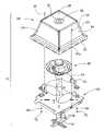
- FIG. 2is an exploded view of a first embodiment of the ceiling mount light.
- FIG. 3is an exploded view of a first embodiment of the motion detector assembly of the ceiling mount light.
- FIG. 4is an inverted bottom view of a second embodiment of the ceiling mount light.
- FIG. 5is an exploded view of a second embodiment of the ceiling mount light.
- FIG. 6is an exploded view of a second embodiment of the motion detector assembly of the ceiling mount light.
- FIGS. 1–6illustrate the ceiling mount light in an inverted position.
- a ceiling mount light with a 360-degree range of motion sensing in accordance with a first embodiment 10 of the present inventiongenerally comprises a lamp shade assembly 20 , a motion detector assembly 40 , and a base plate 60 .
- the lamp shade assembly 20may have a plurality of side panels 24 and a bottom panel 26 .
- the panelsmay be glass or some other transparent or translucent material known in the art.
- the side panels 24 and the bottom panel 26are supported by a support frame 22 and a frame base 30 .
- the frame base 30 of the lamp shade assembly 20is removably mounted to the base plate 60 in some manner, such as with a decorative nut 34 , base screws 68 , and base nuts 72 .
- a decorative ring 32surrounding a hollow recess 28 through which the spherical lens 44 protrudes.
- the motion sensor 48 of the motion detector assembly 40is positioned inside the spherical lens 44 and is positioned in the center of a printed circuit board assembly 46 .
- the motion sensor 48is used to detect movement, and the motion sensor 48 may be a passive infrared sensor, such as, for example, Model RE200B from Nippon Ceramic Co., Ltd., and Model LHi 778 from Perkin Elmer Optoelectronics.
- a photocell 53may also be utilized as a part of the electronics to make sure that the lights do not come on in the daytime. The photocell 53 is activated through light passing through spherical lens 44 and provides adequate light response to prevent on-off cycling of the light when the light is activated.
- a spherical partition 45may be used to separate the spherical lens 44 from the printed circuit board assembly 46 in order to isolate the electronics from the user to prevent access to the electronics. Further, the photocell may be recessed thereby increasing the accuracy of the dark detection scheme utilized by the electronics.
- a time regulating switch 54 and a sensitivity regulating switchare attached to the printed circuit board assembly 46 which may be a single pole mechanical slide switch to connect different fixed resistor values to change the timing or the sensitivity of the sensor.
- the time regulating switch 54 and the sensitivity regulating switch 56 positioned within the motion detector assembly 40may be adjustable switches, a variable resistor, or a variable capacitor, for manually adjusting the length of time the illumination stays on and the level of sensitivity of the motion detector.
- the time regulating switch 54 and sensitivity regulating switch 56may each be covered with a switch cover 50 .
- the printed circuit board assembly 46 , the motion sensor 48 , the time regulating switch 54 , the sensitivity regulating switch 56 , and each switch cover 50may be enveloped in a switch case 52 , which is partitioned for assembly and each part is detachable with case screws 47 .
- a rubber plug 58Directly above the printed circuit board assembly 46 on the opposing side of the motion sensor 48 is a rubber plug 58 which has a plurality of openings through which electrical wiring can be threaded. Rubber plug 58 prevents the ingress of moisture into the electrical compartment of the motion sensor assembly 40 .
- the rubber plug 58is mounted to a hollow extension cylinder 41 , through which electrical wiring can be threaded.
- the extension cylinder 41fits snuggly through a heat shield 43 and is attached to the center of the base plate 60 by screws 70 or other attachment mechanisms.
- Motion sensorsin general tend to malfunction when the ceiling mount light temperature increases above about 40° C., and the heat shield 43 serves to isolate the motion sensor 48 from radiant heat generated by the light bulbs.
- cross-ventilationis provided in the ceiling mount light 10 .
- a plurality of socket assemblies 62 for an illumination sourcesuch as a bulb 64 .
- the illumination sourcesmay be incandescent or other light emitting mechanisms known in the art.
- the base plate 60is attached to a cross bar assembly 66 with screws 70 and nuts which are used to mount the ceiling mount light 10 to an electrical junction box.
- the electronics and the motion detector mechanisms 40may be kept in close proximity below the heat shield 43 due to the generation of heat from lamps 64 . Temperature indications within the lamp shade area 20 may be as high as 100° C. However, since the motion sensor 48 determines movement based upon temperature fluctuations, it is necessary to separate the motion sensor 48 from the higher temperature areas of the lamp shade assembly 20 . As shown in the drawings, since the ceiling mount light having 360 degree motion sensing 10 of the present invention is inverted, the heat will tend to rise away from the motion sensor 48 and electronics thereby allowing adequate readings and sensor activation.
- the fixture 10may have venting apertures 63 a formed in the base 30 which acts in conjunction with the aperture or opening 75 to allow air to flow through the interior of the fixture and reduce the heat in the interior thereof.
- venting apertures 63 aformed in the base 30 which acts in conjunction with the aperture or opening 75 to allow air to flow through the interior of the fixture and reduce the heat in the interior thereof.
- alternative constructionsare available such that the motion sensor 48 may be completely separated from the motion detector electronics.
- the constituent elementsmay be placed in alternative and separate locations.
- a ceiling mount light with a 360-degree range of motion sensinggenerally comprises a lamp shade assembly 20 , a motion detector assembly 40 , and a base plate 60 .
- the lamp shade assembly 20has a plurality of side panels 24 and plurality of bottom panels 26 .
- the panelsmay be glass or some other transparent or translucent material known in the art.
- the side panels 24 and the bottom panels 26are supported by a support frame 22 and a frame base 30 .
- the frame base 30 of the lamp shade assembly 20is removably mounted to the base plate 60 in some manner, such as with hollow rivets 38 , base screws 68 , and decorative nuts 73 .
- a decorative ring 32surrounding a hollow recess 28 through which the single spherical lens 44 protrudes.
- the motion sensor 48 of the motion detector assembly 40is positioned inside the single spherical lens 44 and is positioned in the center of a printed circuit board assembly 46 .
- the motion sensor 48is used to detect the movement of heat and the motion sensor 48 may be a passive infrared sensor.
- a spherical partition 45may be used to separate the single spherical lens 44 from the printed circuit board assembly 48 as noted herein.
- a heat sink 42may be positioned around the single spherical lens 44 and mounted to a switch case 52 with pop rivet 49 or other attachment mechanisms.
- a time regulating switch 54 a two level lighting control switch 56 and a sensitivity regulating switch 74are attached to the printed circuit board assembly 46 .
- the time regulating switch 54 , the two level lighting control switch 56 and sensitivity regulating switch 74 positioned within the motion detector assembly 40may be adjustable switches, a variable resistor, or a variable capacitor, for manually adjusting the length of time the illumination stays on when motion is sensed, stays on at reduced power level for accent lighting, and the detection range respectively.
- the level of sensitivity of the motion detectoris up to about 30 feet.
- the time regulating switch 54 and sensitivity regulating switch 74are each covered with a switch cover 50 .
- the sensitivity regulating switchis externally adjustable with trimpot knob 51 .
- the printed circuit board assembly 46 , the motion sensor 48 , the time regulating switch 54 , the two level lighting control switch 56 , the sensitivity regulating switch 74 , each switch cover 50 and trimpot knob 51 ,are enveloped in the motion detector case 52 , which is partitioned for assembly and each half is detachable, with case screws 47 .
- the two level lighting control switch 56may be utilized to allow the lights 64 to emit light at a first low luminance under non-motion sensing conditions, for example 50% illumination, and at a higher luminance when motion is detected by the motion sensor or other motion sensor 48 .
- the time regulating switch 54may allow the user to select how long after sensing motion the lights remain at a higher output.
- a rubber plug 58which has a plurality of openings through which electrical wiring can be threaded.
- the rubber plug 58prevents ingress of moisture into the electronics compartment of the motion detector assembly 40 .
- the rubber plug 58is mounted to a hollow extension cylinder 41 , through which electrical wiring can be threaded.
- the extension cylinder 41fits snuggly through a heat shield 43 and is attached to the center of the base plate 60 with screws 70 .
- the heat shield 43serves to isolate the motion sensor 48 from radiant heat.
- ventilation holes 63positioned between the lamp shade assembly 20 and the base plate 60 and clearance between spherical lens 44 and decorative ring 32 provide cross-ventilation.
- the base plate 60is attached to a mounting bracket 66 with mounting screws 70 , which is used to mount the ceiling mount light 10 to an electrical junction box.
Landscapes
- Engineering & Computer Science (AREA)
- General Engineering & Computer Science (AREA)
- Arrangement Of Elements, Cooling, Sealing, Or The Like Of Lighting Devices (AREA)
- Non-Portable Lighting Devices Or Systems Thereof (AREA)
- Circuit Arrangement For Electric Light Sources In General (AREA)
Abstract
Description
Claims (33)
Priority Applications (4)
| Application Number | Priority Date | Filing Date | Title |
|---|---|---|---|
| US10/799,464US7109880B2 (en) | 2004-03-12 | 2004-03-12 | Ceiling mount light with 360-degree motion sensor |
| CA002500532ACA2500532A1 (en) | 2004-03-12 | 2005-03-10 | Ceiling mount light with 360-degree motion sensor |
| US11/532,755US7397386B2 (en) | 2004-03-12 | 2006-09-18 | Ceiling mount light with 360-degree motion sensor |
| US12/168,248US8049639B2 (en) | 2004-03-12 | 2008-07-07 | Ceiling mount light with 360-degree motion sensor |
Applications Claiming Priority (1)
| Application Number | Priority Date | Filing Date | Title |
|---|---|---|---|
| US10/799,464US7109880B2 (en) | 2004-03-12 | 2004-03-12 | Ceiling mount light with 360-degree motion sensor |
Related Child Applications (1)
| Application Number | Title | Priority Date | Filing Date |
|---|---|---|---|
| US11/532,755ContinuationUS7397386B2 (en) | 2004-03-12 | 2006-09-18 | Ceiling mount light with 360-degree motion sensor |
Publications (2)
| Publication Number | Publication Date |
|---|---|
| US20050200495A1 US20050200495A1 (en) | 2005-09-15 |
| US7109880B2true US7109880B2 (en) | 2006-09-19 |
Family
ID=34920516
Family Applications (3)
| Application Number | Title | Priority Date | Filing Date |
|---|---|---|---|
| US10/799,464Expired - LifetimeUS7109880B2 (en) | 2004-03-12 | 2004-03-12 | Ceiling mount light with 360-degree motion sensor |
| US11/532,755Expired - LifetimeUS7397386B2 (en) | 2004-03-12 | 2006-09-18 | Ceiling mount light with 360-degree motion sensor |
| US12/168,248Expired - LifetimeUS8049639B2 (en) | 2004-03-12 | 2008-07-07 | Ceiling mount light with 360-degree motion sensor |
Family Applications After (2)
| Application Number | Title | Priority Date | Filing Date |
|---|---|---|---|
| US11/532,755Expired - LifetimeUS7397386B2 (en) | 2004-03-12 | 2006-09-18 | Ceiling mount light with 360-degree motion sensor |
| US12/168,248Expired - LifetimeUS8049639B2 (en) | 2004-03-12 | 2008-07-07 | Ceiling mount light with 360-degree motion sensor |
Country Status (2)
| Country | Link |
|---|---|
| US (3) | US7109880B2 (en) |
| CA (1) | CA2500532A1 (en) |
Cited By (27)
| Publication number | Priority date | Publication date | Assignee | Title |
|---|---|---|---|---|
| US20060158709A1 (en)* | 2005-01-19 | 2006-07-20 | Gert Lettermann | Laser beam transmitter lighthouse |
| US20070229250A1 (en)* | 2006-03-28 | 2007-10-04 | Wireless Lighting Technologies, Llc | Wireless lighting |
| US20090079349A1 (en)* | 2004-03-12 | 2009-03-26 | Heathco Llc | Ceiling Mount Light with 360-Degree Motion Sensor |
| US20100230412A1 (en)* | 2007-10-29 | 2010-09-16 | Utc Fire & Security Corporation | Life safety mouting system and method |
| US20100302758A1 (en)* | 2009-06-02 | 2010-12-02 | Robert Wang | Multi-function replaceable modular led lamp |
| US20140092603A1 (en)* | 2011-06-14 | 2014-04-03 | Living Style Enterprises Limited | Led light bulb with light-shielding structure |
| US20140140067A1 (en)* | 2011-06-14 | 2014-05-22 | Ming-Yun Chen | Led light bulb with light-shielding structure |
| US20160186972A1 (en)* | 2014-08-13 | 2016-06-30 | Kenall Manufacturing Company | Luminaire with sensing and communication capabilities |
| US10034359B2 (en) | 2006-03-28 | 2018-07-24 | Wireless Environment, Llc | Cloud-connected off-grid lighting and video system |
| US10085332B2 (en) | 2006-03-28 | 2018-09-25 | A9.Com, Inc. | Motion sensitive communication device for controlling lighting |
| USD858381S1 (en)* | 2017-04-28 | 2019-09-03 | Waymo Llc | Fender sensor housing |
| US10485078B2 (en) | 2007-08-30 | 2019-11-19 | A9.Com, Inc. | Smart phone controlled wireless light bulb |
| US10601244B2 (en) | 2006-03-28 | 2020-03-24 | A9.Com, Inc. | Emergency lighting device with remote lighting |
| US11022290B2 (en) | 2019-02-01 | 2021-06-01 | Vaxcel International Co., Ltd. | LED security light with surrounding lamp shade |
| USRE48620E1 (en)* | 2014-02-02 | 2021-07-06 | Ideal Industries Lighting Llc | Troffer-style fixture |
| US11094182B2 (en) | 2018-08-02 | 2021-08-17 | Signify Holding B.V. | Using sensors to detect movement of light fixtures |
| US11129246B2 (en) | 2006-03-28 | 2021-09-21 | Amazon Technologies, Inc. | Grid connected coordinated lighting adapter |
| US11300443B2 (en)* | 2020-01-28 | 2022-04-12 | Commonwealth Edison Company | Cover for testing a light sensor |
| USD950404S1 (en) | 2019-05-01 | 2022-05-03 | Waymo Llc | Roof pod housing |
| USD957969S1 (en) | 2019-02-20 | 2022-07-19 | Waymo Llc | Sensor housing |
| USD964249S1 (en) | 2019-04-25 | 2022-09-20 | Waymo Llc | Perimeter sensor housing |
| USD964909S1 (en) | 2019-04-25 | 2022-09-27 | Waymo Llc | Perimeter sensor housing |
| USD964908S1 (en) | 2019-04-25 | 2022-09-27 | Waymo Llc | Perimeter sensor housing |
| USD965498S1 (en) | 2019-04-25 | 2022-10-04 | Waymo Llc | Perimeter sensor housing |
| USD968981S1 (en) | 2019-02-20 | 2022-11-08 | Waymo Llc | Sensor assembly |
| US11523488B1 (en) | 2006-03-28 | 2022-12-06 | Amazon Technologies, Inc. | Wirelessly controllable communication module |
| USD976719S1 (en) | 2019-05-01 | 2023-01-31 | Waymo Llc | Roof pod housing |
Families Citing this family (46)
| Publication number | Priority date | Publication date | Assignee | Title |
|---|---|---|---|---|
| DE202004018647U1 (en)* | 2004-12-01 | 2006-04-06 | Steinel Gmbh | SensorLight |
| US20080011697A1 (en)* | 2006-06-21 | 2008-01-17 | Berg David G | Rotary food storage system |
| EP2020563B1 (en)* | 2007-08-02 | 2015-01-14 | Hartmut S. Engel | Lighting device |
| US7934854B2 (en)* | 2008-03-31 | 2011-05-03 | Heathco Llc | Light fixture with optional animate object detector and heat sink |
| NL2002295C2 (en)* | 2008-12-05 | 2009-12-14 | Michel Robert Ten Wolde | Escape route illumination device for e.g. hotel, has lighting device mounted to wall at specific mounting height from floor, where lighting device illuminates predetermined area of floor |
| US8246204B2 (en)* | 2009-03-16 | 2012-08-21 | Abl Ip Holding Llc | Cover assembly for light emitting diodes |
| FR2951572B1 (en) | 2009-10-15 | 2012-04-27 | Hager Controls | MOVING CACHE DETECTOR |
| US10533892B2 (en) | 2015-10-06 | 2020-01-14 | View, Inc. | Multi-sensor device and system with a light diffusing element around a periphery of a ring of photosensors and an infrared sensor |
| US10690540B2 (en) | 2015-10-06 | 2020-06-23 | View, Inc. | Multi-sensor having a light diffusing element around a periphery of a ring of photosensors |
| KR100952446B1 (en) | 2010-01-22 | 2010-04-13 | 주식회사 한국리레이 | Sun tracking sensor unit having automatic pressure control function |
| US9746558B2 (en) | 2010-12-20 | 2017-08-29 | Mattel, Inc. | Proximity sensor apparatus for a game device |
| GB2498572B (en)* | 2012-01-20 | 2014-12-03 | Cp Electronics Ltd | Detector configured to detect the presence of a person |
| US9169983B2 (en)* | 2012-04-11 | 2015-10-27 | Cree, Inc. | Overhead light fixture and related method |
| US11674843B2 (en) | 2015-10-06 | 2023-06-13 | View, Inc. | Infrared cloud detector systems and methods |
| US9121580B1 (en)* | 2012-05-04 | 2015-09-01 | Cooper Technologies Company | Power door lighting fixture |
| US9163808B1 (en) | 2012-05-04 | 2015-10-20 | Cooper Technologies Company | Outdoor lighting fixture |
| US9261251B1 (en) | 2012-05-04 | 2016-02-16 | Cooper Technologies Company | Door for outdoor lighting fixture |
| US8974077B2 (en) | 2012-07-30 | 2015-03-10 | Ultravision Technologies, Llc | Heat sink for LED light source |
| US9163817B2 (en)* | 2012-08-13 | 2015-10-20 | Ir-Tec International Ltd. | Ceiling mount occupancy sensor module and apparatus using the ceiling mount occupancy sensor module |
| DE202013102915U1 (en)* | 2013-07-03 | 2014-10-06 | Zumtobel Lighting Gmbh | Luminaire with an additional element in the form of an emergency light element and / or a transmitting or receiving element for transmitting and / or receiving electromagnetic radiation |
| CN104696781A (en)* | 2013-12-04 | 2015-06-10 | 海洋王(东莞)照明科技有限公司 | Lamp |
| WO2015101420A1 (en)* | 2014-01-02 | 2015-07-09 | Tyco Electronics Nederland B.V. | Led socket assembly |
| US10375791B2 (en) | 2014-03-19 | 2019-08-06 | System Lighting Solutions, Llc | Lighting system and method of installing |
| US9506609B1 (en) | 2014-03-19 | 2016-11-29 | System Lighting Solutions, Llc | Light system and method of installing |
| TW202130977A (en) | 2014-09-29 | 2021-08-16 | 美商唯景公司 | Combi-sensor systems |
| US11781903B2 (en) | 2014-09-29 | 2023-10-10 | View, Inc. | Methods and systems for controlling tintable windows with cloud detection |
| US10234596B2 (en) | 2014-09-29 | 2019-03-19 | View, Inc. | Sunlight intensity or cloud detection with variable distance sensing |
| US11566938B2 (en) | 2014-09-29 | 2023-01-31 | View, Inc. | Methods and systems for controlling tintable windows with cloud detection |
| US10001266B2 (en)* | 2015-06-22 | 2018-06-19 | Cree, Inc. | Trapezoidal pir sensor lens |
| US9874341B2 (en)* | 2015-06-29 | 2018-01-23 | Cree, Inc. | Double fresnel pir lens |
| CN106439631B (en)* | 2015-08-10 | 2020-03-27 | 通用电气照明解决方案有限公司 | Ventilation external member and embedded lamps and lanterns subassembly that has ventilation function |
| US11255722B2 (en) | 2015-10-06 | 2022-02-22 | View, Inc. | Infrared cloud detector systems and methods |
| USD835305S1 (en) | 2016-06-28 | 2018-12-04 | System Lighting Solutions, Llc | Light and track assembly |
| USD810354S1 (en)* | 2016-06-28 | 2018-02-13 | Tye T. Farnsworth | Light assembly |
| USD811648S1 (en)* | 2016-06-28 | 2018-02-27 | System Lighting Solutions, Llc | Lens for lights |
| USD823496S1 (en) | 2016-06-28 | 2018-07-17 | System Lighting Solutions, Llc | Light and track assembly |
| USD816889S1 (en) | 2016-06-28 | 2018-05-01 | System Lighting Solutions, Llc | Track assembly for lights |
| CN206530929U (en)* | 2017-02-07 | 2017-09-29 | 中山和欣灯饰有限公司 | Garden senses lamp |
| CN107172840B (en)* | 2017-06-08 | 2022-11-15 | 歌尔科技有限公司 | Thermal-insulated fixed knot of cloud platform Camera inertia measuring unit constructs |
| JP6967961B2 (en)* | 2017-12-21 | 2021-11-17 | スタンレー電気株式会社 | Light source unit for vehicle lighting equipment and vehicle lighting equipment |
| US10571099B2 (en)* | 2018-04-20 | 2020-02-25 | Eaton Intelligent Power Limited | Surface mount luminaire |
| US11252828B2 (en)* | 2019-09-05 | 2022-02-15 | Geoffrey M. Hopkins | Housing and wall mount casing for google nest guard or similar article |
| US11365847B2 (en)* | 2020-04-22 | 2022-06-21 | Keystone Sales Group, Inc. | Motion activated warehouse safety light |
| USD895192S1 (en) | 2020-05-06 | 2020-09-01 | Zihua Gong | Lamp |
| US11940106B2 (en) | 2022-08-31 | 2024-03-26 | RAB Lighting Inc. | Low profile modular lighting device with flexible installation |
| WO2024120443A1 (en)* | 2022-12-09 | 2024-06-13 | 苏州欧普照明有限公司 | Infrared induction circuit and light fixture |
Citations (12)
| Publication number | Priority date | Publication date | Assignee | Title |
|---|---|---|---|---|
| US4717910A (en)* | 1985-11-12 | 1988-01-05 | Scripps Keith A | Detector and light assembly |
| US4823051A (en)* | 1987-05-21 | 1989-04-18 | Pittway Corporation | Infrared actuated control switch assembly |
| USD341441S (en) | 1992-05-27 | 1993-11-16 | Troy Lighting Incorporated | Diffusor for a recessed lighting fixture |
| US5590953A (en)* | 1995-04-27 | 1997-01-07 | Regent Lighting Corporation | Directable decorative lantern with motion sensor |
| US5626417A (en) | 1996-04-16 | 1997-05-06 | Heath Company | Motion detector assembly for use with a decorative coach lamp |
| US5662411A (en) | 1995-03-20 | 1997-09-02 | Regent Lighting Corporation | Motion activated light fixture with fixed sensor |
| US6100803A (en) | 1999-02-10 | 2000-08-08 | Chang; Wen-Hsiang | Infrared illuminative warning detector |
| US6151529A (en)* | 1995-02-02 | 2000-11-21 | Hubbell Incorporated | Motion sensing system with adaptive timing for controlling lighting fixtures |
| US6168282B1 (en)* | 1997-10-28 | 2001-01-02 | Tseng-Lu Chien | Electro-luminescent lighting arrangement for a lighting apparatus with a lamp holder |
| CA2277645A1 (en)* | 1999-07-15 | 2001-01-15 | Quality Craft Importers Ltd. | Motion detector within flush mounted ceiling light |
| US20030117803A1 (en) | 2001-12-25 | 2003-06-26 | Hsing Chen | Energy saving type of light emitting diode lamp |
| US6940230B2 (en)* | 2002-05-30 | 2005-09-06 | Hubbell Incorporated | Modular lamp controller |
Family Cites Families (8)
| Publication number | Priority date | Publication date | Assignee | Title |
|---|---|---|---|---|
| US3749903A (en)* | 1972-05-02 | 1973-07-31 | P Belokin | Psychedelic reflection device |
| US4757204A (en)* | 1986-01-28 | 1988-07-12 | Cerberus Ag | Ceiling mounted passive infrared intrusion detector with dome shaped lens |
| US5857769A (en)* | 1996-07-11 | 1999-01-12 | Beggs; William C. | Condensation diversion system in a lamp fixture |
| JP3972395B2 (en)* | 1996-12-20 | 2007-09-05 | 日立ライティング株式会社 | Ceiling light fixture with infrared sensor |
| US6348691B1 (en)* | 1999-12-30 | 2002-02-19 | Cordelia Lighting, Inc. | Motion detector with extra-wide angle mirrored optics |
| US6948831B1 (en)* | 2004-01-20 | 2005-09-27 | Shams Naqvi | Recessed light assembly adapted for use with motion detector |
| US7377667B2 (en)* | 2004-02-13 | 2008-05-27 | Simon Nicholas Richmond | Light device |
| US7109880B2 (en) | 2004-03-12 | 2006-09-19 | Desa Ip Llc | Ceiling mount light with 360-degree motion sensor |
- 2004
- 2004-03-12USUS10/799,464patent/US7109880B2/ennot_activeExpired - Lifetime
- 2005
- 2005-03-10CACA002500532Apatent/CA2500532A1/ennot_activeAbandoned
- 2006
- 2006-09-18USUS11/532,755patent/US7397386B2/ennot_activeExpired - Lifetime
- 2008
- 2008-07-07USUS12/168,248patent/US8049639B2/ennot_activeExpired - Lifetime
Patent Citations (12)
| Publication number | Priority date | Publication date | Assignee | Title |
|---|---|---|---|---|
| US4717910A (en)* | 1985-11-12 | 1988-01-05 | Scripps Keith A | Detector and light assembly |
| US4823051A (en)* | 1987-05-21 | 1989-04-18 | Pittway Corporation | Infrared actuated control switch assembly |
| USD341441S (en) | 1992-05-27 | 1993-11-16 | Troy Lighting Incorporated | Diffusor for a recessed lighting fixture |
| US6151529A (en)* | 1995-02-02 | 2000-11-21 | Hubbell Incorporated | Motion sensing system with adaptive timing for controlling lighting fixtures |
| US5662411A (en) | 1995-03-20 | 1997-09-02 | Regent Lighting Corporation | Motion activated light fixture with fixed sensor |
| US5590953A (en)* | 1995-04-27 | 1997-01-07 | Regent Lighting Corporation | Directable decorative lantern with motion sensor |
| US5626417A (en) | 1996-04-16 | 1997-05-06 | Heath Company | Motion detector assembly for use with a decorative coach lamp |
| US6168282B1 (en)* | 1997-10-28 | 2001-01-02 | Tseng-Lu Chien | Electro-luminescent lighting arrangement for a lighting apparatus with a lamp holder |
| US6100803A (en) | 1999-02-10 | 2000-08-08 | Chang; Wen-Hsiang | Infrared illuminative warning detector |
| CA2277645A1 (en)* | 1999-07-15 | 2001-01-15 | Quality Craft Importers Ltd. | Motion detector within flush mounted ceiling light |
| US20030117803A1 (en) | 2001-12-25 | 2003-06-26 | Hsing Chen | Energy saving type of light emitting diode lamp |
| US6940230B2 (en)* | 2002-05-30 | 2005-09-06 | Hubbell Incorporated | Modular lamp controller |
Cited By (61)
| Publication number | Priority date | Publication date | Assignee | Title |
|---|---|---|---|---|
| US8049639B2 (en) | 2004-03-12 | 2011-11-01 | Heathco, Llc | Ceiling mount light with 360-degree motion sensor |
| US20090079349A1 (en)* | 2004-03-12 | 2009-03-26 | Heathco Llc | Ceiling Mount Light with 360-Degree Motion Sensor |
| US20060158709A1 (en)* | 2005-01-19 | 2006-07-20 | Gert Lettermann | Laser beam transmitter lighthouse |
| US8915626B2 (en)* | 2005-01-19 | 2014-12-23 | Trimble Kaiserslautern Gmbh | Laser beam transmitter lighthouse |
| US10966306B1 (en) | 2006-03-28 | 2021-03-30 | Amazon Technologies, Inc. | Bridge device for connecting electronic devices |
| US10390413B2 (en) | 2006-03-28 | 2019-08-20 | A9.Com, Inc. | Wirelessly controllable communication module |
| US11101686B1 (en) | 2006-03-28 | 2021-08-24 | Amazon Technologies, Inc. | Emergency lighting device with remote lighting |
| US8203445B2 (en)* | 2006-03-28 | 2012-06-19 | Wireless Environment, Llc | Wireless lighting |
| US20070229250A1 (en)* | 2006-03-28 | 2007-10-04 | Wireless Lighting Technologies, Llc | Wireless lighting |
| US11129246B2 (en) | 2006-03-28 | 2021-09-21 | Amazon Technologies, Inc. | Grid connected coordinated lighting adapter |
| US10999914B1 (en) | 2006-03-28 | 2021-05-04 | Amazon Technologies, Inc. | Motion sensitive lighting devices |
| US11523488B1 (en) | 2006-03-28 | 2022-12-06 | Amazon Technologies, Inc. | Wirelessly controllable communication module |
| US9342967B2 (en) | 2006-03-28 | 2016-05-17 | Wireless Environment, Llc | Motion activated off grid LED light |
| US10912178B1 (en) | 2006-03-28 | 2021-02-02 | Amazon Technologies, Inc. | System for providing video on demand |
| US10034359B2 (en) | 2006-03-28 | 2018-07-24 | Wireless Environment, Llc | Cloud-connected off-grid lighting and video system |
| US10085332B2 (en) | 2006-03-28 | 2018-09-25 | A9.Com, Inc. | Motion sensitive communication device for controlling lighting |
| US10098211B2 (en) | 2006-03-28 | 2018-10-09 | A9.Com, Inc. | Wirelessly controllable lighting module |
| US10117315B2 (en) | 2006-03-28 | 2018-10-30 | A9.Com, Inc. | Network of motion sensor lights with synchronized operation |
| US10342104B2 (en) | 2006-03-28 | 2019-07-02 | A9.Com, Inc. | Video on demand for communication devices |
| US11109471B1 (en) | 2006-03-28 | 2021-08-31 | Amazon Technologies, Inc. | Bridge device for connecting electronic devices |
| US10601244B2 (en) | 2006-03-28 | 2020-03-24 | A9.Com, Inc. | Emergency lighting device with remote lighting |
| US10448491B1 (en) | 2006-03-28 | 2019-10-15 | Amazon Technologies, Inc. | Motion sensitive communication device for controlling IR lighting |
| US10448489B2 (en) | 2006-03-28 | 2019-10-15 | A9.Com, Inc. | Motion sensitive communication device for controlling IR lighting |
| US10499478B2 (en) | 2006-03-28 | 2019-12-03 | A9.Com, Inc. | Cloud-connected off-grid lighting and video system |
| US10485078B2 (en) | 2007-08-30 | 2019-11-19 | A9.Com, Inc. | Smart phone controlled wireless light bulb |
| US20100230412A1 (en)* | 2007-10-29 | 2010-09-16 | Utc Fire & Security Corporation | Life safety mouting system and method |
| US8910820B2 (en)* | 2007-10-29 | 2014-12-16 | Utc Fire & Security Corporation | Life safety mounting system and method |
| US20100302758A1 (en)* | 2009-06-02 | 2010-12-02 | Robert Wang | Multi-function replaceable modular led lamp |
| US8066392B2 (en)* | 2009-06-02 | 2011-11-29 | Ceramate Technical Co., Ltd. | Multi-function replaceable modular LED lamp |
| US20140140067A1 (en)* | 2011-06-14 | 2014-05-22 | Ming-Yun Chen | Led light bulb with light-shielding structure |
| US20140092603A1 (en)* | 2011-06-14 | 2014-04-03 | Living Style Enterprises Limited | Led light bulb with light-shielding structure |
| USRE49228E1 (en)* | 2014-02-02 | 2022-10-04 | Ideal Industries Lighting Llc | Troffer-style fixture |
| USRE48620E1 (en)* | 2014-02-02 | 2021-07-06 | Ideal Industries Lighting Llc | Troffer-style fixture |
| US20160186972A1 (en)* | 2014-08-13 | 2016-06-30 | Kenall Manufacturing Company | Luminaire with sensing and communication capabilities |
| USD1078587S1 (en) | 2017-04-28 | 2025-06-10 | Waymo Llc | Fender sensor housing |
| USD954620S1 (en) | 2017-04-28 | 2022-06-14 | Waymo Llc | Fender sensor housing |
| USD858381S1 (en)* | 2017-04-28 | 2019-09-03 | Waymo Llc | Fender sensor housing |
| US11094182B2 (en) | 2018-08-02 | 2021-08-17 | Signify Holding B.V. | Using sensors to detect movement of light fixtures |
| US11022290B2 (en) | 2019-02-01 | 2021-06-01 | Vaxcel International Co., Ltd. | LED security light with surrounding lamp shade |
| USD991811S1 (en) | 2019-02-20 | 2023-07-11 | Waymo Llc | Sensor housing |
| USD957968S1 (en) | 2019-02-20 | 2022-07-19 | Waymo Llc | Sensor housing |
| USD957967S1 (en) | 2019-02-20 | 2022-07-19 | Waymo Llc | Sensor housing |
| USD1050913S1 (en) | 2019-02-20 | 2024-11-12 | Waymo Llc | Sensor housing |
| USD957969S1 (en) | 2019-02-20 | 2022-07-19 | Waymo Llc | Sensor housing |
| USD1038793S1 (en) | 2019-02-20 | 2024-08-13 | Waymo Llc | Sensor assembly |
| USD1038787S1 (en) | 2019-02-20 | 2024-08-13 | Waymo Llc | Sensor housing |
| USD968981S1 (en) | 2019-02-20 | 2022-11-08 | Waymo Llc | Sensor assembly |
| USD996996S1 (en) | 2019-02-20 | 2023-08-29 | Waymo Llc | Sensor assembly |
| USD991810S1 (en) | 2019-02-20 | 2023-07-11 | Waymo Llc | Sensor housing |
| USD991812S1 (en) | 2019-02-20 | 2023-07-11 | Waymo Llc | Sensor housing |
| USD964908S1 (en) | 2019-04-25 | 2022-09-27 | Waymo Llc | Perimeter sensor housing |
| USD978058S1 (en) | 2019-04-25 | 2023-02-14 | Waymo Llc | Perimeter sensor housing |
| USD965498S1 (en) | 2019-04-25 | 2022-10-04 | Waymo Llc | Perimeter sensor housing |
| USD964909S1 (en) | 2019-04-25 | 2022-09-27 | Waymo Llc | Perimeter sensor housing |
| USD964249S1 (en) | 2019-04-25 | 2022-09-20 | Waymo Llc | Perimeter sensor housing |
| USD991809S1 (en) | 2019-05-01 | 2023-07-11 | Waymo Llc | Roof pod housing |
| USD976719S1 (en) | 2019-05-01 | 2023-01-31 | Waymo Llc | Roof pod housing |
| USD1033246S1 (en) | 2019-05-01 | 2024-07-02 | Waymo Llc | Roof pod housing |
| USD1037031S1 (en) | 2019-05-01 | 2024-07-30 | Waymo Llc | Roof pod housing |
| USD950404S1 (en) | 2019-05-01 | 2022-05-03 | Waymo Llc | Roof pod housing |
| US11300443B2 (en)* | 2020-01-28 | 2022-04-12 | Commonwealth Edison Company | Cover for testing a light sensor |
Also Published As
| Publication number | Publication date |
|---|---|
| US20090079349A1 (en) | 2009-03-26 |
| US7397386B2 (en) | 2008-07-08 |
| CA2500532A1 (en) | 2005-09-12 |
| US20050200495A1 (en) | 2005-09-15 |
| US20070064427A1 (en) | 2007-03-22 |
| US8049639B2 (en) | 2011-11-01 |
Similar Documents
| Publication | Publication Date | Title |
|---|---|---|
| US7109880B2 (en) | Ceiling mount light with 360-degree motion sensor | |
| US6909239B2 (en) | Dual LED/incandescent security fixture | |
| KR200334515Y1 (en) | Automatic control energy savimg lamp builted in combination sensor | |
| US8506121B2 (en) | Flow-through LED lighting system | |
| US6350039B1 (en) | Wall switch and lamp assembly | |
| US20050259416A1 (en) | Dual lighting system | |
| US20110304268A1 (en) | Lighting device having a semiconductor light source and at least one sensor | |
| KR101292098B1 (en) | Lighting for led automatic control with sensor | |
| US20070177384A1 (en) | Motion sensing lighting fixture | |
| KR101868383B1 (en) | LED Lighting apparatus and control method thereof | |
| WO2005024898A3 (en) | Integrated lamp with feedback and wireless control | |
| US20080074873A1 (en) | Wall lamp | |
| WO2012056268A1 (en) | A common light module for decorative external lighting structures | |
| US12104775B2 (en) | Lighting system with improved sensor control | |
| KR101875570B1 (en) | Circular sensor light | |
| KR101111570B1 (en) | LED lighting device | |
| CA3038496C (en) | Luminaire with adapter collar | |
| US20080197783A1 (en) | Composite illumination module | |
| KR101198398B1 (en) | LED lighting lamp that improve object sensing and illumination sensing reaction | |
| KR101042946B1 (en) | LED lighting system with energy saving effect | |
| KR101739492B1 (en) | Floodlight with ir led and white led | |
| JP2010009959A (en) | Illumination fixture | |
| KR101456372B1 (en) | Led lamp | |
| KR100568944B1 (en) | Sensor light using light emitting diode | |
| JPH10208521A (en) | Automatic lighting system |
Legal Events
| Date | Code | Title | Description |
|---|---|---|---|
| AS | Assignment | Owner name:DESA IP, LLC, FLORIDA Free format text:ASSIGNMENT OF ASSIGNORS INTEREST;ASSIGNORS:SIBALICH, GREGORY L.;CORNETT, ROGER DENNIS;RICKY, CHIK KIN WING;REEL/FRAME:015095/0190;SIGNING DATES FROM 20040310 TO 20040311 | |
| STCF | Information on status: patent grant | Free format text:PATENTED CASE | |
| AS | Assignment | Owner name:DESA IP, LLC, KENTUCKY Free format text:PARTIAL RELEASE OF SECURITY INTEREST;ASSIGNOR:MERRILL LYNCH CAPITAL, A DIVISION OF MERRILL LYNCH BUSINESS FINANCIAL SERVICES INC., AS ADMINISTRATIVE AGENT;REEL/FRAME:019825/0251 Effective date:20070830 Owner name:DESA IP, LLC,KENTUCKY Free format text:PARTIAL RELEASE OF SECURITY INTEREST;ASSIGNOR:MERRILL LYNCH CAPITAL, A DIVISION OF MERRILL LYNCH BUSINESS FINANCIAL SERVICES INC., AS ADMINISTRATIVE AGENT;REEL/FRAME:019825/0251 Effective date:20070830 | |
| AS | Assignment | Owner name:HEATHCO LLC, ILLINOIS Free format text:ASSIGNMENT OF ASSIGNORS INTEREST;ASSIGNOR:DESA IP, LLC;REEL/FRAME:020010/0766 Effective date:20070828 Owner name:HEATHCO LLC,ILLINOIS Free format text:ASSIGNMENT OF ASSIGNORS INTEREST;ASSIGNOR:DESA IP, LLC;REEL/FRAME:020010/0766 Effective date:20070828 | |
| FPAY | Fee payment | Year of fee payment:4 | |
| FPAY | Fee payment | Year of fee payment:8 | |
| AS | Assignment | Owner name:LBC CREDIT PARTNERS III, L.P., AS AGENT, PENNSYLVA Free format text:SECURITY INTEREST;ASSIGNOR:HEATHCO LLC;REEL/FRAME:037484/0127 Effective date:20160111 | |
| AS | Assignment | Owner name:WELLS FARGO BANK, NATIONAL ASSOCIATION, CALIFORNIA Free format text:PATENT SECURITY AGREEMENT;ASSIGNOR:HEATHCO LLC;REEL/FRAME:037693/0533 Effective date:20160111 | |
| FEPP | Fee payment procedure | Free format text:PAT HOLDER CLAIMS SMALL ENTITY STATUS, ENTITY STATUS SET TO SMALL (ORIGINAL EVENT CODE: LTOS); ENTITY STATUS OF PATENT OWNER: SMALL ENTITY | |
| MAFP | Maintenance fee payment | Free format text:PAYMENT OF MAINTENANCE FEE, 12TH YR, SMALL ENTITY (ORIGINAL EVENT CODE: M2553) Year of fee payment:12 | |
| AS | Assignment | Owner name:HEATHCO LLC, KENTUCKY Free format text:RELEASE BY SECURED PARTY;ASSIGNOR:LBC CREDIT PARTNERS III, L.P., AS AGENT;REEL/FRAME:055349/0140 Effective date:20201014 | |
| AS | Assignment | Owner name:HEATHCO LLC, KENTUCKY Free format text:RELEASE BY SECURED PARTY;ASSIGNOR:WELLS FARGO BANK, NATIONAL ASSOCIATION;REEL/FRAME:057946/0154 Effective date:20211008 | |
| AS | Assignment | Owner name:THE TORONTO-DOMINION BANK, CANADA Free format text:SECURITY INTEREST;ASSIGNOR:HEATHCO LLC;REEL/FRAME:058980/0186 Effective date:20211216 | |
| AS | Assignment | Owner name:ALTER DOMUS (US) LLC, ILLINOIS Free format text:ASSIGNMENT FOR SECURITY - PATENTS AND INDUSTRIAL DESIGNS;ASSIGNORS:GLOBE ELECTRIC COMPANY INC.;HEATHCO LLC;REEL/FRAME:068235/0742 Effective date:20240725 | |
| AS | Assignment | Owner name:BANK OF AMERICA, N.A., NEW YORK Free format text:ASSIGNMENT FOR SECURITY - PATENTS AND INDUSTRIAL DESIGNS;ASSIGNORS:GLOBE ELECTRIC COMPANY INC.;HEATHCO LLC;REEL/FRAME:068235/0716 Effective date:20240725 | |
| AS | Assignment | Owner name:HEATHCO, LLC, KENTUCKY Free format text:RELEASE BY SECURED PARTY;ASSIGNOR:TORONTO-DOMINION BANK;REEL/FRAME:068654/0433 Effective date:20240726 Owner name:GLOBE ELECTRIC COMPANY INC., CANADA Free format text:RELEASE BY SECURED PARTY;ASSIGNOR:TORONTO-DOMINION BANK;REEL/FRAME:068654/0433 Effective date:20240726 |