US7108689B2 - Method and apparatus for electromagnetic treatment of the skin, including hair depilation - Google Patents
Method and apparatus for electromagnetic treatment of the skin, including hair depilationDownload PDFInfo
- Publication number
- US7108689B2 US7108689B2US10/246,722US24672202AUS7108689B2US 7108689 B2US7108689 B2US 7108689B2US 24672202 AUS24672202 AUS 24672202AUS 7108689 B2US7108689 B2US 7108689B2
- Authority
- US
- United States
- Prior art keywords
- skin
- light
- flashlamp
- housing
- hair
- Prior art date
- Legal status (The legal status is an assumption and is not a legal conclusion. Google has not performed a legal analysis and makes no representation as to the accuracy of the status listed.)
- Expired - Fee Related, expires
Links
- 238000011282treatmentMethods0.000titleclaimsabstractdescription94
- 238000000034methodMethods0.000titleclaimsabstractdescription40
- 210000004209hairAnatomy0.000titleabstractdescription90
- 230000035617depilationEffects0.000titledescription4
- 238000001228spectrumMethods0.000claimsdescription55
- 230000003287optical effectEffects0.000claimsdescription25
- 230000005855radiationEffects0.000claimsdescription18
- 230000005670electromagnetic radiationEffects0.000claimsdescription14
- 239000011521glassSubstances0.000claimsdescription14
- 230000005540biological transmissionEffects0.000claimsdescription6
- 238000001914filtrationMethods0.000claimsdescription4
- 239000012780transparent materialSubstances0.000claimsdescription4
- 210000003491skinAnatomy0.000description151
- 239000000499gelSubstances0.000description63
- 239000000835fiberSubstances0.000description51
- 210000001519tissueAnatomy0.000description42
- 210000003780hair follicleAnatomy0.000description33
- 239000013307optical fiberSubstances0.000description30
- 230000035515penetrationEffects0.000description29
- 239000000463materialSubstances0.000description27
- 210000002615epidermisAnatomy0.000description25
- 238000010521absorption reactionMethods0.000description22
- 239000003990capacitorSubstances0.000description20
- 239000008280bloodSubstances0.000description18
- 210000004369bloodAnatomy0.000description18
- 238000001816coolingMethods0.000description18
- 230000008878couplingEffects0.000description18
- 238000010168coupling processMethods0.000description18
- 238000005859coupling reactionMethods0.000description18
- XLYOFNOQVPJJNP-UHFFFAOYSA-NwaterSubstancesOXLYOFNOQVPJJNP-UHFFFAOYSA-N0.000description17
- 230000001934delayEffects0.000description15
- 238000009826distributionMethods0.000description13
- 210000004204blood vesselAnatomy0.000description12
- 238000005345coagulationMethods0.000description12
- 230000015271coagulationEffects0.000description12
- 238000010438heat treatmentMethods0.000description10
- 230000008901benefitEffects0.000description9
- 208000017520skin diseaseDiseases0.000description9
- 208000012641Pigmentation diseaseDiseases0.000description8
- 101100449816Saccharomyces cerevisiae (strain ATCC 204508 / S288c) GTO1 geneProteins0.000description8
- 210000004207dermisAnatomy0.000description8
- 230000006378damageEffects0.000description7
- 208000037265diseases, disorders, signs and symptomsDiseases0.000description7
- 208000035475disorderDiseases0.000description7
- 230000003993interactionEffects0.000description6
- 230000019612pigmentationEffects0.000description6
- 230000003595spectral effectEffects0.000description6
- 230000001225therapeutic effectEffects0.000description6
- 208000019553vascular diseaseDiseases0.000description6
- 230000001427coherent effectEffects0.000description5
- 230000000694effectsEffects0.000description5
- 239000012530fluidSubstances0.000description5
- 238000002310reflectometryMethods0.000description5
- 238000005253claddingMethods0.000description4
- 238000000576coating methodMethods0.000description4
- 230000006870functionEffects0.000description4
- 239000007789gasSubstances0.000description4
- 238000004519manufacturing processMethods0.000description4
- 238000012986modificationMethods0.000description4
- 230000004048modificationEffects0.000description4
- 238000012545processingMethods0.000description4
- 238000012546transferMethods0.000description4
- 210000003462veinAnatomy0.000description4
- 108010064719OxyhemoglobinsProteins0.000description3
- 239000011248coating agentSubstances0.000description3
- 239000002537cosmeticSubstances0.000description3
- 238000005286illuminationMethods0.000description3
- 230000031700light absorptionEffects0.000description3
- 230000007935neutral effectEffects0.000description3
- 230000008569processEffects0.000description3
- 239000007787solidSubstances0.000description3
- XKRFYHLGVUSROY-UHFFFAOYSA-NArgonChemical compound[Ar]XKRFYHLGVUSROY-UHFFFAOYSA-N0.000description2
- XUMBMVFBXHLACL-UHFFFAOYSA-NMelaninChemical compoundO=C1C(=O)C(C2=CNC3=C(C(C(=O)C4=C32)=O)C)=C2C4=CNC2=C1CXUMBMVFBXHLACL-UHFFFAOYSA-N0.000description2
- 208000006787Port-Wine StainDiseases0.000description2
- 208000006981Skin AbnormalitiesDiseases0.000description2
- NIXOWILDQLNWCW-UHFFFAOYSA-Nacrylic acid groupChemical groupC(C=C)(=O)ONIXOWILDQLNWCW-UHFFFAOYSA-N0.000description2
- 229910052782aluminiumInorganic materials0.000description2
- XAGFODPZIPBFFR-UHFFFAOYSA-NaluminiumChemical compound[Al]XAGFODPZIPBFFR-UHFFFAOYSA-N0.000description2
- 230000002238attenuated effectEffects0.000description2
- 238000006243chemical reactionMethods0.000description2
- 230000001112coagulating effectEffects0.000description2
- 238000009792diffusion processMethods0.000description2
- 238000002474experimental methodMethods0.000description2
- 238000010304firingMethods0.000description2
- 230000001788irregularEffects0.000description2
- 230000000670limiting effectEffects0.000description2
- 238000005259measurementMethods0.000description2
- 229910052751metalInorganic materials0.000description2
- 239000002184metalSubstances0.000description2
- 238000001208nuclear magnetic resonance pulse sequenceMethods0.000description2
- 238000011369optimal treatmentMethods0.000description2
- 239000010453quartzSubstances0.000description2
- 230000002441reversible effectEffects0.000description2
- VYPSYNLAJGMNEJ-UHFFFAOYSA-Nsilicon dioxideInorganic materialsO=[Si]=OVYPSYNLAJGMNEJ-UHFFFAOYSA-N0.000description2
- 231100000444skin lesionToxicity0.000description2
- 230000036555skin typeEffects0.000description2
- 239000004575stoneSubstances0.000description2
- 230000007704transitionEffects0.000description2
- 238000002604ultrasonographyMethods0.000description2
- 231100000216vascular lesionToxicity0.000description2
- INGWEZCOABYORO-UHFFFAOYSA-N2-(furan-2-yl)-7-methyl-1h-1,8-naphthyridin-4-oneChemical compoundN=1C2=NC(C)=CC=C2C(O)=CC=1C1=CC=CO1INGWEZCOABYORO-UHFFFAOYSA-N0.000description1
- 206010059245AngiopathyDiseases0.000description1
- 230000005457Black-body radiationEffects0.000description1
- 241000167854Bourreria succulentaSpecies0.000description1
- 208000031857Campbell de Morgan spotsDiseases0.000description1
- RYGMFSIKBFXOCR-UHFFFAOYSA-NCopperChemical compound[Cu]RYGMFSIKBFXOCR-UHFFFAOYSA-N0.000description1
- 208000000913Kidney CalculiDiseases0.000description1
- 206010028980NeoplasmDiseases0.000description1
- 206010029148NephrolithiasisDiseases0.000description1
- 201000004681PsoriasisDiseases0.000description1
- 206010039580ScarDiseases0.000description1
- 206010041519Spider naevusDiseases0.000description1
- 206010054830Throat lesionDiseases0.000description1
- 208000009443Vascular MalformationsDiseases0.000description1
- 239000000654additiveSubstances0.000description1
- 229910052786argonInorganic materials0.000description1
- 210000001367arteryAnatomy0.000description1
- QVGXLLKOCUKJST-UHFFFAOYSA-Natomic oxygenChemical compound[O]QVGXLLKOCUKJST-UHFFFAOYSA-N0.000description1
- 230000017531blood circulationEffects0.000description1
- 238000009529body temperature measurementMethods0.000description1
- 201000011510cancerDiseases0.000description1
- 238000003763carbonizationMethods0.000description1
- 238000001311chemical methods and processMethods0.000description1
- 235000019693cherriesNutrition0.000description1
- 238000004140cleaningMethods0.000description1
- 239000012141concentrateSubstances0.000description1
- 239000000470constituentSubstances0.000description1
- 238000010276constructionMethods0.000description1
- 239000002826coolantSubstances0.000description1
- 229910052802copperInorganic materials0.000description1
- 239000010949copperSubstances0.000description1
- 238000012937correctionMethods0.000description1
- 238000005520cutting processMethods0.000description1
- 230000003247decreasing effectEffects0.000description1
- 230000007812deficiencyEffects0.000description1
- 108010002255deoxyhemoglobinProteins0.000description1
- 230000001419dependent effectEffects0.000description1
- 238000013461designMethods0.000description1
- 238000010586diagramMethods0.000description1
- 230000003292diminished effectEffects0.000description1
- 230000008034disappearanceEffects0.000description1
- 239000002019doping agentSubstances0.000description1
- 239000003814drugSubstances0.000description1
- 230000002500effect on skinEffects0.000description1
- 238000005868electrolysis reactionMethods0.000description1
- 238000001704evaporationMethods0.000description1
- 230000008020evaporationEffects0.000description1
- 238000004880explosionMethods0.000description1
- 238000011049fillingMethods0.000description1
- 230000004907fluxEffects0.000description1
- 208000001130gallstonesDiseases0.000description1
- 239000003365glass fiberSubstances0.000description1
- 230000036074healthy skinEffects0.000description1
- 208000014617hemorrhoidDiseases0.000description1
- 230000002209hydrophobic effectEffects0.000description1
- 238000010348incorporationMethods0.000description1
- 230000010354integrationEffects0.000description1
- 238000011835investigationMethods0.000description1
- 210000003734kidneyAnatomy0.000description1
- 238000013532laser treatmentMethods0.000description1
- 238000002789length controlMethods0.000description1
- 230000003902lesionEffects0.000description1
- 230000007774longtermEffects0.000description1
- 230000003211malignant effectEffects0.000description1
- 230000036564melanin contentEffects0.000description1
- 150000002739metalsChemical class0.000description1
- 210000004088microvesselAnatomy0.000description1
- 239000000203mixtureSubstances0.000description1
- 239000001301oxygenSubstances0.000description1
- 229910052760oxygenInorganic materials0.000description1
- 230000036961partial effectEffects0.000description1
- 230000000149penetrating effectEffects0.000description1
- 230000000258photobiological effectEffects0.000description1
- 238000006552photochemical reactionMethods0.000description1
- 229920003023plasticPolymers0.000description1
- 238000003825pressingMethods0.000description1
- 230000000644propagated effectEffects0.000description1
- 230000001902propagating effectEffects0.000description1
- 230000003716rejuvenationEffects0.000description1
- 239000010979rubySubstances0.000description1
- 229910001750rubyInorganic materials0.000description1
- 230000037390scarringEffects0.000description1
- 238000000926separation methodMethods0.000description1
- 230000035939shockEffects0.000description1
- 238000004088simulationMethods0.000description1
- 206010040882skin lesionDiseases0.000description1
- 208000031019skin pigmentation diseaseDiseases0.000description1
- 238000004381surface treatmentMethods0.000description1
- 208000009056telangiectasisDiseases0.000description1
- 238000012360testing methodMethods0.000description1
- 238000001149thermolysisMethods0.000description1
- 230000002792vascularEffects0.000description1
- 230000037303wrinklesEffects0.000description1
- 229910052724xenonInorganic materials0.000description1
- FHNFHKCVQCLJFQ-UHFFFAOYSA-Nxenon atomChemical compound[Xe]FHNFHKCVQCLJFQ-UHFFFAOYSA-N0.000description1
Images


Classifications
- A—HUMAN NECESSITIES
- A61—MEDICAL OR VETERINARY SCIENCE; HYGIENE
- A61B—DIAGNOSIS; SURGERY; IDENTIFICATION
- A61B18/00—Surgical instruments, devices or methods for transferring non-mechanical forms of energy to or from the body
- A61B18/18—Surgical instruments, devices or methods for transferring non-mechanical forms of energy to or from the body by applying electromagnetic radiation, e.g. microwaves
- A61B18/20—Surgical instruments, devices or methods for transferring non-mechanical forms of energy to or from the body by applying electromagnetic radiation, e.g. microwaves using laser
- A61B18/203—Surgical instruments, devices or methods for transferring non-mechanical forms of energy to or from the body by applying electromagnetic radiation, e.g. microwaves using laser applying laser energy to the outside of the body
- A—HUMAN NECESSITIES
- A61—MEDICAL OR VETERINARY SCIENCE; HYGIENE
- A61B—DIAGNOSIS; SURGERY; IDENTIFICATION
- A61B17/00—Surgical instruments, devices or methods
- A61B2017/00017—Electrical control of surgical instruments
- A61B2017/00022—Sensing or detecting at the treatment site
- A61B2017/00057—Light
- A—HUMAN NECESSITIES
- A61—MEDICAL OR VETERINARY SCIENCE; HYGIENE
- A61B—DIAGNOSIS; SURGERY; IDENTIFICATION
- A61B17/00—Surgical instruments, devices or methods
- A61B2017/00017—Electrical control of surgical instruments
- A61B2017/00137—Details of operation mode
- A61B2017/00154—Details of operation mode pulsed
- A61B2017/00172—Pulse trains, bursts, intermittent continuous operation
- A—HUMAN NECESSITIES
- A61—MEDICAL OR VETERINARY SCIENCE; HYGIENE
- A61B—DIAGNOSIS; SURGERY; IDENTIFICATION
- A61B17/00—Surgical instruments, devices or methods
- A61B2017/00743—Type of operation; Specification of treatment sites
- A61B2017/00747—Dermatology
- A—HUMAN NECESSITIES
- A61—MEDICAL OR VETERINARY SCIENCE; HYGIENE
- A61B—DIAGNOSIS; SURGERY; IDENTIFICATION
- A61B17/00—Surgical instruments, devices or methods
- A61B2017/00743—Type of operation; Specification of treatment sites
- A61B2017/00747—Dermatology
- A61B2017/00756—Port wine stains
- A—HUMAN NECESSITIES
- A61—MEDICAL OR VETERINARY SCIENCE; HYGIENE
- A61B—DIAGNOSIS; SURGERY; IDENTIFICATION
- A61B18/00—Surgical instruments, devices or methods for transferring non-mechanical forms of energy to or from the body
- A61B2018/00005—Cooling or heating of the probe or tissue immediately surrounding the probe
- A61B2018/00011—Cooling or heating of the probe or tissue immediately surrounding the probe with fluids
- A61B2018/00029—Cooling or heating of the probe or tissue immediately surrounding the probe with fluids open
- A—HUMAN NECESSITIES
- A61—MEDICAL OR VETERINARY SCIENCE; HYGIENE
- A61B—DIAGNOSIS; SURGERY; IDENTIFICATION
- A61B18/00—Surgical instruments, devices or methods for transferring non-mechanical forms of energy to or from the body
- A61B2018/00315—Surgical instruments, devices or methods for transferring non-mechanical forms of energy to or from the body for treatment of particular body parts
- A61B2018/00452—Skin
- A61B2018/00458—Deeper parts of the skin, e.g. treatment of vascular disorders or port wine stains
- A—HUMAN NECESSITIES
- A61—MEDICAL OR VETERINARY SCIENCE; HYGIENE
- A61B—DIAGNOSIS; SURGERY; IDENTIFICATION
- A61B18/00—Surgical instruments, devices or methods for transferring non-mechanical forms of energy to or from the body
- A61B2018/00315—Surgical instruments, devices or methods for transferring non-mechanical forms of energy to or from the body for treatment of particular body parts
- A61B2018/00452—Skin
- A61B2018/00476—Hair follicles
- A—HUMAN NECESSITIES
- A61—MEDICAL OR VETERINARY SCIENCE; HYGIENE
- A61B—DIAGNOSIS; SURGERY; IDENTIFICATION
- A61B18/00—Surgical instruments, devices or methods for transferring non-mechanical forms of energy to or from the body
- A61B18/18—Surgical instruments, devices or methods for transferring non-mechanical forms of energy to or from the body by applying electromagnetic radiation, e.g. microwaves
- A61B2018/1807—Surgical instruments, devices or methods for transferring non-mechanical forms of energy to or from the body by applying electromagnetic radiation, e.g. microwaves using light other than laser radiation
Definitions
- 08/912,764is also a continuation-in-part of U.S. application Ser. No. 08/412,519, filed Mar. 29, 1995, now U.S. Pat. No. 5,683,380, issued on Nov. 4, 1997, which is incorporated herein by reference.
- the present inventionrelates generally to the art of electromagnetic skin treatment, including devices and methods for removing hair.
- the inventionrelates to a method and apparatus for utilizing a spatially dispersed or extended pulsed light source such as a flashlamp and providing treatment parameters for its use, and also relates to the use of devices and methods that utilize electromagnetic energy to kill hair follicles.
- lasershave been used for dermatological procedures, including Argon lasers, CO2 lasers, Nd(Yag) lasers, Copper vapor lasers, ruby lasers and dye lasers.
- U.S. Pat. No. 4,829,262 to Furumotodescribes a method of constructing a dye laser used in dermatology applications.
- Two skin conditions which may be treated by laser radiationare external skin irregularities such as local differences in the pigmentation or structure of the skin, and vascular disorders lying deeper under the skin which cause a variety of skin abnormalities including port wine stains, telangiectasias, leg veins and cherry and spider angiomas.
- Laser treatment of these skin disordersgenerally includes localized heating of the treatment area by absorption of laser radiation. Heating the skin changes or corrects the skin disorder and causes the full or partial disappearance of the skin abnormality.
- Certain external disorderssuch as pigmented lesions can also be treated by heating the skin very fast to a high enough temperature to evaporate parts of the skin. Deeper-lying vascular disorders are more typically treated by heating the blood to a high enough temperature to cause it to coagulate. The disorder will then eventually disappear.
- a pulsed radiation sourceis often used. The depth the heat penetrates in the blood vessel is controlled by controlling the pulse width of the radiation source.
- the absorption and scattering coefficients of the skinalso affect the heat penetration. These coefficients are a function of the constituents of skin and the wavelength of the radiation. Specifically, the absorption coefficient of light in the epidermis and dermis tends to be a slowly varying, monotonically decreasing function of wavelength. Thus, the wavelength of the light should be chosen so that the absorption coefficient is optimized for the particular skin condition and vessel size being treated.
- lasersare monochromatic.
- a laser of a given wavelengthmay be effectively used to treat a first type of skin pigmentation disorder, but, if the specific wavelength of the laser is not absorbed efficiently by skin having a second type of disorder, it will be ineffective for the second type of skin disorder.
- lasersare usually complicated, expensive to manufacture, large for the amount of power delivered, unreliable and difficult to maintain.
- the wavelength of the lightalso affects vascular disorder treatment because blood content in the vicinity of the vascular disorders varies, and blood content affects the absorption coefficient of the treatment area.
- Oxyhemoglobinis the main chromophore which controls the optical properties of blood and has strong absorption bands in the visible region. More particularly, the strongest absorption peak of oxyhemoglobin occurs at 418 nm and has a band-width of 60 nm. Two additional absorption peaks with lower absorption coefficients occur at 542 and 577 nm. The total band-width of these two peaks is on the order of 100 nm.
- light in the wavelength range of 500 to 600 nmis desirable for the treatment of blood vessel disorders of the skin since it is absorbed by the blood and penetrates through the skin.
- Longer wavelengths up to 1000 nmare also effective since they can penetrate deeper into the skin, heat the surrounding tissue and, if the pulse-width is long enough, contribute to heating the blood vessel by thermal conductivity.
- longer wavelengthsare effective for treatment of larger diameter vessels because the lower absorption coefficient is compensated for by the longer path of light in the vessel.
- a wide band electromagnetic radiation sourcethat covers the near UV and the visible portion of the spectrum would be desirable for treatment of external skin and vascular disorders.
- the overall range of wavelengths of the light sourceshould be sufficient to optimize treatment for any of a number of applications.
- Such a therapeutic electromagnetic radiation deviceshould also be capable of providing an optimal wavelength range within the overall range for the specific disorder being treated.
- the intensity of the lightshould be sufficient to cause the required thermal effect by raising the temperature of the treatment area to the required temperature.
- the pulse-widthshould be variable over a wide enough range so as to achieve the optimal penetration depth for each application. Therefore, it is desirable to provide a light source having a wide range of wavelengths, which can be selected according to the required skin treatment, with a controlled pulse-width and a high enough energy density for application to the affected area.
- Pulsed non-laser type light sourcessuch as linear flashlamps provide these benefits.
- the intensity of the emitted lightcan be made high enough to achieve the required thermal effects.
- the pulse-widthcan be varied over a wide range so that control of thermal depth penetration can be accomplished.
- the typical spectrumcovers the visible and ultraviolet range and the optical bands most effective for specific applications can be selected, or enhanced using fluorescent materials.
- non-laser type light sourcessuch as flashlamps are much simpler and easier to manufacture than lasers, are significantly less expensive for the same output power and have the potential of being more efficient and more reliable. They have a wide spectral range that can be optimized for a variety of specific skin treatment applications. These sources also have a pulse length that can be varied over a wide range which is critical for the different types of skin treatments.
- lasershave been used for invasive medical procedures such as lithotripsy and removal of blood vessel blockage.
- laser lightis coupled to optical fibers and delivered through the fiber to the treatment area.
- lithotripsythe fiber delivers light from a pulsed laser to a kidney or gallstone and the light interaction with the stone creates a shock wave which pulverizes the stone.
- the lightis coupled to the blockage by the fiber and disintegrates the blockage.
- a treatment device for lithotripsy and blockage removal using a flashlampwould be desirable.
- an extended sourcesuch as a flashlamp makes it difficult to focus large fractions of its energy into small areas. Coupling into optical fibers is even more difficult since not only must a high energy density be achieved, but the angular distribution of the light has to be such that trapping in the optical fiber can be accomplished. Thus, it is desirable to have a system for coupling the output of a high intensity, extended, pulsed light source into an optical fiber.
- Haircan be removed permanently for cosmetic reasons by various methods, for example, by heating the hair and the hair follicle to a high enough temperature that results in their coagulation. It is known that blood is coagulated when heated to temperatures of the order of 70° C. Similarly, heating of the epidermis, the hair and the hair follicle to temperatures of the same order of magnitude will also cause their coagulation and will result in permanent removal of the hair.
- One common method of hair removalis based on the use of “electric needles” that are applied to each individual hair.
- An electrical currentis applied to each hair through the needle. The current heats the hair, causes its carbonization and also causes coagulation of the tissue next to the hair and some coagulation of the micro-vessels that feed the hair follicle.
- Lightcan also be used effectively to remove hair.
- other prior art methods of hair removalinvolve the application of pulsed light, generally from coherent sources such as lasers.
- R. A. Harte, et al.in U.S. Pat. No. 3,693,623, and C. Block, in U.S. Pat. No. 3,834,391
- R. G. Meyerin U.S. Pat. No. 3,538,919, removes hair on a hair by hair basis using energy from a pulsed laser.
- Similar inventions using small fibersare described in U.S. Pat. No. 4,388,924 to H. Weissman, et al. and U.S. Pat. No. 4,617,926 to A. Sutton.
- Each of theseteach to remove hair one hair at a time, and are thus slow and tedious.
- U.S. Pat. No. 5,226,907to N. Tankovich, describes a hair removal method based on the use of a material that coats the hair and hair follicle.
- the coating materialenhances absorption of energy by the follicles, either by matching the frequency of a light source to the absorption frequency of the material, or by photochemical reaction. In either case the light source is a laser.
- the light sourceis a laser.
- One deficiency of such a method and apparatusis that lasers can be expensive and subject to stringent regulations. Additionally, the coating material must be applied only to the hair follicles, to insure proper hair removal and to prevent damage of other tissue.
- Light (electromagnetic) energy used to remove hairmust have a fluence such that sufficient energy will be absorbed by the hair and the hair follicle to raise the temperature to the desired value. However, if the light is applied to the surface of the skin other than at the precise location of a hair follicle, the light will also heat the skin to coagulation temperature and induce a bum in the skin.
- Such a method and apparatusshould be able to remove more than one hair at a time, and preferably over a wide area of skin, for example at least two square centimeters. Additionally, the method and apparatus should be capable of using incoherent light.
- a therapeutic treatment devicecomprises a housing and an incoherent light source, suitably a flashlamp, operable to provide a pulsed light output for treatment, disposed in the housing.
- the housinghas an opening and is suitable for being disposed adjacent a skin treatment area.
- a reflectoris mounted within the housing proximate the light source, and at least one optical filter is mounted proximate the opening in the housing.
- An irisis mounted coextensively with the opening.
- Power to the lampis provided by a variable pulse width pulse forming circuit.
- the treatment deviceprovides controlled density, filtered, pulsed light output through an opening in the housing to a skin area for treatment.
- a method of treatment with light energycomprises the steps of providing a high power, pulsed light output from a non-laser, incoherent light source and directing the pulsed light output to a treatment area.
- the pulse width of the light outputis controlled and focussed so that the power density of the light is controlled.
- the lightis filtered to control the spectrum of the light.
- a couplercomprises an incoherent light source such as a toroidal flashlamp.
- a reflectoris disposed around the incoherent light source and at least one optical fiber or light guide.
- the fiberhas an end disposed within the reflector. This end collects the light from the circular lamp.
- fibersmay be provided, along with a linear to circular fiber transfer unit disposed to receive light from the light source and provide light to the optical fibers.
- the reflectorhas an elliptical cross-section in a plane parallel to the axis of the linear flash tube, and the linear flash tube is located at one focus of the ellipse while the linear to circular transfer unit is located at the other focus of the ellipse.
- the inventionfurther includes the method of treating the skin to remove hair from an area of tissue by producing electromagnetic energy and applying the energy to the skin, At least one pulse of incoherent electromagnetic energy is preferably used.
- the incoherent electromagnetic energyis then coupled to an area of the surface of the tissue that includes more than one hair follicle.
- the energymay, but not necessarily, be produced by pulsing a flashlamp to generate a pulse having an energy fluence on the order of 10 to 100J/cm2.
- the energycan be coupled through a window in a housing in which the flashlamp is located, by reflecting the energy to the tissue through the window and through a gel located on a surface of the tissue.
- the windowmay be brought into contact with the gel.
- the angular divergence of the electromagnetic energyis controlled, and thus the depth of penetration into the tissue, and the coupling to the hair and to the hair follicles, is also controlled.
- each step of the methodis repeated, but at least two angular divergences are used, thus obtaining at least two depths of penetration.
- electromagnetic energyis filtered. Specifically, in one embodiment the electromagnetic energy is filtered according to the pigmentation level of the tissue to be treated. In another alternative, energy that has a wavelength of less than 550 nm and greater than 1300 nm is filtered. Some or all of such energy can be filtered.
- the pulse producedhas a width of less than 200 msec, and/or the delay between pulses is on the order of 10 to 100 msec between the pulses.
- the surface area of the energy at the tissueis at least two square centimeters.
- an apparatus for removing hair from an area of tissue that includes more than one hair follicleincludes a source of pulsed incoherent electromagnetic energy.
- the sourceis located within a housing, and a coupler directs the incoherent electromagnetic energy to the surface of the tissue.
- the sourceis a flashlamp and a pulse generating circuit that generates pulses of energy that have an energy fluence on the order of 10 to 100J/cm2.
- the couplercan include a transparent window and the housing a reflective interior, wherein the energy is reflected to the window.
- a gelis disposed on the surface of the tissue and the window is in contact with the gel, to couple the energy through the window and gel to the surface of the tissue.
- the energy provided by the couplerhas a range of angular divergences.
- At least one band-pass electromagnetic filteris disposed between the source and the tissue.
- the filtercan be selected such that the wavelength of the energy that passes through the filter is based on the pigmentation level of the treated tissue.
- the filterspass energy that has a wavelength of between 550 nm and 1300 nm.
- the sourceprovides pulses having a width of less than 200 msec, and/or delays between pulses on the order of 10 to 100 msec.
- the area of the energy at the tissueis at least two square centimeters.
- a method of removing hair from an area of tissue that has more than one hair follicleincludes producing at least one pulse of electromagnetic energy.
- a gel on a surface of the tissuecools the tissue, but the gel is not adjacent the hair follicle.
- the electromagnetic energyis coupled to the surface of the tissue.
- the energyis produced by pulsing a flashlamp, and a pulse having an energy fluence on the order of 10 to 100J/cm2 is thereby generated.
- the flashlampis located in a housing that includes a transparent window and the energy is reflected through the window and directed through the gel to the tissue.
- the angular divergence of the electromagnetic energyis selected to determine the depth of penetration into the tissue, and to determine the coupling to the hair and to the hair follicles. Also, each step of the method may be repeated using at least two different angular divergences, whereby at least two depths of penetration are obtained.
- the electromagnetic energyis filtered.
- the filteringcan be done in accordance with the pigmentation level of the treated tissue.
- filteringmay include filtering some or all of the energy that has a wavelength of less than 550 nm and greater than 1300 nm.
- pulses producedhave a width of less than 200 msec.
- the delay between pulsesmay be on the order of 10 to 100 msec.
- the area of the energy at the tissuecan be large, for example more than two square centimeters.
- the energymay be incoherent, such as that produced by a flashlamp for example, or coherent, such as that produced by a laser, for example.
- an apparatus for removing hair from an area of tissue that has more than one hairincludes a source of pulsed electromagnetic energy.
- a gelis disposed on the surface of the tissue such that the gel cools the tissue but is not adjacent, and does not cool, the hair follicle.
- a coupleris disposed between the source and the surface to couple the energy to the surface.
- the sourceis a pulsed flashlamp that generates pulses having an energy fluence on the order of 10 to 100J/cm2.
- the flashlampis located in a housing that includes a transparent window and a reflective interior.
- the shape of the couplerdetermines the angular divergence of the electromagnetic energy, which determines the depth of penetration of the energy into the tissue, and determines the coupling to the hair and to the hair follicles.
- the apparatusmay include a band-pass filter disposed between the source and the surface. In one alternative the band-pass filter passes energy having a wavelength of between 550 mn and 1300 mn.
- the sourcemay be a source of incoherent energy, or a source of coherent energy, such as a laser, for example.
- FIG. 1is a cross-sectional view of an incoherent, pulsed light source skin treatment device
- FIG. 2is a side view of the light source of FIG. 1 ;
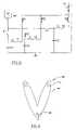
- FIG. 3is a schematic diagram of a pulse forming network with a variable pulse width for use with the skin treatment device of FIGS. 1 and 2 ;
- FIG. 4is a cross-sectional view of a coupler for coupling light from a toroidal flash tube into an optical fiber with a conical edge;
- FIG. 5is a side view of a toroidal flash tube
- FIG. 6is a top view of a toroidal flash tube
- FIG. 7shows geometry for coupling into a conical section
- FIG. 8is a cross-sectional view of a coupler for coupling light from a toroidal flash tube into an optical fiber with a flat edge;
- FIG. 9is a front sectional view of a coupler for coupling light from a linear flash tube into a circular fiber bundle
- FIG. 10is a side sectional view of the coupler of FIG. 9
- FIG. 11is a front view of a coupler for coupling light from a linear flash tube into an optical fiber;
- FIG. 12is a front view of a coupler for coupling light from a linear flash tube into a doped optical fiber
- FIG. 13is a schematic configuration of a gel skin interface with a transparent plate
- FIG. 14shows an angular distribution of photons penetrating without using a gel
- FIG. 15shows a light guide providing a large angular divergence
- FIG. 16shows a light guide providing a narrow angular divergence
- FIG. 17shows a spectra produced with a flashlamp current of 200 amps.
- FIG. 18shows a spectra produced with a flashlamp current of 200 amps.
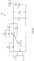
- FIG. 19shows a GTO driver circuit for a flashlamp.
- FIG. 20is a schematic drawing of a cross section of a hair follicle in the dermis and a gel applied to the epidermis in accordance with the present invention
- FIG. 21is a graph showing the optical properties of the skin
- FIG. 22is a side view of a hair removal apparatus constructed in accordance with the present invention.
- FIG. 23is a front view of a hair removal apparatus constructed in accordance with the present invention.
- FIG. 24is a divergent coupler such as one used in the present invention.
- FIG. 25is a non-divergent coupler such as one used in the present invention.
- FIGS. 1 and 2cross-sectional and side views of an incoherent, pulsed light source skin treatment device 10 constructed and operated in accordance with the principles of the present invention are shown.
- the device 10may be seen to include a housing 12 , having an opening therein, a handle 13 ( FIG. 2 only), a light source 14 having an outer glass tube 15 , an elliptical reflector 16 , a set of optical filters 18 , an iris 20 and a detector 22 ( FIG. 1 only).
- Light source 14which is mounted in housing 12 , may be a typical incoherent light source such as a gas filled linear flashlamp Model No. L5568 available from ILC.
- the spectrum of light emitted by gas filled linear flashlamp 14depends on current density, type of glass envelope material and gas mixture used in the tube. For large current densities (e.g. 3000 A/Cm2 or more) the spectrum is similar to a black body radiation spectrum. Typically, most of the energy is emitted in the 300 to 1000 nm wavelength range.
- FIG. 1shows a cross-section view of reflector 16 , also mounted in housing 12 .
- the cross-section of reflector 16 in a plane that is perpendicular to the axis of flashlamp 14is an ellipse.
- Linear flashlamp 14is located at one focus of the ellipse and reflector 16 is positioned in such a way that the treatment area of skin 21 is located at the other focus.
- the arrangement shownis similar to focusing arrangements used with lasers and efficiently couples light from flashlamp 14 to the skin. This arrangement should not, however, be considered limiting.
- Elliptical reflector 16may be a metallic reflector, typically polished aluminum which is an easily machinable reflector and has a very high reflectivity in the visible, and the UV range of the spectrum can be used. Other bare or coated metals can also be used for this purpose.
- Optical and neutral density filters 18are mounted in housing 12 near the treatment area and may be moved into the beam or out of the beam to control the spectrum and intensity of the light.
- the bandwidth filters and the cutoff filtersare readily available commercially.
- Glass tube 15is located coaxially with flashlamp 14 and has fluorescent material deposited on it. Glass tube 15 will typically be used for treatment of coagulation of blood vessels to optimize the energy efficiency of device 10 .
- the fluorescent materialcan be chosen to absorb the UV portion of the spectrum of flashlamp 14 and generate light in the 500 to 650 nm range that is optimized for absorption in the blood. Similar materials are coated on the inner walls of commercial fluorescent lamps.
- a typical material used to generate “warm” white light in fluorescent lampshas a conversion efficiency of 80%, has a peak emission wavelength of 570 nm and has a bandwidth of 70 nm and is useful for absorption in blood. The few millisecond decay time of these phosphors is consistent with long pulses that are required for the treatment of blood vessels.
- flashlamp 14such as circular, helical, short arc and multiple linear flashlamps may be used.
- Reflector 16may have other designs such as parabolic or circular reflectors.
- the light sourcecan also be used without a reflector and the required energy and power density may be achieved by locating light source 14 in close proximity to the treatment area.
- Iris 20is mounted in housing 12 between optical filters 18 and the treatment area and controls the length and the width of the exposed area, i.e. by collimating the output of flashlamp 14 .
- the length of flashlamp 14controls the maximum length that can be exposed.
- an 8 cm long (arc length) tubewill be used and only the central 5 cm of the tube is exposed. Using the central 5 cm assures a high degree of uniformity of energy density in the exposed skin area.
- the iris 20also called a collimator
- the iris 20may be closed to provide a minimum exposure length of one millimeter.
- the width of the exposed skin areacan controlled in the range of 1 to 5 mm for a 5 mm wide flashlamp. Larger exposed areas can be easily achieved by using longer flash tubes or multiple tubes, and smaller exposure areas are obtainable with an iris that more completely collimates the beam.
- the present inventionprovides a larger exposure area compared to prior art lasers or point sources and is very effective in the coagulation of blood vessels since blood flow interruption over a longer section of the vessel is more effective in coagulating it. The larger area exposed simultaneously also reduces the required procedure time.
- Detector 22( FIG. 1 ) is mounted outside housing 12 and monitors the light reflected from the skin. Detector 22 combined with optical filters 18 and neutral density filters can be used to achieve a quick estimate of the spectral reflection and absorption coefficients of the skin. This may be carried out at a low energy density level prior to the application of the main treatment pulse. Measurement of the optical properties of the skin prior to the application of the main pulse is useful to determine optimal treatment conditions. As stated above, the wide spectrum of the light emitted from the non-laser type source enables investigation of the skin over a wide spectral range and choice of optimal treatment wavelengths.
- detector 22 or a second detector systemmay be used for real-time temperature measurement of the skin during its exposure to the pulsed light source. This is useful for skin thermolysis applications with long pulses in which light is absorbed in the epidermis and dermis. When the external portion of the epidermis reaches too high a temperature, permanent scarring of the skin may result. Thus, the temperature of the skin should be measured. This can be realized using infra-red emission of the heated skin, to prevent over-exposure.
- a typical real-time detector systemwould measure the infra-red emission of the skin at two specific wavelengths by using two detectors and filters. The ratio between the signals of the two detectors can be used to estimate the instantaneous skin temperature. The operation of the pulsed light source can be stopped if a pre-selected skin temperature is reached. This measurement is relatively easy since the temperature threshold for pulsed heating, that may cause skin scarring is on the order of 50° C. or more, which is easily measurable using infra-red emission.
- Equation 1the depth of heat penetration can be controlled by the pulse-width of the light source.
- a variation of pulse-width in the range of 10 ⁇ 5 sec to 10 ⁇ 1 secwill result in a variation in the thermal penetration by a factor of 100.
- the flashlamp 14provides a pulse width of from 10–5 sec to 10–1 sec.
- the pulse lengthis chosen to uniformly heat as much of the entire thickness of the vessel as possible to achieve efficient coagulation.
- Typical blood vessels that need to be treated in the skinhave thicknesses in the range of 0.5 mm.
- the optimal pulse-widthtaking into account the thermal properties of blood, is on the order of 100 msec. If shorter pulses are used, heat will still be conducted through the blood to cause coagulation, however, the instantaneous temperature of part of the blood in the vessel and surrounding tissue will be higher than the temperature required for coagulation and may cause unwanted damage.
- a very short pulse-widthis used to provide for very shallow thermal penetration of the skin.
- a 10–5 sec pulsewill penetrate (by thermal conductivity) a depth of the order of only 5 microns into the skin.
- a very high, instantaneous temperatureis obtained so that the external mark on the skin is evaporated.
- FIG. 3shows a variable pulse-width pulse forming circuit comprised of a plurality of individual pulse forming networks (PFN's) that create the variation in pulse widths of flashlamp 14 .
- PFN'spulse forming networks
- Flashlamp 14may be driven by three different PFN'S, as shown in FIG. 3 .
- the relay contacts R 1 ′, R 2 ′ and R 3 ′are used to select among three capacitors C 1 , C 2 and C 3 that are charged by the high voltage power supply.
- Relays R 1 , R 2 and R 3are used to select the PFN that will be connected to flashlamp 14 .
- the high voltage switches S 1 , S 2 and S 3are used to discharge the energy stored in the capacitor of the PFN into flashlamp 14 .
- L 1 L 2 and L 3have values of 100 mH, 1 mH and 5 mH, respectively, and C 1 , C 2 and C 3 have values of 100 mF, 1 mF and 10 mF, respectively.
- the charging power supplytypically has a voltage range of 500 V to 5 kV.
- the relaysshould therefore be high voltage relays that can isolate these voltages reliably.
- the switches Sare capable of carrying the current of flashlamp 14 and to isolate the reverse high voltage generated if the PFNs are sequentially fired. Solid-state switches, vacuum switches or gas switches can be used for this purpose.
- a simmer power supply(not shown in FIG. 3 ) may be used to keep the flashlamp in a low current conducting mode.
- Other configurationscan be used to achieve pulse-width variation, such as the use of a single PFN and a crowbar switch, or use of a switch with closing and opening capabilities.
- a linear electrical energy density input of 100 to 300 J/cmcan be used for operation of flashlamp 14 with an electrical pulse-width of 1 to 10 msec.
- An energy density of 30 to 100 J/cm2can be achieved on the skin for a typical flashlamp bore diameter of 5 mm.
- the use of a 500 to 650 mm bandwidthtransmits 20% of the incident energy.
- energy densities on the skin of 6 to 20 J/cm2are achieved.
- the incorporation of the fluorescent materialwill further extend the output radiation in the desired range, enabling the same exposure of the skin with a lower energy input into flashlamp 14 .
- Pulsed laser skin treatmentshows that energy densities in the range of 0.5 to 10 J/cm 2 with pulse-widths in the range of 0.5 msec are generally effective for treating vascular related skin disorders. This range of parameters falls in the range of operation of pulsed non-laser type light sources such as the linear flashlamp. A few steps of neutral density glass filters 18 can also be used to control the energy density on the skin.
- Device 10can be provided as two units: a lightweight unit held by a physician using handle 13 , with the hand-held unit containing flashlamp 14 , filters 18 and iris 20 that together control the spectrum and the size of the exposed area and the detectors that measure the reflectivity and the instantaneous skin temperature.
- the power supply, the PFN's and the electrical controlsare contained in a separate box (not shown) that is connected to the hand-held unit via a flexible cable. This enables ease of operation and easy access to the areas of the skin that need to be treated.
- Coupler 40includes an optical source of high intensity incoherent and isotropic pulsed light such as a linear flash tube 42 , a light reflector 44 which delivers the light energy to an optical fiber 46 .
- the latterhas a generally conical edge in the embodiment of FIG. 4 .
- Optical fiber 46transfers the light from light collection system 44 to the treatment area.
- coupler 40couples pulsed light from a flash tube into an optical fiber and has applications in medical, industrial and domestic areas.
- coupler 40may be used in material processing to rapidly heat or ablate a portion of a material being processed, or to induce a photo-chemical process.
- coupler 40may be used in a photography application to provide a flash for picture taking. Using such a coupler would allow the flash bulb to be located inside the camera, with the light transmitted to outside the camera using an optical fiber.
- coupler 40allows the use of incoherent light in many applications that coherent or incoherent light has been used in the past.
- flash tube 42has a toroidal shape, shown in FIGS. 5 and 6 , and is disposed inside reflector 44 .
- other shapessuch as a continuous helix, may be used for flash tube 42 .
- a helical tubeis more difficult to manufacture than a toroidal tube.
- flash tube 42is generally in the shape of a tours, but is not a perfect tours since the electrodes located at the end of the tours have to be connected to the power source. This does not create a significant disturbance in the circular shape of flash tube 42 , since the connection to the electrodes can be made quite small.
- Reflector 44collects and concentrates the light, and has a cross-section of substantially an ellipse, in a plane perpendicular to the minor axis of the toroidal flash tube 42 .
- the major axis of this ellipsepreferably forms a small angle with the major axis of toroidal lamp 42 .
- the exact value of the angle between the ellipse axis and the main axis of lamp 42depends on the Numerical Aperture (NA) of the optical fiber.
- NANumerical Aperture
- the toroidal flash tubeis positioned so that its minor axis coincides with the focus of the ellipse.
- the other focus of the ellipseis at the edge of optical fiber 46 .
- Reflector 44may be machined from metal with the inner surfaces polished for good reflectivity. Aluminum is a very good reflector with high reflectivity in the visible and ultraviolet wavelengths, and it may be used for this purpose. The reflector can be machined in one piece and then cut along a surface perpendicular to the main axis of the device. This will enable integration of the toroidal flash tube into the device.
- the edge of optical fiber 46is a cone with a small opening angle, so that the total area of the fiber exposed to the light from the flash tube is increased.
- FIG. 7the geometry for coupling light into a conical tip is shown. It is assumed here that the light comes from a region in space with a refractive index of n and that the conical section of the fiber (as well as the rest of the fiber core) has a refractive index of n 1 .
- the configuration shown in FIG. 4can also be used with a fluid filling the volume between the reflector and the optical fiber.
- a very convenient fluid for this purposemay be water. Water is also very effective in cooling the flashlamp if high repetition rate pulses are used. The presence of a fluid reduces the losses that are associated with glass to air transitions, such as the transition between the flashlamp envelope material and air.
- a fluidis used in the reflector volume, then its refractive index can be chosen such that all the rays trapped in the conical section are also trapped in the fiber, even if core/cladding fibers are used.
- Another way of configuring the fiber in the reflectoris by using a fiber with a flat edge. This configuration is shown in FIG. 8 and has trapping efficiency very close to the trapping efficiency of the conical edge. Many other shapes of the fiber edge, such as spherical shapes, can also be used. The configuration of the fiber edge also has an effect on the distribution of the light on the exit side of the fiber and it can be chosen in accordance with the specific application of the device.
- the devicemay be used with a variety of optical fibers. Single, or a small number of millimeter or sub-millimeter diameter fibers, will typically be used in invasive medical applications. In other applications, particularly in industrial and domestic applications, it may be preferable to use a fiber having a larger diameter, or a larger bundle of fibers, or a light guide.
- flexible or rigid light guidesare used to couple the light to the treatment area.
- Flexible light guidesmade from a bundle of quartz or other glass fibers that are fused together by heat at the edge of the bundles.
- the bundlesmay be circular, rectangular, or any other useful shape.
- Rigid light guidesmay be made from quartz, acrylic, glass, or other materials having a high degree of transparency. The material is generally highly polished on all sides.
- a typical cross section of a circular light guide for therapeutic treatmentis one mm to ten mm in diameter.
- a rectangular light guidemay be used having typical dimensions of 3 mm by 10 mm to 30 mm by 100 mm. In either case the length may be 20 to 300 mm, or as needed for the specific application.
- a rectangular light guideis used to more efficiently couple the light.
- the rectangular light guideis chosen to have a shape that matches a rectangular linear flashlamp and to match the shape of the vessel being treated.
- the light guides described abovemay be used in another alternative embodiment to control the spectrum of light delivered to the treatment area.
- Spectral controlcan be achieved by making the light guide from a material that had an absorbing dye dissolved therein.
- light transmitted by the light guidewill have a spectrum in as determined by the absorbing dye.
- a flat, discrete filtermay be added to one end (preferably the input end) of the light guide. Both of these filters are absorbing filters.
- the inventorshave found that absorbing filters produced by Schott, having Model Nos. OG515, OG550, OG570, and OG590 have suitable characteristics.
- interference filters or reflective coatings on the light guidemay be used by applying a proper optical coating to the tight guide. Again, a single discrete interference filter could also be used. Additionally, combinations of the various filters described herein, or other filters, may be used. The use of the filters described here may render the use of the filters described earlier with reference to FIG. 1 redundant.
- An alternative embodimententails the use of application specific light guides. In this way the spectra of light for various treatments can be easily controlled. According to this alternative each type of treatment will be performed with a specific light guide.
- the optical properties of the light guidewill be chosen to optimize the particular treatment.
- the wavelengths beloware particularly useful for the respective treatments:
- spectramay be used for optimal penetration. This may be accomplished by illuminating with a few pulses, each having a different spectrum.
- the first pulsecan have a spectrum that is highly absorbed in blood. This pulse will coagulate the blood, thereby changing, the optical properties of the blood, making it more absorbing in another wavelength range (preferably longer).
- a second pulsewill be more efficiently absorbed since the blood absorbs energy of a greater wavelength range.
- This principlemay be used with lasers or other light sources as well.
- a light guideis used, in one alternative embodiment, to control the angular distribution of tile light rays impinging on the skin.
- Light that impinges on the skin at large angles (relative to the perpendicular)will not penetrate very deeply into the tissue.
- light that impinges perpendicularly to the skinwill have a deeper penetration.
- a narrow divergenceis preferable for treatment requiring deep penetration is desired.
- Some treatmentmight require both shallow and deep penetration.
- FIG. 15shows a light guide 115 having an exit beam with a greater angular divergence than that of the entrance beam.
- a beam 116enters light guide 115 at a small angle, relative to the axis of light guide 115 .
- the angle, relative to the axisis much greater.
- the tapered shape of light guide 115enhances this divergence.
- FIG. 16shows a straight light guide 118 that maintains the angular distribution of the rays of light that enter into it.
- a beam 119is shown entering and exiting light guide 118 with the same angle, relative to the axis of the coupler.
- Alternate use of both light guides 115 and 118can achieve the narrow and deep penetration discussed above.
- the usercan select the type of coupler according to the depth of penetration needed for the treatment being performed.
- FIGS. 9 and 10show a coupler 90 for coupling a linear flash tube 92 through a linear to circular fiber transfer unit 94 to a fiber bundle 96 .
- a reflector 98has an elliptical cross-section, shown in FIG. 10 , in a plane parallel to the axis of linear flash tube 92 in this embodiment.
- Tube 92is located on one focus of the ellipse while the linear side of linear to circular bundle converter is located at the other focus of the ellipse.
- This configurationis relatively simple to manufacture and commercially available linear to circular converters such as 25-004-4 available from General Fiber Optics may be used. This configuration is particularly useful for larger exposure areas of the fiber, or for flash illumination purposes.
- the energy and power densities that can be achieved by this inventionare high enough to get the desired effects in surface treatment or medical applications.
- the total energy and power densitiescan be estimated as follows.
- a typical toroidal lamp with a 4 mm bore diameter and a major diameter of 3.3 cman electrical linear energy density input of 10 J/cm into the lamp can be used with a 5 ⁇ sec pulse width.
- the light output of the lampwill be 5 to 6 J/cm for optimal electrical operating conditions.
- 50% of the light generated in the lampwill reach the lower focus.
- a total energy flux on the focus of 25 to 30 Jmay be obtained.
- the total cross-section area of reflector at the focal planehas a cross-section of 0.8 cm 2 .
- Energy densities on the order of 30 to 40 J/cm 2 at the entrance to the fibershould be attained with this cross-section. This corresponds to power densities of 5 to 10 MW/cm 2 , which are typical power densities used in medical or material processing applications.
- FIGS. 11 and 12Alternative embodiments for coupling the optical fiber to an extended light source such as a linear flashlamp are shown in FIGS. 11 and 12 .
- an optical fiber 101is wound around a lamp 102 and a lamp envelope 103 . Some of the light that is produced by the light source is coupled onto the fiber. If the light rays are propagating in the direction that is trapped by the fiber then this light will propagate in the fiber and it can be used at a fiber output 104 .
- One limitation of this configurationis the fact that most of the light emitted by lamp 103 travels in a direction perpendicular to the surface of lamp 103 and cannot be trapped in fiber 101 .
- a doped optical fiber 105is wound around lamp 102 and envelope 103 , rather than an undoped fiber such as fiber 101 of FIG. 11 .
- the dopantis a fluorescent material which is excited by the radiation emanating from lamp 102 and radiates light inside the fiber. This light is radiated omnidirectionally and the part of it that is within the critical angle of fiber 105 is trapped and propagates through the fiber and can be used at fiber output 104 .
- This embodimenthas the additional advantage of transferring the wavelength emitted by the lamp to a wavelength that may be more useful in some therapeutic or processing applications mentioned before.
- fluorescent material doped in the fibercan be chosen in accordance with an emission wavelength determined by the specific application of the device.
- One alternative embodimentincludes the use of a gel to couple the light to the skin. This alternative reduces heating of the outer layer of the skin (the epidermis and upper layers of the dermis).
- the gelis preferably a high viscosity water based gel and is applied to the skin before treatment, although other gels that are not necessarily water based may be used.
- a gel having a relatively high heat capacity and thermal conductivity, such as a water based gel,is preferable to enable cooling of the outer skin (the epidermis in particular). Transparency is also desirable because during treatment light passes through the transparent gel end reaches the skin.
- a gel 110is applied to the skin 21 prior to the treatment.
- a flat layer of gel on top of the skinis used since irregularities in the upper layer of the gel through which the light passes may cause scattering of the light and reduce its penetration into the skin.
- a solid, transparent, flat piece 111may be applied on top of the skin.
- the configurationis shown schematically in FIG. 13 .
- the transparent platecan be made out of glass or other transparent materials. Either the flashlamp housing or the light guides discussed above may be placed in direct contact with the transparent plate.
- the configuration of FIG. 13has the advantage of reducing the scattering of light (represented by arrows 113 ) that enters into the skin due to irregularities in the surface of the skin.
- the skinhas an index of refraction that is larger than that of the air.
- any photon that impinges on the air skin interfaceis deflected if it does not hit the skin at an incidence angle of 0°. Since the surface of the skin is irregular the angular distribution of the skin increases. This is shown schematically in FIG. 14 .
- the use of geladdresses this problem since the gel can fill irregular voids that are created by the skin structure.
- the transparent plate that covers the gel and the gel itselfwill preferably have an index of refraction that is close to that of the skin. This is relatively easy since the index of refraction of the skin is of the order of 1.4 in the visible and the near infrared. Most glasses and transparent plastics have indices of refraction that are of the order of 1.5 which is close enough.
- the index of refraction of wateris of the order of 1.34 in this range. Water based gels will have similar indices of refraction. The index can be increased by proper additives.
- the plate and gelthus act as a flat surface for the light to impinge upon. Because the gel and plate have an index of refraction close to that of the skin there is very little scattering at the gel-plate and gel-skin interfaces.
- lightis applied to the treated area in is either a long pulse or in a sequence of pulses separated by a delay.
- the delay and/or pulse lengthis preferably controlled by the operator to provide enough heat to accomplish the desired treatment but not enough heat to damage the skin.
- the epidermishas a thickness of approximately 0.1 mm and a cooling time of about 5 msec. Thus, to avoid burning delays greater than 5 msec are used.
- the spectrum of the light used for treatmentis controlled by controlling the voltage and/or current applied to the flashlamp.
- the spectrum of light produced by a flashlampis dependent on the voltage and current provided to the flashlamp.
- the input voltage and currentis selected to provide a desired treatment spectrum. The appropriate voltage and currents may be determined experimentally for each flashlamp used.
- a flashlamp current of 200 ampsproduced the spectra shown in FIG. 17 .
- the spectra of FIG. 18was produced using a flashlamp current of 380 amps.
- the spectra of FIG. 17shows a significant enhancement in the wavelength range of 800–1000 nm. Such a spectra is particularly useful for treatment of large vessels.
- the different currents and voltages used to control the output spectramay be obtained using a group or bank of capacitors that are capable of being connected in either series or parallel as part of the power source for the flashlamp.
- a series connectionwill provide a relatively high voltage and high current, thereby producing a spectra having energy in a shorter wavelength, such as 500–600 nm. Such a series connection will be more appropriate for generating shorter pulses (1 to 10 msec, e.g.) useful for treatment of smaller vessels.
- a parallel connectionprovides a lower current and voltage, and thus produces an output spectra of a longer wavelength, such as 700–1000 nm. Such a spectra is more appropriate for treatment of larger vessels and is suitable for producing longer pulses (in the range of 10–50 msec, e.g.).
- the selection of series or parallel connectionsmay be done using a relay or sets of relays.
- the pulse forming network of FIG. 3is replaced by a GTO driver circuit 121 , such as that shown in FIG. 19 .
- the driver circuit of FIG. 19uses a switch capable of being turned both on and off to control the application of power to the flashlamp. While this alternative embodiment will be described with respect to a GTO being used as the switch, other switches capable of being turned both on and off, such as IGBTS, may also be used.
- driver circuit 121includes a high voltage source 122 , a capacitor bank C 5 , an inductor L 5 , a diode D 5 , a switch GTO 1 , a diode D 6 , a diode D 7 , a resistor R 5 , a capacitor C 6 , a GTO trigger generator TR 1 , a resistor R 7 , a capacitor C 7 and a trigger generator TR 2 .
- These componentsare connected to flashlamp 14 and serve to provide the power pulses to flashlamp 14 . The duration and timing of the pulses are provided in accordance with the description herein.
- Driver 121operates in the manner described below.
- High voltage source 122is connected across capacitor bank C 5 , and charges capacitor bank C 5 to a voltage suitable for application to flashlamp 14 .
- Capacitor bank C 5may be comprised of one or more capacitors, and may be configured in the manner described above.
- flashtube trigger generator TR 2breaks down flashlamp 14 and creates a relatively low impedance channel therein. After the flashlamp breaks down, capacitor C 7 dumps current into flashlamp 14 , further creating a low impedance channel in flashlamp 14 . In this manner a pre-discharge is provided that prepares flashlamp 14 for the power pulse. Capacitor C 7 provides a small amount of current, relative to capacitor bank C 5 . Alternatively, driver circuit 121 may operate in a simmer mode, wherein the pre-discharge is not necessary.
- switch GTO 1is turned on via a pulse from GTO trigger generator TR 1 , completing the circuit between flashlamp 14 and capacitor bank C 5 .
- capacitor bank C 5discharges through flashlamp 14 .
- An inductor L 5may be provided to control the rise time of the current through flashlamp 14 .
- Inductor L 5may include an inherent resistive component, not shown.
- GTO trigger generator TR 1After a length of time determined by the desired pulse width has passed, GTO trigger generator TR 1 provides a pulse to switch GTO 1 , turning it off. A control circuit determines the timing of the trigger pulses and provides them in accordance with the desired pulse widths and delays.
- a snubber circuitcomprised of diode D 6 , resistor R 5 , and a capacitor C 6 is provided for switch GTO 1 . Also, diodes D 5 and D 7 are provided to protect switch GTO 1 from reverse voltages. Residtor R 7 is provided in parallel with flashlamp 14 to measure the leakage current of switch GTO 1 , which can in turn be used to make sure that switch GTO 1 is operating properly.
- driver circuit 121A possible addition to driver circuit 121 is to provide an SCR or other switch in parallel with capacitor bank C 5 . This allows the discharge or resetting of capacitor bank C 5 without turning on switch GTO 1 .
- Other modificationsmay be made, such as providing the circuit with a serial trigger, rather than the parallel trigger shown.
- Another modificationis to use the driver circuit with a laser rather than flashlamp 14 .
- the epidermishas a cooling time of about 5 msec, while large vessels have a longer cooling time (a 1 mm vessel has a cooling time of about 300 msec). Thus, during a pulse of duration longer than 5 msec the epidermis can cool down but the vessel will not. For example, for treatment of a large vessel (such as one having a diameter of about 1 mm a pulse of 100 msec will allow the skin to cool, but the vessel will not cool.
- the same effectmay be achieved using trains of pulses. This is useful when it is not practical to provide a single long pulse to the flashlamp.
- the delays between pulsesare selected to allow the skin to cool, but to be too short for the vessel to cool.
- larger vesselscan be treated with longer delays because they have greater cooling times.
- Small vesselscool quickly and long delays are not effective. However, they also need less energy and can be treated effectively in a single pulse.
- Typical delay timesare in the range of 20 msec to 500 msec. More specifically, delays of between 100–500 msec are effective for vessels larger than 1 mm in diameter.
- Delays of between 20–100 msecare effective for vessels between 0.5 and 1 mm in diameter. Delays of between 10–50 msec are effective for vessels between 0.1 and 0.5 mm in diameter. A single pulse having a width in the range of 1 msec to 20 msec is effective for vessels less than 0.1 mm diameter.
- delaysshould be selected according to skin pigmentation. Darker skin absorbs more energy and needs more time to cool: thus longer delays are needed. Lighter skin absorbs less energy and can accommodate shorter delays.
- microprocessorcan be used to provide the timing functions and prompt the trigger signals described above.
- the microprocessorincludes a user interface, such as a screen and keyboard, buttons, mouse, or other input device.
- the microprocessorshave information stored therein that aids in the selection of treatment parameters.
- the physicianinputs that condition into the microprocessor.
- the microprocessorresponds with suggested treatment parameters, such as 570 nm cut-off filter, a double pulse with a delay of 50 msec and a fluence of 55 j/cm 2 .
- the physiciancan alter these suggested parameters, but need not refer back to operating guidelines for suggested parameters.
- This alternativemay be used with light sources other than a flashlamp, such as UV or a pulsed laser.
- microprocessor output on the displayshows a simulation of interaction of light with skin and vascular lesions, oxygen concentration and temperature distribution in malignant tissue being illuminated for the purpose of cancer by a flashlamp, or processes occurring in skin resurfacing using infrared lasers or other sources.
- a program within the microprocessormodels interaction of light with tissue and vessels.
- Many programsmay be used to carry out the modeling, and in the preferred embodiment the following input parameters are used: light source type (flashlamp or pulsed laser e.g.); number of output curves (1–4 e.g.); skin type; vessel diameter and depth; blood type (oxy or deoxy-hemoglobin); pulse duration; delay between pulses; energy fluence; type of filter; short or long pulse mode; is a gel being used and its temperature.
- light source typeflashlamp or pulsed laser e.g.
- number of output curves(1–4 e.g.
- skin typee.g.
- vessel diameter and depthe.g.
- blood typeoxy or deoxy-hemoglobin
- pulse durationdelay between pulses
- energy fluencetype of filter
- short or long pulse modeis a gel being used and its temperature.
- the wavelengthis an input (400–1064 nm e.g.).
- the microprocessor and the screenshow the following information in one embodiment: temperature distribution in the tissue and in the vessel at the end of treatment; graphs of up to four curves to compare different light sources or treatment regime.
- the outputscould be printed rather than shown on a screen.
- routinesmay be used to implement the invention.
- ⁇ ais an absorption coefficient of dermis
- ⁇ sis a scattering coefficient of dermis
- gis the anisotropy factor which is defined as average cosine of scattering angle for one scattering event.
- ⁇is the density of tissue
- cis the specific heat
- ⁇is the heat conductivity coefficient
- a heat conductivity equationis calculated in cylindrical geometry for near vessel area, where the center of the cylinder was chosen as point with maximal temperature.
- ⁇ c ⁇ T/ ⁇⁇ 2 T/ ⁇ x 2 +1/ r ⁇ T/ ⁇ x+ ⁇ a ⁇ t
- the microprocessor or personal computercan also be used to create and store patient information in a database.
- past treatment informationsuch as condition being treated, treatment parameters, number of treatments, etc. is stored and may be recalled when the patient is again treated. This aids in providing the proper treatment to the patient.
- the databasemay include photographs of the patient's condition before and after each treatment. Again, this aids in record keeping and determining what treatments are most successful for given conditions.
- the devices and methods described hereinmay be used to treat other conditions. For example, psoriasis and warts have been successfully treated. Similarly, skin rejuvenation (treating wrinkles) should be effective.
- the inventorfurther contemplates using this invention to treat hemorrhoids, throat lesions, and gynecological problems associated with vascular malformations. In addition, hair depilation can also be effected.
- hairis removed by exposing the “hairy” area to intense, wide area, pulsed electromagnetic (light) energy.
- the energyheats the hair and coagulates the tissue around the hair and follicle without damaging the healthy skin.
- gelmeans a viscous fluid that is preferably, but not necessarily water based.
- the gelis used to cool the epidermis which is the primary location of light absorption by tissue, due to the melanin content of the epidermis.
- the gelis applied so as not to penetrate into the cavity generated by the hair follicle, and thus does not cool the hair and the hair follicle. As a result the energy is selectively applied to coagulate the hair without damaging the skin.
- a spatially dispersed field of lightbe used for treatment of the skin, in accordance with the invention.
- spatially dispersedit is intended that the field of light be spread over an extended area, as would be apparent from the term to one of ordinary skill in the art. Accordingly, any apparatus or combination of elements suitable for producing a dispersed field of light on the skin, as opposed to a narrow beam of light on the skin, can be used.
- a polychromatic light sourcesuch as a high intensity pulsed flashlamp
- a polychromatic sourcesuch as a flashlamp
- energy having a wavelength in the range of 550 to 630 nmis heavily absorbed in blood and can be used to coagulate the vessel that feeds the hair.
- longer wavelengths, in the range of 600 to 1100 nmhave a very good penetration into non-pigmented skin. This wavelength range can be used to couple to the melanin of the hair. The higher pigmentation of the hair and the hair follicle can enhance the absorption of energy by the hair.
- Flashlampsalso have the advantage of being able to illuminate a large area, thus minimizing the treatment time.
- the flashlamp combined with a proper reflectorcan deliver the required fluences to areas on the order of a few square centimeters in a single application.
- other light sourcessuch as pulsed lasers can be used as well.
- FIG. 20a schematic drawing of a cross section of a hair follicle 200 in a dermis 202 is shown.
- a gel 203 applied to an epidermis 204In the present invention, water based transparent gel 203 is applied to a large section of the skin that is covered by hair, such as hair 205 .
- Gel 203is applied to epidermis 204 and creates a thin layer on top of epidermis 204 . This layer is closely coupled to epidermis 204 and acts as a heat sink that cools epidermis 204 when light (electromagnetic energy) is applied to the area.
- lightelectromagagnetic energy
- gel 203does not penetrate into a cavity 206 formed by hair follicle 200 due to its surface tension properties and the fact that the hair is naturally covered by a thin layer of fatty material which makes it hydrophobic.
- the much higher heat diffusivity of gel 203 compared to that of air which fills cavity 206enables fast cooling of epidermis 204 , represented by arrows 207 , while hair 205 is cooled at a much slower rate.
- the cooling time— ⁇ t of an object that has typical dimensions d and diffusivity— ⁇can be written as: ⁇ t ⁇ d 2 16 ⁇
- the epidermishas typical cross dimensions of less than 0.1 mm, which is also the typical diameter of hair.
- the gelis applied, in the manner shown in FIG. 20 , over a wide area.
- the typical cooling time of the hairwill be on the order of 200 msec and that of the epidermis will be on the order of 5 msec. This difference in cooling times is due to the fact that the gel does not penetrate into the hair follicles. It is preferable to use a transparent gel since the gel acts only as a cooling agent and should not be heated by the external illumination.
- lightis applied to the treated area in either a long pulse or in a sequence of pulses separated by a delay.
- the delay and/or pulse lengthis preferably controlled by the operator to provide enough heat to remove the hair but not enough heat to damage the skin.
- the pulse length or delay between the pulsesshould be more than the cooling time of the gel covered epidermis and less than the cooling time of the hair and follicle.
- a pulse length of 50 msec if a single pulse is used or a delay of 50 msec between the pulses if a pulse sequence is usedare appropriate values.
- the spectrum of the light sourcemay be selected with reference to the absorption by the skin, by the hair and by the blood vessels feeding the hair.
- the hair folliclehas typical a depth of 1 to 2 mm. It is preferable, therefore, to use a light wavelength range that can penetrate into this depth without very high attenuation.
- FIG. 21is a graph showing the scattering, absorption and effective attenuation coefficients in fair skin dermis and the absorption coefficient of blood in the 400 to 1000 nm range. Because a wide area is illuminated, rather than a single hair, it is preferable to use a wavelength range that penetrates into the skin without being highly attenuated. The skin attenuation coefficient controls the depth of penetration of light into the skin. As may be seen in FIG. 21 wavelengths that are longer than 550 nm will be more effective to penetrate deep enough into the skin. Shorter wavelengths are less desirable because they will be highly attenuated before reaching the lower parts of the hair follicles.
- Wavelengths significantly longer than 1,000 nmare also less effective due to high absorption of infrared in water which constitutes more than 70% of skin.
- Wide area photo thermal hair removal of the present inventionpreferably uses light that can penetrate deep into the skin, since light is coupled to the hair and the hair follicles only after it penetrates though the skin. Most of the spectrum of light at wavelengths longer than 1,300 nm is heavily absorbed in water and will be less useful because it does not penetrate very deep into the skin. For example, CO 2 laser radiation in the 10,000 nm range penetrates only a few tens of microns into the skin.
- one preferred embodiment of hair remover 300includes a flashlamp 301 located in a housing 302 having a handle.
- the flashlamp 301is shown adjacent to gel 203 and hairy skin 202 / 204 / 205 .
- One flashlamp that the inventors have found effective for hair removalis described in detail in co-pending United States Patent Application For Method and Apparatus For Therapeutic Electromagnetic Treatment, Ser. No. 07/964,210, filed Oct. 20, 1992 and issued as U.S. Pat. No. 5,405,368, and incorporated herein by reference.
- the flashlamp described thereinprovides a suitable fluence and it illuminates a large area in a single pulse (on the order of 10 ⁇ 50 mm).
- Such a flashlamp 301is driven by a variable pulse width power source.
- the flashlamp 301is contained in housing 302 and the light from the flashlamp 301 is directed towards the skin by a reflector 305 that has a high reflectivity.
- filter 307that is disposed between flashlamp 301 and gel 203 .
- the filteror in an alternative embodiment, multiple filters, are used to control the spectrum generated by the light source.
- filteror band-pass filter, describes a device that allows electromagnetic energy (light) of certain wavelengths or frequencies to pass. The other wavelengths or frequencies are either partially or wholly removed.
- the operatorcan select the filter according to the skin pigmentation of the person being treated.
- a flashlampFor the embodiment using a flashlamp, one can take advantage of the spectral range typically generated by such a lamp which is in the range of 200 to 1300 nm for high pressure xenon flashlamps operated at high current densities (on the order of 1,000 to 5,000 A/cm 2 ). Since hair removal is mainly done for cosmetic reasons and is mostly important for cases of darker hair, the hair itself will absorb light in a wide spectral range in the visible and the near infrared. The shorter wavelengths generated by the flashlamp may be removed since they do not penetrate as deeply into the skin (as can be seen from FIG. 21 ).
- a long pass filterthat transmits only wavelengths longer than the cut off wavelength of the filter is used.
- a cut off wavelength of 600 nmis used in a preferred embodiment when the person being treated has fair skin.
- a cut off wavelength in the range of 700 to 800 nmis used in the preferred embodiment to treat people with dark skin.
- the filtersmay be, for example, dichroic filters or absorbing filters.
- the desired spectrumcan also be achieved by more than one filter or by band-pass filters.
- Window 308is placed on transparent water based gel 203 .
- the operatorholds hair remover 300 by handle 304 , and places it on the area of skin where treatment is desired (and gel 203 has been applied).
- Transparent window 308creates a well defined flat surface on gel 203 , through which light enters into gel 203 and into the skin.
- the operatorselects the pulse and energy fluence parameters on a control unit (not shown).
- the power and control unitare preferably housed in a separate box and will include power from a capacitor charged to a high voltage by a DC power supply, wherein the capacitor is discharged through the flashlamp.
- Hair remover 300can be connected to the power and control unit via a flexible cable that allows easy aiming of the device when aiming it to the treatment area on the patient's skin.
- Pulse length controlcan be achieved by using a few pulse forming networks that can generate different pulse widths.
- an opening 309may include a solid state opening switch that can stop the discharge at a time preset by the operator, thus controlling the pulse width.
- the operatorfires the unit by pressing a switch that can be located in a variety of locations.
- a total fluence on-the order of 10 to 100 J/cm 2will successfully remove the hair. This fluence can be determined from the requirement of reaching a high enough temperature of the hair and hair follicle, and considering the penetration of light, through the skin and into the hair and hair follicle, absorption of light in the hair and hair follicle, specific heat capacity of the hair and the hair follicle, and the cooling of the hair during the pulse by heat conductivity to the surrounding skin.
- Coupler 310transmits light from flashlamp 301 to gel 203 and to the skin.
- the couplercan be comprised of a hollow box with internally reflecting walls that act as a light guide for the light generated by flashlamp 301 , to transmit the light (electromagnetic energy) to the skin.
- Coupler 310may alternatively be made from other material, for example, a solid transparent material such as glass or acrylic in which light reflection from the walls is achieved by using total internal reflection on the side walls.
- Coupler 310is used, in one alternative embodiment, to control the angular distribution of the light rays impinging on the skin.
- Light rayswill hit the hair on the hair follicle predominantly when they are travelling in a direction perpendicular to the plane of the skin.
- a distribution of light rays that has a relatively wide angular divergence when treating shallow hairis desirable to direct a large portion of the energy to the hairs and follicles.
- a narrow divergenceis preferable when deep penetration is desired.
- both shallow and deep penetrationis obtained by a using a two stage treatment process.
- a narrow divergence beamis used first to treat the deeper hair follicles, while a high divergence beam is used to treat the top of the hair follicles.
- FIG. 24shows a coupler 501 having an exit beam with a greater angular divergence than that of the entrance beam.
- a beam 502enters coupler 501 at a small angle, relative to the axis of coupler 501 .
- the angle, relative to the axisis much greater.
- the tapered shape of coupler 501enhances this divergence.
- FIG. 25shows a straight coupler 601 , that maintains the angular distribution of the rays of light that enter into it.
- a beam 602is shown entering and exiting coupler 601 with the same angle, relative to the axis of coupler 601 .
- Alternate use of both couplers 501 and 601can achieve the narrow and deep penetration discussed above.
- the usercan select the type of coupler according to the depth of hair being treated.
Landscapes
- Physics & Mathematics (AREA)
- Health & Medical Sciences (AREA)
- Surgery (AREA)
- Optics & Photonics (AREA)
- Life Sciences & Earth Sciences (AREA)
- Engineering & Computer Science (AREA)
- Otolaryngology (AREA)
- Nuclear Medicine, Radiotherapy & Molecular Imaging (AREA)
- Electromagnetism (AREA)
- Biomedical Technology (AREA)
- Heart & Thoracic Surgery (AREA)
- Medical Informatics (AREA)
- Molecular Biology (AREA)
- Animal Behavior & Ethology (AREA)
- General Health & Medical Sciences (AREA)
- Public Health (AREA)
- Veterinary Medicine (AREA)
- Radiation-Therapy Devices (AREA)
Abstract
Description
d=4[kΔt/Cp]1/2 (Eq. 1)
- where k=heat conductivity of the material being illuminated;
- Δt=the pulse-width of the light pulse;
- C=the heat capacity of the material;
- p=density of the material.
Δt=2[LC]1/2 (Eq.2)
Sin(μcriti)=Cos(β)−[n12/n22−1]1/2Sin(β) (Eq. 3)
- arteries less than 0.1 mm in diameter—520–650 nm
- veins less than 0.1 mm in diameter—520–700 nm
- vessels between 0.1 and 1.0 mm in diameter—550–1000 nm
- larger vessels—600–1000 nm
F=F(0)exp(−x/d)
- where d=1/μeffand
μeff=[3μa(μa+μs(1−g))]1/2
- where d=1/μeffand
F(0)=F0(640/W)1/4where W is a wavelength.
∇2−κ2)φd=−Q
Q=3γs(γT+gγa)Foexp(−τ)
k2=3γaγtr
γtr=γs(1−g)+γa
γt=γa+γs
τ=∫γtds
where Fois the incident energy beam. Scattering and absorption coefficients are functions of wavelength. The total energy fluence rate is given by
φt=φd+φc
φc=Foexp(−τ)
φd=2/3γtr·φd2γsgFo/γtr=0
ρc·∂T/∂T=λ∂2T/∂x2+γaφt
with initial and boundary conditions
TT=0=36
∂T/∂xX=0=0
ρc·∂T/∂γ=λ∂2T/∂x2+1/r·∂T/∂x+γaφt
As on e skilled in the art should recognize other models may be used as well.
σt≈d216α
The epidermis has typical cross dimensions of less than 0.1 mm, which is also the typical diameter of hair. The diffusivity of water is approximately α=3×10⁻⁹m2sec−1.
Claims (31)
Priority Applications (1)
| Application Number | Priority Date | Filing Date | Title |
|---|---|---|---|
| US10/246,722US7108689B2 (en) | 1992-10-20 | 2002-09-19 | Method and apparatus for electromagnetic treatment of the skin, including hair depilation |
Applications Claiming Priority (9)
| Application Number | Priority Date | Filing Date | Title |
|---|---|---|---|
| US07/964,210US5405368A (en) | 1992-10-20 | 1992-10-20 | Method and apparatus for therapeutic electromagnetic treatment |
| US08/383,509US5626631A (en) | 1992-10-20 | 1995-02-03 | Method and apparatus for therapeutic electromagnetic treatment |
| US08/412,519US5683380A (en) | 1995-03-29 | 1995-03-29 | Method and apparatus for depilation using pulsed electromagnetic radiation |
| US08/473,532US5755751A (en) | 1992-10-20 | 1995-06-07 | Method and apparatus for therapeutic electromagnetic treatment |
| US08/477,479US5620478A (en) | 1992-10-20 | 1995-06-07 | Method and apparatus for therapeutic electromagnetic treatment |
| US08/508,129US5720772A (en) | 1992-10-20 | 1995-07-27 | Method and apparatus for therapeutic electromagnetic treatment |
| US08/912,764US6280438B1 (en) | 1992-10-20 | 1997-08-18 | Method and apparatus for electromagnetic treatment of the skin, including hair depilation |
| US09/505,998US6514243B1 (en) | 1992-10-20 | 2000-02-17 | Method and apparatus for electromagnetic treatment of the skin, including hair depilation |
| US10/246,722US7108689B2 (en) | 1992-10-20 | 2002-09-19 | Method and apparatus for electromagnetic treatment of the skin, including hair depilation |
Related Parent Applications (2)
| Application Number | Title | Priority Date | Filing Date |
|---|---|---|---|
| US09/487,338ContinuationUS6377974B1 (en) | 2000-01-19 | 2000-01-19 | Methods and apparatus for downloading a file from a server |
| US09/505,998ContinuationUS6514243B1 (en) | 1992-10-20 | 2000-02-17 | Method and apparatus for electromagnetic treatment of the skin, including hair depilation |
Publications (2)
| Publication Number | Publication Date |
|---|---|
| US20030069567A1 US20030069567A1 (en) | 2003-04-10 |
| US7108689B2true US7108689B2 (en) | 2006-09-19 |
Family
ID=27559892
Family Applications (3)
| Application Number | Title | Priority Date | Filing Date |
|---|---|---|---|
| US08/912,764Expired - LifetimeUS6280438B1 (en) | 1992-10-20 | 1997-08-18 | Method and apparatus for electromagnetic treatment of the skin, including hair depilation |
| US09/505,998Expired - Fee RelatedUS6514243B1 (en) | 1992-10-20 | 2000-02-17 | Method and apparatus for electromagnetic treatment of the skin, including hair depilation |
| US10/246,722Expired - Fee RelatedUS7108689B2 (en) | 1992-10-20 | 2002-09-19 | Method and apparatus for electromagnetic treatment of the skin, including hair depilation |
Family Applications Before (2)
| Application Number | Title | Priority Date | Filing Date |
|---|---|---|---|
| US08/912,764Expired - LifetimeUS6280438B1 (en) | 1992-10-20 | 1997-08-18 | Method and apparatus for electromagnetic treatment of the skin, including hair depilation |
| US09/505,998Expired - Fee RelatedUS6514243B1 (en) | 1992-10-20 | 2000-02-17 | Method and apparatus for electromagnetic treatment of the skin, including hair depilation |
Country Status (1)
| Country | Link |
|---|---|
| US (3) | US6280438B1 (en) |
Cited By (29)
| Publication number | Priority date | Publication date | Assignee | Title |
|---|---|---|---|---|
| US20050147137A1 (en)* | 2001-12-10 | 2005-07-07 | Inolase 2002 Ltd. | Eye safe dermatological phototherapy |
| US20050215987A1 (en)* | 2001-12-10 | 2005-09-29 | Michael Slatkine | Method and apparatus for vacuum-assisted light-based treatments of the skin |
| US20050234527A1 (en)* | 2001-12-10 | 2005-10-20 | Michael Slatkine | Method and apparatus for improving safety during exposure to a monochromatic light source |
| US20050251117A1 (en)* | 2004-05-07 | 2005-11-10 | Anderson Robert S | Apparatus and method for treating biological external tissue |
| US20060189964A1 (en)* | 2004-05-07 | 2006-08-24 | Anderson Robert S | Apparatus and method to apply substances to tissue |
| US20060259102A1 (en)* | 2001-12-10 | 2006-11-16 | Michael Slatkine | Method and apparatus for vacuum-assisted light-based treatments of the skin |
| US20070179482A1 (en)* | 2004-05-07 | 2007-08-02 | Anderson Robert S | Apparatuses and methods to treat biological external tissue |
| US7452358B2 (en) | 1996-01-05 | 2008-11-18 | Thermage, Inc. | RF electrode assembly for handpiece |
| US7473251B2 (en) | 1996-01-05 | 2009-01-06 | Thermage, Inc. | Methods for creating tissue effect utilizing electromagnetic energy and a reverse thermal gradient |
| US20090012434A1 (en)* | 2007-07-03 | 2009-01-08 | Anderson Robert S | Apparatus, method, and system to treat a volume of skin |
| US7481809B2 (en) | 1996-01-05 | 2009-01-27 | Thermage, Inc. | Handpiece with RF electrode and non-volatile memory |
| US20090059617A1 (en)* | 2007-08-27 | 2009-03-05 | Morgan Lars Ake Gustavsson | Volume emitter |
| US20090069795A1 (en)* | 2007-09-10 | 2009-03-12 | Anderson Robert S | Apparatus and method for selective treatment of tissue |
| US20090088823A1 (en)* | 2007-09-28 | 2009-04-02 | Menashe Barak | Vacuum assisted treatment of the skin |
| US20090093864A1 (en)* | 2007-10-08 | 2009-04-09 | Anderson Robert S | Methods and devices for applying energy to tissue |
| EP2234461A2 (en) | 2009-03-23 | 2010-09-29 | Lumenis Ltd. | System and method to regulate high current radiation sources |
| US7842029B2 (en) | 2004-05-07 | 2010-11-30 | Aesthera | Apparatus and method having a cooling material and reduced pressure to treat biological external tissue |
| US8685017B2 (en) | 1996-01-05 | 2014-04-01 | Thermage, Inc. | Method and kit for treatment of tissue |
| US9724160B2 (en) | 2010-10-25 | 2017-08-08 | Koninklijke Philips N.V. | Skin treatment system |
| US11865287B2 (en) | 2005-12-30 | 2024-01-09 | Hydrafacial Llc | Devices and methods for treating skin |
| US11883621B2 (en) | 2008-01-04 | 2024-01-30 | Hydrafacial Llc | Devices and methods for skin treatment |
| US11903615B2 (en) | 2013-03-15 | 2024-02-20 | Hydrafacial Llc | Devices, systems and methods for treating the skin |
| USD1016615S1 (en) | 2021-09-10 | 2024-03-05 | Hydrafacial Llc | Container for a skin treatment device |
| US11925780B2 (en) | 2014-12-23 | 2024-03-12 | Hydrafacial Llc | Devices and methods for treating the skin |
| US12005217B2 (en) | 2008-01-29 | 2024-06-11 | Hydrafacial Llc | Devices, systems and methods for skin treatment |
| USD1042807S1 (en) | 2021-10-11 | 2024-09-17 | Hydrafacial Llc | Skin treatment tip |
| USD1065551S1 (en) | 2021-09-10 | 2025-03-04 | Hydrafacial Llc | Skin treatment device |
| US12295618B2 (en) | 2020-01-06 | 2025-05-13 | Hydrafacial Llc | Skin treatment tool applicator tip |
| USD1084369S1 (en) | 2023-02-10 | 2025-07-15 | Hydrafacial Llc | Skin treatment tip |
Families Citing this family (207)
| Publication number | Priority date | Publication date | Assignee | Title |
|---|---|---|---|---|
| US6280438B1 (en)* | 1992-10-20 | 2001-08-28 | Esc Medical Systems Ltd. | Method and apparatus for electromagnetic treatment of the skin, including hair depilation |
| US7267675B2 (en) | 1996-01-05 | 2007-09-11 | Thermage, Inc. | RF device with thermo-electric cooler |
| US7189230B2 (en) | 1996-01-05 | 2007-03-13 | Thermage, Inc. | Method for treating skin and underlying tissue |
| US7006874B2 (en) | 1996-01-05 | 2006-02-28 | Thermage, Inc. | Treatment apparatus with electromagnetic energy delivery device and non-volatile memory |
| US7115123B2 (en) | 1996-01-05 | 2006-10-03 | Thermage, Inc. | Handpiece with electrode and non-volatile memory |
| US20040000316A1 (en)* | 1996-01-05 | 2004-01-01 | Knowlton Edward W. | Methods for creating tissue effect utilizing electromagnetic energy and a reverse thermal gradient |
| US7141049B2 (en)* | 1999-03-09 | 2006-11-28 | Thermage, Inc. | Handpiece for treatment of tissue |
| US7022121B2 (en) | 1999-03-09 | 2006-04-04 | Thermage, Inc. | Handpiece for treatment of tissue |
| US7204832B2 (en) | 1996-12-02 | 2007-04-17 | Pálomar Medical Technologies, Inc. | Cooling system for a photo cosmetic device |
| US20060149343A1 (en)* | 1996-12-02 | 2006-07-06 | Palomar Medical Technologies, Inc. | Cooling system for a photocosmetic device |
| US6517532B1 (en) | 1997-05-15 | 2003-02-11 | Palomar Medical Technologies, Inc. | Light energy delivery head |
| US6653618B2 (en) | 2000-04-28 | 2003-11-25 | Palomar Medical Technologies, Inc. | Contact detecting method and apparatus for an optical radiation handpiece |
| US8182473B2 (en) | 1999-01-08 | 2012-05-22 | Palomar Medical Technologies | Cooling system for a photocosmetic device |
| US5810801A (en)* | 1997-02-05 | 1998-09-22 | Candela Corporation | Method and apparatus for treating wrinkles in skin using radiation |
| ES2226133T3 (en) | 1997-05-15 | 2005-03-16 | Palomar Medical Technologies, Inc. | DERMATOLOGICAL TREATMENT DEVICE. |
| US8313480B2 (en)* | 2004-10-02 | 2012-11-20 | Joseph Neev | Device and method for treating skin disorders with thermal energy |
| US7981112B1 (en)* | 1997-08-12 | 2011-07-19 | Joseph Neev | Home use device and methods for treating skin conditions |
| ES2245506T3 (en)* | 1998-03-12 | 2006-01-01 | Palomar Medical Technologies, Inc. | ELECTROMAGNETIC RADIATION APPLICATION SYSTEM ON SKIN. |
| CA2326120C (en)* | 1998-03-27 | 2015-01-13 | The General Hospital Corporation | Method and apparatus for the selective targeting of lipid-rich tissues |
| US6595986B2 (en) | 1998-10-15 | 2003-07-22 | Stephen Almeida | Multiple pulse photo-dermatological device |
| US6219575B1 (en)* | 1998-10-23 | 2001-04-17 | Babak Nemati | Method and apparatus to enhance optical transparency of biological tissues |
| US20130274837A1 (en)* | 1998-10-23 | 2013-10-17 | Babak Nemati | Systems and Methods to Enhance Optical Transparency of Biological Tissues for Photobiomodulation |
| US6514242B1 (en)* | 1998-12-03 | 2003-02-04 | David Vasily | Method and apparatus for laser removal of hair |
| US20020156471A1 (en)* | 1999-03-09 | 2002-10-24 | Stern Roger A. | Method for treatment of tissue |
| US7041094B2 (en)* | 1999-03-15 | 2006-05-09 | Cutera, Inc. | Tissue treatment device and method |
| WO2003053266A2 (en)* | 1999-06-30 | 2003-07-03 | Thermage, Inc. | Liquid cooled rf handpiece |
| JP4495894B2 (en)* | 2000-01-25 | 2010-07-07 | パロマー・メディカル・テクノロジーズ・インコーポレーテッド | Device for medical treatment using long-term electromagnetic radiation |
| US20040005349A1 (en)* | 2000-05-12 | 2004-01-08 | Joseph Neev | Opto-thermal material modification |
| US7083610B1 (en)* | 2000-06-07 | 2006-08-01 | Laserscope | Device for irradiating tissue |
| RU2165743C1 (en)* | 2000-09-12 | 2001-04-27 | Хомченко Владимир Валентинович | Method for performing blood vessel laser coagulation |
| US6746444B2 (en)* | 2000-12-18 | 2004-06-08 | Douglas J. Key | Method of amplifying a beneficial selective skin response to light energy |
| US20080172047A1 (en)* | 2000-12-28 | 2008-07-17 | Palomar Medical Technologies, Inc. | Methods And Devices For Fractional Ablation Of Tissue |
| EP1700573A3 (en)* | 2000-12-28 | 2010-12-01 | Palomar Medical Technologies, Inc. | Apparatus for therapeutic EMR treatment of the skin |
| WO2002065871A1 (en)* | 2001-02-23 | 2002-08-29 | Koninklijke Philips Electronics N.V. | Hair removing device comprising a heating member |
| US6888319B2 (en) | 2001-03-01 | 2005-05-03 | Palomar Medical Technologies, Inc. | Flashlamp drive circuit |
| WO2002069825A2 (en)* | 2001-03-02 | 2002-09-12 | Palomar Medical Technologies, Inc. | Apparatus and method for photocosmetic and photodermatological treatment |
| DE10123926A1 (en)* | 2001-03-08 | 2002-09-19 | Optomed Optomedical Systems Gmbh | irradiation device |
| JP2002263206A (en)* | 2001-03-13 | 2002-09-17 | Seric Ltd | Phototherapy apparatus |
| US6723090B2 (en) | 2001-07-02 | 2004-04-20 | Palomar Medical Technologies, Inc. | Fiber laser device for medical/cosmetic procedures |
| US7170034B2 (en)* | 2002-02-05 | 2007-01-30 | Radiancy Inc. | Pulsed electric shaver |
| US20130041309A1 (en)* | 2001-08-23 | 2013-02-14 | Jerry Siegel | Apparatus and method for performing radiation energy treatments |
| US7160287B1 (en)* | 2001-08-23 | 2007-01-09 | Jerry Siegel | Apparatus and method for performing radiation energy treatments |
| US8287524B2 (en)* | 2001-08-23 | 2012-10-16 | Jerry Siegel | Apparatus and method for performing radiation energy treatments |
| US6733890B2 (en)* | 2001-10-23 | 2004-05-11 | Fujitsu Limited | Integrated ceramic module and microwave dielectric composition |
| ITBO20010706A1 (en)* | 2001-11-21 | 2003-05-21 | Gen Project S R L | ELECTROMEDICAL PULSED LIGHT EQUIPMENT FOR SKIN TREATMENT |
| US20040147984A1 (en)* | 2001-11-29 | 2004-07-29 | Palomar Medical Technologies, Inc. | Methods and apparatus for delivering low power optical treatments |
| WO2003103523A1 (en)* | 2002-06-06 | 2003-12-18 | Inolase 2002 Ltd. | Eye safe dermotological phototherapy |
| EP1455671B1 (en)* | 2001-12-10 | 2007-06-13 | Inolase 2002 Ltd. | Method and apparatus for improving safety during exposure to a monochromatic light source |
| US7540869B2 (en) | 2001-12-27 | 2009-06-02 | Palomar Medical Technologies, Inc. | Method and apparatus for improved vascular related treatment |
| CN1652729A (en)* | 2002-03-12 | 2005-08-10 | 帕洛玛医疗技术公司 | Method and device for treating hair growth |
| AU2003230808A1 (en)* | 2002-04-05 | 2003-10-27 | Candela Corporation | High fluence rate activation of photosensitizers for dermatological applications |
| US7056318B2 (en)* | 2002-04-12 | 2006-06-06 | Reliant Technologies, Inc. | Temperature controlled heating device and method to heat a selected area of a biological body |
| GB0210302D0 (en)* | 2002-05-07 | 2002-06-12 | Siden Ltd | Improvements in and relating to intense pulsed light devices |
| JP2003325684A (en)* | 2002-05-17 | 2003-11-18 | Iryo Joho Kaihatsu Kenkyusho:Kk | Phototherapy device |
| US20070239142A1 (en)* | 2006-03-10 | 2007-10-11 | Palomar Medical Technologies, Inc. | Photocosmetic device |
| WO2004000098A2 (en)* | 2002-06-19 | 2003-12-31 | Palomar Medical Technologies, Inc. | Method and apparatus for treatment of cutaneous and subcutaneous conditions |
| CA2487987C (en) | 2002-06-19 | 2010-04-13 | Palomar Medical Technologies, Inc. | Method and apparatus for photothermal treatment of tissue at depth |
| US7740600B2 (en)* | 2002-08-02 | 2010-06-22 | Candela Corporation | Apparatus and method for inhibiting pain signals transmitted during a skin related medical treatment |
| US20040034397A1 (en)* | 2002-08-14 | 2004-02-19 | Lin J. T. | Method and apparatus for treating skin disorders using a short pulsed incoherent light |
| US20040126272A1 (en)* | 2002-08-28 | 2004-07-01 | Eric Bornstein | Near infrared microbial elimination laser system |
| US20040156743A1 (en)* | 2002-08-28 | 2004-08-12 | Eric Bornstein | Near infrared microbial elimination laser system |
| WO2007014130A2 (en)* | 2005-07-21 | 2007-02-01 | Nomir Medical Technologies, Inc. | Near infrared microbial elimination laser system (nimels) |
| US20080131968A1 (en)* | 2002-08-28 | 2008-06-05 | Nomir Medical Technologies, Inc. | Near-infrared electromagnetic modification of cellular steady-state membrane potentials |
| US7713294B2 (en) | 2002-08-28 | 2010-05-11 | Nomir Medical Technologies, Inc. | Near infrared microbial elimination laser systems (NIMEL) |
| US8506979B2 (en) | 2002-08-28 | 2013-08-13 | Nomir Medical Technologies, Inc. | Near-infrared electromagnetic modification of cellular steady-state membrane potentials |
| JP2006501960A (en)* | 2002-10-07 | 2006-01-19 | パロマー・メディカル・テクノロジーズ・インコーポレイテッド | Apparatus for photobiological stimulation |
| US20070219605A1 (en)* | 2006-03-20 | 2007-09-20 | Palomar Medical Technologies, Inc. | Treatment of tissue volume with radiant energy |
| EP2522294A2 (en) | 2002-10-23 | 2012-11-14 | Palomar Medical Technologies, Inc. | Phototreatment device for use with coolants and topical substances |
| US7699058B1 (en) | 2002-11-08 | 2010-04-20 | Jay Harvey H | Hair treatment method |
| US7931028B2 (en)* | 2003-08-26 | 2011-04-26 | Jay Harvey H | Skin injury or damage prevention method using optical radiation |
| US6824542B2 (en) | 2002-11-08 | 2004-11-30 | Harvey H. Jay | Temporary hair removal method |
| US6916316B2 (en)* | 2002-11-08 | 2005-07-12 | Harvey H. Jay | Hair treatment method |
| WO2004047921A1 (en) | 2002-11-28 | 2004-06-10 | Koninklijke Philips Electronics N.V. | Device for treating human skin by means of radiation |
| US7255560B2 (en)* | 2002-12-02 | 2007-08-14 | Nomir Medical Technologies, Inc. | Laser augmented periodontal scaling instruments |
| US7041109B2 (en)* | 2002-12-12 | 2006-05-09 | Kelsey, Inc. | Apparatus and method for interstitial laser therapy of small breast cancers and adjunctive therapy |
| US6981970B2 (en)* | 2002-12-16 | 2006-01-03 | Msq (M2) Ltd. | Device and method for treating skin |
| AU2003301111A1 (en)* | 2002-12-20 | 2004-07-22 | Palomar Medical Technologies, Inc. | Apparatus for light treatment of acne and other disorders of follicles |
| US20040147985A1 (en)* | 2003-01-27 | 2004-07-29 | Altus Medical, Inc. | Dermatological treatment flashlamp device and method |
| US20050177141A1 (en)* | 2003-01-27 | 2005-08-11 | Davenport Scott A. | System and method for dermatological treatment gas discharge lamp with controllable current density |
| EP1599147A2 (en)* | 2003-02-19 | 2005-11-30 | Palomar Medical Technologies, Inc. | Method and apparatus for treating pseudofolliculitis barbae |
| US7703458B2 (en)* | 2003-02-21 | 2010-04-27 | Cutera, Inc. | Methods and devices for non-ablative laser treatment of dermatologic conditions |
| ES2570987T3 (en) | 2003-02-25 | 2016-05-23 | Tria Beauty Inc | Dermatological treatment device, based on diode laser and autonomous |
| WO2004075976A2 (en) | 2003-02-25 | 2004-09-10 | Spectragenics, Inc. | Method and apparatus for the treatment of benign pigmented lesions |
| US7250045B2 (en) | 2003-02-25 | 2007-07-31 | Spectragenics, Inc. | Self-contained, eye-safe hair-regrowth-inhibition apparatus and method |
| WO2004075718A2 (en) | 2003-02-25 | 2004-09-10 | Spectragenics, Inc. | Eye-safe dermatologic treatment apparatus and method |
| US8709003B2 (en) | 2003-02-25 | 2014-04-29 | Tria Beauty, Inc. | Capacitive sensing method and device for detecting skin |
| EP2604216B1 (en)* | 2003-02-25 | 2018-08-22 | Tria Beauty, Inc. | Self-contained, diode-laser-based dermatologic treatment apparatus |
| US7413567B2 (en) | 2003-02-25 | 2008-08-19 | Spectragenics, Inc. | Optical sensor and method for identifying the presence of skin |
| WO2004078034A2 (en)* | 2003-03-04 | 2004-09-16 | Spectragenics, Inc. | Method and apparatus for the repigmentation of human skin |
| EP1611814A1 (en)* | 2003-03-13 | 2006-01-04 | Radiancy Inc. | Electric shaver with vibrating head |
| JP2006514566A (en)* | 2003-03-13 | 2006-05-11 | レイディアンシー インク. | Heat shaving electric shaver with removable head |
| AU2003212644A1 (en)* | 2003-03-13 | 2004-09-30 | Zion Azar | Electric shaver with heated cutting element and with deodorant dispenser |
| ITBO20030261A1 (en)* | 2003-05-02 | 2004-11-03 | Michael Magri | LUMINOUS RADIATION UNIT FOR DIAGNOSIS AND TREATMENT OF SKIN PROBLEMS. |
| US7470124B2 (en)* | 2003-05-08 | 2008-12-30 | Nomir Medical Technologies, Inc. | Instrument for delivery of optical energy to the dental root canal system for hidden bacterial and live biofilm thermolysis |
| US7284080B2 (en)* | 2003-07-07 | 2007-10-16 | Sigmatel, Inc. | Memory bus assignment for functional devices in an audio/video signal processing system |
| US7291140B2 (en) | 2003-07-18 | 2007-11-06 | Cutera, Inc. | System and method for low average power dermatologic light treatment device |
| EP1658113B1 (en)* | 2003-08-18 | 2013-01-23 | Koninklijke Philips Electronics N.V. | Device for low intensity optical hair growth control |
| US7722600B2 (en) | 2003-08-25 | 2010-05-25 | Cutera, Inc. | System and method for heating skin using light to provide tissue treatment |
| US8870856B2 (en) | 2003-08-25 | 2014-10-28 | Cutera, Inc. | Method for heating skin using light to provide tissue treatment |
| US8915906B2 (en) | 2003-08-25 | 2014-12-23 | Cutera, Inc. | Method for treatment of post-partum abdominal skin redundancy or laxity |
| US7544204B2 (en)* | 2003-10-15 | 2009-06-09 | Valam Corporation | Control of halitosis-generating and other microorganisms in the non-dental upper respiratory tract |
| RU2250119C1 (en)* | 2003-10-30 | 2005-04-20 | Борисов Владимир Алексеевич | Device for applying electromagnetic treatment to biological tissue |
| ITBO20030717A1 (en) | 2003-11-27 | 2005-05-28 | Espansione Marketing S P A | LIGHT IRRADIATION UNIT. |
| US7326199B2 (en) | 2003-12-22 | 2008-02-05 | Cutera, Inc. | System and method for flexible architecture for dermatologic treatments utilizing multiple light sources |
| US20050143792A1 (en)* | 2003-12-24 | 2005-06-30 | Harvey Jay | Hair treatment method |
| US7309335B2 (en) | 2003-12-31 | 2007-12-18 | Palomar Medical Technologies, Inc. | Dermatological treatment with visualization |
| US20050177140A1 (en)* | 2004-02-06 | 2005-08-11 | Harvey Jay | Pulsed light treatment apparatus and associated method with preliminary light pulse generation |
| US8777935B2 (en) | 2004-02-25 | 2014-07-15 | Tria Beauty, Inc. | Optical sensor and method for identifying the presence of skin |
| EP2301471A1 (en) | 2004-04-01 | 2011-03-30 | The General Hospital Corporation | Method and apparatus for dermatological treatment and tissue reshaping |
| JP2008500846A (en)* | 2004-04-09 | 2008-01-17 | パロマー メディカル テクノロジーズ,インク. | Method and product for making a grid of EMR-treated isolated points in tissue and use thereof |
| USD557403S1 (en)* | 2004-05-27 | 2007-12-11 | Moritex Corporation | Facial skin observation device |
| USD548326S1 (en)* | 2004-05-27 | 2007-08-07 | Moritex Corporation | Facial skin observation device |
| USD547437S1 (en)* | 2004-05-27 | 2007-07-24 | Moritex Corporation | Facial skin observation device |
| ES2317003T3 (en)* | 2004-07-06 | 2009-04-16 | Radiancy Inc. | ELECTRIC TRASURADORA UNDERSTANDING AN ELEMENT THAT ELIMINATES THE REMAINS AND ITS USE. |
| CN101052325A (en)* | 2004-07-06 | 2007-10-10 | 雷蒂安西公司 | Electric shaver able to reheat hair |
| MX2007000270A (en)* | 2004-07-06 | 2007-04-02 | Radiancy Inc | Improved electric shaver. |
| US7837675B2 (en) | 2004-07-22 | 2010-11-23 | Shaser, Inc. | Method and device for skin treatment with replaceable photosensitive window |
| JP2008508034A (en)* | 2004-07-27 | 2008-03-21 | バイオレーズ テクノロジー インコーポレイテッド | Contra-angle rotating handpiece with tactile feedback tip ferrule |
| US7970030B2 (en)* | 2004-07-27 | 2011-06-28 | Biolase Technology, Inc. | Dual pulse-width medical laser with presets |
| US20060047281A1 (en) | 2004-09-01 | 2006-03-02 | Syneron Medical Ltd. | Method and system for invasive skin treatment |
| US20060093561A1 (en)* | 2004-11-02 | 2006-05-04 | John Kennedy | Method of treating microorganisms in the oral cavity |
| BRPI0519217A2 (en)* | 2004-12-22 | 2009-01-06 | Gillette Co | Reduction of hair growth with survivin inhibitors |
| CA2590328A1 (en)* | 2004-12-22 | 2006-06-29 | The Gillette Company | Reduction of hair growth |
| EP1827280A2 (en)* | 2004-12-22 | 2007-09-05 | The Gillette Company | Reduction of hair growth |
| US20110015549A1 (en)* | 2005-01-13 | 2011-01-20 | Shimon Eckhouse | Method and apparatus for treating a diseased nail |
| US8277495B2 (en) | 2005-01-13 | 2012-10-02 | Candela Corporation | Method and apparatus for treating a diseased nail |
| US7291141B2 (en)* | 2005-02-02 | 2007-11-06 | Jay Harvey H | Method and apparatus for enhancing hair removal |
| CN101132831A (en)* | 2005-02-18 | 2008-02-27 | 帕洛玛医疗技术公司 | Dermatological treatment device |
| US20060253176A1 (en)* | 2005-02-18 | 2006-11-09 | Palomar Medical Technologies, Inc. | Dermatological treatment device with deflector optic |
| WO2006092776A1 (en)* | 2005-03-03 | 2006-09-08 | Leortec Ltd. | Aesthetic treatment device |
| US20060200114A1 (en)* | 2005-03-04 | 2006-09-07 | Searete Llc, A Limited Liability Corporation Of State Of Delaware | Hair removal system with light source array |
| US8679101B2 (en)* | 2005-03-04 | 2014-03-25 | The Invention Science Fund I, Llc | Method and system for temporary hair removal |
| US8540701B2 (en)* | 2005-03-04 | 2013-09-24 | The Invention Science Fund I, Llc | Hair treatment system |
| US20060276859A1 (en)* | 2005-06-02 | 2006-12-07 | Searete Llc, A Limited Liability Corporation Of The State Of Delaware | Photopatterning of skin |
| US8157807B2 (en)* | 2005-06-02 | 2012-04-17 | The Invention Science Fund I, Llc | Skin treatment including patterned light |
| US8529560B2 (en) | 2005-03-04 | 2013-09-10 | The Invention Science Fund I, Llc | Hair treatment system |
| US7856985B2 (en) | 2005-04-22 | 2010-12-28 | Cynosure, Inc. | Method of treatment body tissue using a non-uniform laser beam |
| US20070032846A1 (en)* | 2005-08-05 | 2007-02-08 | Bran Ferren | Holographic tattoo |
| US9055958B2 (en)* | 2005-06-29 | 2015-06-16 | The Invention Science Fund I, Llc | Hair modification using converging light |
| US20070038270A1 (en)* | 2005-07-05 | 2007-02-15 | Searete Llc, A Limited Liability Corporation Of The State Of Delaware | Multi step photopatterning of skin |
| JP2009502406A (en) | 2005-08-05 | 2009-01-29 | コーニンクレッカ フィリップス エレクトロニクス エヌ ヴィ | Skin treatment equipment |
| US20070048340A1 (en)* | 2005-08-31 | 2007-03-01 | Searete Llc, A Limited Liability Corporation Of The State Of Delaware | Multi step patterning of a skin surface |
| CN101309631A (en) | 2005-09-15 | 2008-11-19 | 帕洛玛医疗技术公司 | Skin optical characterization device |
| WO2007038567A1 (en) | 2005-09-28 | 2007-04-05 | Candela Corporation | Treating cellulite |
| CA113237S (en) | 2005-10-26 | 2009-07-15 | John Kennedy | Phototherapy device |
| JP4687436B2 (en)* | 2005-12-13 | 2011-05-25 | ウシオ電機株式会社 | Excimer light therapy device |
| US7891362B2 (en) | 2005-12-23 | 2011-02-22 | Candela Corporation | Methods for treating pigmentary and vascular abnormalities in a dermal region |
| WO2007087374A2 (en)* | 2006-01-24 | 2007-08-02 | Nomir Medical Technologies, Inc. | Optical method and device for modulation of biochemical processes in adipose tissue |
| CA2535276A1 (en)* | 2006-02-06 | 2007-08-06 | John Kennedy | Therapy device and system and method for reducing harmful exposure to electromagnetic radiation |
| US20070194717A1 (en)* | 2006-02-17 | 2007-08-23 | Palomar Medical Technologies, Inc. | Lamp for use in a tissue treatment device |
| WO2007099546A2 (en)* | 2006-03-03 | 2007-09-07 | Alma Lasers Ltd. | Method and apparatus for light-based hair removal using incoherent light pulses |
| CA2644512C (en)* | 2006-03-03 | 2016-08-02 | Alma Lasers Ltd. | Method and apparatus for light-based hair removal |
| US20080031833A1 (en)* | 2006-03-13 | 2008-02-07 | Oblong John E | Combined energy and topical composition application for regulating the condition of mammalian skin |
| US20070271714A1 (en)* | 2006-03-17 | 2007-11-29 | Light Dimensions, Inc. | Light-based enhancing apparatuses and methods of use |
| WO2007117580A2 (en)* | 2006-04-06 | 2007-10-18 | Palomar Medical Technologies, Inc. | Apparatus and method for skin treatment with compression and decompression |
| US8460280B2 (en)* | 2006-04-28 | 2013-06-11 | Cutera, Inc. | Localized flashlamp skin treatments |
| US8753334B2 (en) | 2006-05-10 | 2014-06-17 | Covidien Ag | System and method for reducing leakage current in an electrosurgical generator |
| US8246611B2 (en) | 2006-06-14 | 2012-08-21 | Candela Corporation | Treatment of skin by spatial modulation of thermal heating |
| US7586957B2 (en) | 2006-08-02 | 2009-09-08 | Cynosure, Inc | Picosecond laser apparatus and methods for its operation and use |
| US20080045933A1 (en)* | 2006-08-15 | 2008-02-21 | Paul Perl | Multi-broadband pulse emitter and a method for applying an effective dermal treatment |
| US20080055755A1 (en)* | 2006-08-31 | 2008-03-06 | Searete Llc, A Limited Liability Corporation Of The State Of Delaware | Electromagnetic device and method |
| US20080082091A1 (en)* | 2006-09-10 | 2008-04-03 | Vladimir Rubtsov | Fiber optic tissue ablation |
| USD585997S1 (en) | 2006-10-13 | 2009-02-03 | Light Dimensions, Inc. | Light-based dermal enhancing apparatus |
| US20100324544A1 (en)* | 2006-10-23 | 2010-12-23 | Koninklijke Philips Electronics N.V. | Optical treatment system and an adjustment member therefor |
| US20080186591A1 (en)* | 2007-02-01 | 2008-08-07 | Palomar Medical Technologies, Inc. | Dermatological device having a zoom lens system |
| US9849304B2 (en)* | 2007-08-02 | 2017-12-26 | Gustavsson Nevada Holding Llc | Device and method for treatment of organic tissue |
| US8920409B2 (en)* | 2007-10-04 | 2014-12-30 | Cutera, Inc. | System and method for dermatological lesion treatment using gas discharge lamp with controllable current density |
| US20090112063A1 (en)* | 2007-10-31 | 2009-04-30 | Bakos Gregory J | Endoscopic overtubes |
| FR2924597B1 (en)* | 2007-12-10 | 2014-06-13 | Oreal | PROCESS FOR TREATING KERATIN FIBERS HAVING THEIR EXPOSURE TO LOW-LIFE LIGHT PULSES |
| US9155905B2 (en) | 2008-01-16 | 2015-10-13 | Morgan Lars Ake Gustavsson | Fluorescent handpiece |
| US8465532B2 (en) | 2008-01-16 | 2013-06-18 | Morgan Lars Ake Gustavsson | Fluorescent handpiece |
| US7955367B2 (en) | 2008-01-16 | 2011-06-07 | Morgan Gustavsson | Fluorescent handpiece |
| MX2010007860A (en) | 2008-01-17 | 2010-11-30 | Syneron Medical Ltd | A hair removal apparatus for personal use and the method of using same. |
| EP2237732A4 (en) | 2008-01-24 | 2011-06-01 | Syneron Medical Ltd | A device, apparatus, and method of adipose tissue treatment |
| US20090306636A1 (en)* | 2008-02-06 | 2009-12-10 | Hai Ben-Israel | Dermal treatment device |
| EP2471481B2 (en) | 2008-03-07 | 2023-03-22 | Koninklijke Philips N.V. | Photo-epilation device |
| EP2258301A3 (en)* | 2008-03-11 | 2013-04-17 | Shaser, Inc. | Enhancing optical radiation systems used in dermatologic treatments |
| FR2929831B1 (en)* | 2008-04-10 | 2011-09-02 | Eurofeedback Sa | DEVICE FOR PROCESSING BY TRANSMITTING LIGHT FLASKS |
| WO2009132355A1 (en) | 2008-04-25 | 2009-10-29 | Tria Beauty, Inc. | Optical sensor and method for identifying the presence of skin and the pigmentation of skin |
| US20100017750A1 (en)* | 2008-07-16 | 2010-01-21 | Avner Rosenberg | User interface |
| US9314293B2 (en)* | 2008-07-16 | 2016-04-19 | Syneron Medical Ltd | RF electrode for aesthetic and body shaping devices and method of using same |
| FR2934951B1 (en)* | 2008-08-18 | 2011-10-28 | Michel Trezon | PROFESSIONAL DEVICE FOR DEPILATING AND PHOTOGALLING BY PULSE MONOBLOCK LIGHT, AUTONOMOUS AND MINIATURIZED |
| EP2334249B1 (en) | 2008-09-21 | 2013-03-13 | Syneron Medical Ltd. | A method and apparatus for personal skin treatment |
| US20100211055A1 (en)* | 2009-02-18 | 2010-08-19 | Shimon Eckhouse | Method for body toning and an integrated data management system for the same |
| US8606366B2 (en) | 2009-02-18 | 2013-12-10 | Syneron Medical Ltd. | Skin treatment apparatus for personal use and method for using same |
| EP2730313A1 (en) | 2009-02-25 | 2014-05-14 | Syneron Medical Ltd. | Electrical skin rejuvenation |
| GB2470927A (en)* | 2009-06-10 | 2010-12-15 | Dezac Group Ltd | Phototherapy apparatus with skin temperature control |
| US9919168B2 (en) | 2009-07-23 | 2018-03-20 | Palomar Medical Technologies, Inc. | Method for improvement of cellulite appearance |
| IL201369A0 (en)* | 2009-10-11 | 2010-05-31 | Michael Slatkine | A bermatology apparatus |
| EP2506773B1 (en)* | 2009-12-06 | 2018-08-15 | Syneron Medical Ltd. | Apparatus for personal skin treatment |
| KR101339402B1 (en)* | 2011-05-25 | 2013-12-09 | 주식회사 칼라세븐 | Color light therapy device |
| JP6022560B2 (en)* | 2011-06-22 | 2016-11-09 | ラディアンシー インク. | Hair loss and hair growth inhibiting device |
| SE535834C2 (en)* | 2011-07-14 | 2013-01-08 | Profoto Ab | A flash tube with an outer trigger wire |
| EP2839552A4 (en) | 2012-04-18 | 2015-12-30 | Cynosure Inc | PICOSECOND LASER APPARATUS AND METHOD OF PROCESSING TARGET TISSUES USING THE SAME |
| JP2014161455A (en)* | 2013-02-22 | 2014-09-08 | Panasonic Corp | Cosmetic apparatus for hair |
| US10285757B2 (en) | 2013-03-15 | 2019-05-14 | Cynosure, Llc | Picosecond optical radiation systems and methods of use |
| EP3202351B1 (en) | 2016-02-02 | 2021-08-25 | Braun GmbH | Skin treatment device |
| IL303752A (en)* | 2016-06-24 | 2023-08-01 | Lumenis Be Ltd | Selective skin treatments using strong laser-like light beam devices |
| US11813474B2 (en)* | 2016-06-24 | 2023-11-14 | Lumenis Be Ltd. | Cosmetic method and apparatus for selecting an IPL light source having a band pass filter equivalent to a specified wavelength laser light source for providing cosmetic treatment of skin tissue |
| WO2019150359A1 (en)* | 2018-02-05 | 2019-08-08 | Shterzer Moshe | Intense pulse light (ipl) apparatus utilizing a pulse forming network (pfn) |
| WO2019165426A1 (en) | 2018-02-26 | 2019-08-29 | Cynosure, Inc. | Q-switched cavity dumped sub-nanosecond laser |
| EP3613376A1 (en) | 2018-08-21 | 2020-02-26 | Koninklijke Philips N.V. | A handheld device for performing a treatment operation on skin |
| JP7228814B2 (en)* | 2019-11-07 | 2023-02-27 | パナソニックIpマネジメント株式会社 | Hair cutting device and hair cutting system |
| EP3915502A1 (en)* | 2020-05-28 | 2021-12-01 | Koninklijke Philips N.V. | Apparatus for providing visual guidance for a user of a personal care device |
| EP4514257B1 (en)* | 2022-04-28 | 2025-09-03 | Koninklijke Philips N.V. | Treatment device for performing light-based treatment operations |
| EP4268753A1 (en)* | 2022-04-28 | 2023-11-01 | Koninklijke Philips N.V. | Treatment device for performing light-based treatment operations |
| CN117547348B (en)* | 2023-12-13 | 2024-10-15 | 深圳市爱诗恩科技有限公司 | Dehairing instrument for generating ultra-long pulse width strong pulse light and implementation method thereof |
Citations (84)
| Publication number | Priority date | Publication date | Assignee | Title |
|---|---|---|---|---|
| US1651385A (en) | 1925-07-13 | 1927-12-06 | Sanitarium And Hospital Equipm | Portable therapeutic lamp |
| CH416861A (en) | 1962-09-25 | 1966-07-15 | Kern & Sprenger Kom Ges Dr | Arrangement for adjusting the intensity of a light beam |
| US3327712A (en) | 1961-09-15 | 1967-06-27 | Ira H Kaufman | Photocoagulation type fiber optical surgical device |
| US3538919A (en) | 1967-04-07 | 1970-11-10 | Gregory System Inc | Depilation by means of laser energy |
| US3693623A (en) | 1970-12-25 | 1972-09-26 | Gregory System Inc | Photocoagulation means and method for depilation |
| US3818914A (en) | 1972-04-17 | 1974-06-25 | Spectroderm Inc | Apparatus and method for treatment of skin disorders |
| US3821510A (en) | 1973-02-22 | 1974-06-28 | H Muncheryan | Hand held laser instrumentation device |
| US3834391A (en) | 1973-01-19 | 1974-09-10 | Block Carol Ltd | Method and apparatus for photoepilation |
| US3916143A (en) | 1971-04-22 | 1975-10-28 | Research Corp | Branding living animals |
| US4022534A (en) | 1976-03-23 | 1977-05-10 | Kollmorgen Corporation | Reflectometer optical system |
| DE2717421A1 (en) | 1974-05-21 | 1978-11-16 | Nath Guenther | Coagulator producing haemostasis or destruction of tissue - using incandescent lamp filament to heat probe pressed against flesh |
| JPS55117166A (en) | 1979-03-02 | 1980-09-09 | Ushio Inc | Lighting device |
| US4229658A (en) | 1978-08-18 | 1980-10-21 | Dentsply Research & Development Corp. | Xenon light apparatus for supplying ultraviolet and visible spectra |
| US4233493A (en) | 1974-05-21 | 1980-11-11 | Nath Guenther | Apparatus for applying intense light radiation to a limited area |
| US4241382A (en) | 1979-03-23 | 1980-12-23 | Maurice Daniel | Fiber optics illuminator |
| SE416861B (en) | 1974-11-28 | 1981-02-09 | Bbc Brown Boveri & Cie | CLUTCH FOR REACTIVE POWER SAVING RECTIFICATION |
| US4283661A (en) | 1980-02-25 | 1981-08-11 | Battle Creek Equipment Co. | Irradiation device and removable timer useful therewith |
| US4298005A (en) | 1976-03-05 | 1981-11-03 | Mutzhas Maximilian F | Radiation apparatus |
| EP0052765A1 (en) | 1980-11-24 | 1982-06-02 | Maximilian F. Prof. Dr. Mutzhas | Device for the phototherapeutical treatment of hyperbilirubenemia |
| US4388924A (en) | 1981-05-21 | 1983-06-21 | Weissman Howard R | Method for laser depilation |
| AU1851583A (en) | 1982-08-27 | 1984-03-01 | Alistair Joseph Blake | Lamp for irradiating tumours |
| DE3330293A1 (en) | 1983-08-23 | 1985-03-14 | Alfred 7500 Karlsruhe Frank | Use of a laser light beam for reducing wrinkling of the skin or for improving or restoring hair growth |
| JPS60132571A (en) | 1983-12-19 | 1985-07-15 | 澁谷工業株式会社 | Treatment of dermatophytosis |
| US4539987A (en) | 1980-02-27 | 1985-09-10 | Nath Guenther | Apparatus for coagulation by heat radiation |
| FR2571264A1 (en) | 1984-10-04 | 1986-04-11 | Navarro Christian | Device emitting laser beams for medical use |
| US4608978A (en) | 1983-09-26 | 1986-09-02 | Carol Block Limited | Method and apparatus for photoepiltion |
| US4617926A (en) | 1982-07-09 | 1986-10-21 | Sutton A Gunilla | Depilation device and method |
| US4669466A (en) | 1985-01-16 | 1987-06-02 | Lri L.P. | Method and apparatus for analysis and correction of abnormal refractive errors of the eye |
| US4686986A (en) | 1981-09-02 | 1987-08-18 | Marta Fenyo | Method and apparatus for promoting healing |
| US4754381A (en) | 1986-01-02 | 1988-06-28 | Downs James W | Ellipsoidal reflector concentration of energy system |
| US4757431A (en) | 1986-07-01 | 1988-07-12 | Laser Media | Off-axis application of concave spherical reflectors as condensing and collecting optics |
| US4784135A (en) | 1982-12-09 | 1988-11-15 | International Business Machines Corporation | Far ultraviolet surgical and dental procedures |
| US4792341A (en) | 1986-06-19 | 1988-12-20 | Clairol Incorporated | Hair photobleaching |
| US4810658A (en)* | 1984-06-13 | 1989-03-07 | Ares-Serono Research & Development | Photometric instruments, their use in methods of optical analysis, and ancillary devices therefor |
| US4829262A (en) | 1984-10-25 | 1989-05-09 | Candela Laser Corporation | Long pulse tunable light amplifier |
| EP0324490A2 (en) | 1988-01-15 | 1989-07-19 | SAUNALUX GMBH PRODUCTS & CO KG | Large surface irradiation device |
| US4858090A (en) | 1987-06-26 | 1989-08-15 | Downs James W | Ellipsoidal reflector concentration of energy system |
| US4860172A (en) | 1988-01-19 | 1989-08-22 | Biotronics Associates, Inc. | Lamp-based laser simulator |
| DE3804732A1 (en) | 1988-02-15 | 1989-08-24 | Oka Kano & Oehmichen Kg Forsch | Device for focusing electromagnetic radiation |
| DE3906860A1 (en) | 1988-03-08 | 1989-09-28 | Fraunhofer Ges Forschung | DEVICE FOR PRODUCING ANGIOGRAPHY |
| US4874361A (en) | 1986-12-29 | 1989-10-17 | Obagi Zein E | Method for healing damaged skin |
| US4897771A (en) | 1987-11-24 | 1990-01-30 | Lumitex, Inc. | Reflector and light system |
| US4930504A (en) | 1987-11-13 | 1990-06-05 | Diamantopoulos Costas A | Device for biostimulation of tissue and method for treatment of tissue |
| DE8900871U1 (en) | 1989-01-26 | 1990-06-07 | Coffee Team Kaffeemaschinen GmbH, 7187 Schrozberg | Dosing device |
| JPH02154753A (en) | 1988-08-11 | 1990-06-14 | Morita Mfg Co Ltd | Variable radiation angle laser irradiation device |
| US4940922A (en) | 1985-12-16 | 1990-07-10 | Ilc Technology, Inc. | Integral reflector flashlamp |
| US4947305A (en) | 1989-05-19 | 1990-08-07 | Vector Technical Group, Inc. | Lamp reflector |
| US4950880A (en) | 1989-07-28 | 1990-08-21 | Recon/Optical, Inc. | Synthetic aperture optical imaging system |
| US4974138A (en) | 1983-08-19 | 1990-11-27 | Masataka Negishi | Lighting device |
| US5057104A (en) | 1989-05-30 | 1991-10-15 | Cyrus Chess | Method and apparatus for treating cutaneous vascular lesions |
| WO1991015264A1 (en) | 1990-04-09 | 1991-10-17 | Morgan Gustafsson | Device for treatment of undesired skin disfigurements |
| US5109463A (en) | 1990-06-25 | 1992-04-28 | Lee Ho Shang | Fiber optic lamp |
| JPH04506312A (en) | 1989-06-30 | 1992-11-05 | レーザー バイオテック,インコーポレイテッド | Method and device for contracting collagen tissue |
| US5161526A (en) | 1989-04-04 | 1992-11-10 | Hellwing Isak A | Method of treating of bleeding in hemophiliacs |
| US5207671A (en) | 1991-04-02 | 1993-05-04 | Franken Peter A | Laser debridement of wounds |
| US5217455A (en) | 1991-08-12 | 1993-06-08 | Tan Oon T | Laser treatment method for removing pigmentations, lesions, and abnormalities from the skin of a living human |
| US5226907A (en) | 1991-10-29 | 1993-07-13 | Tankovich Nikolai I | Hair removal device and method |
| EP0565331A2 (en) | 1992-04-09 | 1993-10-13 | ESC Medical Systems Ltd. | Therapeutic electromagnetic treatment |
| US5259380A (en) | 1987-11-04 | 1993-11-09 | Amcor Electronics, Ltd. | Light therapy system |
| US5265598A (en) | 1990-08-27 | 1993-11-30 | Energy Spectrum Foundation | Phototherapy method |
| US5300097A (en) | 1991-02-13 | 1994-04-05 | Lerner Ethan A | Fiber optic psoriasis treatment device |
| US5330517A (en) | 1991-04-22 | 1994-07-19 | Institut National De La Sante Et De La Recherche Medicale | Device for treating tissue by pulse sequence group |
| US5337741A (en) | 1991-06-21 | 1994-08-16 | Diamond Donald A | Photo radiation treatment apparatus and method |
| US5344434A (en) | 1991-12-29 | 1994-09-06 | Technion Research & Development Foundation, Ltd. | Apparatus for the photodynamic therapy treatment |
| US5344418A (en) | 1991-12-12 | 1994-09-06 | Shahriar Ghaffari | Optical system for treatment of vascular lesions |
| US5394307A (en) | 1992-06-08 | 1995-02-28 | Olympus Optical Co., Ltd. | Photographic flash device |
| US5405368A (en) | 1992-10-20 | 1995-04-11 | Esc Inc. | Method and apparatus for therapeutic electromagnetic treatment |
| US5414600A (en) | 1993-07-30 | 1995-05-09 | Cogent Light Technologies, Inc. | Condensing and collecting optical system using an ellipsoidal reflector |
| US5425728A (en) | 1991-10-29 | 1995-06-20 | Tankovich; Nicolai I. | Hair removal device and method |
| US5441531A (en) | 1993-10-18 | 1995-08-15 | Dusa Pharmaceuticals Inc. | Illuminator and methods for photodynamic therapy |
| US5511563A (en) | 1991-06-21 | 1996-04-30 | Diamond; Donald A. | Apparatus and method for treating rheumatoid and psoriatic arthritis |
| US5527350A (en) | 1993-02-24 | 1996-06-18 | Star Medical Technologies, Inc. | Pulsed infrared laser treatment of psoriasis |
| EP0724894A2 (en) | 1995-02-03 | 1996-08-07 | ESC Medical Systems Ltd. | Method and apparatus for therapeutic electromagnetic treatment |
| US5560699A (en) | 1993-09-02 | 1996-10-01 | General Electric Company | Optical coupling arrangement between a lamp and a light guide |
| EP0736308A2 (en) | 1995-03-29 | 1996-10-09 | ESC Medical Systems Ltd. | Method and apparatus for depilation using pulsed electromagnetic radiation |
| US5595568A (en) | 1995-02-01 | 1997-01-21 | The General Hospital Corporation | Permanent hair removal using optical pulses |
| US5606798A (en) | 1991-03-12 | 1997-03-04 | Kelman; Elliot | Hair cutting apparatus |
| US5620478A (en) | 1992-10-20 | 1997-04-15 | Esc Medical Systems Ltd. | Method and apparatus for therapeutic electromagnetic treatment |
| US5707403A (en) | 1993-02-24 | 1998-01-13 | Star Medical Technologies, Inc. | Method for the laser treatment of subsurface blood vessels |
| US5720772A (en) | 1992-10-20 | 1998-02-24 | Esc Medical Systems Ltd. | Method and apparatus for therapeutic electromagnetic treatment |
| US5735844A (en) | 1995-02-01 | 1998-04-07 | The General Hospital Corporation | Hair removal using optical pulses |
| US5843143A (en) | 1992-10-23 | 1998-12-01 | Cancer Research Campaign Technology Ltd. | Light source |
| US5885273A (en) | 1995-03-29 | 1999-03-23 | Esc Medical Systems, Ltd. | Method for depilation using pulsed electromagnetic radiation |
| US6280438B1 (en) | 1992-10-20 | 2001-08-28 | Esc Medical Systems Ltd. | Method and apparatus for electromagnetic treatment of the skin, including hair depilation |
Family Cites Families (2)
| Publication number | Priority date | Publication date | Assignee | Title |
|---|---|---|---|---|
| WO1989000871A1 (en) | 1987-07-24 | 1989-02-09 | Katona Belane | Apparatus for irradiating by polarised light |
| JPH07187687A (en) | 1993-12-27 | 1995-07-25 | Nippon Electric Glass Co Ltd | Production of hollow glass article and device therefor |
- 1997
- 1997-08-18USUS08/912,764patent/US6280438B1/ennot_activeExpired - Lifetime
- 2000
- 2000-02-17USUS09/505,998patent/US6514243B1/ennot_activeExpired - Fee Related
- 2002
- 2002-09-19USUS10/246,722patent/US7108689B2/ennot_activeExpired - Fee Related
Patent Citations (92)
| Publication number | Priority date | Publication date | Assignee | Title |
|---|---|---|---|---|
| US1651385A (en) | 1925-07-13 | 1927-12-06 | Sanitarium And Hospital Equipm | Portable therapeutic lamp |
| US3327712A (en) | 1961-09-15 | 1967-06-27 | Ira H Kaufman | Photocoagulation type fiber optical surgical device |
| CH416861A (en) | 1962-09-25 | 1966-07-15 | Kern & Sprenger Kom Ges Dr | Arrangement for adjusting the intensity of a light beam |
| US3538919A (en) | 1967-04-07 | 1970-11-10 | Gregory System Inc | Depilation by means of laser energy |
| US3693623A (en) | 1970-12-25 | 1972-09-26 | Gregory System Inc | Photocoagulation means and method for depilation |
| US3916143A (en) | 1971-04-22 | 1975-10-28 | Research Corp | Branding living animals |
| US3818914A (en) | 1972-04-17 | 1974-06-25 | Spectroderm Inc | Apparatus and method for treatment of skin disorders |
| US3834391A (en) | 1973-01-19 | 1974-09-10 | Block Carol Ltd | Method and apparatus for photoepilation |
| US3821510A (en) | 1973-02-22 | 1974-06-28 | H Muncheryan | Hand held laser instrumentation device |
| DE2717421A1 (en) | 1974-05-21 | 1978-11-16 | Nath Guenther | Coagulator producing haemostasis or destruction of tissue - using incandescent lamp filament to heat probe pressed against flesh |
| US4233493A (en) | 1974-05-21 | 1980-11-11 | Nath Guenther | Apparatus for applying intense light radiation to a limited area |
| SE416861B (en) | 1974-11-28 | 1981-02-09 | Bbc Brown Boveri & Cie | CLUTCH FOR REACTIVE POWER SAVING RECTIFICATION |
| US4298005A (en) | 1976-03-05 | 1981-11-03 | Mutzhas Maximilian F | Radiation apparatus |
| US4022534A (en) | 1976-03-23 | 1977-05-10 | Kollmorgen Corporation | Reflectometer optical system |
| US4229658A (en) | 1978-08-18 | 1980-10-21 | Dentsply Research & Development Corp. | Xenon light apparatus for supplying ultraviolet and visible spectra |
| JPS55117166A (en) | 1979-03-02 | 1980-09-09 | Ushio Inc | Lighting device |
| US4241382A (en) | 1979-03-23 | 1980-12-23 | Maurice Daniel | Fiber optics illuminator |
| US4283661A (en) | 1980-02-25 | 1981-08-11 | Battle Creek Equipment Co. | Irradiation device and removable timer useful therewith |
| US4539987A (en) | 1980-02-27 | 1985-09-10 | Nath Guenther | Apparatus for coagulation by heat radiation |
| EP0052765A1 (en) | 1980-11-24 | 1982-06-02 | Maximilian F. Prof. Dr. Mutzhas | Device for the phototherapeutical treatment of hyperbilirubenemia |
| US4388924A (en) | 1981-05-21 | 1983-06-21 | Weissman Howard R | Method for laser depilation |
| US4686986A (en) | 1981-09-02 | 1987-08-18 | Marta Fenyo | Method and apparatus for promoting healing |
| US4617926A (en) | 1982-07-09 | 1986-10-21 | Sutton A Gunilla | Depilation device and method |
| AU1851583A (en) | 1982-08-27 | 1984-03-01 | Alistair Joseph Blake | Lamp for irradiating tumours |
| US4784135A (en) | 1982-12-09 | 1988-11-15 | International Business Machines Corporation | Far ultraviolet surgical and dental procedures |
| US4974138A (en) | 1983-08-19 | 1990-11-27 | Masataka Negishi | Lighting device |
| DE3330293A1 (en) | 1983-08-23 | 1985-03-14 | Alfred 7500 Karlsruhe Frank | Use of a laser light beam for reducing wrinkling of the skin or for improving or restoring hair growth |
| US4608978A (en) | 1983-09-26 | 1986-09-02 | Carol Block Limited | Method and apparatus for photoepiltion |
| JPS60132571A (en) | 1983-12-19 | 1985-07-15 | 澁谷工業株式会社 | Treatment of dermatophytosis |
| US4810658A (en)* | 1984-06-13 | 1989-03-07 | Ares-Serono Research & Development | Photometric instruments, their use in methods of optical analysis, and ancillary devices therefor |
| FR2571264A1 (en) | 1984-10-04 | 1986-04-11 | Navarro Christian | Device emitting laser beams for medical use |
| US5066293A (en) | 1984-10-25 | 1991-11-19 | Candela Laser Corporation | Light amplifier and method of photothemolysis |
| US4829262A (en) | 1984-10-25 | 1989-05-09 | Candela Laser Corporation | Long pulse tunable light amplifier |
| US4669466A (en) | 1985-01-16 | 1987-06-02 | Lri L.P. | Method and apparatus for analysis and correction of abnormal refractive errors of the eye |
| US4940922A (en) | 1985-12-16 | 1990-07-10 | Ilc Technology, Inc. | Integral reflector flashlamp |
| US4754381A (en) | 1986-01-02 | 1988-06-28 | Downs James W | Ellipsoidal reflector concentration of energy system |
| US4792341A (en) | 1986-06-19 | 1988-12-20 | Clairol Incorporated | Hair photobleaching |
| US4757431A (en) | 1986-07-01 | 1988-07-12 | Laser Media | Off-axis application of concave spherical reflectors as condensing and collecting optics |
| US4874361A (en) | 1986-12-29 | 1989-10-17 | Obagi Zein E | Method for healing damaged skin |
| US4858090A (en) | 1987-06-26 | 1989-08-15 | Downs James W | Ellipsoidal reflector concentration of energy system |
| US5259380A (en) | 1987-11-04 | 1993-11-09 | Amcor Electronics, Ltd. | Light therapy system |
| US4930504A (en) | 1987-11-13 | 1990-06-05 | Diamantopoulos Costas A | Device for biostimulation of tissue and method for treatment of tissue |
| US4897771A (en) | 1987-11-24 | 1990-01-30 | Lumitex, Inc. | Reflector and light system |
| EP0324490A2 (en) | 1988-01-15 | 1989-07-19 | SAUNALUX GMBH PRODUCTS & CO KG | Large surface irradiation device |
| US4860172A (en) | 1988-01-19 | 1989-08-22 | Biotronics Associates, Inc. | Lamp-based laser simulator |
| DE3804732A1 (en) | 1988-02-15 | 1989-08-24 | Oka Kano & Oehmichen Kg Forsch | Device for focusing electromagnetic radiation |
| DE3906860A1 (en) | 1988-03-08 | 1989-09-28 | Fraunhofer Ges Forschung | DEVICE FOR PRODUCING ANGIOGRAPHY |
| JPH02154753A (en) | 1988-08-11 | 1990-06-14 | Morita Mfg Co Ltd | Variable radiation angle laser irradiation device |
| DE8900871U1 (en) | 1989-01-26 | 1990-06-07 | Coffee Team Kaffeemaschinen GmbH, 7187 Schrozberg | Dosing device |
| US5161526A (en) | 1989-04-04 | 1992-11-10 | Hellwing Isak A | Method of treating of bleeding in hemophiliacs |
| US4947305A (en) | 1989-05-19 | 1990-08-07 | Vector Technical Group, Inc. | Lamp reflector |
| US5282797A (en) | 1989-05-30 | 1994-02-01 | Cyrus Chess | Method for treating cutaneous vascular lesions |
| US5057104A (en) | 1989-05-30 | 1991-10-15 | Cyrus Chess | Method and apparatus for treating cutaneous vascular lesions |
| JPH04506312A (en) | 1989-06-30 | 1992-11-05 | レーザー バイオテック,インコーポレイテッド | Method and device for contracting collagen tissue |
| US4950880A (en) | 1989-07-28 | 1990-08-21 | Recon/Optical, Inc. | Synthetic aperture optical imaging system |
| SE465953B (en) | 1990-04-09 | 1991-11-25 | Morgan Gustafsson | DEVICE FOR TREATMENT OF UNDESECTED EXTERNAL ACCOMMODATIONS |
| WO1991015264A1 (en) | 1990-04-09 | 1991-10-17 | Morgan Gustafsson | Device for treatment of undesired skin disfigurements |
| US5320618A (en) | 1990-04-09 | 1994-06-14 | Morgan Gustafsson | Device for treatment of undesired skin disfigurements |
| US5109463A (en) | 1990-06-25 | 1992-04-28 | Lee Ho Shang | Fiber optic lamp |
| US5265598A (en) | 1990-08-27 | 1993-11-30 | Energy Spectrum Foundation | Phototherapy method |
| US5300097A (en) | 1991-02-13 | 1994-04-05 | Lerner Ethan A | Fiber optic psoriasis treatment device |
| US5606798A (en) | 1991-03-12 | 1997-03-04 | Kelman; Elliot | Hair cutting apparatus |
| US5207671A (en) | 1991-04-02 | 1993-05-04 | Franken Peter A | Laser debridement of wounds |
| US5330517A (en) | 1991-04-22 | 1994-07-19 | Institut National De La Sante Et De La Recherche Medicale | Device for treating tissue by pulse sequence group |
| US5337741A (en) | 1991-06-21 | 1994-08-16 | Diamond Donald A | Photo radiation treatment apparatus and method |
| US5511563A (en) | 1991-06-21 | 1996-04-30 | Diamond; Donald A. | Apparatus and method for treating rheumatoid and psoriatic arthritis |
| US5217455A (en) | 1991-08-12 | 1993-06-08 | Tan Oon T | Laser treatment method for removing pigmentations, lesions, and abnormalities from the skin of a living human |
| US5226907A (en) | 1991-10-29 | 1993-07-13 | Tankovich Nikolai I | Hair removal device and method |
| US5425728A (en) | 1991-10-29 | 1995-06-20 | Tankovich; Nicolai I. | Hair removal device and method |
| US5344418A (en) | 1991-12-12 | 1994-09-06 | Shahriar Ghaffari | Optical system for treatment of vascular lesions |
| USRE36634E (en) | 1991-12-12 | 2000-03-28 | Ghaffari; Shahriar | Optical system for treatment of vascular lesions |
| US5344434A (en) | 1991-12-29 | 1994-09-06 | Technion Research & Development Foundation, Ltd. | Apparatus for the photodynamic therapy treatment |
| EP0565331A2 (en) | 1992-04-09 | 1993-10-13 | ESC Medical Systems Ltd. | Therapeutic electromagnetic treatment |
| US5394307A (en) | 1992-06-08 | 1995-02-28 | Olympus Optical Co., Ltd. | Photographic flash device |
| US5620478A (en) | 1992-10-20 | 1997-04-15 | Esc Medical Systems Ltd. | Method and apparatus for therapeutic electromagnetic treatment |
| US6514243B1 (en)* | 1992-10-20 | 2003-02-04 | Lumenis Ltd. | Method and apparatus for electromagnetic treatment of the skin, including hair depilation |
| US6280438B1 (en) | 1992-10-20 | 2001-08-28 | Esc Medical Systems Ltd. | Method and apparatus for electromagnetic treatment of the skin, including hair depilation |
| US5626631A (en) | 1992-10-20 | 1997-05-06 | Esc Medical Systems Ltd. | Method and apparatus for therapeutic electromagnetic treatment |
| US5405368A (en) | 1992-10-20 | 1995-04-11 | Esc Inc. | Method and apparatus for therapeutic electromagnetic treatment |
| US5720772A (en) | 1992-10-20 | 1998-02-24 | Esc Medical Systems Ltd. | Method and apparatus for therapeutic electromagnetic treatment |
| US5843143A (en) | 1992-10-23 | 1998-12-01 | Cancer Research Campaign Technology Ltd. | Light source |
| US5527350A (en) | 1993-02-24 | 1996-06-18 | Star Medical Technologies, Inc. | Pulsed infrared laser treatment of psoriasis |
| US5707403A (en) | 1993-02-24 | 1998-01-13 | Star Medical Technologies, Inc. | Method for the laser treatment of subsurface blood vessels |
| US5414600A (en) | 1993-07-30 | 1995-05-09 | Cogent Light Technologies, Inc. | Condensing and collecting optical system using an ellipsoidal reflector |
| US5560699A (en) | 1993-09-02 | 1996-10-01 | General Electric Company | Optical coupling arrangement between a lamp and a light guide |
| US5441531A (en) | 1993-10-18 | 1995-08-15 | Dusa Pharmaceuticals Inc. | Illuminator and methods for photodynamic therapy |
| US5595568A (en) | 1995-02-01 | 1997-01-21 | The General Hospital Corporation | Permanent hair removal using optical pulses |
| US5735844A (en) | 1995-02-01 | 1998-04-07 | The General Hospital Corporation | Hair removal using optical pulses |
| EP0724894A2 (en) | 1995-02-03 | 1996-08-07 | ESC Medical Systems Ltd. | Method and apparatus for therapeutic electromagnetic treatment |
| US5885273A (en) | 1995-03-29 | 1999-03-23 | Esc Medical Systems, Ltd. | Method for depilation using pulsed electromagnetic radiation |
| US5683380A (en) | 1995-03-29 | 1997-11-04 | Esc Medical Systems Ltd. | Method and apparatus for depilation using pulsed electromagnetic radiation |
| EP0736308A2 (en) | 1995-03-29 | 1996-10-09 | ESC Medical Systems Ltd. | Method and apparatus for depilation using pulsed electromagnetic radiation |
Non-Patent Citations (23)
| Title |
|---|
| Anderson, Rox, and Parrish, John, "Selective Photothermolysis: Precise Microsurgery by Selective Absorption of Pulsed Radiation," Science (1989). |
| Declaration of Alon Maor in Support of Plaintiffs's Motion for Preliminary Injunction (Apr. 25, 2003). |
| Declaration of Benjamin J. Fox in Opposition to Plaintiffs' Motion for a Preliminary Injunction (May 7, 2003). |
| Declaration of Dr. Michael Kreindel in Opposition to Motion for Preliminary Injunction (May 6, 2003). |
| Declaration of Dr. Warren S. Grundfest in Support of Syneron's Opposition to Plainfitts' Motion for Preliminary Injunction (May 6, 2003). |
| Declaration of Felix T. Woo in Support of Plaintiffs' Motion for Preliminary Injunction (May 19, 2003). |
| Declaration of Harry F. Manbeck, Jr. in Response to Expert Report of Gerald J. Mossinghoff (May 23, 2003). |
| Declaration of Moshe Mizrahy in Opposition to Plaintiffs' Motion for a Preliminary Injunction (May 6, 2003). |
| Diffusion of Light in Turbid Material, A. Ishimaru, Applied Optics 1989, vol. 28, No. 12, pp. 2210-2215. |
| Expert Opinion of Dr. Joseph T. Walsh, Jr. in Support of Plaintiffs' Motion for Preliminary Injunction (Apr. 25, 2003). |
| Expert Report of Hon. Gerald J. Mossinghoff in Support of Plaintiffs' Motion for Preliminary Injunction (May 19, 2003). |
| Gustafsson et al. "A Variable Pulsewidth Vascular System for Dermatology", SPIE vol. 2128, pp. 186-196 (1994). |
| Lahaye et al. "Optimal Laser Parameters for Port Wine Stain Therapy: A Theoretical Approach", Phys. Med. Biol., 1985, vol. 30, pp. 573 to 587 (1985). |
| Notice of Recent Decision by European Patent Office Revoking the European Counterpart to the '368 Patent (May 23, 2003). |
| Notice of Response of Court-Appointed Expert to Order Seeking Clarification (Jun. 13, 2003). |
| Plaintiffs' Memorandum of Points and Authorities in Support of Motion for Preliminary Injunction (Apr. 25, 2003). |
| Plaintiff's Motion for Preliminary Injunction (Jul. 11, 2003). |
| Plaintiffs' Notice of Lodging Opinion and Tutorial of Court Appointed Expert Dr. Oscar M. Stafsudd (Apr. 25, 2003). |
| Reply of Plaintiffs Lumenis Ltd. And Lumenis Inc. in Support of Motion for Preliminary Injunction (May 19, 2003). |
| Reply Opinion of Joseph T. Walsh, Jr. in Support of Plaintiffs' Motion for Preliminary Injunction (May 19, 2003). |
| Supplemental Declaration of Alon Maor in Support of Plaintiff Lumenis, Inc.'s Motion for Preliminary Injunction (May 19, 2003). |
| Syneron's Memorandum of Points and Authorities in Opposition to Plaintiffs' Motion for a Preliminary Injunction (May 7, 2003). |
| Van-Gemert et al. "Treatment of Port-Wine Stains: Analysis", Medical Instrumentation, vol. 21, pp. 213-217 (1987). |
Cited By (45)
| Publication number | Priority date | Publication date | Assignee | Title |
|---|---|---|---|---|
| US7452358B2 (en) | 1996-01-05 | 2008-11-18 | Thermage, Inc. | RF electrode assembly for handpiece |
| US8685017B2 (en) | 1996-01-05 | 2014-04-01 | Thermage, Inc. | Method and kit for treatment of tissue |
| US7481809B2 (en) | 1996-01-05 | 2009-01-27 | Thermage, Inc. | Handpiece with RF electrode and non-volatile memory |
| US7473251B2 (en) | 1996-01-05 | 2009-01-06 | Thermage, Inc. | Methods for creating tissue effect utilizing electromagnetic energy and a reverse thermal gradient |
| US20060259102A1 (en)* | 2001-12-10 | 2006-11-16 | Michael Slatkine | Method and apparatus for vacuum-assisted light-based treatments of the skin |
| US20050215987A1 (en)* | 2001-12-10 | 2005-09-29 | Michael Slatkine | Method and apparatus for vacuum-assisted light-based treatments of the skin |
| US7762964B2 (en) | 2001-12-10 | 2010-07-27 | Candela Corporation | Method and apparatus for improving safety during exposure to a monochromatic light source |
| US7762965B2 (en) | 2001-12-10 | 2010-07-27 | Candela Corporation | Method and apparatus for vacuum-assisted light-based treatments of the skin |
| US20090299440A9 (en)* | 2001-12-10 | 2009-12-03 | Michael Slatkine | Method and apparatus for improving safety during exposure to a monochromatic light source |
| US20100246619A9 (en)* | 2001-12-10 | 2010-09-30 | Inolase 2002 Ltd. | Eye safe dermatological phototherapy |
| US20050234527A1 (en)* | 2001-12-10 | 2005-10-20 | Michael Slatkine | Method and apparatus for improving safety during exposure to a monochromatic light source |
| US20050147137A1 (en)* | 2001-12-10 | 2005-07-07 | Inolase 2002 Ltd. | Eye safe dermatological phototherapy |
| US7935139B2 (en) | 2001-12-10 | 2011-05-03 | Candela Corporation | Eye safe dermatological phototherapy |
| US7771374B2 (en) | 2001-12-10 | 2010-08-10 | Candela Corporation | Method and apparatus for vacuum-assisted light-based treatments of the skin |
| US7842029B2 (en) | 2004-05-07 | 2010-11-30 | Aesthera | Apparatus and method having a cooling material and reduced pressure to treat biological external tissue |
| US20050251117A1 (en)* | 2004-05-07 | 2005-11-10 | Anderson Robert S | Apparatus and method for treating biological external tissue |
| US8571648B2 (en) | 2004-05-07 | 2013-10-29 | Aesthera | Apparatus and method to apply substances to tissue |
| US20060189964A1 (en)* | 2004-05-07 | 2006-08-24 | Anderson Robert S | Apparatus and method to apply substances to tissue |
| US20070179482A1 (en)* | 2004-05-07 | 2007-08-02 | Anderson Robert S | Apparatuses and methods to treat biological external tissue |
| US11865287B2 (en) | 2005-12-30 | 2024-01-09 | Hydrafacial Llc | Devices and methods for treating skin |
| US12053607B2 (en) | 2005-12-30 | 2024-08-06 | Hydrafacial Llc | Devices and methods for treating skin |
| US20090012434A1 (en)* | 2007-07-03 | 2009-01-08 | Anderson Robert S | Apparatus, method, and system to treat a volume of skin |
| US20090059617A1 (en)* | 2007-08-27 | 2009-03-05 | Morgan Lars Ake Gustavsson | Volume emitter |
| US8858229B2 (en)* | 2007-08-27 | 2014-10-14 | Morgan Gustavsson | Volume emitter |
| US20090069795A1 (en)* | 2007-09-10 | 2009-03-12 | Anderson Robert S | Apparatus and method for selective treatment of tissue |
| US7740651B2 (en) | 2007-09-28 | 2010-06-22 | Candela Corporation | Vacuum assisted treatment of the skin |
| US20090088823A1 (en)* | 2007-09-28 | 2009-04-02 | Menashe Barak | Vacuum assisted treatment of the skin |
| US20090093864A1 (en)* | 2007-10-08 | 2009-04-09 | Anderson Robert S | Methods and devices for applying energy to tissue |
| US11883621B2 (en) | 2008-01-04 | 2024-01-30 | Hydrafacial Llc | Devices and methods for skin treatment |
| US12186513B2 (en) | 2008-01-29 | 2025-01-07 | Hydrafacial Llc | Devices, systems and methods for skin treatment |
| US12161830B2 (en) | 2008-01-29 | 2024-12-10 | Hydrafacial Llc | Devices, systems, and methods for treating the skin |
| US12005217B2 (en) | 2008-01-29 | 2024-06-11 | Hydrafacial Llc | Devices, systems and methods for skin treatment |
| US8184669B2 (en) | 2009-03-23 | 2012-05-22 | Lumenis, Ltd. | System and method to regulate high current radiation sources |
| EP2234461A2 (en) | 2009-03-23 | 2010-09-29 | Lumenis Ltd. | System and method to regulate high current radiation sources |
| US20110228801A1 (en)* | 2009-03-23 | 2011-09-22 | Lumenis Ltd. | System and Method to Regulate High Current Radiation Sources |
| US8477816B2 (en) | 2009-03-23 | 2013-07-02 | Lumenis, Ltd. | System and method to regulate high current radiation sources |
| US10603108B2 (en) | 2010-10-25 | 2020-03-31 | Koninklijke Philips N.V. | Skin treatment system |
| US9724160B2 (en) | 2010-10-25 | 2017-08-08 | Koninklijke Philips N.V. | Skin treatment system |
| US11903615B2 (en) | 2013-03-15 | 2024-02-20 | Hydrafacial Llc | Devices, systems and methods for treating the skin |
| US11925780B2 (en) | 2014-12-23 | 2024-03-12 | Hydrafacial Llc | Devices and methods for treating the skin |
| US12295618B2 (en) | 2020-01-06 | 2025-05-13 | Hydrafacial Llc | Skin treatment tool applicator tip |
| USD1016615S1 (en) | 2021-09-10 | 2024-03-05 | Hydrafacial Llc | Container for a skin treatment device |
| USD1065551S1 (en) | 2021-09-10 | 2025-03-04 | Hydrafacial Llc | Skin treatment device |
| USD1042807S1 (en) | 2021-10-11 | 2024-09-17 | Hydrafacial Llc | Skin treatment tip |
| USD1084369S1 (en) | 2023-02-10 | 2025-07-15 | Hydrafacial Llc | Skin treatment tip |
Also Published As
| Publication number | Publication date |
|---|---|
| US6280438B1 (en) | 2001-08-28 |
| US6514243B1 (en) | 2003-02-04 |
| US20030069567A1 (en) | 2003-04-10 |
Similar Documents
| Publication | Publication Date | Title |
|---|---|---|
| US7108689B2 (en) | Method and apparatus for electromagnetic treatment of the skin, including hair depilation | |
| US5720772A (en) | Method and apparatus for therapeutic electromagnetic treatment | |
| US5626631A (en) | Method and apparatus for therapeutic electromagnetic treatment | |
| US5620478A (en) | Method and apparatus for therapeutic electromagnetic treatment | |
| US6174325B1 (en) | Method and apparatus for therapeutic electromagnetic treatment | |
| CA2171260C (en) | Method and apparatus for depilation using pulsed electromagnetic radiation | |
| CA2195294C (en) | Method and apparatus for depilation using pulsed electromagnetic radiation | |
| JP6849805B2 (en) | Methods and equipment for selective treatment of living tissue | |
| CA2093055C (en) | Method and apparatus for therapeutic electromagnetic treatment | |
| US5885274A (en) | Filament lamp for dermatological treatment | |
| RU2181571C2 (en) | Device and method for performing therapeutic and cosmetic phototreatment of biological tissue | |
| EP0726083A2 (en) | Method and apparatus for the diagnostic and composite pulsed heating and photodynamic therapy treatment | |
| EP0885629A2 (en) | Light pulse generating apparatus and cosmetic and therapeutic phototreatment | |
| US20040034397A1 (en) | Method and apparatus for treating skin disorders using a short pulsed incoherent light | |
| WO1999032193A1 (en) | Apparatus for therapeutic electromagnetic treatment | |
| Sinai et al. | Laser physics and laser instrumentation | |
| HK40019093B (en) | Method and apparatus for selective treatment of biological tissue | |
| IL101547A (en) | Skin treatment device with incoherent pulsed light source |
Legal Events
| Date | Code | Title | Description |
|---|---|---|---|
| AS | Assignment | Owner name:ESC INC., MASSACHUSETTS Free format text:ASSIGNMENT OF ASSIGNORS INTEREST;ASSIGNORS:ECKHOUSE, SHIMON;BACHRACH, HILLEL;REEL/FRAME:017986/0753;SIGNING DATES FROM 19950312 TO 19950327 Owner name:E.S.C. ENERGY SYSTEMS CORPORATION, LTD., ISRAEL Free format text:ASSIGNMENT OF ASSIGNORS INTEREST;ASSIGNOR:ESC INC.;REEL/FRAME:017986/0767 Effective date:19950515 | |
| AS | Assignment | Owner name:LUMENIS LTD., ISRAEL Free format text:CHANGE OF NAME;ASSIGNOR:ESC MEDICAL SYSTEMS LTD.;REEL/FRAME:018007/0494 Effective date:20010913 Owner name:ESC MEDICAL SYSTEMS LTD., ISRAEL Free format text:CHANGE OF NAME;ASSIGNOR:E.S.C. ENERGY SYSTEMS CORPORATION, LTD.;REEL/FRAME:018007/0470 Effective date:19951030 | |
| RR | Request for reexamination filed | Effective date:20071207 | |
| AS | Assignment | Owner name:BANK HAPOALIM B.M., ISRAEL Free format text:SECURITY AGREEMENT;ASSIGNOR:LUMENIS LTD.;REEL/FRAME:022259/0498 Effective date:20090126 | |
| FPAY | Fee payment | Year of fee payment:4 | |
| FPAY | Fee payment | Year of fee payment:8 | |
| AS | Assignment | Owner name:LUMENIS LTD., ISRAEL Free format text:RELEASE BY SECURED PARTY;ASSIGNOR:BANK HAPOALIM B.M.;REEL/FRAME:036788/0417 Effective date:20150924 | |
| FEPP | Fee payment procedure | Free format text:MAINTENANCE FEE REMINDER MAILED (ORIGINAL EVENT CODE: REM.) | |
| LAPS | Lapse for failure to pay maintenance fees | Free format text:PATENT EXPIRED FOR FAILURE TO PAY MAINTENANCE FEES (ORIGINAL EVENT CODE: EXP.); ENTITY STATUS OF PATENT OWNER: LARGE ENTITY | |
| STCH | Information on status: patent discontinuation | Free format text:PATENT EXPIRED DUE TO NONPAYMENT OF MAINTENANCE FEES UNDER 37 CFR 1.362 | |
| FP | Lapsed due to failure to pay maintenance fee | Effective date:20180919 |