US7107766B2 - Hydraulic pressurization system - Google Patents
Hydraulic pressurization systemDownload PDFInfo
- Publication number
- US7107766B2 US7107766B2US10/474,166US47416604AUS7107766B2US 7107766 B2US7107766 B2US 7107766B2US 47416604 AUS47416604 AUS 47416604AUS 7107766 B2US7107766 B2US 7107766B2
- Authority
- US
- United States
- Prior art keywords
- pressurization
- pressure
- chamber
- valve means
- outlet
- Prior art date
- Legal status (The legal status is an assumption and is not a legal conclusion. Google has not performed a legal analysis and makes no representation as to the accuracy of the status listed.)
- Expired - Fee Related
Links
- 239000012530fluidSubstances0.000claimsabstractdescription31
- 238000009931pascalizationMethods0.000claimsabstractdescription6
- 238000004891communicationMethods0.000claimsdescription29
- 230000006837decompressionEffects0.000claimsdescription9
- 238000005381potential energyMethods0.000claimsdescription8
- 230000007246mechanismEffects0.000claimsdescription5
- 238000000034methodMethods0.000claimsdescription4
- 230000006835compressionEffects0.000claimsdescription3
- 238000007906compressionMethods0.000claimsdescription3
- 238000007599dischargingMethods0.000claimsdescription2
- 238000005086pumpingMethods0.000claims3
- 230000003134recirculating effectEffects0.000claims2
- 239000010720hydraulic oilSubstances0.000description16
- 239000003921oilSubstances0.000description11
- 239000007789gasSubstances0.000description8
- 238000011144upstream manufacturingMethods0.000description4
- 230000008901benefitEffects0.000description3
- 239000000463materialSubstances0.000description3
- 238000011084recoveryMethods0.000description3
- 230000001954sterilising effectEffects0.000description3
- 238000004659sterilization and disinfectionMethods0.000description3
- IJGRMHOSHXDMSA-UHFFFAOYSA-NAtomic nitrogenChemical compoundN#NIJGRMHOSHXDMSA-UHFFFAOYSA-N0.000description2
- 235000013361beverageNutrition0.000description2
- 239000011261inert gasSubstances0.000description2
- 238000003780insertionMethods0.000description2
- 230000037431insertionEffects0.000description2
- 230000004913activationEffects0.000description1
- 230000003321amplificationEffects0.000description1
- 238000004200deflagrationMethods0.000description1
- 230000001627detrimental effectEffects0.000description1
- 230000000694effectsEffects0.000description1
- 235000013305foodNutrition0.000description1
- 230000002706hydrostatic effectEffects0.000description1
- 239000007788liquidSubstances0.000description1
- 238000012423maintenanceMethods0.000description1
- 238000012986modificationMethods0.000description1
- 230000004048modificationEffects0.000description1
- 238000012544monitoring processMethods0.000description1
- 229910052757nitrogenInorganic materials0.000description1
- 238000003199nucleic acid amplification methodMethods0.000description1
- -1polyethylene terephthalatePolymers0.000description1
- 229920000139polyethylene terephthalatePolymers0.000description1
- 239000005020polyethylene terephthalateSubstances0.000description1
- 230000008569processEffects0.000description1
- 230000009467reductionEffects0.000description1
- XLYOFNOQVPJJNP-UHFFFAOYSA-NwaterSubstancesOXLYOFNOQVPJJNP-UHFFFAOYSA-N0.000description1
Images


Classifications
- F—MECHANICAL ENGINEERING; LIGHTING; HEATING; WEAPONS; BLASTING
- F15—FLUID-PRESSURE ACTUATORS; HYDRAULICS OR PNEUMATICS IN GENERAL
- F15B—SYSTEMS ACTING BY MEANS OF FLUIDS IN GENERAL; FLUID-PRESSURE ACTUATORS, e.g. SERVOMOTORS; DETAILS OF FLUID-PRESSURE SYSTEMS, NOT OTHERWISE PROVIDED FOR
- F15B1/00—Installations or systems with accumulators; Supply reservoir or sump assemblies
- F15B1/02—Installations or systems with accumulators
- F15B1/024—Installations or systems with accumulators used as a supplementary power source, e.g. to store energy in idle periods to balance pump load
- A—HUMAN NECESSITIES
- A23—FOODS OR FOODSTUFFS; TREATMENT THEREOF, NOT COVERED BY OTHER CLASSES
- A23B—PRESERVATION OF FOODS, FOODSTUFFS OR NON-ALCOHOLIC BEVERAGES; CHEMICAL RIPENING OF FRUIT OR VEGETABLES
- A23B2/00—Preservation of foods or foodstuffs, in general
- A23B2/10—Preservation of foods or foodstuffs, in general by treatment with pressure variation, shock, acceleration or shear stress
- A23B2/103—Preservation of foods or foodstuffs, in general by treatment with pressure variation, shock, acceleration or shear stress using sub- or super-atmospheric pressures, or pressure variations transmitted by a liquid or gas
- F—MECHANICAL ENGINEERING; LIGHTING; HEATING; WEAPONS; BLASTING
- F15—FLUID-PRESSURE ACTUATORS; HYDRAULICS OR PNEUMATICS IN GENERAL
- F15B—SYSTEMS ACTING BY MEANS OF FLUIDS IN GENERAL; FLUID-PRESSURE ACTUATORS, e.g. SERVOMOTORS; DETAILS OF FLUID-PRESSURE SYSTEMS, NOT OTHERWISE PROVIDED FOR
- F15B21/00—Common features of fluid actuator systems; Fluid-pressure actuator systems or details thereof, not covered by any other group of this subclass
- F15B21/14—Energy-recuperation means
- F—MECHANICAL ENGINEERING; LIGHTING; HEATING; WEAPONS; BLASTING
- F15—FLUID-PRESSURE ACTUATORS; HYDRAULICS OR PNEUMATICS IN GENERAL
- F15B—SYSTEMS ACTING BY MEANS OF FLUIDS IN GENERAL; FLUID-PRESSURE ACTUATORS, e.g. SERVOMOTORS; DETAILS OF FLUID-PRESSURE SYSTEMS, NOT OTHERWISE PROVIDED FOR
- F15B3/00—Intensifiers or fluid-pressure converters, e.g. pressure exchangers; Conveying pressure from one fluid system to another, without contact between the fluids
Definitions
- the present inventionrelates to a hydraulic pressurization system, in particular for application to pressurization devices operating in accordance with the high hydrostatic pressure principle.
- EP 1 048 608describes apparatus for continuous sterilization of packaged foodstuffs which comprises a treatment, at high hydrostatic pressure, of beverages previously introduced into containers made of deformable material (for example, polyethylene terephthalate) which are sealed before treatment.
- the containersare introduced into suitable pressurization chambers which are then filled with a substantially incompressible liquid such as water and in which the hydrostatic pressure is imparted by a piston provided with a pressure-multiplier.
- the pistonis driven by a mechanical device comprising a cam and operated by a motor.
- the problem underlying the present inventionis therefore to provide a pressurization system which solves the problems of the devices of the prior art, in particular which permits quick and effective pressurization.
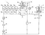
- FIG. 1is a partially-sectioned, schematic view of the pressurization system according to the present invention
- FIG. 2is a partially-sectioned, schematic view of a second embodiment of the pressurization system of the present invention.
- FIG. 3is a partially-sectioned, schematic view of a detail of the pressurization system of the invention, in accordance with a third embodiment.
- the pressurization systemacts on a high hydrostatic-pressure pressurization device 2 comprising a housing 3 which has a removable closure element 4 and inside which a pressurization chamber 5 is defined for housing one or more objects 6 , for example bottles, to be processed at high hydrostatic pressures.
- a piston 7acting inside the pressurization chamber 5 , has a T-shaped cross-section the larger-diameter end of which defines, together with the walls of the housing 3 , a chamber 8 filled with a substantially incompressible fluid which, in the embodiment described, is hydraulic oil.
- a duct(not shown in the drawing), extending throughout a wall of the housing 3 which defines the chamber 8 , is connected to the pressurization system of the present invention by means of a tube 9 which admits the hydraulic oil to the chamber 8 at high pressure.
- An example of a pressurization device to which the pressurization system of the present invention may advantageously be appliedis that described in the European patent application No. 00830705.0 which was filed on 26th Oct. 2000 in the name of the Applicant of the present patent application and the description of which is incorporated herein by reference.
- the tube 9is connected, by means of respective tube connectors 9 a , 9 b , 9 c , 9 d , 9 e , to a plurality of primary pressure accumulators 10 a , 10 b , 10 c , 10 d , 10 e , which are filled with hydraulic oil for part of their volumes, the remaining part of their volumes being occupied by an inert gas, for example nitrogen, under pressure.
- the pressure to which the gas is subjected in the reservoirsis preferably approximately 300 bar.
- direct-pressurization valve means 11Interposed in the path of the tube 9 from the primary pressure accumulators 10 a , 10 b , 10 c , 10 d , 10 e to the pressurization device 2 are direct-pressurization valve means 11 , for example, a solenoid valve the opening of which enables the pressure stored by the precompressed gas in the accumulators to be discharged onto the piston 7 of the pressurization device 2 , as will be described further below.
- a pump 12drawing hydraulic oil from a reservoir 13 and admitting it to the tubing circuit 9 , 9 a , 9 b , 9 c , 9 d , 9 e through a charging tube 14 , keeps the primary pressure accumulators 10 a , 10 b , 10 c , 10 d , 10 e under pressure.
- charging-valve means 15for example, a solenoid valve with open/shut control and, downstream thereof, a non-return valve 16 , the function of which is to prevent the excess pressure being vented from the primary accumulators 10 a , 10 b , 10 c , 10 d , 10 e towards the pump 12 .
- the tube 9branches into a secondary tube 17 .
- This secondary tube 17is connected, by indirect-pressurization valve means 18 , for example, a solenoid valve, to pressure-multiplier means 19 such as a hydraulic pressure-multiplier.
- the valve means 18comprises two outlets, that is, a pressurization outlet 29 and a discharge outlet 30 , and an inlet 32 , which are controllable separately.
- the means 18may be a three-way solenoid valve, operable in accordance with the following operative conditions: a) completely closed, b) pressurization outlet 29 and discharge outlet 30 in flow communication, inlet shut, c) inlet and pressurization outlet 29 in flow communication, discharge outlet 30 shut.
- the discharge outlet 30discharges hydraulic oil towards the reservoir 13 by means of a duct provided with valve means 31 with open/shut control.
- the pressure-multiplier 19comprises a housing 20 made of a material suitable for withstanding high pressures.
- a material suitable for withstanding high pressuresis a multi-layer jacket such as that described in the above-mentioned European patent application No. 00830705.0 filed on 26th Oct. 2000, the description of which, in particular with regard to this multi-layer jacket and the structure of the pressurization piston, is incorporated herein by reference.
- a piston 21 housed for sliding in the housing 20has a T-shaped cross-section the larger-diameter end of which defines, together with the walls of the housing 20 , a first chamber 22 filled with hydraulic oil, into which the secondary tube 17 opens.
- a second chamber 23which in turn is filled with oil, is defined by the smaller-diameter end of the piston 21 and by the walls of the housing 20 .
- the space 28 between the upper shoulder of the piston 21 and the body of the housing 20which, at this point, has a thickness such as to be engaged for sliding by the smaller-diameter section of the piston,—defines the stroke of the piston 21 .
- the chamber 23is in fluid communication with a connecting duct 24 which is reconnected to the tube 9 downstream of the direct-preassurization valve means 11 .
- a non-return valve 25is interposed in the connecting duct 24 , upstream of the point of connection with the tube 9 .
- the tube 9is connected, in the portion disposed between the direct-pressurization valve means 11 and the pressurization device 2 , to a duct 26 for discharging the hydraulic oil from the pressurization device 2 to the oil reservoir 13 .
- Discharge-valve means 27for example, a solenoid valve, are interposed in the path of the discharge duct 26 .
- the hydraulic apparatus of the pressurization systemthat is, the tubes 9 , 14 , 24 , 26 , the chambers 8 , 22 , 23 of the pressure-multipliers and parts of the primary pressure accumulators 10 a , 10 b , 10 c , 10 d , 10 e , is filled with hydraulic oil.
- the pump 12which draws hydraulic oil from the reservoir 13 and admits it to the primary accumulators 10 a , 10 b , 10 c , 10 d , 10 e , under pressure, through the charging tube 14 , keeps the pressure of the inert gas in these accumulators above a predetermined operating level which, in the embodiment described, is about 300 bar.
- the non-return valve 16prevents discharge of the pressure from the accumulators towards the pump 12 .
- the direct-pressurization valve means 11which are closed in the rest condition, open, allowing some of the pressure accumulated in the primary accumulators 10 a , 10 b , 10 c , 10 d , 10 e to be discharged instantaneously along the tube 9 and into the chamber 8 of the pressurization device 2 .
- the indirect-pressurization valve means 18 and the discharge-valve means 27are closed. The first pressurization stage continues until the pressure in the chamber 8 is in equilibrium with that in the accumulators.
- the pressure in the chamber 8will be substantially equal to the initial pressure of the gas in the accumulators, that is, in the embodiment described, about 300 bar. This effect is achieved, as stated, by the provision of a volume of precompressed gas definitely greater than the volume of hydraulic oil entering the chamber 8 of the pressurization device 2 .
- the second pressurization stagebegins; this provides for the closure of the direct-pressurization valve means 11 and the activation of the indirect-pressurization valve means 18 .
- the pressurization outlet 29will be opened and the discharge outlet 30 will be kept closed.
- the potential energy stored in the form of pressurized gas in the primary pressure accumulators 10 a , 10 b , 10 c , 10 d , 10 eis discharged, in this case, along the secondary tube 17 and through the pressure-multiplier 19 to the chamber 8 of the pressurization device 2 .
- the operation of the pressure-multiplier 19is based on the presence of a piston 21 with a T-shaped cross-section.
- the pressure reached at the outlet of the pressure-multiplier 19will be proportional to the ratio between the lower surface (in contact with the chamber 22 ) and the upper surface of the piston. For example, if the ratio between these two areas is 2 , the oil pressure will be doubled, at least as a first approximation. In the embodiment described, the pressure output by the pressure-multiplier 19 will therefore be about 600 bar.
- the piston 7 of the pressurization device 2When the equilibrium condition is reached, the piston 7 of the pressurization device 2 will also be subject to this pressure, which will therefore be transferred, after suitable amplification by means of the piston 7 as described above for the piston 21 , into the pressurization chamber 5 and onto the object 6 to be processed which, in the example described, is a bottle to be sterilized.
- the piston 7 of the pressurization device 2With suitable dimensions of the smaller and larger surfaces 7 of the piston, it will be possible to achieve a pressure of a few thousand bar in the pressurization chamber 5 .
- the decompression stagewhich in turn is composed of two distinct stages, will start.
- the discharge-valve means 27 and the indirect-pressurization valve means 18will remain closed (operative condition a), see above), whilst the direct-pressurization valve means 11 will be opened.
- the hydraulic oilwill thus flow in the opposite direction to that in which it flowed in the pressurization stage, so as to compress the gas in the accumulators until equilibrium is reached, that is, until the chamber 8 is decompressed to the equilibrium pressure of 300 bar.
- the non-return valve 25will enable the pressure-multiplier 19 which, in this case, would operate in reverse, to be bypassed. The device thus clearly permits at least partial recovery of the potential energy expended in the compression of the fluid to 600 bar in the chamber 8 .
- an operating and control unitnormally of the electronic type, which provides for the opening and closure of the valve means, the operation of the pump 12 , and for any other additional operations such as those required by the particular application to which the pressurization system of the present invention is dedicated.
- these operationsmay relate to the closure and opening of the closure element 4 of the pressurization device 2 , to the insertion or removal of the bottle 6 , and to monitoring of temperature, pressure or any other operative conditions required. Examples of these additional operations are those described in the above-mentioned European patent application No. 00830705.0 filed on Oct 26, 2000.
- FIG. 2differs from the first embodiment described above in the provision of a third hydraulic circuit entrusted with performing some auxiliary functions of the system, in particular, the resetting of the piston 21 of the pressure-multiplier 19 , that is, its return to its initial position upon completion of the pressurization cycle.
- reference numerals the same as those indicated in FIG. 1correspond to the same parts of the system. The pressurization system will therefore be described only with reference to the additional characteristics, the foregoing description remaining the same for the rest of the system.
- the charging-valve means 115 disposed downstream of the pump 12have three separately controllable outlets.
- the first outletis connected to the charging tube 14 , as described above.
- a second outletis in fluid communication with a secondary charging tube 128 which in turn is connected to a secondary pressure accumulator 129 .
- a non-return valve 130is disposed upstream of this accumulator.
- a third outletis in fluid communication with a recirculation duct 131 which returns the hydraulic oil to the pump when the other two outlets of the valve means 115 are closed. This arrangement enables the pump 12 always to be kept in operation throughout the operation of the system, avoiding constant starting and stopping which are detrimental to the operation of the pump.
- the secondary accumulator 129is just the same as the primary accumulators 10 a , 10 b , 10 c , 10 d , 10 e described above, with the sole possible difference that the pressure of the gas compressed inside it may be kept lower than that of the primary accumulators because of the lower energy normally required by the auxiliary operations to which the secondary accumulator is dedicated. In the example described, this pressure is about 150 bar.
- the secondary charging tube 128is in fluid communication, in the portion between the non-return valve 130 and the secondary accumulator 129 , with an auxiliary tube 132 which opens inside the pressure-multiplier 19 in the space 28 which defines the stroke of the piston 21 .
- auxiliary tube 132Interposed in this auxiliary tube 132 are valve means 133 with open/shut control and, downstream thereof, a non-return valve 134 .
- a discharge tube 135 provided with a non-return valve 136puts the space 28 into flow communication with the tube connected to the discharge outlet 30 of the valve means 18 , upstream of the valve means 31 .
- the operation of the pressurization system according to the embodiment of FIG. 2is exactly the same as that described above for the first embodiment.
- the charging-valve means 115will keep the outlets towards the tubes 14 and 128 open whilst the outlet towards the recirculation duct 131 will remain closed.
- the pressurization-valve means 133will be closed.
- the valve means 133 of the auxiliary tube 132will remain closed whilst the valve means 31 will be in the open condition.
- the secondary pressurization-valve means 18will be either in operative condition a) (first pressurization stage) or in operative condition c) (second pressurization stage).
- valve means 31Upon completion of the pressurization cycle described above, the valve means 31 will be closed and the valve means 133 will be opened and will provide for the admission of oil under pressure to the space 28 , causing the piston to return to its starting position. Upon completion of this operation, the valve means 31 will be opened and the valve means 18 will be put in operative condition b), enabling the pressure accumulated in the chamber 22 and in the space 28 of the pressure-multiplier 19 to be discharged.
- the system of the present inventionmay advantageously comprise pressure sensors for detecting the pressure in the primary pressure accumulators 10 a , 10 b , 10 c , 10 d , 10 e and in the secondary accumulator 129 . These pressure sensors send a signal to the operating and control unit that controls the outlets of the valve means 115 which are connected, respectively, to the charging tube 14 , to the secondary charging tube 128 , or to the recirculation duct 131 .
- the pressure in the primary accumulators 10 a , 10 b , 10 c , 10 d , 10 ereaches the pressure set (in the embodiment described, about 300 bar)
- the outlet of the valve relating to the tube 14is thus blocked.
- the desired pressure of about 150 baris reached in the secondary accumulator 129
- the outlet for the tube 128is blocked.
- the operating and control unitprovides for the outlet to the recirculation duct 131 to be opened.
- the system of the inventionthus enables the pressure in the pressure accumulators to be kept almost constant, without the need to interrupt the operation of the pump 12 , even during the stage of the pressurization of the pressurization device 2 .
- the secondary hydraulic circuit connected to the secondary pressure accumulator 129also operates the mechanism for opening and closing the pressurization device 2 .
- the closure element 4is a cylinder with a transverse through-hole for the insertion of a pin 136 .
- the pin 136also extends through the wall of the housing 3 of the device and has the function of a lock for the closure element 4 so as to cope with the axial thrusts of the system.
- the pin 136constitutes the shaft of a piston 137 housed for sliding in a housing 138 of the pin piston.
- the piston 137defines, in the housing 138 , a return chamber 140 (which the surface of the piston carrying the pin 136 faces) and a thrust chamber 139 (which the opposite surface of the piston faces).
- the closure element 4is fixed at the top to a shaft 141 which in turn terminates, at its opposite end, in a piston 142 housed for sliding in a housing 143 of the closure piston.
- the piston 142defines in the housing 143 , a return chamber 144 (which the surface of the piston carrying the shaft 141 faces) and a thrust chamber 145 (which the opposite surface of the piston faces).
- valve means 133 connected to the secondary pressure accumulator 129will have three outlets.
- the first outletis connected to the secondary tube 132 , as described above.
- the second outletis in fluid communication, by means of a duct 146 , with closure-control valve means 147 .
- the third outletis in fluid communication, by means of a duct 148 , with pin-control valve means 149 .
- the three outletsare operable independently.
- the closure-control valve means 147in turn have two outlets.
- the first outletis connected to a thrust tube 150 which brings hydraulic oil to the thrust chamber 145 of the closure-piston housing 143 .
- the second outletis connected to a return tube 151 which brings hydraulic oil to the return chamber 144 of the closure-piston housing 143 .
- the pin-control valve means 149has two outlets.
- the first outletis connected to a thrust tube 152 which brings hydraulic oil to the thrust chamber 139 of the pin-piston housing 138 .
- the second outletis connected to a return tube 153 which brings hydraulic oil to the return chamber 140 of the pin-piston housing 138 .
- Both the thrust tubes 150 , 152 and the return tubes 151 , 153are in flow communication with respective ducts which recirculate the oil to the reservoir 13 .
- Each of these ductshas valve means (not shown in the drawing) which open and close alternately.
- the sequence of operationswill be as follows.
- the outlet of the valve means 133 to the duct 146is opened and, at the same time, the closure-control valve means 147 open the outlet to the thrust tube 150 which admits oil to the thrust chamber 145 .
- the oil present in the return chamber 144will therefore be pumped along the return tube 151 by the piston and, finding the valve means 147 closed, will be directed into the duct which recirculates the oil to the reservoir 13 , the valve of which will therefore be in the open condition.
- the closure element 4will fall onto the opening of the housing 3 of the pressurization device 2 to block this opening.
- the valve means 147will keep both of the outlets in the closed condition, whilst the valve means 149 will open the outlet for the thrust tube 152 .
- the pin 136will also be inserted through the holes in the casing 3 of the device and of the closure element 4 by a mechanism similar to that described above for the closure element 4 .
- the oil discharged from the return chamber 140 of the pin-piston housing 138will be directed into the respective recirculation duct towards the reservoir 13 , after the valve means connected thereto have been opened.
- the same sequence of stepswill be repeated, but in reverse, for the release and removal of the closure element 4 upon completion of the pressurization cycle.
- the systemprovides for the storage of potential energy in the form of pressurized gas in the pressure accumulators and its instantaneous release at the moment of use by kinetics approaching those of a deflagration.
- This mechanismreduces to the minimum the times required for the pressurization stage so that cycles comprising pressurizations and partial decompressions can be performed in accordance with predetermined profiles which are particularly advantageous in some applications (for example, sterilization of foods or beverages in containers). For example, it will be possible to bring the pressure in the chamber 8 of the pressurization device 2 from atmospheric pressure to 600 bar in about 5 seconds, and partial decompression to 500 bar and repressurization to 600 bar may require only about 2 seconds.
- a pressure-multiplier 19which can be operated at the pressurization stage and bypassed at the decompression stage permits partial recovery of the potential energy, optimizing the energy cycle of the system.
- the provision of the secondary pressure accumulator 129has the advantage that some auxiliary functions such as the resetting of the pressure-multiplier piston and the opening/closure of the closure element of the pressurization device are also brought about by the same hydraulic system and within the same short times. For example, this latter operation can also be carried out in a time generally of between 4 and 4.5 seconds.
- the pressurization system according to the inventionis composed substantially of a hydraulic circuit, mechanical componentry (mechanical actuators, cams, etc.) can be minimized, with a consequent reduction in the maintenance costs of the system.
- the number of primary pressure accumulators 10 a , 10 b , 10 c , 10 d , 10 emay be increased or reduced according to the requirements and the size of the plant.
Landscapes
- Engineering & Computer Science (AREA)
- Physics & Mathematics (AREA)
- General Engineering & Computer Science (AREA)
- Mechanical Engineering (AREA)
- Fluid Mechanics (AREA)
- Chemical & Material Sciences (AREA)
- Life Sciences & Earth Sciences (AREA)
- Polymers & Plastics (AREA)
- Food Science & Technology (AREA)
- Zoology (AREA)
- Wood Science & Technology (AREA)
- Analytical Chemistry (AREA)
- Fluid-Pressure Circuits (AREA)
- Supply Devices, Intensifiers, Converters, And Telemotors (AREA)
- Press Drives And Press Lines (AREA)
- Food Preservation Except Freezing, Refrigeration, And Drying (AREA)
Abstract
Description
Claims (22)
Applications Claiming Priority (1)
| Application Number | Priority Date | Filing Date | Title |
|---|---|---|---|
| PCT/IT2001/000175WO2002086326A1 (en) | 2001-04-06 | 2001-04-06 | Hydraulic pressurization system |
Publications (2)
| Publication Number | Publication Date |
|---|---|
| US20040168436A1 US20040168436A1 (en) | 2004-09-02 |
| US7107766B2true US7107766B2 (en) | 2006-09-19 |
Family
ID=11133648
Family Applications (1)
| Application Number | Title | Priority Date | Filing Date |
|---|---|---|---|
| US10/474,166Expired - Fee RelatedUS7107766B2 (en) | 2001-04-06 | 2001-04-06 | Hydraulic pressurization system |
Country Status (7)
| Country | Link |
|---|---|
| US (1) | US7107766B2 (en) |
| EP (1) | EP1373737B1 (en) |
| JP (1) | JP2004534925A (en) |
| AT (1) | ATE276442T1 (en) |
| CA (1) | CA2442393A1 (en) |
| DE (1) | DE60105656D1 (en) |
| WO (1) | WO2002086326A1 (en) |
Cited By (31)
| Publication number | Priority date | Publication date | Assignee | Title |
|---|---|---|---|---|
| US7802426B2 (en) | 2008-06-09 | 2010-09-28 | Sustainx, Inc. | System and method for rapid isothermal gas expansion and compression for energy storage |
| US7832207B2 (en) | 2008-04-09 | 2010-11-16 | Sustainx, Inc. | Systems and methods for energy storage and recovery using compressed gas |
| US7958731B2 (en) | 2009-01-20 | 2011-06-14 | Sustainx, Inc. | Systems and methods for combined thermal and compressed gas energy conversion systems |
| US7963110B2 (en) | 2009-03-12 | 2011-06-21 | Sustainx, Inc. | Systems and methods for improving drivetrain efficiency for compressed gas energy storage |
| US8037678B2 (en) | 2009-09-11 | 2011-10-18 | Sustainx, Inc. | Energy storage and generation systems and methods using coupled cylinder assemblies |
| US8046990B2 (en) | 2009-06-04 | 2011-11-01 | Sustainx, Inc. | Systems and methods for improving drivetrain efficiency for compressed gas energy storage and recovery systems |
| US8104274B2 (en) | 2009-06-04 | 2012-01-31 | Sustainx, Inc. | Increased power in compressed-gas energy storage and recovery |
| US8117842B2 (en) | 2009-11-03 | 2012-02-21 | Sustainx, Inc. | Systems and methods for compressed-gas energy storage using coupled cylinder assemblies |
| US8171728B2 (en) | 2010-04-08 | 2012-05-08 | Sustainx, Inc. | High-efficiency liquid heat exchange in compressed-gas energy storage systems |
| US8191362B2 (en) | 2010-04-08 | 2012-06-05 | Sustainx, Inc. | Systems and methods for reducing dead volume in compressed-gas energy storage systems |
| US8225606B2 (en) | 2008-04-09 | 2012-07-24 | Sustainx, Inc. | Systems and methods for energy storage and recovery using rapid isothermal gas expansion and compression |
| US8234863B2 (en) | 2010-05-14 | 2012-08-07 | Sustainx, Inc. | Forming liquid sprays in compressed-gas energy storage systems for effective heat exchange |
| US8240140B2 (en) | 2008-04-09 | 2012-08-14 | Sustainx, Inc. | High-efficiency energy-conversion based on fluid expansion and compression |
| US8250863B2 (en) | 2008-04-09 | 2012-08-28 | Sustainx, Inc. | Heat exchange with compressed gas in energy-storage systems |
| US8359856B2 (en) | 2008-04-09 | 2013-01-29 | Sustainx Inc. | Systems and methods for efficient pumping of high-pressure fluids for energy storage and recovery |
| US8448433B2 (en) | 2008-04-09 | 2013-05-28 | Sustainx, Inc. | Systems and methods for energy storage and recovery using gas expansion and compression |
| US8474255B2 (en) | 2008-04-09 | 2013-07-02 | Sustainx, Inc. | Forming liquid sprays in compressed-gas energy storage systems for effective heat exchange |
| US8479505B2 (en) | 2008-04-09 | 2013-07-09 | Sustainx, Inc. | Systems and methods for reducing dead volume in compressed-gas energy storage systems |
| US20130175045A1 (en)* | 2012-01-06 | 2013-07-11 | Schlumberger Technology Corporation | In-riser hydraulic power recharging |
| US8495872B2 (en) | 2010-08-20 | 2013-07-30 | Sustainx, Inc. | Energy storage and recovery utilizing low-pressure thermal conditioning for heat exchange with high-pressure gas |
| US8539763B2 (en) | 2011-05-17 | 2013-09-24 | Sustainx, Inc. | Systems and methods for efficient two-phase heat transfer in compressed-air energy storage systems |
| US8578708B2 (en) | 2010-11-30 | 2013-11-12 | Sustainx, Inc. | Fluid-flow control in energy storage and recovery systems |
| US8667792B2 (en) | 2011-10-14 | 2014-03-11 | Sustainx, Inc. | Dead-volume management in compressed-gas energy storage and recovery systems |
| US8677744B2 (en) | 2008-04-09 | 2014-03-25 | SustaioX, Inc. | Fluid circulation in energy storage and recovery systems |
| US8839617B2 (en) | 2011-09-30 | 2014-09-23 | Caterpillar Inc. | System and method for controlling charging of an accumulator in an electro-hydraulic system |
| US20140290972A1 (en)* | 2011-10-10 | 2014-10-02 | Angus Peter Robson | Accumulator |
| US20170145773A1 (en)* | 2015-11-19 | 2017-05-25 | Cameron International Corporation | Closed-Loop Solenoid System |
| US9879700B1 (en) | 2014-07-22 | 2018-01-30 | Boston Dynamics, Inc. | Robotic hydraulic system |
| US10132135B2 (en)* | 2015-08-05 | 2018-11-20 | Cameron International Corporation | Subsea drilling system with intensifier |
| US10570930B2 (en) | 2011-10-10 | 2020-02-25 | Angus Peter Robson | Accumulator |
| US11105172B2 (en)* | 2017-06-29 | 2021-08-31 | Equinor Energy As | Tubing hanger installation tool |
Families Citing this family (11)
| Publication number | Priority date | Publication date | Assignee | Title |
|---|---|---|---|---|
| US20120021107A1 (en)* | 2010-07-23 | 2012-01-26 | Robert Andrew Knowlton | Method and apparatus for processing produce |
| US11242236B2 (en) | 2015-03-19 | 2022-02-08 | Phillip LaBarbera | Perfect pour drink mixer |
| CN105054214A (en)* | 2015-07-30 | 2015-11-18 | 华南农业大学 | Water-hydraulic ultrahigh pressure system for liquid food and production device thereof |
| CN106151126B (en)* | 2016-08-26 | 2018-04-27 | 北京精密机电控制设备研究所 | A kind of servo control mechanism of parallel operation is from boost-up circuit |
| KR20210016457A (en) | 2018-06-01 | 2021-02-15 | 인 스피릿 그룹, 인크. | Multi-compartment beverage container system and method |
| DK3722619T3 (en)* | 2019-04-11 | 2022-01-24 | Piston Power S R O | HYDRAULIC PRESSURE AMPLIFIER ARRANGEMENT |
| DE102019210944B4 (en)* | 2019-07-24 | 2022-07-07 | Thyssenkrupp Ag | Device and method for building up pressure in high-pressure treatment processes using a plurality of pumps and use |
| JP7263218B2 (en)* | 2019-11-27 | 2023-04-24 | 株式会社東芝 | hydraulic circuit |
| CN110864021B (en)* | 2019-12-02 | 2021-07-27 | 郑州磨料磨具磨削研究所有限公司 | Synchronous control system for hydraulic oil cylinder of cubic press |
| CN110873085B (en)* | 2019-12-02 | 2021-07-27 | 郑州磨料磨具磨削研究所有限公司 | Synchronous control method for hydraulic oil cylinder of cubic press |
| CN115163009B (en)* | 2022-07-06 | 2023-08-18 | 商丘睿控仪器仪表有限公司 | Underground Large Volume Liquid Autonomous Pumping System |
Citations (13)
| Publication number | Priority date | Publication date | Assignee | Title |
|---|---|---|---|---|
| US1888990A (en) | 1929-08-16 | 1932-11-29 | Economy Fuse And Mfg Co | Automatically controlled hydraulic press intensifier |
| FR930207A (en) | 1945-07-17 | 1948-01-20 | Improved method and apparatus for applying hydraulic pressure | |
| US2706891A (en)* | 1952-05-31 | 1955-04-26 | Greer Hydraulics Inc | Pressure intensifier system |
| US3945206A (en)* | 1973-11-22 | 1976-03-23 | Ruthner Industrieanlagen-Aktiengesellschaft | Control system for hydraulic presses comprising a plurality of press rams |
| US3945207A (en) | 1974-07-05 | 1976-03-23 | James Ervin Hyatt | Hydraulic propulsion system |
| US4142368A (en)* | 1976-10-28 | 1979-03-06 | Welko Industriale S.P.A. | Hydraulic system for supplying hydraulic fluid to a hydraulically operated device alternately at pressures of different value |
| WO1987001161A1 (en) | 1981-05-26 | 1987-02-26 | Clark Garry E | Fluid driven power plant |
| US4693080A (en) | 1984-09-21 | 1987-09-15 | Van Rietschoten & Houwens Technische Handelmaatschappij B.V. | Hydraulic circuit with accumulator |
| US4924671A (en)* | 1986-11-25 | 1990-05-15 | Mannesmann Rexroth Gmbh | Controlled series high-pressure intensifiers for hydraulic press cylinded circuit |
| US4955195A (en)* | 1988-12-20 | 1990-09-11 | Stewart & Stevenson Services, Inc. | Fluid control circuit and method of operating pressure responsive equipment |
| US5971027A (en) | 1996-07-01 | 1999-10-26 | Wisconsin Alumni Research Foundation | Accumulator for energy storage and delivery at multiple pressures |
| WO2000037800A1 (en) | 1998-12-22 | 2000-06-29 | Tcg Unitech Aktiengesellschaft | Device for converting energy being stored in compressed air into mechanical work |
| EP1048608A1 (en) | 1999-04-29 | 2000-11-02 | Sasib Beverage Machinery M.S. S.p.A. | Continuous method and apparatus for the sterilization of bottled drinks |
- 2001
- 2001-04-06EPEP01925868Apatent/EP1373737B1/ennot_activeExpired - Lifetime
- 2001-04-06ATAT01925868Tpatent/ATE276442T1/ennot_activeIP Right Cessation
- 2001-04-06USUS10/474,166patent/US7107766B2/ennot_activeExpired - Fee Related
- 2001-04-06CACA002442393Apatent/CA2442393A1/ennot_activeAbandoned
- 2001-04-06WOPCT/IT2001/000175patent/WO2002086326A1/enactiveIP Right Grant
- 2001-04-06DEDE60105656Tpatent/DE60105656D1/ennot_activeExpired - Lifetime
- 2001-04-06JPJP2002583823Apatent/JP2004534925A/enactivePending
Patent Citations (13)
| Publication number | Priority date | Publication date | Assignee | Title |
|---|---|---|---|---|
| US1888990A (en) | 1929-08-16 | 1932-11-29 | Economy Fuse And Mfg Co | Automatically controlled hydraulic press intensifier |
| FR930207A (en) | 1945-07-17 | 1948-01-20 | Improved method and apparatus for applying hydraulic pressure | |
| US2706891A (en)* | 1952-05-31 | 1955-04-26 | Greer Hydraulics Inc | Pressure intensifier system |
| US3945206A (en)* | 1973-11-22 | 1976-03-23 | Ruthner Industrieanlagen-Aktiengesellschaft | Control system for hydraulic presses comprising a plurality of press rams |
| US3945207A (en) | 1974-07-05 | 1976-03-23 | James Ervin Hyatt | Hydraulic propulsion system |
| US4142368A (en)* | 1976-10-28 | 1979-03-06 | Welko Industriale S.P.A. | Hydraulic system for supplying hydraulic fluid to a hydraulically operated device alternately at pressures of different value |
| WO1987001161A1 (en) | 1981-05-26 | 1987-02-26 | Clark Garry E | Fluid driven power plant |
| US4693080A (en) | 1984-09-21 | 1987-09-15 | Van Rietschoten & Houwens Technische Handelmaatschappij B.V. | Hydraulic circuit with accumulator |
| US4924671A (en)* | 1986-11-25 | 1990-05-15 | Mannesmann Rexroth Gmbh | Controlled series high-pressure intensifiers for hydraulic press cylinded circuit |
| US4955195A (en)* | 1988-12-20 | 1990-09-11 | Stewart & Stevenson Services, Inc. | Fluid control circuit and method of operating pressure responsive equipment |
| US5971027A (en) | 1996-07-01 | 1999-10-26 | Wisconsin Alumni Research Foundation | Accumulator for energy storage and delivery at multiple pressures |
| WO2000037800A1 (en) | 1998-12-22 | 2000-06-29 | Tcg Unitech Aktiengesellschaft | Device for converting energy being stored in compressed air into mechanical work |
| EP1048608A1 (en) | 1999-04-29 | 2000-11-02 | Sasib Beverage Machinery M.S. S.p.A. | Continuous method and apparatus for the sterilization of bottled drinks |
Non-Patent Citations (1)
| Title |
|---|
| International Search Report dated Feb. 13, 2002, for Application No. PCT/IT01/00175. |
Cited By (52)
| Publication number | Priority date | Publication date | Assignee | Title |
|---|---|---|---|---|
| US8479505B2 (en) | 2008-04-09 | 2013-07-09 | Sustainx, Inc. | Systems and methods for reducing dead volume in compressed-gas energy storage systems |
| US8733094B2 (en) | 2008-04-09 | 2014-05-27 | Sustainx, Inc. | Systems and methods for energy storage and recovery using rapid isothermal gas expansion and compression |
| US7900444B1 (en) | 2008-04-09 | 2011-03-08 | Sustainx, Inc. | Systems and methods for energy storage and recovery using compressed gas |
| US8474255B2 (en) | 2008-04-09 | 2013-07-02 | Sustainx, Inc. | Forming liquid sprays in compressed-gas energy storage systems for effective heat exchange |
| US8763390B2 (en) | 2008-04-09 | 2014-07-01 | Sustainx, Inc. | Heat exchange with compressed gas in energy-storage systems |
| US8733095B2 (en) | 2008-04-09 | 2014-05-27 | Sustainx, Inc. | Systems and methods for efficient pumping of high-pressure fluids for energy |
| US8713929B2 (en) | 2008-04-09 | 2014-05-06 | Sustainx, Inc. | Systems and methods for energy storage and recovery using compressed gas |
| US8677744B2 (en) | 2008-04-09 | 2014-03-25 | SustaioX, Inc. | Fluid circulation in energy storage and recovery systems |
| US8627658B2 (en) | 2008-04-09 | 2014-01-14 | Sustainx, Inc. | Systems and methods for energy storage and recovery using rapid isothermal gas expansion and compression |
| US7832207B2 (en) | 2008-04-09 | 2010-11-16 | Sustainx, Inc. | Systems and methods for energy storage and recovery using compressed gas |
| US8448433B2 (en) | 2008-04-09 | 2013-05-28 | Sustainx, Inc. | Systems and methods for energy storage and recovery using gas expansion and compression |
| US8359856B2 (en) | 2008-04-09 | 2013-01-29 | Sustainx Inc. | Systems and methods for efficient pumping of high-pressure fluids for energy storage and recovery |
| US8250863B2 (en) | 2008-04-09 | 2012-08-28 | Sustainx, Inc. | Heat exchange with compressed gas in energy-storage systems |
| US8209974B2 (en) | 2008-04-09 | 2012-07-03 | Sustainx, Inc. | Systems and methods for energy storage and recovery using compressed gas |
| US8225606B2 (en) | 2008-04-09 | 2012-07-24 | Sustainx, Inc. | Systems and methods for energy storage and recovery using rapid isothermal gas expansion and compression |
| US8240140B2 (en) | 2008-04-09 | 2012-08-14 | Sustainx, Inc. | High-efficiency energy-conversion based on fluid expansion and compression |
| US8240146B1 (en) | 2008-06-09 | 2012-08-14 | Sustainx, Inc. | System and method for rapid isothermal gas expansion and compression for energy storage |
| US7802426B2 (en) | 2008-06-09 | 2010-09-28 | Sustainx, Inc. | System and method for rapid isothermal gas expansion and compression for energy storage |
| US8234862B2 (en) | 2009-01-20 | 2012-08-07 | Sustainx, Inc. | Systems and methods for combined thermal and compressed gas energy conversion systems |
| US8122718B2 (en) | 2009-01-20 | 2012-02-28 | Sustainx, Inc. | Systems and methods for combined thermal and compressed gas energy conversion systems |
| US7958731B2 (en) | 2009-01-20 | 2011-06-14 | Sustainx, Inc. | Systems and methods for combined thermal and compressed gas energy conversion systems |
| US7963110B2 (en) | 2009-03-12 | 2011-06-21 | Sustainx, Inc. | Systems and methods for improving drivetrain efficiency for compressed gas energy storage |
| US8234868B2 (en) | 2009-03-12 | 2012-08-07 | Sustainx, Inc. | Systems and methods for improving drivetrain efficiency for compressed gas energy storage |
| US8046990B2 (en) | 2009-06-04 | 2011-11-01 | Sustainx, Inc. | Systems and methods for improving drivetrain efficiency for compressed gas energy storage and recovery systems |
| US8104274B2 (en) | 2009-06-04 | 2012-01-31 | Sustainx, Inc. | Increased power in compressed-gas energy storage and recovery |
| US8479502B2 (en) | 2009-06-04 | 2013-07-09 | Sustainx, Inc. | Increased power in compressed-gas energy storage and recovery |
| US8037678B2 (en) | 2009-09-11 | 2011-10-18 | Sustainx, Inc. | Energy storage and generation systems and methods using coupled cylinder assemblies |
| US8468815B2 (en) | 2009-09-11 | 2013-06-25 | Sustainx, Inc. | Energy storage and generation systems and methods using coupled cylinder assemblies |
| US8109085B2 (en) | 2009-09-11 | 2012-02-07 | Sustainx, Inc. | Energy storage and generation systems and methods using coupled cylinder assemblies |
| US8117842B2 (en) | 2009-11-03 | 2012-02-21 | Sustainx, Inc. | Systems and methods for compressed-gas energy storage using coupled cylinder assemblies |
| US8661808B2 (en) | 2010-04-08 | 2014-03-04 | Sustainx, Inc. | High-efficiency heat exchange in compressed-gas energy storage systems |
| US8245508B2 (en) | 2010-04-08 | 2012-08-21 | Sustainx, Inc. | Improving efficiency of liquid heat exchange in compressed-gas energy storage systems |
| US8191362B2 (en) | 2010-04-08 | 2012-06-05 | Sustainx, Inc. | Systems and methods for reducing dead volume in compressed-gas energy storage systems |
| US8171728B2 (en) | 2010-04-08 | 2012-05-08 | Sustainx, Inc. | High-efficiency liquid heat exchange in compressed-gas energy storage systems |
| US8234863B2 (en) | 2010-05-14 | 2012-08-07 | Sustainx, Inc. | Forming liquid sprays in compressed-gas energy storage systems for effective heat exchange |
| US8495872B2 (en) | 2010-08-20 | 2013-07-30 | Sustainx, Inc. | Energy storage and recovery utilizing low-pressure thermal conditioning for heat exchange with high-pressure gas |
| US8578708B2 (en) | 2010-11-30 | 2013-11-12 | Sustainx, Inc. | Fluid-flow control in energy storage and recovery systems |
| US8539763B2 (en) | 2011-05-17 | 2013-09-24 | Sustainx, Inc. | Systems and methods for efficient two-phase heat transfer in compressed-air energy storage systems |
| US8806866B2 (en) | 2011-05-17 | 2014-08-19 | Sustainx, Inc. | Systems and methods for efficient two-phase heat transfer in compressed-air energy storage systems |
| US8839617B2 (en) | 2011-09-30 | 2014-09-23 | Caterpillar Inc. | System and method for controlling charging of an accumulator in an electro-hydraulic system |
| US9790962B2 (en)* | 2011-10-10 | 2017-10-17 | Angus Peter Robson | Accumulator |
| US10570930B2 (en) | 2011-10-10 | 2020-02-25 | Angus Peter Robson | Accumulator |
| US20140290972A1 (en)* | 2011-10-10 | 2014-10-02 | Angus Peter Robson | Accumulator |
| US8667792B2 (en) | 2011-10-14 | 2014-03-11 | Sustainx, Inc. | Dead-volume management in compressed-gas energy storage and recovery systems |
| US20130175045A1 (en)* | 2012-01-06 | 2013-07-11 | Schlumberger Technology Corporation | In-riser hydraulic power recharging |
| US9453385B2 (en)* | 2012-01-06 | 2016-09-27 | Schlumberger Technology Corporation | In-riser hydraulic power recharging |
| US9879700B1 (en) | 2014-07-22 | 2018-01-30 | Boston Dynamics, Inc. | Robotic hydraulic system |
| US10578129B2 (en) | 2014-07-22 | 2020-03-03 | Boston Dynamics, Inc. | Robotic hydraulic system |
| US10132135B2 (en)* | 2015-08-05 | 2018-11-20 | Cameron International Corporation | Subsea drilling system with intensifier |
| US20170145773A1 (en)* | 2015-11-19 | 2017-05-25 | Cameron International Corporation | Closed-Loop Solenoid System |
| US10337277B2 (en)* | 2015-11-19 | 2019-07-02 | Cameron International Corporation | Closed-loop solenoid system |
| US11105172B2 (en)* | 2017-06-29 | 2021-08-31 | Equinor Energy As | Tubing hanger installation tool |
Also Published As
| Publication number | Publication date |
|---|---|
| ATE276442T1 (en) | 2004-10-15 |
| CA2442393A1 (en) | 2002-10-31 |
| EP1373737B1 (en) | 2004-09-15 |
| WO2002086326A1 (en) | 2002-10-31 |
| JP2004534925A (en) | 2004-11-18 |
| US20040168436A1 (en) | 2004-09-02 |
| DE60105656D1 (en) | 2004-10-21 |
| EP1373737A1 (en) | 2004-01-02 |
Similar Documents
| Publication | Publication Date | Title |
|---|---|---|
| US7107766B2 (en) | Hydraulic pressurization system | |
| US4750869A (en) | Method and apparatus for boosting gas from a low-pressure source to a high-pressure receptacle | |
| US20030039554A1 (en) | Method and apparatus for filling a storage vessel with compressed gas | |
| JP3768405B2 (en) | Compression device | |
| US5584664A (en) | Hydraulic gas compressor and method for use | |
| US20010048882A1 (en) | Dual diaphragm pump | |
| US9022750B2 (en) | Alternative methods to generate high pressure by iteration in a high-pressure multichamber | |
| JP2004522580A (en) | Controller for hydraulic press and method of operating hydraulic press | |
| US20240084829A1 (en) | Hydraulic Drive for a Hydraulic Consumer Alternately Pressurized in Opposite Directions during Operation | |
| US5984642A (en) | Pressure intensifier | |
| CN104100581A (en) | Pressurizing cylinder and pressure test pressurizing device | |
| US7565802B2 (en) | High pressure pressing device and a method | |
| CA2419713A1 (en) | A system and method for compressing a fluid | |
| MXPA05001133A (en) | Fluid operated pump. | |
| CN102482930B (en) | Pump for pumping hydraulic well control fluid into a prosuction flowline | |
| US6319214B1 (en) | Valve-less fluid control circuit for rhythmic action devices | |
| USH928H (en) | Liquid compressing gas system | |
| WO1996018036A1 (en) | Pump pressure multiplier | |
| KR20210120905A (en) | Pressure-booster output stabilizer | |
| JPH0270560A (en) | Antiskid controller | |
| SU1562425A1 (en) | Blowout preventer control system | |
| US3407044A (en) | Apparatus for conserving energy in high pressure chemical reactors | |
| CN119123298A (en) | A mixed gas filling system and method | |
| EP0427798B1 (en) | Apparatus for and method of managing liquid under pressure | |
| SU729096A1 (en) | Press hydraulic drive |
Legal Events
| Date | Code | Title | Description |
|---|---|---|---|
| AS | Assignment | Owner name:SIG SIMONAZZI S.P.A., ITALY Free format text:ASSIGNMENT OF ASSIGNORS INTEREST;ASSIGNORS:ZACCHE, VANNI;GORBI, ALESSANDRO;DALCIEO, MASSIMILIANO;REEL/FRAME:015261/0163 Effective date:20040329 | |
| CC | Certificate of correction | ||
| AS | Assignment | Owner name:SIDEL S.P.A., ITALY Free format text:CHANGE OF NAME;ASSIGNOR:SIG SIMONAZZI S.P.A.;REEL/FRAME:022973/0628 Effective date:20090113 | |
| FEPP | Fee payment procedure | Free format text:PAYOR NUMBER ASSIGNED (ORIGINAL EVENT CODE: ASPN); ENTITY STATUS OF PATENT OWNER: LARGE ENTITY | |
| FPAY | Fee payment | Year of fee payment:4 | |
| FPAY | Fee payment | Year of fee payment:8 | |
| FEPP | Fee payment procedure | Free format text:MAINTENANCE FEE REMINDER MAILED (ORIGINAL EVENT CODE: REM.) | |
| LAPS | Lapse for failure to pay maintenance fees | Free format text:PATENT EXPIRED FOR FAILURE TO PAY MAINTENANCE FEES (ORIGINAL EVENT CODE: EXP.); ENTITY STATUS OF PATENT OWNER: LARGE ENTITY | |
| STCH | Information on status: patent discontinuation | Free format text:PATENT EXPIRED DUE TO NONPAYMENT OF MAINTENANCE FEES UNDER 37 CFR 1.362 | |
| FP | Lapsed due to failure to pay maintenance fee | Effective date:20180919 |