US7107534B1 - Storage area network administration - Google Patents
Storage area network administrationDownload PDFInfo
- Publication number
- US7107534B1 US7107534B1US09/275,727US27572799AUS7107534B1US 7107534 B1US7107534 B1US 7107534B1US 27572799 AUS27572799 AUS 27572799AUS 7107534 B1US7107534 B1US 7107534B1
- Authority
- US
- United States
- Prior art keywords
- storage
- raid
- area network
- storage area
- computer systems
- Prior art date
- Legal status (The legal status is an assumption and is not a legal conclusion. Google has not performed a legal analysis and makes no representation as to the accuracy of the status listed.)
- Expired - Lifetime, expires
Links
- 238000012986modificationMethods0.000claimsabstractdescription4
- 230000004048modificationEffects0.000claimsabstractdescription4
- 238000012544monitoring processMethods0.000claimsdescription16
- 230000036541healthEffects0.000claimsdescription7
- 239000003607modifierSubstances0.000claimsdescription5
- 238000004891communicationMethods0.000claimsdescription4
- 238000003491arrayMethods0.000abstractdescription19
- 238000000034methodMethods0.000description12
- 230000009977dual effectEffects0.000description7
- 238000012546transferMethods0.000description6
- 230000007613environmental effectEffects0.000description4
- 239000000835fiberSubstances0.000description4
- 230000008569processEffects0.000description4
- 230000008901benefitEffects0.000description3
- 238000012937correctionMethods0.000description3
- 238000005516engineering processMethods0.000description3
- 230000008859changeEffects0.000description2
- 238000004590computer programMethods0.000description2
- 238000013500data storageMethods0.000description2
- 238000010586diagramMethods0.000description2
- 238000012806monitoring deviceMethods0.000description2
- 238000012552reviewMethods0.000description2
- 238000012790confirmationMethods0.000description1
- 238000013506data mappingMethods0.000description1
- 238000012217deletionMethods0.000description1
- 230000037430deletionEffects0.000description1
- 238000003780insertionMethods0.000description1
- 230000037431insertionEffects0.000description1
- 238000007726management methodMethods0.000description1
- 238000013507mappingMethods0.000description1
- NJPPVKZQTLUDBO-UHFFFAOYSA-NnovaluronChemical groupC1=C(Cl)C(OC(F)(F)C(OC(F)(F)F)F)=CC=C1NC(=O)NC(=O)C1=C(F)C=CC=C1FNJPPVKZQTLUDBO-UHFFFAOYSA-N0.000description1
- 238000011112process operationMethods0.000description1
- 238000012545processingMethods0.000description1
- 230000008929regenerationEffects0.000description1
- 238000011069regeneration methodMethods0.000description1
- 230000008439repair processEffects0.000description1
Images


Classifications
- H—ELECTRICITY
- H04—ELECTRIC COMMUNICATION TECHNIQUE
- H04L—TRANSMISSION OF DIGITAL INFORMATION, e.g. TELEGRAPHIC COMMUNICATION
- H04L67/00—Network arrangements or protocols for supporting network services or applications
- H04L67/01—Protocols
- H04L67/10—Protocols in which an application is distributed across nodes in the network
- H04L67/1097—Protocols in which an application is distributed across nodes in the network for distributed storage of data in networks, e.g. transport arrangements for network file system [NFS], storage area networks [SAN] or network attached storage [NAS]
- H—ELECTRICITY
- H04—ELECTRIC COMMUNICATION TECHNIQUE
- H04L—TRANSMISSION OF DIGITAL INFORMATION, e.g. TELEGRAPHIC COMMUNICATION
- H04L41/00—Arrangements for maintenance, administration or management of data switching networks, e.g. of packet switching networks
- H04L41/22—Arrangements for maintenance, administration or management of data switching networks, e.g. of packet switching networks comprising specially adapted graphical user interfaces [GUI]
- H—ELECTRICITY
- H04—ELECTRIC COMMUNICATION TECHNIQUE
- H04L—TRANSMISSION OF DIGITAL INFORMATION, e.g. TELEGRAPHIC COMMUNICATION
- H04L67/00—Network arrangements or protocols for supporting network services or applications
- H04L67/50—Network services
- H04L67/75—Indicating network or usage conditions on the user display
- H—ELECTRICITY
- H04—ELECTRIC COMMUNICATION TECHNIQUE
- H04L—TRANSMISSION OF DIGITAL INFORMATION, e.g. TELEGRAPHIC COMMUNICATION
- H04L43/00—Arrangements for monitoring or testing data switching networks
- H—ELECTRICITY
- H04—ELECTRIC COMMUNICATION TECHNIQUE
- H04L—TRANSMISSION OF DIGITAL INFORMATION, e.g. TELEGRAPHIC COMMUNICATION
- H04L43/00—Arrangements for monitoring or testing data switching networks
- H04L43/08—Monitoring or testing based on specific metrics, e.g. QoS, energy consumption or environmental parameters
- Y—GENERAL TAGGING OF NEW TECHNOLOGICAL DEVELOPMENTS; GENERAL TAGGING OF CROSS-SECTIONAL TECHNOLOGIES SPANNING OVER SEVERAL SECTIONS OF THE IPC; TECHNICAL SUBJECTS COVERED BY FORMER USPC CROSS-REFERENCE ART COLLECTIONS [XRACs] AND DIGESTS
- Y10—TECHNICAL SUBJECTS COVERED BY FORMER USPC
- Y10S—TECHNICAL SUBJECTS COVERED BY FORMER USPC CROSS-REFERENCE ART COLLECTIONS [XRACs] AND DIGESTS
- Y10S715/00—Data processing: presentation processing of document, operator interface processing, and screen saver display processing
- Y10S715/961—Operator interface with visual structure or function dictated by intended use
- Y10S715/965—Operator interface with visual structure or function dictated by intended use for process control and configuration
- Y10S715/969—Network layout and operation interface
Definitions
- This inventionrelates generally to storage area networks, and more particularly to systems for configuring and managing storage devices connected over a network.
- RAIDredundant array of inexpensive disks
- Disk arraysare the framework to which RAID functionality is added in functional levels to produce cost-effective, highly available, high-performance disk systems.
- RAID level 0is a performance-oriented striped data mapping technique. Uniformly sized blocks of storage are assigned in a regular sequence to all of the disks in the array. RAID 0 provides high I/O performance at low cost. Reliability of a RAID 0 system is less than that of a single disk drive because failure of any one of the drives in the array can result in a loss of data.
- RAID level 1also called mirroring, provides simplicity and a high level of data availability.
- a mirrored arrayincludes two or more disks wherein each disk contains an identical image of the data.
- a RAID level 1 arraymay use parallel access for high data transfer rates when reading. RAID 1 provides good data reliability and improves performance for read-intensive applications, but at a relatively high cost.
- RAID level 2is a parallel mapping and protection technique that employs error correction codes (ECC) as a correction scheme, but is considered unnecessary because off-the-shelf drives come with ECC data protection. For this reason, RAID 2 has no current practical use, and the same performance can be achieved by RAID 3 at a lower cost. As a result, RAID 2 is rarely used.
- ECCerror correction codes
- RAID level 3adds redundant information in the form of parity data to a parallel accessed striped array, permitting regeneration and rebuilding of lost data in the event of a single-disk failure.
- One stripe unit of parityprotects corresponding stripe units of data on the remaining disks.
- RAID 3provides high data transfer rates and high data availability. Moreover, the cost of RAID 3 is lower than the cost of mirroring since there is less redundancy in the stored data.
- RAID level 4uses parity concentrated on a single disk to allow error correction in the event of a single drive failure (as in RAID 3). Unlike RAID 3, however, member disks in a RAID 4 array are independently accessible. Thus RAID 4 is more suited to transaction processing environments involving short file transfers. RAID 4 and RAID 3 both have a write bottleneck associated with the parity disk, because every write operation modifies the parity disk.
- parity datais distributed across some or all of the member disks in the array.
- the RAID 5 architectureachieves performance by striping data blocks among N disks, and achieves fault-tolerance by using 1/N of its storage for parity blocks, calculated by taking the exclusive-or (XOR) results of all data blocks in the parity disks row.
- the write bottleneckis reduced because parity write operations are distributed across multiple disks.
- the RAID 6 architectureis similar to RAID 5, but RAID 6 can overcome the failure of any two disks by using an additional parity block for each row (for a storage loss of 2/N).
- the first parity block (P)is calculated with XOR of the data blocks.
- the second parity block (Q)employs Reed-Solomon codes.
- RAID arrayswhich can be connected to a computer system, such as, a server computer or a cluster.
- a computer technician/administratoris required to initially configure the RAID solution on a system and then continually monitor its health over its lifetime.
- the computer technician/administratorshould plan on making trips to the server so that the health of each of the individual disks in the RAID solution can be monitored.
- Thisis generally required because RAID solutions, by their very nature, will not completely fail when only one of the disks stop working. However, if more than one disk fails, the RAID solution may be unable to guard against data loss. Although this might not appear to be a big task, as the company enterprise networks continues to expand, there may be a need for multiple RAID solutions at each server computer (i.e., server or cluster). As a result, there will be an ever growing need to configure RAID solutions, monitor the health of each RAID solution and repair and/or rebuild RAID solutions as the storage needs of the company grow and change.
- the present inventionfills these needs by providing a system and method for configuring, administering and managing storage resources that are shared in a network environment. It should be appreciated that the present invention can be implemented in numerous ways, including as a process, an apparatus, a system, a device, a method, or a computer readable medium. Several inventive embodiments of the present invention are described below.
- a storage area network management and configuration systemincludes an enterprise network that has a plurality of computer systems, and some of the plurality of computer systems include a server component, some include a client component, or both the client component and the server component.
- the systemalso includes a storage enclosure that is connected to a computer system having at least the server component.
- a graphical user interfaceis provided by the client component, and the graphical user interface provides a graphical representation and icon links to configuration tools for controlling the storage enclosure.
- the enterprise networkcan include a plurality of storage enclosures that are connected to selected computer systems that are part of the enterprise network and that have the server component. Through the configuration tools, any one of the available drives in the storage enclosures can be configured into a particular RAID-based array, monitored for failures, and modified to meet different storage needs.
- One example of the graphical representation and icon linksinclude an array builder link.
- the array builder linkwhen selected, provides selection tabs to allow array building from an array template or from scratch.
- a template iconcan simply be dragged onto array hardware that is selected to receive the configuration.
- the graphical user interface provided by the client softwarewill thus enable a user to easily modify any of the disk arrays connected to the enterprise network, monitor all of the storage enclosures and selected disks connected to the storage enclosures, build specific RAID array configurations, and be alerted by an event notifier of when a problem is detected with a particular storage enclosure or a particular disk that is nested within a particular storage enclosure.
- a storage area network systemin another embodiment, includes a server computer system that is connected to an enterprise network. Further included is a storage enclosure that is connected to the server computer system.
- a client computer system having a graphical user interface controlis also provided for enabling a user to remotely configure drives of the storage enclosure.
- the graphical user interface controlincludes one or more of an array modifier icon link, an enterprise monitor icon link, an array builder icon link, an event notifier icon link, an unconfigured hardware icon link, a templates icon link, and an enterprise icon link.
- a standalone storage enclosureis used to house the RAID-based disk arrays.
- the storage enclosure of the present inventionpreferably includes dual power supplies, dual fans, one or two hardware RAID controllers, environmental sensing and monitoring devices, and associated configuration hardware.
- the drives that make up the RAID-based disk arraysare hot pluggable via SCA connectors. This provides the advantage of not necessitating additional interconnect cabling within the storage enclosure.
- high speed communication interconnect technologyis implemented.
- the interconnect technologyimplements Fibre Channel interconnects and Fibre Channel hubs.
- FIG. 1Aillustrates a computer block diagram of an enterprise network, in accordance with one embodiment of the present invention.
- FIG. 1Billustrates an exemplary embodiment of the storage enclosure in accordance with the invention.
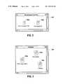
- FIG. 1Cprovides a Desktop window graphical user interface (GUI) that a system administrator will see when administering storage enclosures over the enterprise network from a computer having a client component, in accordance with one embodiment of the present invention.
- GUIdesktop window graphical user interface
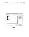
- FIG. 2illustrates an Unconfigured Hardware window that gives a user immediate access to a filtered list of hardware that has not been fully configured.
- FIG. 3provides a graphical representation of Templates, which are used to quickly and easily configure hardware, in accordance with one embodiment of the present invention.
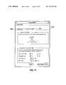
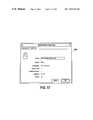
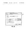
- FIG. 4illustrates a Template window, in accordance with one embodiment of the present invention.
- FIG. 5illustrates an Enterprise Monitor window, in accordance with one embodiment of the present invention.
- FIG. 6illustrates a Drive Failure window, in accordance with one embodiment of the present invention.
- FIG. 7illustrates an Enterprise Monitor window, in accordance with one embodiment of the present invention.
- FIG. 8illustrates a Monitoring Settings window, in accordance with one embodiment of the present invention.
- FIG. 9illustrates another Monitoring Setting window, in accordance with one embodiment of the present invention.
- FIG. 10illustrates an Array Modifier window, in accordance with one embodiment of the present invention.
- FIG. 11illustrates another Array Modifier window, in accordance with one embodiment of the present invention.
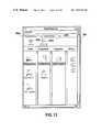
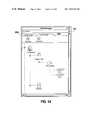
- FIGS. 12–15illustrate Enterprise windows, in accordance with one embodiment of the present invention.
- FIGS. 16–20illustrate Properties windows, in accordance with one embodiment of the present invention.
- FIG. 21illustrates a Notification window, in accordance with one embodiment of the present invention.
- FIG. 22illustrates a Users window, in accordance with one embodiment of the present invention.
- FIGS. 23–25illustrate Notification Settings windows, in accordance with one embodiment of the present invention.
- FIGS. 26 and 27illustrate Array Builder windows, in accordance with one embodiment of the present invention.
- FIGS. 28 and 29illustrate Select Drives windows, in accordance with one embodiment of the present invention.
- an easy-to-administer hardware and software storage solution for use with computer server systemsor clusters
- the softwareallows users to easily configure, manage, and monitor RAID-based disk arrays in an Enterprise.
- an enterprisemay include an example company which may have several server computer systems and RAID-based disk arrays resident at selected ones of the several computer systems.
- a standalone storage enclosurecan be used to house the RAID-based disk arrays.
- the storage enclosure of the present inventionpreferably includes dual power supplies, dual fans, one or two hardware RAID controllers, environmental sensing and monitoring devices, and associated configuration hardware.
- the drives that make up the RAID-based disk arraysare hot pluggable via SCA connectors. This provides the advantage of not necessitating additional interconnect cabling within the storage enclosure.
- the embodiments of the present inventionalso enable environmental monitoring of the storage enclosures that are connected over the network.
- the environmental monitoringmay include monitoring the temperature, monitoring fan operation, monitoring power supply operation, monitoring drive insertion and removal, and general enclosure health with regard to performing system I/O for customer applications.
- the software functional implementationis preferably based on a client-server model, and includes a variety of features for allowing system administrators to remotely configure and monitor RAID arrays, controllers, and associated subsystem components.
- the client softwarewhen loaded onto a computer of the enterprise, provides the user the power to administer storage enclosures connected to servers having the server component.
- FIG. 1Aillustrates a computer block diagram 100 of an enterprise network, in accordance with one embodiment of the present invention.
- the enterprise network 102may have a plurality of server computer systems 104 a through 104 d .
- each of the server computer systems 104may serve to provide access to groups of users in the enterprise and to share data stored on those computer systems (or clusters).
- a clusteris a collection of two or more independent servers that are able to access a common body of data storage and provide services to a common set of clients.
- the server computer systemsmay have one or more storage enclosures 106 a through 106 g which serve to house a plurality of hard disk drives.
- the storage enclosures, as used herein,are preferably RAID-based disk arrays.
- a client computer 108Also shown connected to the enterprise network 102 is a client computer 108 .
- the method by which the hardware and software control the various RAID-based disk arrays in the enterprisewill be described with reference to the following figures.
- the software used to administer the RAID-based disk arrayswill be in the form of a server component and a client component. For instance, if the storage administrator desires to configure, monitor, or service one of the storage enclosures connected to one of the server computer systems on the enterprise network 102 , the administrator can simply log on to any computer having the client component.
- the administratorcan administer any of the storage enclosures in the enterprise network 102 via any computer having the client component software.
- server computers 104 a , 104 b , 104 d , and 108all have the client component. Accordingly, the client component will allow the administrator to log-on to the enterprise network through the easy-to-use graphical user interface of the present invention and administer any of the storage enclosures.
- the server computers having associated storage enclosures that are desired to be managed by the software administration system of the present inventionshould have the server component of the software.
- server component of the softwarewill essentially allow the server computer to intelligently communicate to the various storage enclosures connected thereto.
- server computer 104 bwill have the server component which will enable it to share and make accessible the storage enclosures 106 b , 106 c , and 106 d to the enterprise network.
- server computers 104 c , 104 d , and 104 aall include the server component of the software that will enable the enterprise network to see the various storage enclosures connected to those server computers. Accordingly, the system administrator can now log-on to any computer having the client software and gain access to the enterprise network and monitor, configure, and service any of the storage enclosures including any of its individual hard drives from the client environment.
- the graphical user interface provided by the client softwarewill enable a user to easily modify any of the disk arrays connected to the enterprise network, monitor all of the storage enclosures and selected disks connected to the storage enclosures, build specific RAID array configurations, and be alerted by an event notifier of when a problem is detected with a particular storage enclosure 106 or a particular disk that is within a particular storage enclosure.
- FIG. 1Billustrates an exemplary embodiment of the storage enclosure 106 in accordance with the invention.
- the storage enclosureincludes first and second fans 110 a and 110 b , dual power supplies 114 a and 114 b , and preferably one or two hardware RAID controllers 120 .
- the storage enclosurealso includes AC power connectors 118 a and 118 b , and associated power switches 116 a and 116 b .
- a number of indicator lights/icons 121 – 126are provided on the front door of the storage enclosure 106 .
- the example indicatorsinclude a temperature indicator 121 , a fan indicator 122 , a controller indicator 123 , a driver indicator 124 , a power supply indicator 125 and a general fault indicator 126 .
- these indicatorsare merely exemplary in nature, and other indicators and icons can also be used to quickly provide a user an overview of the storage enclosure's operation.
- 20 hard disk drivesare provided.
- 20 hard disk drivesmay be 20 1-inch wide drives.
- 12 hard disk drivesare provided, each of the 12 hard disk drives may be 1.6 inches wide.
- the storage enclosure 106can be configured in Pedestal form, Rack form or in a Stackable form.
- the storage enclosure 106can also include Fibre Channel hubs, which enable the storage enclosures to provide high data transfer rates.
- Fibre Channel hubscan vary depending upon the desired data transfer rate (e.g., 100 MB per second, 1000 MB per second, etc.).
- GUIgraphical user interface
- FIG. 1Cprovides a Desktop window 150 graphical user interface (GUI) that a system administrator (i.e., user) will see when administering storage enclosures over the enterprise network from a computer having the client component.
- GUIgraphical user interface
- a system administratori.e., user
- the first window that opensis the Desktop window 150 of FIG. 1C .
- the Desktop window 150provides users immediate access to an overview of the functionality provided by the storage administration system.
- the Desktop window 150provides a user with quick and visually salient access to the basic functional tools and links.
- the functional toolsinclude an Array Modifier 152 , an Enterprise Monitor 154 , an Array Builder 156 , and an Event Notifier 158 . Also provided is a view of the network enterprise 102 , a list of Unconfigured Hardware 162 , and Templates 164 that can be used to quickly configure hardware.
- the Desktop window 150therefore provides a user with powerful functional shortcuts, like dropping an icon of a configuration template 164 on top of an icon of unconfigured hardware (e.g., a storage enclosure 106 ). It also allows users to drag objects from an Enterprise window 200 (e.g., as shown in FIGS. 12–15 ) to the Desktop window 150 to create shortcuts to those objects. For example, a user could drag a storage enclosure 106 from the Enterprise window 200 to the Desktop window 105 and a shortcut icon would be created on the Desktop window that points to the original storage enclosure 106 . Double-clicking the shortcut icon for the storage enclosure 106 will open the enterprise window 200 with that item highlighted.
- an Enterprise window 200e.g., as shown in FIGS. 12–15
- Double-clicking the ArrayModifier 152 iconwill open the ArrayModifier window 152 a of FIG. 10 .
- Double-clicking on the EnterpriseMonitor 154will open the EnterpriseMonitor window 154 ′ of FIG. 5 .
- Double-clicking on the ArrayBuilder 156will open the ArrayBuilder window 156 a of FIG. 26 .
- Double-clicking the EventNotifier 158will open the EventNotifier window 158 a of FIG. 21 .
- Double-clicking the Enterprise icon 160will open a window 200 with an overview of all the objects in the enterprise. In FIG. 12 , a tree view 200 c is illustrated.
- the window 200can also be shown in a quick view 200 d , which is illustrated in FIG. 13 .
- Double-clicking the ‘unconfigured hardware’ container 162 of FIG. 1Bwill open a window that will have representations of all partially or fully unconfigured host systems, which are shown in FIG. 2 .
- a host systemis preferably a server computer system 104 , which may have one or more storage enclosures 106 connected thereto.
- Double-clicking the templates container 164will open a window that will show the user representations of all available templates as illustrated in FIG. 3 .
- any objecte.g., a host, a drive, a storage container (e.g., a subsystem), an array, or a controller
- the context menu for that objectwith the appropriate menu items.
- the “properties” menu itemwill open a corresponding window that will display the properties for the object that was right-clicked. These properties are respectively shown in FIGS. 16–20 .
- the unconfigured hardware window 162 ′gives a user immediate access to a filtered list that preferably only has hardware that has not been fully configured (i.e., storage enclosures 106 with unassigned hard drives), instead of requiring that the user always navigate through an entire tree to find the hardware of interest.
- two storage enclosures 162 a and 162 bare shown to have unassigned hard drives. From this window, the user can also double-click a hardware representation (i.e., a storage enclosure), and the storage enclosure will open the enterprise window 200 with the selected item highlighted in the tree.
- FIG. 3provides a graphical representation of templates, which are used to quickly and easily configure hardware, in accordance with one embodiment of the present invention. More specifically, a user is provided with immediate access to templates that can be used to quickly build a RAID array from the unconfigured hardware. In one embodiment of the present invention, a template is used to specify all parameters and settings that are required to build a RAID array, with the exception of selecting the actual disks to use in the array. A more detailed view of a RAID template is provided in FIG. 4 , which shows general information 170 a about the template and associated features 170 b.
- templatesprovide a faster and simpler way for users to build an array without being presented with all of these settings.
- the usercan drag and drop a template on the icon of an unconfigured storage enclosure 106 , drag and drop a storage enclosure icon on the template, apply the template to a storage enclosure from the context menu, or choose a template from the list of templates in the Array Builder window 156 a of FIG. 26 .
- the useris then presented with a confirmation dialog that allows the user to select the drives to be used in the array, and then click Build Array 280 to finish as shown in FIG. 28 .
- the administration systemwill open the template window 170 of FIG. 4 .
- a useris able to see the settings specified by a specific template for building an array. Note that users will have access to guidance information in each dialog by clicking Show Guidance Information 171 . This will provide more information and explanations of the settings and terms used in that dialog.
- FIG. 5illustrates an EnterpriseMonitor window 154 ′, which gives users an immediate overview of the health of their entire enterprise network 102 (i.e., in a summary format).
- This windowis designed so that it will take up minimum real estate on a user's screen.
- a system administratoris able work on his computer (having the client component) other non-administration tasks while the window 154 ′ is moved to a free space of the screen.
- the system administratorcan be manually viewing the status of the enterprise (or arrays that the administrator is assigned to service). If a failure is reported via this window, the administrator can stop working on his current job and move to resolve the failure. Accordingly, the user can dismiss or minimize all other windows of the application and leave this monitor running in a corner of the screen.
- a window 180 of FIG. 6will pop up informing the user/system administrator about the error. If the user clicks on the settings button, the window of FIG. 8 will be displayed. Via the exemplary GUI of FIG. 6 , the user will be provided with immediate notification of when a failure occurs. To further assist the user, information necessary to address the failure (e.g., what happened, where, and when) is provided in 180 a and 180 b . The user can click OK to dismiss the alert and then the Enterprise Monitor will display an LED and string indicating the number of failures that have been acknowledged, but haven't been addressed yet. For instance, FIG. 7 illustrates an Enterprise Monitor 154 ′, which provides a user with feedback that an acknowledged failure still exists.
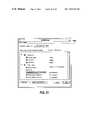
- a Monitoring Settings for Enterprise Monitor window 154 ais provided. Through this window, a user is allowed to specify which variables to display and monitor in the Enterprise Monitor and any settings for those variables. As shown, an Enterprise Monitor tab 154 a and a custom monitor tab 154 c are provided to enable the user to gain access to additional monitoring information. In the Enterprise Monitor tab 154 a , for example, a failure indicator, a disk capacity indicator, an enclosure temperature indicator, a battery heath indicator, and a power supply heath indicator are shown. By customizing these monitors, the Enterprise Monitor 154 ′ can be tailored to the needs of the responsibilities of each system administrator.
- the customize window 154 cis shown having a plurality of exemplary settings for building custom monitor window.
- this controlallow users to create a custom monitor window for any object in the enterprise network 102 (e.g., a storage enclosure). This also allows users to specify which variables to display and monitor in the custom monitor window and any settings for those variables.
- FIG. 10shows an ArrayModifier window 152 a , which allows users to add capacity to an array online and to tweak drive cache parameters of an array. By clicking the “Add Disk to Array” button, the software will display a progress window.
- FIG. 11shows another view of the ArrayModifier window 152 a , having the tweak parameters tab 152 c selected.
- the softwareBy clicking the “Revert” button, the software will set the parameters in this window back to the state when the window was opened last. Further, by clicking “Apply Parameters to Array” will dismiss this window and bring up a progress window.
- FIG. 12shows an exemplary Enterprise window 200 , having tabs 200 a and 200 b for selecting either physical devices or logical devices.
- the useris given an overview of the physical objects in the enterprise (e.g., hosts, storage enclosures, controllers, hard drives), their containment, etc.
- the usercan access the functionality, like Build Array, using a right click menu. If the user double-clicks an object, a window that shows the object's properties, e.g., as shown in FIG. 16 , will be displayed. If the user right-clicks an object, a context sensitive menu for the object will also be displayed. If the user clicks on the logical devices tab 200 b , the system will open the window of FIG. 14 . If the user clicks on the quick view button 200 d , the window of FIG. 13 will be displayed.
- the logical devices tab 200 bthe system will open the window of FIG. 14 .
- the quick view button 200 dthe window of FIG. 13 will be displayed.
- FIG. 13therefore represents a quick view of the enterprise 200 .
- this viewprovides a better overview of all the objects in the network enterprise 102 and allows the user to navigate faster through a large hierarchy of items. For instance, the user can see more hosts (i.e., server computers 104 ) at one time in the list and quickly navigate the hierarchy to see the storage enclosures 106 , controllers, and drives. The user may select a host from the list of hosts and then will see a list of all of the storage enclosures attached to that host. The user can then select a storage enclosure (i.e., subsystem) from the list and then see a list of the controllers in that storage enclosure (e.g., a single controller, or two controllers in a dual controller hardware configuration). The user is then able to select a controller and see a list of the drives that it controls.
- hostsi.e., server computers 104
- the usermay select a host from the list of hosts and then will see a list of all of the storage enclosures attached to that host
- Double-clicking an item in any of the columnswill cause the contents of the item to be displayed.
- Right-clicking on an objectwill cause a context sensitive menu for the object to be displayed.
- FIG. 14a user is allowed to see logical devices in the enterprise (e.g., Arrays).
- FIG. 15provides a quick view of the logical devices of the enterprise, in accordance with one embodiment of the present invention. For example, this view allows a user to see the logical devices in the enterprise. It provides a better overview of all the objects in the enterprise and allows the user to navigate faster through a large hierarchy of items. Further, the user can see more hosts at one time in the list and quickly navigate the hierarchy to see the subsystems (i.e., storage enclosures 106 ), controllers, and arrays. The user can select a host from the list of hosts and will then see a list of all of the subsystems attached to that host.
- subsystemsi.e., storage enclosures 106
- the userselects a subsystem from the list of subsystems and will see a list of the controllers in that subsystem (e.g., a single controller, or two controllers in a dual controller hardware configuration). The user then selects a controller and will see a list of the arrays that it controls.
- a subsysteme.g., a single controller, or two controllers in a dual controller hardware configuration.
- the userselects a controller and will see a list of the arrays that it controls.
- FIG. 16provides a host properties window 202 .
- the hostis Waterloo. This host has its properties, such as, vendor, protocol type, address, and operating system clearly displayed for the user to see.
- FIG. 17is a subsystem properties window 204 , which identifies an exemplary storage enclosure and the host it is connected to.
- FIG. 18shows a controller properties window 206 .
- the controller cardis an Adaptec, Inc. RAID controller Card that is connected via a SCSI interface.
- FIG. 19shows a drive properties window 208 . All of the important drive properties are provided so that the user/administrator can quickly identify the drive characteristics.
- FIG. 20shows an array properties window 210 , which shows the RAID level, the vendor, the drives, the capacity, the free space, and the status.
- FIG. 21shows an even notification window 158 a , in accordance with one embodiment of the present invention.
- the useris allowed to see and specify the event notification settings for a specific host object. If the user clicks the host pop-up menu at the top of the window, the user can select any host (e.g., a computer having the server component) in the enterprise in order to see and specify its notification settings.
- the usercan select the events for which the user wants notifications sent for a particular host. Events can be collapsed into two groups (Fatal Events and Critical Events) and then notification can be quickly specified for those events as a whole. Otherwise, the groups can be disclosed and display all of the events in the group, which enables the user to specify notification separately for each individual event.
- a windowis opened that lists the users as shown in FIG. 22 . If the user double-clicks an event or clicks Specify Event Notification, a window is opened that allows the user to specify the notification settings for that event, such as who gets notified and how, as illustrated in FIG. 25 .
- FIG. 22shows the users window 250 , which allows viewing and modification of the users list.
- existing accountscan be viewed and edited in a simplistic manner through window 250 .
- a windowis opened that allows the user to specify a new user account and its notification settings as shown in FIG. 23 .
- the user double-clicks a user or clicks the Edit User buttona window is opened that allows the user to edit the selected user's account information as shown in FIG. 24 .
- the user clicks the Delete User buttonthe selected user is removed from the list. In a preferred embodiment, the user is only deleted after confirming the deletion.
- the OK buttonaccepts changes and closes the window.
- the Cancel buttoncloses the window without saving changes.
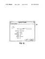
- FIG. 23shows a notification settings window 252 for a new user. As shown, a user is allowed to create a new user account and the notification methods established (e.g., pager number, email addresses, etc.).
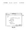
- FIG. 24illustrates a notification settings window 254 with the settings for a user, Bob Lewis. Through this window, a user is allowed to see and edit the notification methods for a user account.
- FIG. 25illustrates an Event notification window 256 for a controller failure, in accordance with one embodiment of the present invention.
- this windowallows a user to see and specify the event notification settings for a specific event (e.g., controller card failures). The entire list of users is displayed and the user can select which users to notify for the event (e.g., Bob Lewis) and how they should be notified (e.g., by Pager 1).
- FIG. 26shows an ArrayBuilder window 156 a .
- a useris allowed to build an array for the selected subsystem by using a template.
- the top container in the windowprovides the user with a list of unconfigured subsystems.
- the bottom containerlists available templates.
- Select Drivesthe user is allowed to specify the drives to be used for the array as shown in FIGS. 28 and 29 .
- FIG. 27illustrates an ArrayBuilder window 156 a , through which a more experienced user can build an array from scratch.
- a useris allowed to build an array for the selected subsystem “manually” by specifying each parameter.
- the windowalso shows a build-from template tab 156 b and a build from scratch tab 156 c .
- the top container in the windowprovides the user with a list of unconfigured subsystems. By clicking Select Drives, a user is allowed to specify the drives to be used for the array as shown in FIGS. 28 and 29 .
- FIG. 28shows a select drives window 280 , which allows a user to review the array specification and select specific drives before building the array.
- a select drives window 280By clicking Build Array, the user can initiate the build process and can open a modeless progress window. Clicking Show Details reveals more array specification parameters as shown in FIG. 29 .
- FIG. 29shows a select drives window 280 ′, with details 181 shown.
- the usersare allowed to review the array specification and select specific drives before building the array.
- Clicking Build Arrayinitiates the build process and opens a modeless progress window.
- Clicking Hide Detailshides the detailed array specification parameters as shown in FIG. 28 .
- the inventionemploys various computer-implemented operations involving data stored in computer systems to drive software applications and hardware devices. These operations are those requiring physical manipulation of physical quantities. Usually, though not necessarily, these quantities take the form of electrical or magnetic signals capable of being stored, transferred, combined, compared, and otherwise manipulated. Further, the manipulations performed are often referred to in terms, such as producing, identifying, determining, or comparing.
- the inventionalso relates to a device or an apparatus for performing these operations.
- the apparatusmay be specially constructed for the required purposes, or it may be a general purpose computer selectively activated or configured by a computer program stored in the computer.
- various general purpose machinesmay be used with computer programs written in accordance with the teachings herein, or it may be more convenient to construct a more specialized apparatus to perform the required operations.
Landscapes
- Engineering & Computer Science (AREA)
- Computer Networks & Wireless Communication (AREA)
- Signal Processing (AREA)
- Human Computer Interaction (AREA)
- Debugging And Monitoring (AREA)
Abstract
Description
Claims (17)
Priority Applications (1)
| Application Number | Priority Date | Filing Date | Title |
|---|---|---|---|
| US09/275,727US7107534B1 (en) | 1998-03-24 | 1999-03-24 | Storage area network administration |
Applications Claiming Priority (2)
| Application Number | Priority Date | Filing Date | Title |
|---|---|---|---|
| US7921298P | 1998-03-24 | 1998-03-24 | |
| US09/275,727US7107534B1 (en) | 1998-03-24 | 1999-03-24 | Storage area network administration |
Publications (1)
| Publication Number | Publication Date |
|---|---|
| US7107534B1true US7107534B1 (en) | 2006-09-12 |
Family
ID=36951967
Family Applications (1)
| Application Number | Title | Priority Date | Filing Date |
|---|---|---|---|
| US09/275,727Expired - LifetimeUS7107534B1 (en) | 1998-03-24 | 1999-03-24 | Storage area network administration |
Country Status (1)
| Country | Link |
|---|---|
| US (1) | US7107534B1 (en) |
Cited By (51)
| Publication number | Priority date | Publication date | Assignee | Title |
|---|---|---|---|---|
| US20020175938A1 (en)* | 2001-05-22 | 2002-11-28 | Hackworth Brian M. | System and method for consolidated reporting of characteristics for a group of file systems |
| US20030009444A1 (en)* | 2001-06-14 | 2003-01-09 | Eidler Christopher William | Secured shared storage architecture |
| US20030055972A1 (en)* | 2001-07-09 | 2003-03-20 | Fuller William Tracy | Methods and systems for shared storage virtualization |
| US20040186860A1 (en)* | 2003-03-21 | 2004-09-23 | Wen-Hsin Lee | Method and architecture for providing data-change alerts to external applications via a push service |
| US20050033914A1 (en)* | 1998-12-22 | 2005-02-10 | Hitachi, Ltd. | Disk storage system |
| US20050050471A1 (en)* | 2003-08-26 | 2005-03-03 | Hallisey Brian Scott | Methods of displaying resources of overlapping but separate hierarchies |
| US20050114590A1 (en)* | 2003-11-26 | 2005-05-26 | Jan Klier | Drive controller user interface |
| US20050160378A1 (en)* | 2004-01-20 | 2005-07-21 | Fujitsu Limited | Configuration display apparatus for computer, computer configuration display method, and computer configuration display program |
| US20050182831A1 (en)* | 2004-01-20 | 2005-08-18 | Fujitsu Limited | Configuration display apparatus for computer, computer configuration display method, and computer configuration display program |
| US20060095664A1 (en)* | 2004-10-30 | 2006-05-04 | James Wichelman | Systems and methods for presenting managed data |
| US20060107218A1 (en)* | 2006-01-17 | 2006-05-18 | Microsoft Corporation | View-based navigation model for graphical user interfaces |
| US20060168477A1 (en)* | 2005-01-24 | 2006-07-27 | International Business Machines Corporation | Multilayered architecture for storage protocol conformance testing of storage devices |
| US20060277363A1 (en)* | 2005-05-23 | 2006-12-07 | Xiaogang Qiu | Method and apparatus for implementing a grid storage system |
| US7197545B1 (en)* | 2000-08-28 | 2007-03-27 | Sanavigator, Inc. | Techniques for dynamically loading modules for devices discovered in a storage network |
| US20070094370A1 (en)* | 2005-10-26 | 2007-04-26 | Graves David A | Method and an apparatus for automatic creation of secure connections between segmented resource farms in a utility computing environment |
| US7228353B1 (en) | 2002-03-28 | 2007-06-05 | Emc Corporation | Generating and launching remote method invocation servers for individual client applications |
| US20070168611A1 (en)* | 2003-11-28 | 2007-07-19 | Hironori Yasukawa | Storage system and method for a storage control apparatus using information on management of storage resources |
| US20070214412A1 (en)* | 2002-09-30 | 2007-09-13 | Sanavigator, Inc. | Method and System for Generating a Network Monitoring Display with Animated Utilization Information |
| US7293272B1 (en) | 2004-02-26 | 2007-11-06 | Veritas Operating Corporation | Device driver processing for automated system restores |
| US20070260712A1 (en)* | 2006-05-03 | 2007-11-08 | Jibbe Mahmoud K | Configuration verification, recommendation, and animation method for a disk array in a storage area network (SAN) |
| US7313719B1 (en) | 2004-02-06 | 2007-12-25 | Symantec Operating Corporation | Restore of backup to computer system with filesystem/volume attribute modification |
| US7322010B1 (en)* | 2004-02-06 | 2008-01-22 | Symantec Operating Corporation | Graphical user interface for mapping computer resources |
| US7334157B1 (en) | 2004-02-26 | 2008-02-19 | Symantec Operating Corporation | Restore of data to a computer system having different hardware |
| US7350149B1 (en)* | 2002-03-28 | 2008-03-25 | Emc Corporation | Backup reporting framework graphical user interface |
| US7404145B1 (en)* | 2002-03-28 | 2008-07-22 | Emc Corporation | Generic mechanism for reporting on backups |
| US20080189637A1 (en)* | 2006-10-16 | 2008-08-07 | Invensys Systems, Inc. | Data quality and status behavior for human machine interface graphics in industrial control and automation systems |
| US20090013258A1 (en)* | 2000-09-11 | 2009-01-08 | International Business Machines Corporation | Pictorial-based user interface management of computer hardware components |
| US7577724B1 (en)* | 2006-03-28 | 2009-08-18 | Emc Corporation | Methods and apparatus associated with advisory generation |
| US20090222733A1 (en)* | 2008-02-28 | 2009-09-03 | International Business Machines Corporation | Zoning of Devices in a Storage Area Network with LUN Masking/Mapping |
| US20090249213A1 (en)* | 2008-03-31 | 2009-10-01 | Atsushi Murase | User interface providing information system topology presentation |
| US20090254863A1 (en)* | 2008-04-03 | 2009-10-08 | Dell Products L.P. | Systems and Methods for Accessing System Utilities |
| US7680957B1 (en) | 2003-05-09 | 2010-03-16 | Symantec Operating Corporation | Computer system configuration representation and transfer |
| US7689587B1 (en)* | 2007-06-28 | 2010-03-30 | Emc Corporation | Autorep process to create repository according to seed data and at least one new schema |
| US7702948B1 (en)* | 2004-07-13 | 2010-04-20 | Adaptec, Inc. | Auto-configuration of RAID systems |
| US7739614B1 (en)* | 2001-05-22 | 2010-06-15 | Netapp, Inc. | System and method for consolidated reporting of characteristics for a group of directories |
| US7769990B1 (en) | 2007-03-23 | 2010-08-03 | Symantec Corporation | Using a monitoring process to update system configuration settings during restore operations |
| US7886185B1 (en) | 2007-03-23 | 2011-02-08 | Symantec Corporation | Creation of a device database and synthesis of device driver information during dissimilar system restore |
| US7895520B1 (en)* | 2006-01-03 | 2011-02-22 | Emc Corp | Methods and apparatus for managing scheduled activities in a storage area network |
| US20110055711A1 (en)* | 2006-04-20 | 2011-03-03 | Jaquot Bryan J | Graphical Interface For Managing Server Environment |
| US7979701B1 (en) | 2006-09-15 | 2011-07-12 | Netapp, Inc. | Cross mapping graphical interface to show encryption relationships between hosts and storage devices |
| US8132186B1 (en) | 2007-03-23 | 2012-03-06 | Symantec Corporation | Automatic detection of hardware and device drivers during restore operations |
| US20120324354A1 (en)* | 2011-06-15 | 2012-12-20 | Chipperfield John Stuart | Computer system |
| US20130047030A1 (en)* | 2011-08-18 | 2013-02-21 | Hitachi, Ltd. | Storage apparatus and power supply method |
| US9122711B1 (en) | 2012-05-24 | 2015-09-01 | Symantec Corporation | Simplified system backup protection and recovery |
| US9170737B1 (en)* | 2009-09-30 | 2015-10-27 | Emc Corporation | Processing data storage system configuration information |
| US9460399B1 (en) | 2013-12-30 | 2016-10-04 | Emc Corporation | Dynamic event driven storage system optimization |
| US20180052623A1 (en)* | 2016-08-22 | 2018-02-22 | Amplidata N.V. | Automatic RAID Provisioning |
| US9929893B2 (en)* | 2009-12-09 | 2018-03-27 | Citrix Systems, Inc. | Methods and systems for displaying, on a first machine, data associated with a drive of a second machine, without mapping the drive |
| US10867358B2 (en)* | 2016-10-28 | 2020-12-15 | Flexiwage Limited | Employee determined payroll payment processing method and system |
| US11223537B1 (en) | 2016-08-17 | 2022-01-11 | Veritas Technologies Llc | Executing custom scripts from the host during disaster recovery |
| US20240020044A1 (en)* | 2022-07-15 | 2024-01-18 | Fulian Precision Electronics (Tianjin) Co., Ltd. | Method for locating hard disk, system and server |
Citations (9)
| Publication number | Priority date | Publication date | Assignee | Title |
|---|---|---|---|---|
| US5829053A (en)* | 1996-05-10 | 1998-10-27 | Apple Computer, Inc. | Block storage memory management system and method utilizing independent partition managers and device drivers |
| US5890204A (en)* | 1996-06-03 | 1999-03-30 | Emc Corporation | User controlled storage configuration using graphical user interface |
| US6009466A (en)* | 1997-10-31 | 1999-12-28 | International Business Machines Corporation | Network management system for enabling a user to configure a network of storage devices via a graphical user interface |
| US6098119A (en)* | 1998-01-21 | 2000-08-01 | Mylex Corporation | Apparatus and method that automatically scans for and configures previously non-configured disk drives in accordance with a particular raid level based on the needed raid level |
| US6151620A (en)* | 1997-10-22 | 2000-11-21 | Novell, Inc. | Conference messaging system |
| US6263350B1 (en)* | 1996-10-11 | 2001-07-17 | Sun Microsystems, Inc. | Method and system for leasing storage |
| US6266721B1 (en)* | 1997-05-13 | 2001-07-24 | Micron Electronics, Inc. | System architecture for remote access and control of environmental management |
| US6269398B1 (en)* | 1993-08-20 | 2001-07-31 | Nortel Networks Limited | Method and system for monitoring remote routers in networks for available protocols and providing a graphical representation of information received from the routers |
| US6269397B1 (en)* | 1997-05-05 | 2001-07-31 | Nokia Networks Oy | System and method for network element management in a Telecommunications network |
- 1999
- 1999-03-24USUS09/275,727patent/US7107534B1/ennot_activeExpired - Lifetime
Patent Citations (9)
| Publication number | Priority date | Publication date | Assignee | Title |
|---|---|---|---|---|
| US6269398B1 (en)* | 1993-08-20 | 2001-07-31 | Nortel Networks Limited | Method and system for monitoring remote routers in networks for available protocols and providing a graphical representation of information received from the routers |
| US5829053A (en)* | 1996-05-10 | 1998-10-27 | Apple Computer, Inc. | Block storage memory management system and method utilizing independent partition managers and device drivers |
| US5890204A (en)* | 1996-06-03 | 1999-03-30 | Emc Corporation | User controlled storage configuration using graphical user interface |
| US6263350B1 (en)* | 1996-10-11 | 2001-07-17 | Sun Microsystems, Inc. | Method and system for leasing storage |
| US6269397B1 (en)* | 1997-05-05 | 2001-07-31 | Nokia Networks Oy | System and method for network element management in a Telecommunications network |
| US6266721B1 (en)* | 1997-05-13 | 2001-07-24 | Micron Electronics, Inc. | System architecture for remote access and control of environmental management |
| US6151620A (en)* | 1997-10-22 | 2000-11-21 | Novell, Inc. | Conference messaging system |
| US6009466A (en)* | 1997-10-31 | 1999-12-28 | International Business Machines Corporation | Network management system for enabling a user to configure a network of storage devices via a graphical user interface |
| US6098119A (en)* | 1998-01-21 | 2000-08-01 | Mylex Corporation | Apparatus and method that automatically scans for and configures previously non-configured disk drives in accordance with a particular raid level based on the needed raid level |
Non-Patent Citations (4)
| Title |
|---|
| M. Blaum et al., "EVENODD: An Efficient Scheme for Tolerating Double Disk Failures in RAID Architectures", pp. 192-201, 1994 IEEE Transactions on Computers, vol. 44, No. 2. |
| P. Massiglia, "The Basics of RAID Technology", pp. 1-3, (C) 1997-8 Rising Edge Technologies, Inc., www.rising-edge.com/industry/overview/raid/index.html. |
| P. Massiglia, "The RAID Book", 6<SUP>th </SUP>Ed., (C) RAID Advisory Board, Feb. 1997. |
| P. Massiglia, "What's RAID", (C) 1997-8 Advanced Technology and Systems Co., www.adtx.co.jp/english/raid/raid0.html. |
Cited By (90)
| Publication number | Priority date | Publication date | Assignee | Title |
|---|---|---|---|---|
| US20100005240A1 (en)* | 1998-12-22 | 2010-01-07 | Naoto Matsunami | Display apparatus and its method for displaying connections among a host, a logical unit and a storage system in a virtual storage system |
| US8375168B2 (en) | 1998-12-22 | 2013-02-12 | Hitachi, Ltd. | Method and system of collection performance data for storage network |
| US7937527B2 (en)* | 1998-12-22 | 2011-05-03 | Hitachi, Ltd. | Storage system for sending an access request from a host to a storage subsystem |
| US20050033914A1 (en)* | 1998-12-22 | 2005-02-10 | Hitachi, Ltd. | Disk storage system |
| US8176248B2 (en) | 1998-12-22 | 2012-05-08 | Hitachi, Ltd. | Method and system of collection performance data for storage network |
| US8051244B2 (en) | 1998-12-22 | 2011-11-01 | Hitachi, Ltd. | Storage system for sending an access request from a host to a storage subsystem |
| US7805564B2 (en)* | 1998-12-22 | 2010-09-28 | Hitachi, Ltd. | Display apparatus and its method for displaying connections among a host, a logical unit and a storage system in a virtual storage system |
| US7197545B1 (en)* | 2000-08-28 | 2007-03-27 | Sanavigator, Inc. | Techniques for dynamically loading modules for devices discovered in a storage network |
| US7669139B2 (en)* | 2000-09-11 | 2010-02-23 | International Business Machines Corporation | Pictorial-based user interface management of computer hardware components |
| US7512894B1 (en)* | 2000-09-11 | 2009-03-31 | International Business Machines Corporation | Pictorial-based user interface management of computer hardware components |
| US20090013258A1 (en)* | 2000-09-11 | 2009-01-08 | International Business Machines Corporation | Pictorial-based user interface management of computer hardware components |
| US7739614B1 (en)* | 2001-05-22 | 2010-06-15 | Netapp, Inc. | System and method for consolidated reporting of characteristics for a group of directories |
| US8171414B2 (en)* | 2001-05-22 | 2012-05-01 | Netapp, Inc. | System and method for consolidated reporting of characteristics for a group of file systems |
| US20020175938A1 (en)* | 2001-05-22 | 2002-11-28 | Hackworth Brian M. | System and method for consolidated reporting of characteristics for a group of file systems |
| US7693970B2 (en) | 2001-06-14 | 2010-04-06 | Savvis Communications Corporation | Secured shared storage architecture |
| US20030009444A1 (en)* | 2001-06-14 | 2003-01-09 | Eidler Christopher William | Secured shared storage architecture |
| US7734781B2 (en)* | 2001-07-09 | 2010-06-08 | Savvis Communications Corporation | Methods and systems for shared storage virtualization |
| US20030055972A1 (en)* | 2001-07-09 | 2003-03-20 | Fuller William Tracy | Methods and systems for shared storage virtualization |
| US7228353B1 (en) | 2002-03-28 | 2007-06-05 | Emc Corporation | Generating and launching remote method invocation servers for individual client applications |
| US8051378B1 (en)* | 2002-03-28 | 2011-11-01 | Emc Corporation | Generic mechanism for reporting on backups |
| US7404145B1 (en)* | 2002-03-28 | 2008-07-22 | Emc Corporation | Generic mechanism for reporting on backups |
| US20080134050A1 (en)* | 2002-03-28 | 2008-06-05 | Franceschelli Anthony J | Backup Reporting Framework Graphical User Interface |
| US20070198728A1 (en)* | 2002-03-28 | 2007-08-23 | Franceschelli Anthony J Jr | Generating and launching remote method invocation servers for individual client applications |
| US7810034B2 (en) | 2002-03-28 | 2010-10-05 | Emc Corporation | Backup reporting framework graphical user interface |
| US7350149B1 (en)* | 2002-03-28 | 2008-03-25 | Emc Corporation | Backup reporting framework graphical user interface |
| US20070214412A1 (en)* | 2002-09-30 | 2007-09-13 | Sanavigator, Inc. | Method and System for Generating a Network Monitoring Display with Animated Utilization Information |
| US8862998B2 (en) | 2002-09-30 | 2014-10-14 | Brocade Communications Systems, Inc. | Method and system for generating a network monitoring display with animated utilization information |
| US9448860B2 (en)* | 2003-03-21 | 2016-09-20 | Oracle America, Inc. | Method and architecture for providing data-change alerts to external applications via a push service |
| US20040186860A1 (en)* | 2003-03-21 | 2004-09-23 | Wen-Hsin Lee | Method and architecture for providing data-change alerts to external applications via a push service |
| US7680957B1 (en) | 2003-05-09 | 2010-03-16 | Symantec Operating Corporation | Computer system configuration representation and transfer |
| US8051389B2 (en)* | 2003-08-26 | 2011-11-01 | Hewlett-Packard Development Company, L.P. | Methods of displaying resources of overlapping but separate hierarchies |
| US20050050471A1 (en)* | 2003-08-26 | 2005-03-03 | Hallisey Brian Scott | Methods of displaying resources of overlapping but separate hierarchies |
| US20050114590A1 (en)* | 2003-11-26 | 2005-05-26 | Jan Klier | Drive controller user interface |
| US20070168611A1 (en)* | 2003-11-28 | 2007-07-19 | Hironori Yasukawa | Storage system and method for a storage control apparatus using information on management of storage resources |
| US20050182831A1 (en)* | 2004-01-20 | 2005-08-18 | Fujitsu Limited | Configuration display apparatus for computer, computer configuration display method, and computer configuration display program |
| US20050160378A1 (en)* | 2004-01-20 | 2005-07-21 | Fujitsu Limited | Configuration display apparatus for computer, computer configuration display method, and computer configuration display program |
| US7322010B1 (en)* | 2004-02-06 | 2008-01-22 | Symantec Operating Corporation | Graphical user interface for mapping computer resources |
| US7313719B1 (en) | 2004-02-06 | 2007-12-25 | Symantec Operating Corporation | Restore of backup to computer system with filesystem/volume attribute modification |
| US7334157B1 (en) | 2004-02-26 | 2008-02-19 | Symantec Operating Corporation | Restore of data to a computer system having different hardware |
| US7941814B1 (en) | 2004-02-26 | 2011-05-10 | Symantec Operating Corporation | Device driver processing for automated system restores |
| US7293272B1 (en) | 2004-02-26 | 2007-11-06 | Veritas Operating Corporation | Device driver processing for automated system restores |
| US8090981B1 (en)* | 2004-07-13 | 2012-01-03 | Pmc-Sierra, Inc. | Auto-configuration of RAID systems |
| US7702948B1 (en)* | 2004-07-13 | 2010-04-20 | Adaptec, Inc. | Auto-configuration of RAID systems |
| US7779368B2 (en)* | 2004-10-30 | 2010-08-17 | Hewlett-Packard Development Company, L.P. | Systems and methods for presenting managed data |
| US20060095664A1 (en)* | 2004-10-30 | 2006-05-04 | James Wichelman | Systems and methods for presenting managed data |
| US7661034B2 (en)* | 2005-01-24 | 2010-02-09 | International Business Machines Corporation | Multilayered architecture for storage protocol conformance testing of storage devices |
| US20060168477A1 (en)* | 2005-01-24 | 2006-07-27 | International Business Machines Corporation | Multilayered architecture for storage protocol conformance testing of storage devices |
| US20060277363A1 (en)* | 2005-05-23 | 2006-12-07 | Xiaogang Qiu | Method and apparatus for implementing a grid storage system |
| US7484039B2 (en)* | 2005-05-23 | 2009-01-27 | Xiaogang Qiu | Method and apparatus for implementing a grid storage system |
| US20070094370A1 (en)* | 2005-10-26 | 2007-04-26 | Graves David A | Method and an apparatus for automatic creation of secure connections between segmented resource farms in a utility computing environment |
| US7840902B2 (en)* | 2005-10-26 | 2010-11-23 | Hewlett-Packard Development Company, L.P. | Method and an apparatus for automatic creation of secure connections between segmented resource farms in a utility computing environment |
| US7895520B1 (en)* | 2006-01-03 | 2011-02-22 | Emc Corp | Methods and apparatus for managing scheduled activities in a storage area network |
| US20060107218A1 (en)* | 2006-01-17 | 2006-05-18 | Microsoft Corporation | View-based navigation model for graphical user interfaces |
| US7577724B1 (en)* | 2006-03-28 | 2009-08-18 | Emc Corporation | Methods and apparatus associated with advisory generation |
| US20110055711A1 (en)* | 2006-04-20 | 2011-03-03 | Jaquot Bryan J | Graphical Interface For Managing Server Environment |
| US8745503B2 (en)* | 2006-04-20 | 2014-06-03 | Hewlett-Packard Development Company, L.P. | Graphical interface for managing server environment |
| US20070260712A1 (en)* | 2006-05-03 | 2007-11-08 | Jibbe Mahmoud K | Configuration verification, recommendation, and animation method for a disk array in a storage area network (SAN) |
| US8024440B2 (en)* | 2006-05-03 | 2011-09-20 | Netapp, Inc. | Configuration verification, recommendation, and animation method for a disk array in a storage area network (SAN) |
| US8312130B2 (en) | 2006-05-03 | 2012-11-13 | Netapp, Inc. | Configuration verification, recommendation, and animation method for a disk array in a storage area network (SAN) |
| US7979701B1 (en) | 2006-09-15 | 2011-07-12 | Netapp, Inc. | Cross mapping graphical interface to show encryption relationships between hosts and storage devices |
| US20080189637A1 (en)* | 2006-10-16 | 2008-08-07 | Invensys Systems, Inc. | Data quality and status behavior for human machine interface graphics in industrial control and automation systems |
| US7769990B1 (en) | 2007-03-23 | 2010-08-03 | Symantec Corporation | Using a monitoring process to update system configuration settings during restore operations |
| US8132186B1 (en) | 2007-03-23 | 2012-03-06 | Symantec Corporation | Automatic detection of hardware and device drivers during restore operations |
| US7886185B1 (en) | 2007-03-23 | 2011-02-08 | Symantec Corporation | Creation of a device database and synthesis of device driver information during dissimilar system restore |
| US7689587B1 (en)* | 2007-06-28 | 2010-03-30 | Emc Corporation | Autorep process to create repository according to seed data and at least one new schema |
| US8930537B2 (en)* | 2008-02-28 | 2015-01-06 | International Business Machines Corporation | Zoning of devices in a storage area network with LUN masking/mapping |
| US9563380B2 (en) | 2008-02-28 | 2017-02-07 | International Business Machines Corporation | Zoning of devices in a storage area network with LUN masking/mapping |
| US20090222733A1 (en)* | 2008-02-28 | 2009-09-03 | International Business Machines Corporation | Zoning of Devices in a Storage Area Network with LUN Masking/Mapping |
| JP2013101629A (en)* | 2008-03-31 | 2013-05-23 | Hitachi Ltd | User interface providing information system topology display |
| EP2348674A1 (en)* | 2008-03-31 | 2011-07-27 | Hitachi Ltd. | User interface providing information system topology presentation |
| WO2009122626A1 (en) | 2008-03-31 | 2009-10-08 | Hitachi, Ltd. | User interface providing information system topology presentation |
| JP2014096166A (en)* | 2008-03-31 | 2014-05-22 | Hitachi Ltd | User interface providing information system topology display |
| JP2011517346A (en)* | 2008-03-31 | 2011-06-02 | 株式会社日立製作所 | User interface providing information system topology display |
| US9225610B2 (en) | 2008-03-31 | 2015-12-29 | Hitachi, Ltd. | User interface providing information system topology presentation |
| US20090249213A1 (en)* | 2008-03-31 | 2009-10-01 | Atsushi Murase | User interface providing information system topology presentation |
| US20090254863A1 (en)* | 2008-04-03 | 2009-10-08 | Dell Products L.P. | Systems and Methods for Accessing System Utilities |
| US8819563B2 (en)* | 2008-04-03 | 2014-08-26 | Dell Products L.P. | Systems and methods for accessing system utilities |
| US10489011B2 (en) | 2008-04-03 | 2019-11-26 | Dell Products L.P. | Systems and methods for accessing system utilities |
| US9170737B1 (en)* | 2009-09-30 | 2015-10-27 | Emc Corporation | Processing data storage system configuration information |
| US9929893B2 (en)* | 2009-12-09 | 2018-03-27 | Citrix Systems, Inc. | Methods and systems for displaying, on a first machine, data associated with a drive of a second machine, without mapping the drive |
| US20120324354A1 (en)* | 2011-06-15 | 2012-12-20 | Chipperfield John Stuart | Computer system |
| US20130047030A1 (en)* | 2011-08-18 | 2013-02-21 | Hitachi, Ltd. | Storage apparatus and power supply method |
| US9122711B1 (en) | 2012-05-24 | 2015-09-01 | Symantec Corporation | Simplified system backup protection and recovery |
| US9460399B1 (en) | 2013-12-30 | 2016-10-04 | Emc Corporation | Dynamic event driven storage system optimization |
| US11223537B1 (en) | 2016-08-17 | 2022-01-11 | Veritas Technologies Llc | Executing custom scripts from the host during disaster recovery |
| US20180052623A1 (en)* | 2016-08-22 | 2018-02-22 | Amplidata N.V. | Automatic RAID Provisioning |
| US10365837B2 (en)* | 2016-08-22 | 2019-07-30 | Western Digital Technologies, Inc. | Automatic RAID provisioning |
| US10867358B2 (en)* | 2016-10-28 | 2020-12-15 | Flexiwage Limited | Employee determined payroll payment processing method and system |
| US20240020044A1 (en)* | 2022-07-15 | 2024-01-18 | Fulian Precision Electronics (Tianjin) Co., Ltd. | Method for locating hard disk, system and server |
| US12061815B2 (en)* | 2022-07-15 | 2024-08-13 | Fulian Precision Electronics (Tianjin) Co., Ltd. | Method for locating hard disk, system and server |
Similar Documents
| Publication | Publication Date | Title |
|---|---|---|
| US7107534B1 (en) | Storage area network administration | |
| US6538669B1 (en) | Graphical user interface for configuration of a storage system | |
| US6654830B1 (en) | Method and system for managing data migration for a storage system | |
| JP5159421B2 (en) | Storage system and storage system management method using management device | |
| US8185707B2 (en) | Storage system and path management method for multi-host environment | |
| US7512888B2 (en) | Management method and apparatus for storage apparatus | |
| JP4723925B2 (en) | Method for controlling storage policy according to volume activity | |
| US8046469B2 (en) | System and method for interfacing with virtual storage | |
| US20050108375A1 (en) | Method and graphical user interface for managing and configuring multiple clusters of virtualization switches | |
| US7895519B1 (en) | Tracking use of interface and online assistance | |
| GB2351375A (en) | Storage Domain Management System | |
| US20070198690A1 (en) | Data Management System | |
| US20040243778A1 (en) | Representing status information in a storage subsystem copy services product | |
| JP4819358B2 (en) | Method and apparatus for managing storage devices | |
| US20050007959A1 (en) | Information processing apparatus and control method of information processing apparatus and program for the same | |
| US20130019180A1 (en) | Log collector in a distributed computing system | |
| JP4843294B2 (en) | Computer system and management computer | |
| US7983171B2 (en) | Method to manage path failure thresholds | |
| US20080147973A1 (en) | Provisioning storage | |
| US20030200487A1 (en) | Program, information processing method, information processing apparatus, and storage apparatus | |
| US20120110277A1 (en) | Method and system for storage-system management | |
| US8285835B1 (en) | Graphical analysis of states in a computing system | |
| US10721301B1 (en) | Graphical user interface for storage cluster management | |
| US7613720B2 (en) | Selectively removing entities from a user interface displaying network entities | |
| US8732688B1 (en) | Updating system status |
Legal Events
| Date | Code | Title | Description |
|---|---|---|---|
| AS | Assignment | Owner name:ADAPTEC, INC., CALIFORNIA Free format text:ASSIGNMENT OF ASSIGNORS INTEREST;ASSIGNORS:DE JONG, ANKE T.;CORNETT, LARRY L.;HOLZER, DAVID A.;AND OTHERS;REEL/FRAME:010059/0804;SIGNING DATES FROM 19930507 TO 19990609 | |
| STCF | Information on status: patent grant | Free format text:PATENTED CASE | |
| FPAY | Fee payment | Year of fee payment:4 | |
| AS | Assignment | Owner name:PMC-SIERRA, INC., CALIFORNIA Free format text:ASSIGNMENT OF ASSIGNORS INTEREST;ASSIGNOR:ADAPTEC, INC.;REEL/FRAME:030899/0567 Effective date:20100608 | |
| AS | Assignment | Owner name:BANK OF AMERICA, N.A., NORTH CAROLINA Free format text:SECURITY INTEREST IN PATENTS;ASSIGNORS:PMC-SIERRA, INC.;PMC-SIERRA US, INC.;WINTEGRA, INC.;REEL/FRAME:030947/0710 Effective date:20130802 | |
| FPAY | Fee payment | Year of fee payment:8 | |
| AS | Assignment | Owner name:PMC-SIERRA US, INC., CALIFORNIA Free format text:RELEASE BY SECURED PARTY;ASSIGNOR:BANK OF AMERICA, N.A.;REEL/FRAME:037675/0129 Effective date:20160115 Owner name:WINTEGRA, INC., CALIFORNIA Free format text:RELEASE BY SECURED PARTY;ASSIGNOR:BANK OF AMERICA, N.A.;REEL/FRAME:037675/0129 Effective date:20160115 Owner name:PMC-SIERRA, INC., CALIFORNIA Free format text:RELEASE BY SECURED PARTY;ASSIGNOR:BANK OF AMERICA, N.A.;REEL/FRAME:037675/0129 Effective date:20160115 | |
| AS | Assignment | Owner name:MORGAN STANLEY SENIOR FUNDING, INC., NEW YORK Free format text:PATENT SECURITY AGREEMENT;ASSIGNORS:MICROSEMI STORAGE SOLUTIONS, INC. (F/K/A PMC-SIERRA, INC.);MICROSEMI STORAGE SOLUTIONS (U.S.), INC. (F/K/A PMC-SIERRA US, INC.);REEL/FRAME:037689/0719 Effective date:20160115 | |
| MAFP | Maintenance fee payment | Free format text:PAYMENT OF MAINTENANCE FEE, 12TH YEAR, LARGE ENTITY (ORIGINAL EVENT CODE: M1553) Year of fee payment:12 | |
| AS | Assignment | Owner name:MICROSEMI STORAGE SOLUTIONS, INC., CALIFORNIA Free format text:RELEASE BY SECURED PARTY;ASSIGNOR:MORGAN STANLEY SENIOR FUNDING, INC.;REEL/FRAME:046251/0271 Effective date:20180529 Owner name:MICROSEMI STORAGE SOLUTIONS (U.S.), INC., CALIFORN Free format text:RELEASE BY SECURED PARTY;ASSIGNOR:MORGAN STANLEY SENIOR FUNDING, INC.;REEL/FRAME:046251/0271 Effective date:20180529 | |
| AS | Assignment | Owner name:JPMORGAN CHASE BANK, N.A., AS ADMINISTRATIVE AGENT, ILLINOIS Free format text:SECURITY INTEREST;ASSIGNORS:MICROCHIP TECHNOLOGY INCORPORATED;SILICON STORAGE TECHNOLOGY, INC.;ATMEL CORPORATION;AND OTHERS;REEL/FRAME:046426/0001 Effective date:20180529 Owner name:JPMORGAN CHASE BANK, N.A., AS ADMINISTRATIVE AGENT Free format text:SECURITY INTEREST;ASSIGNORS:MICROCHIP TECHNOLOGY INCORPORATED;SILICON STORAGE TECHNOLOGY, INC.;ATMEL CORPORATION;AND OTHERS;REEL/FRAME:046426/0001 Effective date:20180529 | |
| AS | Assignment | Owner name:WELLS FARGO BANK, NATIONAL ASSOCIATION, AS NOTES COLLATERAL AGENT, CALIFORNIA Free format text:SECURITY INTEREST;ASSIGNORS:MICROCHIP TECHNOLOGY INCORPORATED;SILICON STORAGE TECHNOLOGY, INC.;ATMEL CORPORATION;AND OTHERS;REEL/FRAME:047103/0206 Effective date:20180914 Owner name:WELLS FARGO BANK, NATIONAL ASSOCIATION, AS NOTES C Free format text:SECURITY INTEREST;ASSIGNORS:MICROCHIP TECHNOLOGY INCORPORATED;SILICON STORAGE TECHNOLOGY, INC.;ATMEL CORPORATION;AND OTHERS;REEL/FRAME:047103/0206 Effective date:20180914 | |
| AS | Assignment | Owner name:JPMORGAN CHASE BANK, N.A., AS ADMINISTRATIVE AGENT, DELAWARE Free format text:SECURITY INTEREST;ASSIGNORS:MICROCHIP TECHNOLOGY INC.;SILICON STORAGE TECHNOLOGY, INC.;ATMEL CORPORATION;AND OTHERS;REEL/FRAME:053311/0305 Effective date:20200327 | |
| AS | Assignment | Owner name:MICROCHIP TECHNOLOGY INC., ARIZONA Free format text:RELEASE BY SECURED PARTY;ASSIGNOR:JPMORGAN CHASE BANK, N.A, AS ADMINISTRATIVE AGENT;REEL/FRAME:053466/0011 Effective date:20200529 Owner name:ATMEL CORPORATION, ARIZONA Free format text:RELEASE BY SECURED PARTY;ASSIGNOR:JPMORGAN CHASE BANK, N.A, AS ADMINISTRATIVE AGENT;REEL/FRAME:053466/0011 Effective date:20200529 Owner name:MICROSEMI CORPORATION, CALIFORNIA Free format text:RELEASE BY SECURED PARTY;ASSIGNOR:JPMORGAN CHASE BANK, N.A, AS ADMINISTRATIVE AGENT;REEL/FRAME:053466/0011 Effective date:20200529 Owner name:MICROSEMI STORAGE SOLUTIONS, INC., ARIZONA Free format text:RELEASE BY SECURED PARTY;ASSIGNOR:JPMORGAN CHASE BANK, N.A, AS ADMINISTRATIVE AGENT;REEL/FRAME:053466/0011 Effective date:20200529 Owner name:SILICON STORAGE TECHNOLOGY, INC., ARIZONA Free format text:RELEASE BY SECURED PARTY;ASSIGNOR:JPMORGAN CHASE BANK, N.A, AS ADMINISTRATIVE AGENT;REEL/FRAME:053466/0011 Effective date:20200529 | |
| AS | Assignment | Owner name:WELLS FARGO BANK, NATIONAL ASSOCIATION, MINNESOTA Free format text:SECURITY INTEREST;ASSIGNORS:MICROCHIP TECHNOLOGY INC.;SILICON STORAGE TECHNOLOGY, INC.;ATMEL CORPORATION;AND OTHERS;REEL/FRAME:053468/0705 Effective date:20200529 | |
| AS | Assignment | Owner name:WELLS FARGO BANK, NATIONAL ASSOCIATION, AS COLLATERAL AGENT, MINNESOTA Free format text:SECURITY INTEREST;ASSIGNORS:MICROCHIP TECHNOLOGY INCORPORATED;SILICON STORAGE TECHNOLOGY, INC.;ATMEL CORPORATION;AND OTHERS;REEL/FRAME:055671/0612 Effective date:20201217 | |
| AS | Assignment | Owner name:MICROSEMI STORAGE SOLUTIONS, INC., ARIZONA Free format text:RELEASE BY SECURED PARTY;ASSIGNOR:JPMORGAN CHASE BANK, N.A., AS ADMINISTRATIVE AGENT;REEL/FRAME:059333/0222 Effective date:20220218 Owner name:MICROSEMI CORPORATION, ARIZONA Free format text:RELEASE BY SECURED PARTY;ASSIGNOR:JPMORGAN CHASE BANK, N.A., AS ADMINISTRATIVE AGENT;REEL/FRAME:059333/0222 Effective date:20220218 Owner name:ATMEL CORPORATION, ARIZONA Free format text:RELEASE BY SECURED PARTY;ASSIGNOR:JPMORGAN CHASE BANK, N.A., AS ADMINISTRATIVE AGENT;REEL/FRAME:059333/0222 Effective date:20220218 Owner name:SILICON STORAGE TECHNOLOGY, INC., ARIZONA Free format text:RELEASE BY SECURED PARTY;ASSIGNOR:JPMORGAN CHASE BANK, N.A., AS ADMINISTRATIVE AGENT;REEL/FRAME:059333/0222 Effective date:20220218 Owner name:MICROCHIP TECHNOLOGY INCORPORATED, ARIZONA Free format text:RELEASE BY SECURED PARTY;ASSIGNOR:JPMORGAN CHASE BANK, N.A., AS ADMINISTRATIVE AGENT;REEL/FRAME:059333/0222 Effective date:20220218 | |
| AS | Assignment | Owner name:MICROSEMI STORAGE SOLUTIONS, INC., ARIZONA Free format text:RELEASE BY SECURED PARTY;ASSIGNOR:WELLS FARGO BANK, NATIONAL ASSOCIATION, AS NOTES COLLATERAL AGENT;REEL/FRAME:059358/0001 Effective date:20220228 Owner name:MICROSEMI CORPORATION, ARIZONA Free format text:RELEASE BY SECURED PARTY;ASSIGNOR:WELLS FARGO BANK, NATIONAL ASSOCIATION, AS NOTES COLLATERAL AGENT;REEL/FRAME:059358/0001 Effective date:20220228 Owner name:ATMEL CORPORATION, ARIZONA Free format text:RELEASE BY SECURED PARTY;ASSIGNOR:WELLS FARGO BANK, NATIONAL ASSOCIATION, AS NOTES COLLATERAL AGENT;REEL/FRAME:059358/0001 Effective date:20220228 Owner name:SILICON STORAGE TECHNOLOGY, INC., ARIZONA Free format text:RELEASE BY SECURED PARTY;ASSIGNOR:WELLS FARGO BANK, NATIONAL ASSOCIATION, AS NOTES COLLATERAL AGENT;REEL/FRAME:059358/0001 Effective date:20220228 Owner name:MICROCHIP TECHNOLOGY INCORPORATED, ARIZONA Free format text:RELEASE BY SECURED PARTY;ASSIGNOR:WELLS FARGO BANK, NATIONAL ASSOCIATION, AS NOTES COLLATERAL AGENT;REEL/FRAME:059358/0001 Effective date:20220228 | |
| AS | Assignment | Owner name:MICROSEMI STORAGE SOLUTIONS, INC., ARIZONA Free format text:RELEASE BY SECURED PARTY;ASSIGNOR:WELLS FARGO BANK, NATIONAL ASSOCIATION, AS NOTES COLLATERAL AGENT;REEL/FRAME:059863/0400 Effective date:20220228 Owner name:MICROSEMI CORPORATION, ARIZONA Free format text:RELEASE BY SECURED PARTY;ASSIGNOR:WELLS FARGO BANK, NATIONAL ASSOCIATION, AS NOTES COLLATERAL AGENT;REEL/FRAME:059863/0400 Effective date:20220228 Owner name:ATMEL CORPORATION, ARIZONA Free format text:RELEASE BY SECURED PARTY;ASSIGNOR:WELLS FARGO BANK, NATIONAL ASSOCIATION, AS NOTES COLLATERAL AGENT;REEL/FRAME:059863/0400 Effective date:20220228 Owner name:SILICON STORAGE TECHNOLOGY, INC., ARIZONA Free format text:RELEASE BY SECURED PARTY;ASSIGNOR:WELLS FARGO BANK, NATIONAL ASSOCIATION, AS NOTES COLLATERAL AGENT;REEL/FRAME:059863/0400 Effective date:20220228 Owner name:MICROCHIP TECHNOLOGY INCORPORATED, ARIZONA Free format text:RELEASE BY SECURED PARTY;ASSIGNOR:WELLS FARGO BANK, NATIONAL ASSOCIATION, AS NOTES COLLATERAL AGENT;REEL/FRAME:059863/0400 Effective date:20220228 | |
| AS | Assignment | Owner name:MICROSEMI STORAGE SOLUTIONS, INC., ARIZONA Free format text:RELEASE BY SECURED PARTY;ASSIGNOR:WELLS FARGO BANK, NATIONAL ASSOCIATION, AS NOTES COLLATERAL AGENT;REEL/FRAME:059363/0001 Effective date:20220228 Owner name:MICROSEMI CORPORATION, ARIZONA Free format text:RELEASE BY SECURED PARTY;ASSIGNOR:WELLS FARGO BANK, NATIONAL ASSOCIATION, AS NOTES COLLATERAL AGENT;REEL/FRAME:059363/0001 Effective date:20220228 Owner name:ATMEL CORPORATION, ARIZONA Free format text:RELEASE BY SECURED PARTY;ASSIGNOR:WELLS FARGO BANK, NATIONAL ASSOCIATION, AS NOTES COLLATERAL AGENT;REEL/FRAME:059363/0001 Effective date:20220228 Owner name:SILICON STORAGE TECHNOLOGY, INC., ARIZONA Free format text:RELEASE BY SECURED PARTY;ASSIGNOR:WELLS FARGO BANK, NATIONAL ASSOCIATION, AS NOTES COLLATERAL AGENT;REEL/FRAME:059363/0001 Effective date:20220228 Owner name:MICROCHIP TECHNOLOGY INCORPORATED, ARIZONA Free format text:RELEASE BY SECURED PARTY;ASSIGNOR:WELLS FARGO BANK, NATIONAL ASSOCIATION, AS NOTES COLLATERAL AGENT;REEL/FRAME:059363/0001 Effective date:20220228 | |
| AS | Assignment | Owner name:MICROSEMI STORAGE SOLUTIONS, INC., ARIZONA Free format text:RELEASE BY SECURED PARTY;ASSIGNOR:WELLS FARGO BANK, NATIONAL ASSOCIATION, AS NOTES COLLATERAL AGENT;REEL/FRAME:060894/0437 Effective date:20220228 Owner name:MICROSEMI CORPORATION, ARIZONA Free format text:RELEASE BY SECURED PARTY;ASSIGNOR:WELLS FARGO BANK, NATIONAL ASSOCIATION, AS NOTES COLLATERAL AGENT;REEL/FRAME:060894/0437 Effective date:20220228 Owner name:ATMEL CORPORATION, ARIZONA Free format text:RELEASE BY SECURED PARTY;ASSIGNOR:WELLS FARGO BANK, NATIONAL ASSOCIATION, AS NOTES COLLATERAL AGENT;REEL/FRAME:060894/0437 Effective date:20220228 Owner name:SILICON STORAGE TECHNOLOGY, INC., ARIZONA Free format text:RELEASE BY SECURED PARTY;ASSIGNOR:WELLS FARGO BANK, NATIONAL ASSOCIATION, AS NOTES COLLATERAL AGENT;REEL/FRAME:060894/0437 Effective date:20220228 Owner name:MICROCHIP TECHNOLOGY INCORPORATED, ARIZONA Free format text:RELEASE BY SECURED PARTY;ASSIGNOR:WELLS FARGO BANK, NATIONAL ASSOCIATION, AS NOTES COLLATERAL AGENT;REEL/FRAME:060894/0437 Effective date:20220228 |