US7107097B2 - Articulated neural electrode assembly - Google Patents
Articulated neural electrode assemblyDownload PDFInfo
- Publication number
- US7107097B2 US7107097B2US10/707,818US70781804AUS7107097B2US 7107097 B2US7107097 B2US 7107097B2US 70781804 AUS70781804 AUS 70781804AUS 7107097 B2US7107097 B2US 7107097B2
- Authority
- US
- United States
- Prior art keywords
- electrode assembly
- paddles
- articulated
- electrical
- support member
- Prior art date
- Legal status (The legal status is an assumption and is not a legal conclusion. Google has not performed a legal analysis and makes no representation as to the accuracy of the status listed.)
- Expired - Fee Related
Links
- 230000001537neural effectEffects0.000titleclaimsdescription89
- 230000000638stimulationEffects0.000claimsabstractdescription73
- WABPQHHGFIMREM-UHFFFAOYSA-Nlead(0)Chemical compound[Pb]WABPQHHGFIMREM-UHFFFAOYSA-N0.000claimsdescription53
- 238000000034methodMethods0.000claimsdescription52
- 230000008878couplingEffects0.000claimsdescription41
- 238000010168coupling processMethods0.000claimsdescription41
- 238000005859coupling reactionMethods0.000claimsdescription41
- 238000002513implantationMethods0.000claimsdescription10
- 239000000463materialSubstances0.000claimsdescription10
- 238000000926separation methodMethods0.000claimsdescription9
- 238000004891communicationMethods0.000claimsdescription6
- 230000007246mechanismEffects0.000claimsdescription5
- 238000007428craniotomyMethods0.000claimsdescription2
- 239000000560biocompatible materialSubstances0.000claims1
- 238000012544monitoring processMethods0.000abstractdescription37
- 238000009826distributionMethods0.000abstractdescription7
- 230000000712assemblyEffects0.000abstractdescription6
- 238000000429assemblyMethods0.000abstractdescription6
- 230000001054cortical effectEffects0.000abstractdescription4
- 230000000008neuroelectric effectEffects0.000abstractdescription3
- 210000004556brainAnatomy0.000description26
- 239000010410layerSubstances0.000description23
- 210000001519tissueAnatomy0.000description11
- 230000006870functionEffects0.000description8
- 210000000337motor cortexAnatomy0.000description7
- 210000002569neuronAnatomy0.000description7
- 208000006011StrokeDiseases0.000description5
- 210000003484anatomyAnatomy0.000description5
- 238000012876topographyMethods0.000description5
- 208000018737Parkinson diseaseDiseases0.000description4
- 230000008859changeEffects0.000description4
- VYFYYTLLBUKUHU-UHFFFAOYSA-NdopamineChemical compoundNCCC1=CC=C(O)C(O)=C1VYFYYTLLBUKUHU-UHFFFAOYSA-N0.000description4
- 230000005684electric fieldEffects0.000description4
- 239000000758substrateSubstances0.000description4
- 238000002560therapeutic procedureMethods0.000description4
- 230000006735deficitEffects0.000description3
- 230000007850degenerationEffects0.000description3
- 208000037265diseases, disorders, signs and symptomsDiseases0.000description3
- 230000002197limbic effectEffects0.000description3
- 210000002442prefrontal cortexAnatomy0.000description3
- 230000008521reorganizationEffects0.000description3
- 210000003625skullAnatomy0.000description3
- 238000011282treatmentMethods0.000description3
- 230000005856abnormalityEffects0.000description2
- 230000002146bilateral effectEffects0.000description2
- 210000004204blood vesselAnatomy0.000description2
- 230000006931brain damageEffects0.000description2
- 231100000874brain damageToxicity0.000description2
- 208000029028brain injuryDiseases0.000description2
- 201000004559cerebral degenerationDiseases0.000description2
- 230000006378damageEffects0.000description2
- 238000013461designMethods0.000description2
- 208000035475disorderDiseases0.000description2
- 238000006073displacement reactionMethods0.000description2
- 229960003638dopamineDrugs0.000description2
- 210000001951dura materAnatomy0.000description2
- 230000027928long-term synaptic potentiationEffects0.000description2
- 238000004519manufacturing processMethods0.000description2
- 208000015122neurodegenerative diseaseDiseases0.000description2
- 230000000926neurological effectEffects0.000description2
- 230000002093peripheral effectEffects0.000description2
- 238000000554physical therapyMethods0.000description2
- 230000008569processEffects0.000description2
- 239000013464silicone adhesiveSubstances0.000description2
- 210000000278spinal cordAnatomy0.000description2
- 230000004936stimulating effectEffects0.000description2
- 210000003523substantia nigraAnatomy0.000description2
- 238000001356surgical procedureMethods0.000description2
- 208000024891symptomDiseases0.000description2
- 230000000946synaptic effectEffects0.000description2
- 230000001225therapeutic effectEffects0.000description2
- 238000012546transferMethods0.000description2
- KWTSXDURSIMDCE-QMMMGPOBSA-N(S)-amphetamineChemical compoundC[C@H](N)CC1=CC=CC=C1KWTSXDURSIMDCE-QMMMGPOBSA-N0.000description1
- 206010003694AtrophyDiseases0.000description1
- 206010053567CoagulopathiesDiseases0.000description1
- 208000032843HemorrhageDiseases0.000description1
- 206010061216InfarctionDiseases0.000description1
- 208000016285Movement diseaseDiseases0.000description1
- 208000009668Neurobehavioral ManifestationsDiseases0.000description1
- 208000008457Neurologic ManifestationsDiseases0.000description1
- 230000002159abnormal effectEffects0.000description1
- 239000000853adhesiveSubstances0.000description1
- 230000001070adhesive effectEffects0.000description1
- 238000011360adjunctive therapyMethods0.000description1
- 229940025084amphetamineDrugs0.000description1
- 238000004873anchoringMethods0.000description1
- 238000003491arrayMethods0.000description1
- 230000037444atrophyEffects0.000description1
- 210000004227basal gangliaAnatomy0.000description1
- 230000003542behavioural effectEffects0.000description1
- 230000015572biosynthetic processEffects0.000description1
- 239000007767bonding agentSubstances0.000description1
- 230000003925brain functionEffects0.000description1
- 210000003710cerebral cortexAnatomy0.000description1
- 206010008129cerebral palsyDiseases0.000description1
- 230000001684chronic effectEffects0.000description1
- 230000035602clottingEffects0.000description1
- 230000003920cognitive functionEffects0.000description1
- 230000001447compensatory effectEffects0.000description1
- 239000004020conductorSubstances0.000description1
- 230000003247decreasing effectEffects0.000description1
- 230000006866deteriorationEffects0.000description1
- 201000010099diseaseDiseases0.000description1
- 230000008451emotionEffects0.000description1
- 210000001097facial muscleAnatomy0.000description1
- -1for exampleSubstances0.000description1
- 210000001652frontal lobeAnatomy0.000description1
- PCHJSUWPFVWCPO-UHFFFAOYSA-NgoldChemical compound[Au]PCHJSUWPFVWCPO-UHFFFAOYSA-N0.000description1
- 239000010931goldSubstances0.000description1
- 229910052737goldInorganic materials0.000description1
- 238000003384imaging methodMethods0.000description1
- 230000007574infarctionEffects0.000description1
- 230000001788irregularEffects0.000description1
- 230000002045lasting effectEffects0.000description1
- 230000005055memory storageEffects0.000description1
- 230000003340mental effectEffects0.000description1
- 238000012986modificationMethods0.000description1
- 230000004048modificationEffects0.000description1
- 238000012806monitoring deviceMethods0.000description1
- 230000007659motor functionEffects0.000description1
- 210000002161motor neuronAnatomy0.000description1
- 238000000465mouldingMethods0.000description1
- 201000006417multiple sclerosisDiseases0.000description1
- 210000000118neural pathwayAnatomy0.000description1
- 230000007971neurological deficitEffects0.000description1
- 230000007996neuronal plasticityEffects0.000description1
- 210000000869occipital lobeAnatomy0.000description1
- 230000008520organizationEffects0.000description1
- 230000003863physical functionEffects0.000description1
- HWLDNSXPUQTBOD-UHFFFAOYSA-Nplatinum-iridium alloyChemical compound[Ir].[Pt]HWLDNSXPUQTBOD-UHFFFAOYSA-N0.000description1
- 229920000728polyesterPolymers0.000description1
- 229920001296polysiloxanePolymers0.000description1
- 230000000750progressive effectEffects0.000description1
- 238000011084recoveryMethods0.000description1
- 230000009467reductionEffects0.000description1
- 230000004044responseEffects0.000description1
- 230000035807sensationEffects0.000description1
- 230000001953sensory effectEffects0.000description1
- 239000002356single layerSubstances0.000description1
- 210000004092somatosensory cortexAnatomy0.000description1
- 229910001220stainless steelInorganic materials0.000description1
- 239000010935stainless steelSubstances0.000description1
- 210000000225synapseAnatomy0.000description1
- 230000002195synergetic effectEffects0.000description1
- 230000036962time dependentEffects0.000description1
- 238000011491transcranial magnetic stimulationMethods0.000description1
- 230000007704transitionEffects0.000description1
- 230000005641tunnelingEffects0.000description1
- 230000002792vascularEffects0.000description1
Images


Classifications
- A—HUMAN NECESSITIES
- A61—MEDICAL OR VETERINARY SCIENCE; HYGIENE
- A61N—ELECTROTHERAPY; MAGNETOTHERAPY; RADIATION THERAPY; ULTRASOUND THERAPY
- A61N1/00—Electrotherapy; Circuits therefor
- A61N1/02—Details
- A61N1/04—Electrodes
- A61N1/05—Electrodes for implantation or insertion into the body, e.g. heart electrode
- A61N1/0526—Head electrodes
- A61N1/0529—Electrodes for brain stimulation
- A61N1/0531—Brain cortex electrodes
- A—HUMAN NECESSITIES
- A61—MEDICAL OR VETERINARY SCIENCE; HYGIENE
- A61N—ELECTROTHERAPY; MAGNETOTHERAPY; RADIATION THERAPY; ULTRASOUND THERAPY
- A61N1/00—Electrotherapy; Circuits therefor
- A61N1/02—Details
- A61N1/04—Electrodes
- A61N1/05—Electrodes for implantation or insertion into the body, e.g. heart electrode
- A61N1/0526—Head electrodes
- A61N1/0529—Electrodes for brain stimulation
- A61N1/0539—Anchoring of brain electrode systems, e.g. within burr hole
- A—HUMAN NECESSITIES
- A61—MEDICAL OR VETERINARY SCIENCE; HYGIENE
- A61N—ELECTROTHERAPY; MAGNETOTHERAPY; RADIATION THERAPY; ULTRASOUND THERAPY
- A61N1/00—Electrotherapy; Circuits therefor
- A61N1/02—Details
- A61N1/04—Electrodes
- A61N1/05—Electrodes for implantation or insertion into the body, e.g. heart electrode
- A61N1/0551—Spinal or peripheral nerve electrodes
- A61N1/0553—Paddle shaped electrodes, e.g. for laminotomy
Definitions
- the following disclosureis related to systems and methods for applying neural stimulation to and/or receiving neural signals from a patient, for example, at a surface site on or proximate to the patient's cortex.
- a wide variety of mental and physical processesare controlled or influenced by neural activity in particular regions of the brain.
- the neural functions in some areas of the braine.g., the sensory or motor cortices
- the neural functions in some areas of the brainare organized according to physical or cognitive functions.
- Several other areas of the brainalso appear to have distinct functions in most individuals.
- the occipital lobesrelate to vision
- the left interior frontal lobesrelate to language
- the cerebral cortexappears to be involved with conscious awareness, memory, and intellect.
- Strokesare generally caused by emboli (i.e., obstruction of a blood vessel), hemorrhages (i.e., rupture of a blood vessel), or thrombi (i.e., clotting) in the vascular system of a specific region of the brain.
- embolii.e., obstruction of a blood vessel
- hemorrhagesi.e., rupture of a blood vessel
- thrombii.e., clotting
- neural functione.g., neural functions related to facial muscles, limbs, speech, etc.
- Stroke patientsare typically treated using physical therapy that attempts to rehabilitate the loss of function of a limb or another affected body part. Stroke patients may also be treated using physical therapy plus an adjunctive therapy such as amphetamine treatment.
- Parkinson's Diseaseis related to the degeneration or death of dopamine producing neurons in the substantia nigra region of the basal ganglia in the brain. As the neurons in the substantia nigra deteriorate, the reduction in dopamine causes abnormal neural activity that results in a chronic, progressive deterioration of motor function control and possibly other symptoms.
- Neural activity in the braincan be influenced by electrical energy supplied from an external source such as a waveform generator.
- Various neural functionscan be promoted or disrupted by applying an electrical current to the cortex or other region of the brain.
- Electrical stimulation signalsmay comprise a series of electrical pulses that can affect neurons within a target neural population.
- Stimulation signalsmay be defined or described in accordance with stimulation signal parameters that include pulse amplitude, pulse frequency, stimulation signal duration, and/or other parameters.
- electrical stimulationis provided by a pulse system coupled to a plurality of therapy electrodes or electrical contacts.
- the pulse systemis typically implanted into a patient at a subclavicular location, and the therapy electrodes can be implanted into the patient at a target site for stimulating the desired neurons.
- FIG. 1is a perspective view of an implantable electrode assembly 10 configured in accordance with the prior art.
- the electrode assembly 10can be a Resume II electrode assembly provided by Medtronic, Inc., of 710 Medtronic Parkway, Minneapolis, Minn. 55432-5604.
- the electrode assembly 10includes a plurality of plate electrodes 14 a–d carried by a flexible substrate 12 .
- a polyester mesh 11is molded into the substrate 12 to increase the tensile strength of the substrate 12 .
- a cable 16houses four individually insulated leads 18 a–d that extend into the substrate 12 .
- a connector 20joins with the receptacle 22 to form a coupling between the electrode assembly 10 and a power source (not shown).
- One problem of using an electrode assembly 10 of the type shown in FIG. 1is acquiring an appropriate placement at or upon a stimulation site. Certain obstacles may hinder an appropriate placement of conventional electrodes. In the case of stimulation in or upon the brain, the brain's anatomical structure may naturally render electrode placement upon the brain's surface a complicated undertaking. The brain is replete with convolutions and crevices, which may impede electrode placement at specific locations.
- brain damage or degenerationmay cause an infarct or tissue atrophy, which may alter neural topography in the damaged region or area. Physically damaged tissue in a given region may alter neural topography in surrounding regions, further causing impediments to electrode placement. Thus, the presence of brain damage or degeneration may complicate electrode placement relative to obtaining an intended therapeutic outcome.
- an electrode 10 having a structure of the type shown in FIG. 1Amay be significantly limited with respect to an extent to which an electric field distribution can be configured relative to a given target neural population. This may result in decreased neural stimulation efficacy, and/or other problems such as insufficient surface-to-contact coupling, unpredictable impedance, current leakages, unregulated stimulation parameters, elevated power consumption and shorter battery life. Moreover, placement of the therapy electrodes on an appropriate anatomical location for effectuating desired therapeutic results may be difficult and time consuming. There is a significant need to improve procedures for appropriately placing electrode devices at a desired treatment site.
- FIG. 1is a perspective view of an implantable electrode assembly configured in accordance with the prior art.
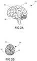
- FIG. 2Ais a lateral view of the brain illustrating the motor cortex, the limbic association area, and the anterior association area.
- FIG. 2Bis a top view of the brain showing the interhemispheric fissure and the two hemispheres of the brain.
- FIG. 3Ais a plan view of an articulated neural electrode assembly in accordance with an embodiment of the invention.
- FIG. 3Bis a cross-sectional view of a panel of an articulated neural electrode assembly according to an embodiment of the invention.
- FIG. 3Cis a partially exploded top isometric view of an articulated neural electrode assembly according to an embodiment of the invention.
- FIG. 3Dis a plan view of an articulated neural electrode assembly according to another embodiment of the invention.
- FIG. 3Eis a plan view of an articulated neural electrode assembly according to another embodiment of the invention.
- FIG. 3Fis a plan view of an articulated neural electrode assembly according to yet another embodiment of the invention.
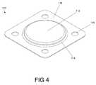
- FIG. 4is a top isometric view of an electrical contact according to an embodiment of the invention.
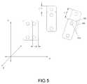
- FIG. 5is a schematic illustration showing exemplary spatially divergent orientations for portions of an articulated neural electrode assembly.
- FIG. 6is an illustration of an articulated neural electrode assembly implanted in a patient.
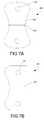
- FIG. 7Ais a plan view of an articulated neural electrode assembly panel according to an embodiment of the invention.
- FIG. 7Bis a plan view of another embodiment of an articulated neural electrode assembly panel.
- FIG. 8is a plan view of another embodiment of an articulated neural electrode assembly panel.
- FIG. 9is a plan view of an articulated neural electrode assembly comprising panels of different dimensions according to an embodiment of the present invention.
- FIG. 10is a plan view of an implantable articulated electrode assembly with panels of different dimensions and electrical contacts of different sizes according to an embodiment of the present invention.
- FIG. 11Ais a schematic illustration of an articulated neural electrode assembly having a leadwire through-hole in a panel in accordance with an embodiment of the invention.
- FIG. 11Bis a partially exploded schematic illustration of the articulated neural electrode assembly of FIG. 11A .
- FIG. 12is a flowchart illustrating an articulated neural electrode implantation, placement, and/or usage procedure according to an embodiment of the invention.
- FIGS. 13A–13Eare flowcharts describing procedures for manufacturing an articulated neural electrode assembly in accordance with various embodiments of the invention.
- apparatuses, devices, and/or systemsmay be configured to apply or deliver neural stimulation to a patient, for example, at one or more cortical and/or other neuroanatomical sites; and associated procedures directed toward the use of such apparatuses, devices, and/or systems.
- one or more portions of apparatuses and/or systems described hereinmay alternatively or additionally be configured to sense or monitor neuroelectric activity within a patient, for example, at one or more cortical and/or other neuroanatomical sites.
- Stimulation systems and/or methods described hereinmay be used to treat a variety of neurological conditions and/or neurologic deficits associated with, for example, stroke, cerebral palsy, multiple sclerosis, movement disorders such as Parkinson's Disease, and/or neuropsychiatric disorders such as depression.
- neural stimulation applied or delivered in accordance with various embodiments of such systems and/or methodsmay alleviate one or more patient symptoms and/or may facilitate or effectuate reorganization of interconnections or synapses between neurons to (a) provide at least some degree of recovery of a lost function; and/or (b) develop one or more compensatory mechanisms to at least partially overcome a functional deficit.
- Such reorganization of neural interconnectionsmay be achieved, at least in part, by a change in the strength of synaptic connections and/or effectuated through a process that corresponds to a mechanism commonly known as Long-Term Potentiation (LTP).
- LTPLong-Term Potentiation
- Electrical stimulation applied to one or more target neural populations either alone or in conjunction with behavioral activities and/or adjunctive or synergistic therapiesmay facilitate or effectuate neural plasticity and the reorganization of synaptic interconnections between neurons.
- FIG. 2Ais a lateral view of the brain 50 illustrating the motor cortex 52 , the limbic association area 54 , and the anterior association area 56 .
- the motor cortex 52is concerned with movements of the face, neck and trunk, arms and legs.
- the motor cortex 52affects motor neurons affecting the skeletal musculature and is essential for the capacity to perform finely graded movements of the arms and legs.
- the anterior association area 56also known as the prefrontal cortex, is concerned with planning movement.
- the limbic association area 54is concerned with emotion and memory storage.
- FIG. 2Bis a top view of the brain 50 showing the interhemispheric fissure 55 and the two hemispheres 58 , 59 of the brain 50 .
- Neural stimulation in association with particular embodiments of the inventionmay involve stimulation of one or more portions of one or more neural areas or regions either sequentially or simultaneously.
- bilateral stimulationmay be desirable wherein electrodes may be placed upon, along, and/or between particular areas of both hemispheres 58 , 59 .
- Such areasmay be neurofunctionally distinct, generally distinct, and/or homotypic.
- Neural sensing or monitoring in association with particular embodiments of the inventionmay involve considerations analogous or similar to those described above.
- the effectiveness of a neural stimulation proceduremay be related to an electric field distribution produced by or associated with an electrode employed in the procedure.
- the electric or stimulation field distributiondepends upon a) electrode design; b) the particular electrical contacts to which electrical stimulation signals are applied; and c) the magnitudes and polarities of applied stimulation signals.
- An electrode's designmay encompass the structure and spatial organization of its contacts, the as-manufactured electrical couplings thereto, and/or other factors.
- electrode placement or positioning proceduresshould facilitate the generation of an intended or desired type of stimulation field distribution.
- Various embodiments of electrode assemblies described hereinmay comprise multiple portions, segments, panels, and/or panels having spatially divergent placement capabilities in relation to one another. Such segments or panels may be placed or positioned in a variety of manners relative to each other and/or one or more neuroanatomical sites or locations, which may facilitate the generation of an intended type of stimulation field distribution.
- FIGS. 3A–6illustrate particular embodiments of articulated neural electrode assemblies 100 (shown as 100 A–E).
- an electrode assembly 100may include an array of electrodes or electrical contacts 110 carried by a support member 120 configured to be implanted and positioned or placed relative to a set of neuroanatomical sites, as further detailed below.
- a neuroanatomical sitemay be a stimulation site and/or a sensing or monitoring site.
- the terms “stimulation site” and/or “monitoring site”refer to an anatomical location where one or more portions of an articulated neural electrode assembly 100 or electrical contacts 110 associated therewith may be placed.
- one or more stimulation and/or monitoring sitesmay be proximate to the cortex, either upon or beneath the dura mater.
- a stimulation sitemay also be a monitoring site.
- FIG. 3Ais a plan view of an articulated neural electrode assembly 100 A according to an embodiment of the invention.
- the electrode assembly 100 Acomprises a set of selectively separable or discontinuous paddles, multi-segmented grids, electrode arrays, and/or panels 105 ; a set of coupling members 140 configured to couple panels 105 in a separable, detachable, severable, and/or removable manner; and a set of electrical leads or lead wires 130 configured to couple the panels 105 to a power source (not shown).
- three panels 105 a–care illustrated, it is to be appreciated that fewer or additional panels 105 may be employed depending upon embodiment details.
- One or more panels 105may be of a contoured shape.
- contouredmay be construed as having one or more rounded or curvaceous corners, edges and/or peripheries.
- a contoured shapemay facilitate panel placement and may increase a manner in which any given panel 105 conforms and/or adheres to a surface of a stimulation site.
- Each panel 105may comprise a support member 120 that carries a set of electrical contacts 110 and possibly a portion of one or more electrical leads 130 coupled to such contacts 110 .
- a support member 120may comprise one or more biologically compatible materials suitable for implantation, for example, a Silicone-based and/or other type of low durometer material. Low durometer materials may provide flexibility and pliability, which may facilitate conformity and/or placement to neural topography at any given stimulation/monitoring site.
- the brainis replete with neuroanatomical irregularities, which may include various irregular, nonuniform, curved, and/or uneven surfaces, shapes, and/or recesses.
- Various embodiments of articulated electrode assemblies 100may facilitate flexible and/or enhanced accuracy positioning and/or improved conformity of one or more panels 105 and/or electrical contacts 110 relative to such irregularities.
- Other neural tissue and/or regionse.g., the spinal cord
- anatomical structurese.g., vertebra within the spinal column
- articulated electrode assemblies 100may aid the selective positioning and/or conformity of one or more panels 105 and/or electrical contacts 110 upon or proximate to targeted neural tissue relative to other anatomical structures.
- one or more panels 105may be dimensioned in a manner that corresponds to a type of neural region and/or structure that such panels 105 may be expected to stimulate and/or monitor.
- a panel 105may be of essentially any shape, in certain embodiments, a panel 105 may have a length ranging between approximately 15 mm 50 mm, and/or a thickness ranging between approximately 0.3 mm 2 mm, and/or a minimum width of approximately 7 mm. In other embodiments, one or more panels 105 may have similar or different dimensions.
- an articulated electrode assembly 100may improve neural stimulation and/or monitoring efficacy, and/or increase a likelihood of realizing an intended neural stimulation and/or monitoring result.
- a support member 120may comprise a single layer of material, or a multiple layer structure or sandwich.
- each panel 105may be formed from an individual support member 120 ; or multiple panels 105 may be formed from a single support member 120 that is shaped or manufactured in accordance with a desired number of panels 105 .
- Each contact 110may comprise a biologically compatible electrically conductive material, for example, stainless steel, Gold, or Platinum-Iridium.
- One or more contacts 110may be coupled to a particular lead wire 130 to facilitate contact biasing at a given potential.
- a signal polarity associated with one or more contacts 110may be specified at one or more stimulation and/or monitoring sites, possibly in a selective manner.
- particular contacts 110may be biased in accordance with a bipolar and/or unipolar polarity scheme, possibly in a time dependent manner. Such biasing flexibility may facilitate or effectuate an intended type of neural stimulation and/or monitoring result.
- a lead wire 130may comprise a coil, and/or another type of wire and/or wire arrangement. Depending upon embodiment details, a lead wire 130 may range in length from approximately 10 cm to 110 cm. In certain embodiments, a lead wire 130 may have a length that falls outside such a range.
- a lead wire 130may be coupled to a contact 110 in a variety of manners, for example, through one or more welds. While two electrical contacts 110 a–b are shown on each panel 105 in FIG. 3A , any given panel 105 may be dimensioned to carry additional or fewer electrical contacts 110 depending upon embodiment details and/or an intended type of neural stimulation and/or neural sensing or monitoring situation under consideration.
- a set of coupling members 140may couple adjacent panels 105 to one another in a separable, detachable, severable, and/or removable manner. In one embodiment, two coupling members 140 span each pair of panels 105 . Other embodiments may rely upon additional or fewer coupling members 140 between each or any given pair of panels 105 , for example, a single coupling member 140 between a first pair of panels 105 , and two or three coupling members between a second pair of panels 105 . One or more coupling members 140 may be removably coupled to a peripheral portion of one or more panels 105 , such as by way of a perforated section 142 .
- a rectilinear stripis illustrated as a coupling member shape, it is to be appreciated that essentially any shape may be employed as long as the coupling members 140 span a set of panels 105 .
- the length of one or more coupling members 140may be established by an expected placement of panels 105 relative to one or more stimulation and/or monitoring sites and/or neural topography associated with such sites. Therefore, an initial distance between one or more panels 105 prior to their separation may vary based on an intended panel placement.
- the electrode assembly 100 A of FIG. 3Ais described and shown with the panels 105 being laterally coupled to one another; however, without departing from the scope of the invention, it is to be appreciated that other embodiments may employ or include other geometric panel orientations. Moreover, the individual dimensions of one or more panels 105 may vary relative to one another. A number of electrical contacts 110 being carried by any given panel 105 may also vary depending on a size and/or shape of the panel 105 and/or a size and/or shape of the contact 110 . In certain embodiments, one or more contacts 110 may have a diameter ranging between approximately 3 7 mm. In other embodiments, one or more contacts 110 may have similar or different diameters or dimensions.
- one or more lead wires 130may couple the electrode assembly 100 to an implantable pulse generator (IPG) 150 .
- IPGimplantable pulse generator
- one or more lead wires 130may couple the electrode assembly 100 to a monitoring device, such as an electroencephalogram (EEG) system (not shown).
- EEGelectroencephalogram
- an IPG 150may itself be capable of both electrical stimulation and EEG monitoring.
- An IPG 150may be surgically implanted within the patient 60 in a subclavicular location.
- the IPG 150may be surgically implanted above the patient's neck, for example, relative to a skull location posterior to the patient's ear and/or proximate to an articulated neural electrode assembly implantation site.
- a surgically formed tunnel or pathmay route the lead wires 130 to the IPG 150 , in a manner understood by those skilled in the art.
- one or more electrically conductive portions of the IPG's housingmay serve as a return electrode for electrical current.
- lead wires 130may couple an electrode assembly 100 to a pulse generator external to the patient 60 .
- An articulated electrode assembly 100may be configured for spatially divergent placement of one or more panels 105 in relation to one another at one or more stimulation and/or monitoring sites.
- a surgeonmay remove, detach, and/or sever particular coupling members 140 to facilitate placement of one or more panels 105 at particular stimulation and/or monitoring sites within the patient 60 .
- a surgeonmay position a first panel 105 a upon or proximate to the patient's motor cortex; a second panel 105 b upon or proximate to the patient's dorsolateral prefrontal cortex; and possibly a third panel 105 c upon or proximate to another neural area or region within the patient 60 .
- Such a panel configurationmay be appropriate, for example, for treating a Parkinson's Disease patient having both motor and cognitive symptoms.
- a surgeonmay position a first set of panels 105 a–b upon or proximate to the patient's motor cortex; and a second set of panels 105 c upon or proximate to the patient's premotor cortex, supplementary motor cortex, somatosensory cortex, or prefrontal cortex.
- the nature of a patient's conditionmay influence or determine an appropriate type of articulated electrode 100 (e.g., one having a particular number of panels 105 and/or particular panel shape(s)) and/or panel placement suitable for the patient.
- FIG. 3Bis a cross sectional view of a panel 105 according to an embodiment of the invention.
- each contact 110may be coupled to a lead wire 130 .
- multiple contactsmay be coupled to a single lead wire 130 .
- each contact 110may be coupled to an electrically distinct lead wire 130 , which may facilitate independent contact biasing.
- independent biasingmay facilitate flexibility in establishing and/or varying potentials within any group of electrical contacts 110 as desired to specifically tailor neural stimulation and/or monitoring in accordance with particular treatment schemes and/or stimulation and/or monitoring sites. This may allow and/or provide for establishment or manipulation of electrical fields with significant flexibility.
- a contact 110may have a recessed side 113 and a protruding or protracted surface or side 112 , which may be defined as a tissue contact or communication side.
- the presence of a protracted side 112may enhance electrical coupling to tissue underlying the contact 110 , thereby possibly reducing or avoiding problems such as unpredictable impedance and/or elevated power consumption.
- a protracted side 112may have a planar surface, as illustrated, or may be angular in orientation relative to a periphery 116 .
- a raised and/or sloping portion 114may form a transition region between the protracted side 112 and the periphery 116 .
- the periphery 116may contain a set of adhesive apertures 115 for facilitating bonding to the support member 120 .
- any surgically suitable bonding materialmay be used to fuse a contact 110 to a support member 120 in an immovable, essentially immovable, or generally immovable manner.
- a lead wire 130may be configured or adapted to couple the recessed underside 113 of the contact 110 to a pulse generator in a manner known to those of skill in the art. However, it should be appreciated by any artisan of ordinary skill in the art that a lead wire 130 may be electrically coupled to essentially any portion of an electrical contact 110 , such as a protracted side 112 and/or a periphery 116 .
- a contact's protracted side 112may have other shapes and forms, and/or a raised portion 114 may be graduated or smoothly sloped.
- an electrical contact 110may take essentially any shape found suitable for neural stimulation and/or monitoring.
- one or more contacts 110may have a tissue communication side that is level or essentially level with or below a surface of a support member 120 .
- Electrical contacts 110 , support members 120 , and/or lead wires 130may be constructed of materials such as those described in U.S. Patent Application Ser. No. 60/482,937, entitled “Apparatuses and Systems for Applying Electrical Stimulation to a Patient,” incorporated herein by reference, and/or other suitable materials.
- FIG. 3Cis a partially exploded top isometric view of an articulated neural electrode assembly 100 B according to another embodiment of the invention.
- a support member 120may be comprised of an upper layer 122 and a lower layer 126 , one or more portions of which may be of identical, essentially identical, or different thickness.
- Each such layer 122 , 126may be formed in accordance with a desired type of as-manufactured panel configuration.
- the upper and lower layers 122 , 126may be bonded together such that a set of electrical contacts 110 and a set of lead wires 130 reside between the upper and lower layers 122 , 126 .
- the upper layer 122may have a plurality of contact apertures 124 which provide openings and/or conductivity conduits for the electrical contacts 110 .
- a suitable bonding agentsuch as a silicone adhesive, for example, can be applied between the two layers 122 , 126 and then cured such that the two layers 122 , 126 fuse into a single structure forming the support member 120 .
- the protracted side 112 of an electrical contact 110may at least partially extend above a contact aperture 124 .
- a series of lead wires 130is shown extending laterally from each of the electrical contacts 110 and similarly from the panels 105 ; however, it is to be noted that the lead wires 130 may also extend longitudinally from one or more electrical contacts 110 and/or panels 105 , for example, in a manner identical or analogous to that shown in FIG. 3A .
- each of the upper and lower layers 122 , 126includes a set of preformed portions or segments 123 , 127 for forming one or more coupling members 140 .
- a coupling member 140may comprise a segment 123 of the lower layer 122 bonded to a corresponding segment 127 of the upper layer 126 , such that the bonded segments 123 , 127 form a coupling member 140 that extends from one panel 105 to another.
- Preformed segments 123 , 127 of the upper and/or lower layers 122 , 126may be thinner than the upper and/or lower layers 123 , 127 themselves to facilitate ease of coupling member removal or detachment.
- a support member 120may comprise one layer (e.g., a lower layer 122 ) that includes a set of preformed portions or segments 123 , 127 ; and a separate counterpart layer (e.g., a separate upper layer 126 ) corresponding to each panel 105 , where each such counterpart layer lacks preformed portions or segments 123 , 127 .
- each individual panel 105may be independently formed from an upper and a lower layer 122 , 126 that lack preformed segments 123 , 127 .
- Coupling members 140may subsequently be formed between particular panels 105 through, for example, a molding and/or bonding procedure.
- FIG. 3Dis a plan view of an articulated neural electrode 100 C according to another embodiment of the invention.
- ease of stimulation and/or monitoring of different neural locationsmay be enhanced through the use of lead wires 130 of different lengths.
- a first lead wire 130 amay be shorter than a second lead wire 130 b and/or a third lead wire 130 a .
- panels 105may be selectively placed or deployed at variable distances with respect to one another. Different lead wire 130 lengths may provide flexibility in positioning electrical contacts 110 relative to stimulation and/or monitoring sites in different neural areas, which may possibly span different brain hemispheres.
- FIG. 3Eis a plan view of an articulated neural electrode assembly 100 D according to another embodiment of the invention.
- one or more peripheral attachment apertures 125may be provided or formed at or near a periphery of the support member 120 .
- medial attachment apertures 145may be provided upon or formed in one or more coupling members 140 .
- Perforations 142may facilitate ease of separation, decoupling, and/or detachment of said panels 105 , and may be located approximately medially between said panels 105 .
- the coupling members 144may be separated centrally, resulting in flap-like portions. A surgeon may thread sutures through some or all of said attachment apertures 125 , 145 to anchor the articulated electrode assembly 100 D to, for example, a patient's dura mater.
- panels 105may be coupled in another manner, such as by a longitudinal strip 146 traversing each of the panels 105 , as shown in FIG. 3F .
- the longitudinal strip 146may be comprised of the same or similar surgically suitable material as a support member 120 .
- the longitudinal strip 146may be adhered and/or bonded to the exterior of either of an upper and/or lower layer 122 , 126 of a support member 120 , or at intersecting portions 148 .
- the longitudinal strip 146may be bonded or partially bonded to an interior portion of one or more panels 105 . Bonding may be accomplished through the use of a silicone adhesive, for example, or any suitable bonding material known in the art.
- FIGS. 13A–13Eare flowcharts describing procedures for manufacturing an articulated neural electrode assembly in accordance with various embodiments of the invention.
- articulated neural electrode assemblies 100may be configured for spatially divergent placement of one or more panels 105 relative to one another at a set of stimulation and/or monitoring sites.
- FIG. 5is an exemplary depiction of a set of panels 105 a–c that are selectively positionable relative to one another along one or more of x, y, and z axes or directions and/or planes corresponding thereto.
- coupling members(not shown) may be removed, detached, or separated by a surgeon to facilitate panel placement relative to a set of stimulation sites.
- an articulated electrode assembly 100may be capable of signal transfer, exchange, or communication using an array of electrical contacts 110 that may be arranged or positioned in a multitude of possible orientations.
- minor displacements in one or more directions or planesmay be desired. For example, if it is found or expected that neural stimulation efficacy is improved by displacing or repositioning a first panel 105 a along an x axis from a first position (shown in phantom) to a second position, the change depicted by ⁇ x, then such a displacement may be made. Likewise, placement of a second panel 105 b may involve a shift along a y-axis from a first position (shown in phantom) to a second position, the change indicated by ⁇ y. Similarly, a third panel 105 c may be shifted from an initial position (phantom) to another position resulting in a ⁇ z.
- an articulated electrode assembly 100can be placed in a multitude of desirable configurations upon or proximate to the brain and/or other neural tissue (e.g., the spinal cord). Configurable placement of one or more panels 105 may facilitate the generation of an intended or desirable electric field distribution. Although shown as implanted in one hemisphere, it is to be appreciated that a single articulated electrode 100 may have panels 105 implanted in both hemispheres. The spatially divergent structure of an articulated electrode assembly 100 may therefore facilitate various bilateral stimulation and/or monitoring capabilities. In such situations, multiple surgical openings may facilitate panel 105 implantation such that lead wires 130 are prevented from crossing or traversing particular anatomical structures, e.g., the interhemispheric fissure 55 .
- FIGS. 7A , 7 B and 8illustrate examples of different shapes of panels 205 , 305 and 405 , respectively, according to particular embodiments of the invention. Although shown in a single form, it is to be understood that particular panels 205 , 305 , 405 may be coupled to adjacent or nearby panels 205 , 305 , 405 by one or more coupling members (not shown).
- a panel 205has exemplary dimensions wherein a support member 220 may have a long or maximum length axis and at least one shortened, narrow, reduced, or minimum length axis. The presence of a shortened axis may form a waist portion 222 .
- a panel 305may have an asymmetric waist portion 322 .
- FIG. 7Aillustrates a panel 205 having a single waist portion 222
- a panel 405may be configured, as illustrated in FIG. 8 , as having multiple waist portions 422 .
- a panel 405may include multiple contacts 410 coupled to a single lead wire 130 .
- one or more contacts 410may be coupled to electrically distinct lead wires 130 .
- a waist portion 422may serve as a type of coupling member that facilitates separation and configurable placement of individual contacts 410 or contact sets associated with the panel 405 .
- FIG. 9is a plan view of an articulated neural electrode assembly 500 comprising panels 105 , 205 , 305 of different shapes, in accordance with another embodiment of the invention.
- An articulated electrode assembly 500 of the type shown in FIG. 9may comprise one or more of a generally rectilinearly shaped panel 105 , a spherically shaped panel 205 , a plano-concave shaped panel 305 , and/or one or more otherwise shaped panels.
- FIG. 10is a plan view of an articulated neural electrode assembly 600 according to another embodiment of the invention.
- particular panels 605 , 606may be of different shapes and/or sizes, and/or one or more panels 605 , 606 may carry a different number of and/or differently dimensioned electrical contacts 610 a , 610 b .
- one contact 610 amay be of a smaller diameter or area than another contact 610 b .
- the use of panels 605 , 606 that carry different numbers of electrical contacts 610 a , 610 b and/or differently dimensioned contacts 610 a , 610 bmay aid panel placement procedures and/or impact neural stimulation and/or monitoring efficiency.
- a larger-area contact 610 bmay facilitate more efficient delivery of larger magnitude stimulation signals that a smaller-area contact 610 a .
- U.S. patent application Ser. No. 10/112,301, filed Mar. 28, 2002 entitled “Electrode Geometries for Efficient Neural Stimulation,”provides a further discussion of the relationship between contact shape and electrical parameters, and is incorporated herein by reference. Altering contact dimension, panel dimension, and/or panel placement may optimize signal transfer, exchange, and/or communication into and/or through various neural structures and/or layers (e.g., cortical layers) associated with a stimulation and/or monitoring site.
- FIG. 11Ais a plan view and FIG. 11B is a partially exploded perspective view of an articulated neural electrode assembly 700 according to another embodiment of the invention.
- a plurality of panels 705need not be laterally placed relative to one another.
- One or more panels 705may be placed in another orientation, for example, perpendicularly, relative to at least one other panel 705 .
- portions of one or more lead wires 730may be slidably carried within a support member 720 .
- a support member 720may include a lead through-hole 735 formed therein.
- upper and lower support member layers 722 and 726respectively, may each have matingly opposed grooves 723 and 727 therein that facilitate through-hole formation.
- FIG. 12is a flowchart illustrating an articulated neural electrode implantation, placement, and/or usage procedure 1000 according to an embodiment of the invention. Depending upon embodiment details, the description that follows may apply to essentially any articulated neural electrode embodiment in accordance with the invention, including one or more embodiments described above with reference to FIGS. 3A through 11B .
- the procedure 1000comprises a site determination procedure 1010 that may involve identifying or determining a set of stimulation and/or monitoring sites at which one or more portions of an articulated neural electrode 100 may be implanted.
- a site determination procedure 1010may involve (1) identification of one or more anatomical landmarks; (2) preoperatively (for example, using Transcranial Magnetic Stimulation) and/or intraoperatively stimulating one or more neural locations to identify or map particular neural regions that induce or evoke a given type of patient response (for example, a movement or a sensation); (3) estimating a location at which the brain may recruit neurons to carry out a given type of neural activity that was previously performed by a damaged portion of the brain; (4) a neural imaging procedure; and/or (5) statistical considerations based upon one or more patient population samples.
- a site determination procedure 1010may additionally or alternatively involve the use of a neuronavigation system.
- a neuronavigation systemmay comprise stereotactic surgical equipment that may be used to determine the precise relationship between surgical instruments and anatomical structures, in a manner understood by those skilled in the art.
- An articulated neural electrode implantation, placement, and/or usage procedure 1000may additionally include an access procedure 1020 that involves accessing one or more stimulation and/or monitoring sites.
- An accessing procedure 1020may rely upon surgical techniques, for example, performing a craniotomy and/or forming one or more burr holes in the patient's skull.
- the procedure 1000may further include a separation procedure 1030 that involves separating, detaching, decopuling, and/or removing coupling members 140 that couple an articulated electrode's panels 105 , possibly in a selective manner. Once separated, panels 105 may be available for spatially divergent placement relative to one another and/or a set of stimulation and/or monitoring sites.
- a separation procedure 1030that involves separating, detaching, decopuling, and/or removing coupling members 140 that couple an articulated electrode's panels 105 , possibly in a selective manner. Once separated, panels 105 may be available for spatially divergent placement relative to one another and/or a set of stimulation and/or monitoring sites.
- An articulated electrode implantation, placement, and/or usage procedure 1000may also include a placement procedure 1040 .
- a placement procedure 1040involves a general placement or positioning of one or more panels 105 at particular stimulation and/or monitoring sites.
- a placement procedure 1040may alternatively or additionally involve specific placement, positional adjustment, and/or positional readjustment of one or more panels 105 relative to given stimulation and/or monitoring sites.
- a more specific placementmay involve fine adjustments in one or more of an x, y, and/or z direction and/or planes corresponding thereto.
- a specific placementmay involve maneuvering a panel 105 such that electrical contacts 110 carried thereby are positioned in a desired manner relative to a stimulation and/or monitoring site, possibly based upon neural topography.
- a procedure 1000may further include an anchoring procedure 1060 that involves securing particular portions of one or more panels 105 to a stimulation and/or monitoring site, for example, through the use of sutures.
- a procedure 1000may additionally include a lead wire placement procedure 1070 , which may involve routing lead wires 130 in and/or around tissues between an articulated electrode assembly 100 and a pulse generator 150 .
- a lead wire placement procedure 1070may involve a surgical tunneling procedure that facilitates routing lead wires 130 between a subclavicular region, along the back of the neck, and around a portion of a patient's skull 57 ( FIG. 6 ).
- An articulated neural electrode implantation, placement, and/or usage procedure 1000may also include a stimulation procedure 1080 and/or a monitoring procedure 1082 .
- a stimulation procedure 1080electrical energy may be supplied to one or more panels 105 or electrical contacts 110 of an articulated electrode assembly 100 to provide, apply, or deliver electrical energy at or proximate to one or more stimulation sites.
- electrical energymay be applied to panels 105 in a simultaneous, sequential, or pseudo-random manner.
- a monitoring procedure 1082one or more panels 105 or electrical contacts 110 may be used to detect neuroelectric activity at or proximate to one or more monitoring sites.
Landscapes
- Health & Medical Sciences (AREA)
- Neurology (AREA)
- Neurosurgery (AREA)
- Psychology (AREA)
- Cardiology (AREA)
- Heart & Thoracic Surgery (AREA)
- Engineering & Computer Science (AREA)
- Biomedical Technology (AREA)
- Nuclear Medicine, Radiotherapy & Molecular Imaging (AREA)
- Radiology & Medical Imaging (AREA)
- Life Sciences & Earth Sciences (AREA)
- Animal Behavior & Ethology (AREA)
- General Health & Medical Sciences (AREA)
- Public Health (AREA)
- Veterinary Medicine (AREA)
- Orthopedic Medicine & Surgery (AREA)
- Electrotherapy Devices (AREA)
Abstract
Description
Claims (26)
Priority Applications (2)
| Application Number | Priority Date | Filing Date | Title |
|---|---|---|---|
| US10/707,818US7107097B2 (en) | 2004-01-14 | 2004-01-14 | Articulated neural electrode assembly |
| PCT/US2005/001672WO2005068012A1 (en) | 2004-01-14 | 2005-01-14 | Articulated neural electrode assembly |
Applications Claiming Priority (1)
| Application Number | Priority Date | Filing Date | Title |
|---|---|---|---|
| US10/707,818US7107097B2 (en) | 2004-01-14 | 2004-01-14 | Articulated neural electrode assembly |
Publications (2)
| Publication Number | Publication Date |
|---|---|
| US20050154435A1 US20050154435A1 (en) | 2005-07-14 |
| US7107097B2true US7107097B2 (en) | 2006-09-12 |
Family
ID=34738991
Family Applications (1)
| Application Number | Title | Priority Date | Filing Date |
|---|---|---|---|
| US10/707,818Expired - Fee RelatedUS7107097B2 (en) | 2004-01-14 | 2004-01-14 | Articulated neural electrode assembly |
Country Status (2)
| Country | Link |
|---|---|
| US (1) | US7107097B2 (en) |
| WO (1) | WO2005068012A1 (en) |
Cited By (78)
| Publication number | Priority date | Publication date | Assignee | Title |
|---|---|---|---|---|
| US20040073270A1 (en)* | 2000-07-13 | 2004-04-15 | Firlik Andrew D. | Methods and apparatus for effectuating a lasting change in a neural-function of a patient |
| US20050070982A1 (en)* | 2003-09-30 | 2005-03-31 | Heruth Kenneth T. | Field steerable electrical stimulation paddle, lead system, and medical device incorporating the same |
| US20050113882A1 (en)* | 2003-11-20 | 2005-05-26 | Advanced Neuromodulation Systems, Inc. | Electrical stimulation system, lead, and method providing reduced neuroplasticity effects |
| US20060069415A1 (en)* | 2003-11-20 | 2006-03-30 | Advanced Neuromodulation Systems, Inc. | Electrical stimulation system, lead, and method providing modified reduced neuroplasticity effect |
| US20060161219A1 (en)* | 2003-11-20 | 2006-07-20 | Advanced Neuromodulation Systems, Inc. | Electrical stimulation system and method for stimulating multiple locations of target nerve tissue in the brain to treat multiple conditions in the body |
| US20060161216A1 (en)* | 2004-10-18 | 2006-07-20 | John Constance M | Device for neuromuscular peripheral body stimulation and electrical stimulation (ES) for wound healing using RF energy harvesting |
| US20060184220A1 (en)* | 2003-05-16 | 2006-08-17 | Medtronic, Inc. | Explantation of implantable medical device |
| US20060184209A1 (en)* | 2004-09-02 | 2006-08-17 | John Constance M | Device for brain stimulation using RF energy harvesting |
| US20060253169A1 (en)* | 2004-11-12 | 2006-11-09 | Northstar Neuroscience, Inc. | Systems and methods for selecting stimulation sites and applying treatment, including treatment of symptoms of Parkinson's disease, other movement disorders, and/or drug side effects |
| US20060264729A1 (en)* | 2005-05-19 | 2006-11-23 | Putz David A | Cortical sensing device with pads |
| US20070010862A1 (en)* | 2005-04-26 | 2007-01-11 | Thomas Osypka | Apparatus and method for providing an electrical field to a targeted area |
| USD541421S1 (en)* | 2004-07-13 | 2007-04-24 | Everest Biomedical Instruments Co. | Electrode array |
| US20070100398A1 (en)* | 2005-10-19 | 2007-05-03 | Northstar Neuroscience, Inc. | Neural stimulation system and optical monitoring systems and methods |
| US20070112402A1 (en)* | 2005-10-19 | 2007-05-17 | Duke University | Electrode systems and related methods for providing therapeutic differential tissue stimulation |
| US20070265691A1 (en)* | 2006-04-28 | 2007-11-15 | John Swanson | Spinal cord stimulation paddle lead and method of making the same |
| US7299096B2 (en) | 2001-03-08 | 2007-11-20 | Northstar Neuroscience, Inc. | System and method for treating Parkinson's Disease and other movement disorders |
| US7305268B2 (en) | 2000-07-13 | 2007-12-04 | Northstar Neurscience, Inc. | Systems and methods for automatically optimizing stimulus parameters and electrode configurations for neuro-stimulators |
| US20080004676A1 (en)* | 2006-06-16 | 2008-01-03 | Osypka Thomas P | Implantable neurostimulation systems |
| US20080058876A1 (en)* | 2006-09-06 | 2008-03-06 | Giancarlo Barolat | Implantable reel for coiling an implantable elongated member |
| US7353064B2 (en) | 2002-12-10 | 2008-04-01 | Northstar Neuroscience, Inc. | Systems and methods for enhancing or optimizing neural stimulation therapy for treating symptoms of movement disorders and/or other neurologic dysfunction |
| US20080154331A1 (en)* | 2006-12-21 | 2008-06-26 | Varghese John | Device for multicentric brain modulation, repair and interface |
| US20080183224A1 (en)* | 2007-01-25 | 2008-07-31 | Giancarlo Barolat | Electrode paddle for neurostimulation |
| US7483747B2 (en) | 2004-07-15 | 2009-01-27 | Northstar Neuroscience, Inc. | Systems and methods for enhancing or affecting neural stimulation efficiency and/or efficacy |
| US7529586B2 (en) | 2002-12-09 | 2009-05-05 | Medtronic, Inc. | Concavity of an implantable medical device |
| US20090118804A1 (en)* | 2007-11-05 | 2009-05-07 | Advanced Bionics Corporation | Method of mounting minimally invasive plug electrodes within cranium of patient |
| US20090118787A1 (en)* | 2007-11-02 | 2009-05-07 | Advanced Bionics Corporation | Closed-loop feedback for steering stimulation energy within tissue |
| US20090149898A1 (en)* | 2007-12-07 | 2009-06-11 | Northstar Neuroscience, Inc. | Systems and Methods for Providing Targeted Neural Stimulation Therapy to Address Neurological Disorders, Including Neuropyschiatric and Neuropyschological Disorders |
| US7565199B2 (en) | 2002-12-09 | 2009-07-21 | Advanced Neuromodulation Systems, Inc. | Methods for treating and/or collecting information regarding neurological disorders, including language disorders |
| US7577481B2 (en) | 2000-07-13 | 2009-08-18 | Advanced Neuromodulation Systems, Inc. | Methods and apparatus for effectuating a lasting change in a neural-function of a patient |
| US7596399B2 (en)* | 2004-04-29 | 2009-09-29 | Medtronic, Inc | Implantation of implantable medical device |
| US7596408B2 (en) | 2002-12-09 | 2009-09-29 | Medtronic, Inc. | Implantable medical device with anti-infection agent |
| US20090276021A1 (en)* | 2008-04-30 | 2009-11-05 | Boston Scientific Neuromodulation Corporation | Electrodes for stimulation leads and methods of manufacture and use |
| US20090299444A1 (en)* | 2008-05-29 | 2009-12-03 | Nevro Corporation | Percutaneous Leads with Laterally Displaceable Portions, and Associated Systems and Methods |
| US20100036469A1 (en)* | 2006-02-10 | 2010-02-11 | Swanson John W | Self-Folding Paddle Lead and Method of Fabricating a Paddle Lead |
| US7684866B2 (en) | 2003-08-01 | 2010-03-23 | Advanced Neuromodulation Systems, Inc. | Apparatus and methods for applying neural stimulation to a patient |
| US20100094387A1 (en)* | 2008-10-09 | 2010-04-15 | Boston Scientific Neuromodulation Corporation | Electrode design for leads of implantable electric stimulation systems and methods of making and using |
| US7756584B2 (en) | 2000-07-13 | 2010-07-13 | Advanced Neuromodulation Systems, Inc. | Methods and apparatus for effectuating a lasting change in a neural-function of a patient |
| US20100204754A1 (en)* | 2009-02-09 | 2010-08-12 | Rainbow Medical Ltd. | Retinal prosthesis |
| US7831305B2 (en) | 2001-10-15 | 2010-11-09 | Advanced Neuromodulation Systems, Inc. | Neural stimulation system and method responsive to collateral neural activity |
| US7881796B2 (en) | 2003-05-16 | 2011-02-01 | Medtronic, Inc. | Implantable medical device with a nonhermetic battery |
| US7974707B2 (en) | 2007-01-26 | 2011-07-05 | Cyberonics, Inc. | Electrode assembly with fibers for a medical device |
| US20110237921A1 (en)* | 2009-09-23 | 2011-09-29 | Ripple Llc | Systems and methods for flexible electrodes |
| US8126568B2 (en) | 2002-03-28 | 2012-02-28 | Advanced Neuromodulation Systems, Inc. | Electrode geometries for efficient neural stimulation |
| US8180462B2 (en) | 2006-04-18 | 2012-05-15 | Cyberonics, Inc. | Heat dissipation for a lead assembly |
| US8214057B2 (en) | 2007-10-16 | 2012-07-03 | Giancarlo Barolat | Surgically implantable electrodes |
| US8428740B2 (en) | 2010-08-06 | 2013-04-23 | Nano-Retina, Inc. | Retinal prosthesis techniques |
| US8442641B2 (en) | 2010-08-06 | 2013-05-14 | Nano-Retina, Inc. | Retinal prosthesis techniques |
| US8478420B2 (en) | 2006-07-12 | 2013-07-02 | Cyberonics, Inc. | Implantable medical device charge balance assessment |
| US8478428B2 (en) | 2010-04-23 | 2013-07-02 | Cyberonics, Inc. | Helical electrode for nerve stimulation |
| US8483846B2 (en) | 2006-07-26 | 2013-07-09 | Cyberonics, Inc. | Multi-electrode assembly for an implantable medical device |
| US8549015B2 (en) | 2007-05-01 | 2013-10-01 | Giancarlo Barolat | Method and system for distinguishing nociceptive pain from neuropathic pain |
| US8571669B2 (en) | 2011-02-24 | 2013-10-29 | Nano-Retina, Inc. | Retinal prosthesis with efficient processing circuits |
| US8706243B2 (en) | 2009-02-09 | 2014-04-22 | Rainbow Medical Ltd. | Retinal prosthesis techniques |
| US8718777B2 (en) | 2002-11-27 | 2014-05-06 | Advanced Neuromodulation Systems, Inc. | Methods and systems for intracranial neurostimulation and/or sensing |
| US8718784B2 (en) | 2010-01-14 | 2014-05-06 | Nano-Retina, Inc. | Penetrating electrodes for retinal stimulation |
| US8738126B2 (en) | 2006-03-29 | 2014-05-27 | Catholic Healthcare West | Synchronization of vagus nerve stimulation with the cardiac cycle of a patient |
| US8805519B2 (en) | 2010-09-30 | 2014-08-12 | Nevro Corporation | Systems and methods for detecting intrathecal penetration |
| US8868203B2 (en) | 2007-10-26 | 2014-10-21 | Cyberonics, Inc. | Dynamic lead condition detection for an implantable medical device |
| US8929991B2 (en) | 2005-10-19 | 2015-01-06 | Advanced Neuromodulation Systems, Inc. | Methods for establishing parameters for neural stimulation, including via performance of working memory tasks, and associated kits |
| US8942798B2 (en) | 2007-10-26 | 2015-01-27 | Cyberonics, Inc. | Alternative operation mode for an implantable medical device based upon lead condition |
| US8954165B2 (en) | 2012-01-25 | 2015-02-10 | Nevro Corporation | Lead anchors and associated systems and methods |
| US9084901B2 (en) | 2006-04-28 | 2015-07-21 | Medtronic, Inc. | Cranial implant |
| US9162072B2 (en) | 2004-04-30 | 2015-10-20 | Medtronic, Inc. | Implantable medical device with lubricious material |
| US9265935B2 (en) | 2013-06-28 | 2016-02-23 | Nevro Corporation | Neurological stimulation lead anchors and associated systems and methods |
| US9331791B2 (en) | 2014-01-21 | 2016-05-03 | Nano Retina Ltd. | Transfer of power and data |
| US9370417B2 (en) | 2013-03-14 | 2016-06-21 | Nano-Retina, Inc. | Foveated retinal prosthesis |
| US9393432B2 (en) | 2008-10-31 | 2016-07-19 | Medtronic, Inc. | Non-hermetic direct current interconnect |
| US9474902B2 (en) | 2013-12-31 | 2016-10-25 | Nano Retina Ltd. | Wearable apparatus for delivery of power to a retinal prosthesis |
| US20170360505A1 (en)* | 2016-06-17 | 2017-12-21 | Megadyne Medical Products, Inc. | Electrosurgical return electrode and rfid system |
| USD872279S1 (en)* | 2017-12-22 | 2020-01-07 | CB Innovations, LLC | Emergency cardiac and electrocardiogram electrode placement system |
| US10729564B2 (en) | 2018-01-12 | 2020-08-04 | Ripple Llc | Sensor system |
| US10980999B2 (en) | 2017-03-09 | 2021-04-20 | Nevro Corp. | Paddle leads and delivery tools, and associated systems and methods |
| US11420045B2 (en) | 2018-03-29 | 2022-08-23 | Nevro Corp. | Leads having sidewall openings, and associated systems and methods |
| US11602630B2 (en) | 2017-06-07 | 2023-03-14 | Neuronexus Technologies, Inc. | Systems and methods for flexible electrode arrays |
| US12318314B2 (en) | 2022-06-03 | 2025-06-03 | JSG IP Ventures, LLC | System and methods for residual limbs of amputees |
| US12324754B1 (en) | 2024-08-20 | 2025-06-10 | JSG IP Ventures, LLC | System for residual limbs of amputees |
| US12329969B1 (en) | 2024-08-20 | 2025-06-17 | JSG IP Ventures, LLC | System and methods for residual limbs of amputees |
| US12337177B1 (en) | 2024-08-20 | 2025-06-24 | JSG IP Ventures, LLC | Method for residual limbs of amputees |
Families Citing this family (46)
| Publication number | Priority date | Publication date | Assignee | Title |
|---|---|---|---|---|
| WO2005107854A2 (en) | 2004-05-04 | 2005-11-17 | The Cleveland Clinic Foundation | Corpus callosum neuromodulation assembly |
| US8515541B1 (en) | 2004-12-22 | 2013-08-20 | Boston Scientific Neuromodulation Corporation | Methods and systems for treating post-stroke disorders |
| US9314633B2 (en) | 2008-01-25 | 2016-04-19 | Cyberonics, Inc. | Contingent cardio-protection for epilepsy patients |
| US8565867B2 (en) | 2005-01-28 | 2013-10-22 | Cyberonics, Inc. | Changeable electrode polarity stimulation by an implantable medical device |
| US8260426B2 (en) | 2008-01-25 | 2012-09-04 | Cyberonics, Inc. | Method, apparatus and system for bipolar charge utilization during stimulation by an implantable medical device |
| US20070073354A1 (en) | 2005-09-26 | 2007-03-29 | Knudson Mark B | Neural blocking therapy |
| US7996079B2 (en) | 2006-01-24 | 2011-08-09 | Cyberonics, Inc. | Input response override for an implantable medical device |
| US7962220B2 (en) | 2006-04-28 | 2011-06-14 | Cyberonics, Inc. | Compensation reduction in tissue stimulation therapy |
| US7869885B2 (en) | 2006-04-28 | 2011-01-11 | Cyberonics, Inc | Threshold optimization for tissue stimulation therapy |
| US8401654B1 (en)* | 2006-06-30 | 2013-03-19 | Boston Scientific Neuromodulation Corporation | Methods and systems for treating one or more effects of deafferentation |
| US7869867B2 (en) | 2006-10-27 | 2011-01-11 | Cyberonics, Inc. | Implantable neurostimulator with refractory stimulation |
| US8290599B2 (en) | 2006-12-12 | 2012-10-16 | Boston Scientific Neuromodulation Corporation | Electrode arrangements for tissue stimulation and methods of use and manufacture |
| US7974701B2 (en) | 2007-04-27 | 2011-07-05 | Cyberonics, Inc. | Dosing limitation for an implantable medical device |
| US20090105786A1 (en)* | 2007-10-22 | 2009-04-23 | University Of Washington | Method and device for strengthening synaptic connections |
| JP4488057B2 (en)* | 2007-11-09 | 2010-06-23 | セイコーエプソン株式会社 | Active matrix device, electro-optical display device, and electronic apparatus |
| US8204603B2 (en) | 2008-04-25 | 2012-06-19 | Cyberonics, Inc. | Blocking exogenous action potentials by an implantable medical device |
| WO2009143177A2 (en)* | 2008-05-19 | 2009-11-26 | Nevro Corporation | Implantable neural stimulation electrode assemblies and methods for stimulating spinal neural sites |
| US8457747B2 (en) | 2008-10-20 | 2013-06-04 | Cyberonics, Inc. | Neurostimulation with signal duration determined by a cardiac cycle |
| US8255057B2 (en) | 2009-01-29 | 2012-08-28 | Nevro Corporation | Systems and methods for producing asynchronous neural responses to treat pain and/or other patient conditions |
| US9327121B2 (en) | 2011-09-08 | 2016-05-03 | Nevro Corporation | Selective high frequency spinal cord modulation for inhibiting pain, including cephalic and/or total body pain with reduced side effects, and associated systems and methods |
| US8874235B1 (en) | 2008-12-12 | 2014-10-28 | Greatbatch Ltd. | Self fixing spinal cord stimulation paddle lead |
| KR101088806B1 (en)* | 2009-01-07 | 2011-12-01 | 주식회사 뉴로바이오시스 | Microelectrode array package using liquid crystal polymer and manufacturing method thereof |
| US20100191304A1 (en) | 2009-01-23 | 2010-07-29 | Scott Timothy L | Implantable Medical Device for Providing Chronic Condition Therapy and Acute Condition Therapy Using Vagus Nerve Stimulation |
| US8244374B1 (en) | 2009-03-23 | 2012-08-14 | Advanced NeuromodulationSystems, Inc. | Implantable paddle lead comprising stretching electrical traces and method of fabrication |
| US8271099B1 (en) | 2009-03-23 | 2012-09-18 | Advanced Neuromodulation Systems, Inc. | Implantable paddle lead comprising compressive longitudinal members for supporting electrodes and method of fabrication |
| ES2942684T3 (en) | 2009-04-22 | 2023-06-05 | Nevro Corp | Spinal cord modulation systems to induce paresthetic and anesthetic effects |
| EP3228350B1 (en) | 2009-04-22 | 2025-09-24 | Nevro Corporation | Device for selective high frequency spinal cord modulation for inhibiting pain with reduced side effects, and associated systems and methods |
| US8498710B2 (en) | 2009-07-28 | 2013-07-30 | Nevro Corporation | Linked area parameter adjustment for spinal cord stimulation and associated systems and methods |
| WO2012075198A2 (en) | 2010-11-30 | 2012-06-07 | Nevro Corporation | Extended pain relief via high frequency spinal cord modulation, and associated systems and methods |
| DE102011101580B4 (en)* | 2011-05-13 | 2015-03-12 | Dräger Medical GmbH | Sensor device for the electromyographic derivation of muscle signals as well as methods for the preparation of an electromyographic derivation of muscle signals and system |
| EP2736587B1 (en)* | 2011-07-25 | 2018-10-03 | NeuroNexus Technologies, Inc. | Neural device with modular electrode array |
| EP2792322B1 (en)* | 2011-08-25 | 2017-10-04 | Covidien LP | Systems and devices for treatment of luminal tissue |
| US9833614B1 (en) | 2012-06-22 | 2017-12-05 | Nevro Corp. | Autonomic nervous system control via high frequency spinal cord modulation, and associated systems and methods |
| US8818483B2 (en)* | 2012-12-20 | 2014-08-26 | Boston Scientific Neuromodulation Corporation | Methods of making a paddle lead with a carrier and leads and systems formed thereby |
| US9486641B2 (en)* | 2013-03-16 | 2016-11-08 | Lawrence Livermore National Security, Llc | Incorporating an optical waveguide into a neural interface |
| US9895539B1 (en) | 2013-06-10 | 2018-02-20 | Nevro Corp. | Methods and systems for disease treatment using electrical stimulation |
| CO7060219A1 (en)* | 2013-09-13 | 2014-09-19 | Tapiero Juan Espitia | Brain electronic stimulation giver |
| US10149978B1 (en) | 2013-11-07 | 2018-12-11 | Nevro Corp. | Spinal cord modulation for inhibiting pain via short pulse width waveforms, and associated systems and methods |
| US11318310B1 (en) | 2015-10-26 | 2022-05-03 | Nevro Corp. | Neuromodulation for altering autonomic functions, and associated systems and methods |
| CN109310865B (en) | 2016-01-25 | 2022-09-13 | 内弗洛公司 | Electrostimulation treatment of congestive heart failure, and associated systems and methods |
| US11590352B2 (en) | 2019-01-29 | 2023-02-28 | Nevro Corp. | Ramped therapeutic signals for modulating inhibitory interneurons, and associated systems and methods |
| US20220273220A1 (en) | 2019-07-15 | 2022-09-01 | Institut National De La Sante Et De La Recherche Medicale(Inserm) | Implant, ensemble comprising such an implant and method for fabricating such an implant |
| EP4037756B1 (en)* | 2019-10-02 | 2025-07-30 | BIOTRONIK SE & Co. KG | Medical electrode device for implantation into a patient |
| US20240181256A1 (en)* | 2021-06-18 | 2024-06-06 | Cochlear Limited | Vagal nerve stimulation |
| EP4486432A1 (en)* | 2022-03-01 | 2025-01-08 | BIOTRONIK SE & Co. KG | Medical electrode device comprising at least one contact element and method for fabricating same |
| CN119423766B (en)* | 2025-01-08 | 2025-07-01 | 光子集成(温州)创新研究院 | A FPC flexible electrode |
Citations (14)
| Publication number | Priority date | Publication date | Assignee | Title |
|---|---|---|---|---|
| US4102331A (en)* | 1976-09-21 | 1978-07-25 | Datascope Corporation | Device for transmitting electrical energy |
| US4233987A (en)* | 1978-08-18 | 1980-11-18 | Alfred Feingold | Curvilinear electrocardiograph electrode strip |
| US4522211A (en)* | 1979-12-06 | 1985-06-11 | C. R. Bard, Inc. | Medical electrode construction |
| US4903702A (en)* | 1988-10-17 | 1990-02-27 | Ad-Tech Medical Instrument Corporation | Brain-contact for sensing epileptogenic foci with improved accuracy |
| US5133356A (en)* | 1991-04-16 | 1992-07-28 | Minnesota Mining And Manufacturing Company | Biomedical electrode having centrally-positioned tab construction |
| US5215087A (en)* | 1988-09-22 | 1993-06-01 | Minnesota Mining And Manufacturing Company | Biomedical electrode construction |
| US5445537A (en)* | 1994-10-31 | 1995-08-29 | Src Associates, Inc. | Strain relief coupling assembly for an electrode |
| US5772591A (en) | 1995-06-06 | 1998-06-30 | Patient Comfort, Inc. | Electrode assembly for signaling a monitor |
| US5846217A (en)* | 1997-07-29 | 1998-12-08 | Iomed, Inc. | Iontophoretic bioelectrode and method of using same |
| US6301493B1 (en) | 1999-07-10 | 2001-10-09 | Physiometrix, Inc. | Reservoir electrodes for electroencephalograph headgear appliance |
| US20020128700A1 (en)* | 2001-03-08 | 2002-09-12 | Cross Thomas E. | Lead with adjustable angular and spatial relationships between electrodes |
| US20040093051A1 (en) | 2000-05-05 | 2004-05-13 | Chinn Kenny K. | Method of making a pin with multiple in-line contacts |
| US6782293B2 (en)* | 2001-09-14 | 2004-08-24 | Zoll Medical Corporation | Defibrillation electrode assembly including CPR pad |
| US20040243205A1 (en) | 2003-05-30 | 2004-12-02 | Medtronic, Inc. | Implantable cortical neural lead and method |
- 2004
- 2004-01-14USUS10/707,818patent/US7107097B2/ennot_activeExpired - Fee Related
- 2005
- 2005-01-14WOPCT/US2005/001672patent/WO2005068012A1/enactiveApplication Filing
Patent Citations (14)
| Publication number | Priority date | Publication date | Assignee | Title |
|---|---|---|---|---|
| US4102331A (en)* | 1976-09-21 | 1978-07-25 | Datascope Corporation | Device for transmitting electrical energy |
| US4233987A (en)* | 1978-08-18 | 1980-11-18 | Alfred Feingold | Curvilinear electrocardiograph electrode strip |
| US4522211A (en)* | 1979-12-06 | 1985-06-11 | C. R. Bard, Inc. | Medical electrode construction |
| US5215087A (en)* | 1988-09-22 | 1993-06-01 | Minnesota Mining And Manufacturing Company | Biomedical electrode construction |
| US4903702A (en)* | 1988-10-17 | 1990-02-27 | Ad-Tech Medical Instrument Corporation | Brain-contact for sensing epileptogenic foci with improved accuracy |
| US5133356A (en)* | 1991-04-16 | 1992-07-28 | Minnesota Mining And Manufacturing Company | Biomedical electrode having centrally-positioned tab construction |
| US5445537A (en)* | 1994-10-31 | 1995-08-29 | Src Associates, Inc. | Strain relief coupling assembly for an electrode |
| US5772591A (en) | 1995-06-06 | 1998-06-30 | Patient Comfort, Inc. | Electrode assembly for signaling a monitor |
| US5846217A (en)* | 1997-07-29 | 1998-12-08 | Iomed, Inc. | Iontophoretic bioelectrode and method of using same |
| US6301493B1 (en) | 1999-07-10 | 2001-10-09 | Physiometrix, Inc. | Reservoir electrodes for electroencephalograph headgear appliance |
| US20040093051A1 (en) | 2000-05-05 | 2004-05-13 | Chinn Kenny K. | Method of making a pin with multiple in-line contacts |
| US20020128700A1 (en)* | 2001-03-08 | 2002-09-12 | Cross Thomas E. | Lead with adjustable angular and spatial relationships between electrodes |
| US6782293B2 (en)* | 2001-09-14 | 2004-08-24 | Zoll Medical Corporation | Defibrillation electrode assembly including CPR pad |
| US20040243205A1 (en) | 2003-05-30 | 2004-12-02 | Medtronic, Inc. | Implantable cortical neural lead and method |
Cited By (139)
| Publication number | Priority date | Publication date | Assignee | Title |
|---|---|---|---|---|
| US7577481B2 (en) | 2000-07-13 | 2009-08-18 | Advanced Neuromodulation Systems, Inc. | Methods and apparatus for effectuating a lasting change in a neural-function of a patient |
| US8195300B2 (en) | 2000-07-13 | 2012-06-05 | Advanced Neuromodulation Systems, Inc. | Systems and methods for automatically optimizing stimulus parameters and electrode configurations for neuro-stimulators |
| US8412335B2 (en) | 2000-07-13 | 2013-04-02 | Advanced Neuromodulation Systems, Inc. | Systems and methods for automatically optimizing stimulus parameters and electrode configurations for neuro-stimulators |
| US8073546B2 (en) | 2000-07-13 | 2011-12-06 | Advanced Neuromodulation Systems, Inc. | Methods and apparatus for effectuating a lasting change in a neural-function of a patient |
| US8065012B2 (en) | 2000-07-13 | 2011-11-22 | Advanced Neuromodulation Systems, Inc. | Methods and apparatus for effectuating a lasting change in a neural-function of a patient |
| US7756584B2 (en) | 2000-07-13 | 2010-07-13 | Advanced Neuromodulation Systems, Inc. | Methods and apparatus for effectuating a lasting change in a neural-function of a patient |
| US7236831B2 (en) | 2000-07-13 | 2007-06-26 | Northstar Neuroscience, Inc. | Methods and apparatus for effectuating a lasting change in a neural-function of a patient |
| US20040073270A1 (en)* | 2000-07-13 | 2004-04-15 | Firlik Andrew D. | Methods and apparatus for effectuating a lasting change in a neural-function of a patient |
| US7305268B2 (en) | 2000-07-13 | 2007-12-04 | Northstar Neurscience, Inc. | Systems and methods for automatically optimizing stimulus parameters and electrode configurations for neuro-stimulators |
| US7299096B2 (en) | 2001-03-08 | 2007-11-20 | Northstar Neuroscience, Inc. | System and method for treating Parkinson's Disease and other movement disorders |
| US7831305B2 (en) | 2001-10-15 | 2010-11-09 | Advanced Neuromodulation Systems, Inc. | Neural stimulation system and method responsive to collateral neural activity |
| US8126568B2 (en) | 2002-03-28 | 2012-02-28 | Advanced Neuromodulation Systems, Inc. | Electrode geometries for efficient neural stimulation |
| US8718777B2 (en) | 2002-11-27 | 2014-05-06 | Advanced Neuromodulation Systems, Inc. | Methods and systems for intracranial neurostimulation and/or sensing |
| US7565199B2 (en) | 2002-12-09 | 2009-07-21 | Advanced Neuromodulation Systems, Inc. | Methods for treating and/or collecting information regarding neurological disorders, including language disorders |
| US8397732B2 (en) | 2002-12-09 | 2013-03-19 | Medtronic, Inc. | Implantation of low-profile implantable medical device |
| US8666497B2 (en) | 2002-12-09 | 2014-03-04 | Medtronic, Inc. | Coupling module of a modular implantable medical device |
| US7848817B2 (en) | 2002-12-09 | 2010-12-07 | Medtronic, Inc. | Coupling module of a modular implantable medical device |
| US7596408B2 (en) | 2002-12-09 | 2009-09-29 | Medtronic, Inc. | Implantable medical device with anti-infection agent |
| US8457744B2 (en) | 2002-12-09 | 2013-06-04 | Medtronic, Inc. | Low-profile implantable medical device |
| US7529586B2 (en) | 2002-12-09 | 2009-05-05 | Medtronic, Inc. | Concavity of an implantable medical device |
| US8086313B2 (en) | 2002-12-09 | 2011-12-27 | Medtronic, Inc. | Implantable medical device with anti-infection agent |
| US7353064B2 (en) | 2002-12-10 | 2008-04-01 | Northstar Neuroscience, Inc. | Systems and methods for enhancing or optimizing neural stimulation therapy for treating symptoms of movement disorders and/or other neurologic dysfunction |
| US7881796B2 (en) | 2003-05-16 | 2011-02-01 | Medtronic, Inc. | Implantable medical device with a nonhermetic battery |
| US20060184220A1 (en)* | 2003-05-16 | 2006-08-17 | Medtronic, Inc. | Explantation of implantable medical device |
| US7684866B2 (en) | 2003-08-01 | 2010-03-23 | Advanced Neuromodulation Systems, Inc. | Apparatus and methods for applying neural stimulation to a patient |
| US20110167630A1 (en)* | 2003-09-30 | 2011-07-14 | Medtronic, Inc. | Field Steerable Electrical Stimulation Paddle, Lead System, and Medical Device Incorporating the Same |
| US7930037B2 (en)* | 2003-09-30 | 2011-04-19 | Medtronic, Inc. | Field steerable electrical stimulation paddle, lead system, and medical device incorporating the same |
| US20050070982A1 (en)* | 2003-09-30 | 2005-03-31 | Heruth Kenneth T. | Field steerable electrical stimulation paddle, lead system, and medical device incorporating the same |
| US9867980B2 (en) | 2003-09-30 | 2018-01-16 | Medtronic, Inc. | Field steerable electrical stimulation paddle, lead system, and medical device incorporating the same |
| US20060161219A1 (en)* | 2003-11-20 | 2006-07-20 | Advanced Neuromodulation Systems, Inc. | Electrical stimulation system and method for stimulating multiple locations of target nerve tissue in the brain to treat multiple conditions in the body |
| US20060069415A1 (en)* | 2003-11-20 | 2006-03-30 | Advanced Neuromodulation Systems, Inc. | Electrical stimulation system, lead, and method providing modified reduced neuroplasticity effect |
| US20050113882A1 (en)* | 2003-11-20 | 2005-05-26 | Advanced Neuromodulation Systems, Inc. | Electrical stimulation system, lead, and method providing reduced neuroplasticity effects |
| US7596399B2 (en)* | 2004-04-29 | 2009-09-29 | Medtronic, Inc | Implantation of implantable medical device |
| US8280478B2 (en) | 2004-04-29 | 2012-10-02 | Medtronic, Inc. | Evaluation of implantation site for implantation of implantable medical device |
| US9162072B2 (en) | 2004-04-30 | 2015-10-20 | Medtronic, Inc. | Implantable medical device with lubricious material |
| USD541421S1 (en)* | 2004-07-13 | 2007-04-24 | Everest Biomedical Instruments Co. | Electrode array |
| US8606361B2 (en) | 2004-07-15 | 2013-12-10 | Advanced Neuromodulation Systems, Inc. | Systems and methods for enhancing or affecting neural stimulation efficiency and/or efficacy |
| US7483747B2 (en) | 2004-07-15 | 2009-01-27 | Northstar Neuroscience, Inc. | Systems and methods for enhancing or affecting neural stimulation efficiency and/or efficacy |
| US11786729B2 (en) | 2004-07-15 | 2023-10-17 | Advanced Neuromodulation Systems, Inc. | Systems and methods for enhancing or affecting neural stimulation efficiency and/or efficacy |
| US7983762B2 (en) | 2004-07-15 | 2011-07-19 | Advanced Neuromodulation Systems, Inc. | Systems and methods for enhancing or affecting neural stimulation efficiency and/or efficacy |
| US20060184209A1 (en)* | 2004-09-02 | 2006-08-17 | John Constance M | Device for brain stimulation using RF energy harvesting |
| US20060161216A1 (en)* | 2004-10-18 | 2006-07-20 | John Constance M | Device for neuromuscular peripheral body stimulation and electrical stimulation (ES) for wound healing using RF energy harvesting |
| US7908009B2 (en) | 2004-11-12 | 2011-03-15 | Advanced Neuromodulation Systems, Inc. | Systems and methods for selecting stimulation sites and applying treatment, including treatment of symptoms of Parkinson's disease, other movement disorders, and/or drug side effects |
| US7437196B2 (en)* | 2004-11-12 | 2008-10-14 | Northstar Neuroscience, Inc. | Systems and methods for selecting stimulation sites and applying treatment, including treatment of symptoms of Parkinson's disease, other movement disorders, and/or drug side effects |
| US7742820B2 (en) | 2004-11-12 | 2010-06-22 | Advanced Neuromodulation Systems, Inc. | Systems and methods for selecting stimulation sites and applying treatment, including treatment of symptoms of parkinson's disease, other movement disorders, and/or drug side effects |
| US20060253169A1 (en)* | 2004-11-12 | 2006-11-09 | Northstar Neuroscience, Inc. | Systems and methods for selecting stimulation sites and applying treatment, including treatment of symptoms of Parkinson's disease, other movement disorders, and/or drug side effects |
| US7565200B2 (en) | 2004-11-12 | 2009-07-21 | Advanced Neuromodulation Systems, Inc. | Systems and methods for selecting stimulation sites and applying treatment, including treatment of symptoms of Parkinson's disease, other movement disorders, and/or drug side effects |
| US7917225B2 (en) | 2004-11-12 | 2011-03-29 | Advanced Neuromodulation Systems, Inc. | Systems and methods for selecting stimulation sites and applying treatment, including treatment of symptoms of parkinson's disease, other movement disorders, and/or drug side effects |
| US20060253171A1 (en)* | 2004-11-12 | 2006-11-09 | Northstar Neuroscience, Inc. | Systems and methods for selecting stimulation sites and applying treatment, including treatment of symptoms of parkinson's disease, other movement disorders, and/or drug side effects |
| US20070010862A1 (en)* | 2005-04-26 | 2007-01-11 | Thomas Osypka | Apparatus and method for providing an electrical field to a targeted area |
| US7536215B2 (en)* | 2005-05-19 | 2009-05-19 | Ad-Tech Medical Instrument Corp. | Cortical sensing device with pads |
| US20060264729A1 (en)* | 2005-05-19 | 2006-11-23 | Putz David A | Cortical sensing device with pads |
| US20070100398A1 (en)* | 2005-10-19 | 2007-05-03 | Northstar Neuroscience, Inc. | Neural stimulation system and optical monitoring systems and methods |
| US8929991B2 (en) | 2005-10-19 | 2015-01-06 | Advanced Neuromodulation Systems, Inc. | Methods for establishing parameters for neural stimulation, including via performance of working memory tasks, and associated kits |
| US20070112402A1 (en)* | 2005-10-19 | 2007-05-17 | Duke University | Electrode systems and related methods for providing therapeutic differential tissue stimulation |
| US7729773B2 (en) | 2005-10-19 | 2010-06-01 | Advanced Neuromodualation Systems, Inc. | Neural stimulation and optical monitoring systems and methods |
| US8831746B2 (en) | 2006-02-10 | 2014-09-09 | Advanced Neuromodulation Systems, Inc. | Self-folding paddle lead and method of fabricating a paddle lead |
| US7970480B2 (en) | 2006-02-10 | 2011-06-28 | Advanced Neuromodulation Systems, Inc. | Self-folding paddle lead and method of fabricating a paddle lead |
| US20100036469A1 (en)* | 2006-02-10 | 2010-02-11 | Swanson John W | Self-Folding Paddle Lead and Method of Fabricating a Paddle Lead |
| US9108041B2 (en) | 2006-03-29 | 2015-08-18 | Dignity Health | Microburst electrical stimulation of cranial nerves for the treatment of medical conditions |
| US9289599B2 (en) | 2006-03-29 | 2016-03-22 | Dignity Health | Vagus nerve stimulation method |
| US9533151B2 (en) | 2006-03-29 | 2017-01-03 | Dignity Health | Microburst electrical stimulation of cranial nerves for the treatment of medical conditions |
| US11771902B2 (en) | 2006-03-29 | 2023-10-03 | Dignity Health | Synchronization of vagus nerve stimulation with the cardiac cycle of a patient |
| US8738126B2 (en) | 2006-03-29 | 2014-05-27 | Catholic Healthcare West | Synchronization of vagus nerve stimulation with the cardiac cycle of a patient |
| US8180462B2 (en) | 2006-04-18 | 2012-05-15 | Cyberonics, Inc. | Heat dissipation for a lead assembly |
| US9084901B2 (en) | 2006-04-28 | 2015-07-21 | Medtronic, Inc. | Cranial implant |
| US8099172B2 (en) | 2006-04-28 | 2012-01-17 | Advanced Neuromodulation Systems, Inc. | Spinal cord stimulation paddle lead and method of making the same |
| US8463403B2 (en) | 2006-04-28 | 2013-06-11 | Advanced Neuromodulation Systems, Inc. | Spinal cord stimulation paddle lead and method of making the same |
| US9504402B2 (en) | 2006-04-28 | 2016-11-29 | Medtronic, Inc. | Cranial implant |
| US8332048B2 (en) | 2006-04-28 | 2012-12-11 | Advanced Neuromodulation Systems, Inc. | Spinal cord stimulation paddle lead and method of making the same |
| US20070265691A1 (en)* | 2006-04-28 | 2007-11-15 | John Swanson | Spinal cord stimulation paddle lead and method of making the same |
| US8116875B2 (en) | 2006-06-16 | 2012-02-14 | Neuropoint Medical, Inc. | Implantable neurostimulation systems |
| US20080004676A1 (en)* | 2006-06-16 | 2008-01-03 | Osypka Thomas P | Implantable neurostimulation systems |
| US8478420B2 (en) | 2006-07-12 | 2013-07-02 | Cyberonics, Inc. | Implantable medical device charge balance assessment |
| US8483846B2 (en) | 2006-07-26 | 2013-07-09 | Cyberonics, Inc. | Multi-electrode assembly for an implantable medical device |
| US7769443B2 (en) | 2006-09-06 | 2010-08-03 | Giancarlo Barolat | Implantable reel for coiling an implantable elongated member |
| US20080058876A1 (en)* | 2006-09-06 | 2008-03-06 | Giancarlo Barolat | Implantable reel for coiling an implantable elongated member |
| US20080154331A1 (en)* | 2006-12-21 | 2008-06-26 | Varghese John | Device for multicentric brain modulation, repair and interface |
| US8554337B2 (en)* | 2007-01-25 | 2013-10-08 | Giancarlo Barolat | Electrode paddle for neurostimulation |
| US8942821B2 (en)* | 2007-01-25 | 2015-01-27 | Giancarlo Barolat | Electrode paddle for neurostimulation |
| US20080183224A1 (en)* | 2007-01-25 | 2008-07-31 | Giancarlo Barolat | Electrode paddle for neurostimulation |
| US8295946B2 (en) | 2007-01-26 | 2012-10-23 | Cyberonics, Inc. | Electrode assembly with fibers for a medical device |
| US7974707B2 (en) | 2007-01-26 | 2011-07-05 | Cyberonics, Inc. | Electrode assembly with fibers for a medical device |
| US8549015B2 (en) | 2007-05-01 | 2013-10-01 | Giancarlo Barolat | Method and system for distinguishing nociceptive pain from neuropathic pain |
| US8214057B2 (en) | 2007-10-16 | 2012-07-03 | Giancarlo Barolat | Surgically implantable electrodes |
| US8942798B2 (en) | 2007-10-26 | 2015-01-27 | Cyberonics, Inc. | Alternative operation mode for an implantable medical device based upon lead condition |
| US8868203B2 (en) | 2007-10-26 | 2014-10-21 | Cyberonics, Inc. | Dynamic lead condition detection for an implantable medical device |
| US9248280B2 (en) | 2007-11-02 | 2016-02-02 | Boston Scientific Neuromodulation Corporation | Closed-loop feedback for steering stimulation energy within tissue |
| US20090118787A1 (en)* | 2007-11-02 | 2009-05-07 | Advanced Bionics Corporation | Closed-loop feedback for steering stimulation energy within tissue |
| US20090118804A1 (en)* | 2007-11-05 | 2009-05-07 | Advanced Bionics Corporation | Method of mounting minimally invasive plug electrodes within cranium of patient |
| US8538537B2 (en) | 2007-12-07 | 2013-09-17 | Advanced Neuromodulations Systems, Inc. | Systems and methods for providing targeted neural stimulation therapy to address neurological disorders, including neuropyschiatric and neuropyschological disorders |
| US20090149898A1 (en)* | 2007-12-07 | 2009-06-11 | Northstar Neuroscience, Inc. | Systems and Methods for Providing Targeted Neural Stimulation Therapy to Address Neurological Disorders, Including Neuropyschiatric and Neuropyschological Disorders |
| US8600518B2 (en) | 2008-04-30 | 2013-12-03 | Boston Scientific Neuromodulation Corporation | Electrodes for stimulation leads and methods of manufacture and use |
| US8676345B2 (en) | 2008-04-30 | 2014-03-18 | Boston Scientific Neuromodulation Corporation | Electrodes for stimulation leads and methods of manufacture and use |
| US20090276021A1 (en)* | 2008-04-30 | 2009-11-05 | Boston Scientific Neuromodulation Corporation | Electrodes for stimulation leads and methods of manufacture and use |
| US20090299444A1 (en)* | 2008-05-29 | 2009-12-03 | Nevro Corporation | Percutaneous Leads with Laterally Displaceable Portions, and Associated Systems and Methods |
| US8108052B2 (en) | 2008-05-29 | 2012-01-31 | Nervo Corporation | Percutaneous leads with laterally displaceable portions, and associated systems and methods |
| US20100094387A1 (en)* | 2008-10-09 | 2010-04-15 | Boston Scientific Neuromodulation Corporation | Electrode design for leads of implantable electric stimulation systems and methods of making and using |
| US8897889B2 (en) | 2008-10-09 | 2014-11-25 | Boston Scientific Neuromodulation Corporation | Electrode design for leads of implantable electric stimulation systems and methods of making and using |
| US8359107B2 (en) | 2008-10-09 | 2013-01-22 | Boston Scientific Neuromodulation Corporation | Electrode design for leads of implantable electric stimulation systems and methods of making and using |
| US9393432B2 (en) | 2008-10-31 | 2016-07-19 | Medtronic, Inc. | Non-hermetic direct current interconnect |
| US8706243B2 (en) | 2009-02-09 | 2014-04-22 | Rainbow Medical Ltd. | Retinal prosthesis techniques |
| US9566191B2 (en) | 2009-02-09 | 2017-02-14 | Nano-Retina, Inc. | Retinal prosthesis with visible-light filter |
| US20100204754A1 (en)* | 2009-02-09 | 2010-08-12 | Rainbow Medical Ltd. | Retinal prosthesis |
| US8150526B2 (en) | 2009-02-09 | 2012-04-03 | Nano-Retina, Inc. | Retinal prosthesis |
| US9198753B2 (en) | 2009-02-09 | 2015-12-01 | Nano-Retina Inc. | Techniques for powering a retinal prosthesis |
| US9907969B2 (en) | 2009-02-09 | 2018-03-06 | Nano-Retina, Inc. | Retinal prosthesis with an external power source |
| US9265945B2 (en) | 2009-02-09 | 2016-02-23 | Nano-Retina, Inc. | Retinal prosthesis |
| US9061134B2 (en) | 2009-09-23 | 2015-06-23 | Ripple Llc | Systems and methods for flexible electrodes |
| US20110237921A1 (en)* | 2009-09-23 | 2011-09-29 | Ripple Llc | Systems and methods for flexible electrodes |
| US8718784B2 (en) | 2010-01-14 | 2014-05-06 | Nano-Retina, Inc. | Penetrating electrodes for retinal stimulation |
| US8478428B2 (en) | 2010-04-23 | 2013-07-02 | Cyberonics, Inc. | Helical electrode for nerve stimulation |
| US8428740B2 (en) | 2010-08-06 | 2013-04-23 | Nano-Retina, Inc. | Retinal prosthesis techniques |
| US8442641B2 (en) | 2010-08-06 | 2013-05-14 | Nano-Retina, Inc. | Retinal prosthesis techniques |
| US9358388B2 (en) | 2010-09-30 | 2016-06-07 | Nevro Corporation | Systems and methods for detecting intrathecal penetration |
| US8805519B2 (en) | 2010-09-30 | 2014-08-12 | Nevro Corporation | Systems and methods for detecting intrathecal penetration |
| US10279183B2 (en) | 2010-09-30 | 2019-05-07 | Nevro Corp. | Systems and methods for detecting intrathecal penetration |
| US8571669B2 (en) | 2011-02-24 | 2013-10-29 | Nano-Retina, Inc. | Retinal prosthesis with efficient processing circuits |
| US9192464B2 (en) | 2011-02-24 | 2015-11-24 | Nano-Retina, Inc. | Retinal prosthesis with efficient processing circuits |
| US8954165B2 (en) | 2012-01-25 | 2015-02-10 | Nevro Corporation | Lead anchors and associated systems and methods |
| US9370417B2 (en) | 2013-03-14 | 2016-06-21 | Nano-Retina, Inc. | Foveated retinal prosthesis |
| US9687649B2 (en) | 2013-06-28 | 2017-06-27 | Nevro Corp. | Neurological stimulation lead anchors and associated systems and methods |
| US9265935B2 (en) | 2013-06-28 | 2016-02-23 | Nevro Corporation | Neurological stimulation lead anchors and associated systems and methods |
| US9474902B2 (en) | 2013-12-31 | 2016-10-25 | Nano Retina Ltd. | Wearable apparatus for delivery of power to a retinal prosthesis |
| US9331791B2 (en) | 2014-01-21 | 2016-05-03 | Nano Retina Ltd. | Transfer of power and data |
| CN109310466A (en)* | 2016-06-17 | 2019-02-05 | 玛格戴恩医疗产品公司 | Electrosurgical Return Electrodes and RFID Systems |
| US10478250B2 (en)* | 2016-06-17 | 2019-11-19 | Megadyne Medical Products, Inc. | Electrosurgical return electrode and RFID system |
| US20170360505A1 (en)* | 2016-06-17 | 2017-12-21 | Megadyne Medical Products, Inc. | Electrosurgical return electrode and rfid system |
| US10980999B2 (en) | 2017-03-09 | 2021-04-20 | Nevro Corp. | Paddle leads and delivery tools, and associated systems and methods |
| US11759631B2 (en) | 2017-03-09 | 2023-09-19 | Nevro Corp. | Paddle leads and delivery tools, and associated systems and methods |
| US11602630B2 (en) | 2017-06-07 | 2023-03-14 | Neuronexus Technologies, Inc. | Systems and methods for flexible electrode arrays |
| USD872279S1 (en)* | 2017-12-22 | 2020-01-07 | CB Innovations, LLC | Emergency cardiac and electrocardiogram electrode placement system |
| US11642232B2 (en) | 2018-01-12 | 2023-05-09 | Ripple Llc | Sensor system |
| US10729564B2 (en) | 2018-01-12 | 2020-08-04 | Ripple Llc | Sensor system |
| US11420045B2 (en) | 2018-03-29 | 2022-08-23 | Nevro Corp. | Leads having sidewall openings, and associated systems and methods |
| US12318314B2 (en) | 2022-06-03 | 2025-06-03 | JSG IP Ventures, LLC | System and methods for residual limbs of amputees |
| US12324754B1 (en) | 2024-08-20 | 2025-06-10 | JSG IP Ventures, LLC | System for residual limbs of amputees |
| US12329969B1 (en) | 2024-08-20 | 2025-06-17 | JSG IP Ventures, LLC | System and methods for residual limbs of amputees |
| US12337177B1 (en) | 2024-08-20 | 2025-06-24 | JSG IP Ventures, LLC | Method for residual limbs of amputees |
Also Published As
| Publication number | Publication date |
|---|---|
| US20050154435A1 (en) | 2005-07-14 |
| WO2005068012A1 (en) | 2005-07-28 |
Similar Documents
| Publication | Publication Date | Title |
|---|---|---|
| US7107097B2 (en) | Articulated neural electrode assembly | |
| US7299096B2 (en) | System and method for treating Parkinson's Disease and other movement disorders | |
| US7684866B2 (en) | Apparatus and methods for applying neural stimulation to a patient | |
| US8694105B2 (en) | Neurostimulation system having a controller for controlling the supply of electrical pulses | |
| US6959215B2 (en) | Methods for treating essential tremor | |
| US20060106430A1 (en) | Electrode configurations for reducing invasiveness and/or enhancing neural stimulation efficacy, and associated methods | |
| US9162049B2 (en) | Devices and methods for tissue modulation and monitoring | |
| US7565199B2 (en) | Methods for treating and/or collecting information regarding neurological disorders, including language disorders | |
| US20040243205A1 (en) | Implantable cortical neural lead and method | |
| US8068892B2 (en) | Methods and systems for using intracranial electrodes | |
| US20050246003A1 (en) | Stimulation lead having pairs of stimulating electrodes spaced at different distances for providing electrical stimulation to different nerve tissues | |
| WO2004052448A1 (en) | System and method for treating parkinson's disease and other movement disorders | |
| US7774068B1 (en) | System and method for treating movement disorders, including restless leg syndrome | |
| Velasco et al. | Motor Cortex Stimulation in the Treatment of Deafferentation Pain. I. Localization of the Motor Cortex1 | |
| Van Roost et al. | Neurosurgical aspects of temporal deep brain stimulation for epilepsy | |
| US8929993B2 (en) | Electrode arrangements for suborbital foramen medical lead | |
| US20070010862A1 (en) | Apparatus and method for providing an electrical field to a targeted area |
Legal Events
| Date | Code | Title | Description |
|---|---|---|---|
| AS | Assignment | Owner name:NORTHSTAR NEUROSCIENCE, INC., WASHINGTON Free format text:ASSIGNMENT OF ASSIGNORS INTEREST;ASSIGNORS:STERN, CORRINE;KINSELLA, AMY C.;BRADFORD, FOWLER C.;AND OTHERS;REEL/FRAME:014279/0046 Effective date:20040113 | |
| AS | Assignment | Owner name:ADVANCED NEUROMODULATION SYSTEMS, INC., TEXAS Free format text:ASSIGNMENT OF ASSIGNORS INTEREST;ASSIGNOR:NORTHSTAR NEUROSCIENCE, INC.;REEL/FRAME:022813/0542 Effective date:20090521 Owner name:ADVANCED NEUROMODULATION SYSTEMS, INC.,TEXAS Free format text:ASSIGNMENT OF ASSIGNORS INTEREST;ASSIGNOR:NORTHSTAR NEUROSCIENCE, INC.;REEL/FRAME:022813/0542 Effective date:20090521 | |
| FEPP | Fee payment procedure | Free format text:PAT HOLDER NO LONGER CLAIMS SMALL ENTITY STATUS, ENTITY STATUS SET TO UNDISCOUNTED (ORIGINAL EVENT CODE: STOL); ENTITY STATUS OF PATENT OWNER: LARGE ENTITY | |
| FPAY | Fee payment | Year of fee payment:4 | |
| FPAY | Fee payment | Year of fee payment:8 | |
| FEPP | Fee payment procedure | Free format text:MAINTENANCE FEE REMINDER MAILED (ORIGINAL EVENT CODE: REM.) | |
| LAPS | Lapse for failure to pay maintenance fees | Free format text:PATENT EXPIRED FOR FAILURE TO PAY MAINTENANCE FEES (ORIGINAL EVENT CODE: EXP.); ENTITY STATUS OF PATENT OWNER: LARGE ENTITY | |
| STCH | Information on status: patent discontinuation | Free format text:PATENT EXPIRED DUE TO NONPAYMENT OF MAINTENANCE FEES UNDER 37 CFR 1.362 | |
| FP | Lapsed due to failure to pay maintenance fee | Effective date:20180912 |