US7107084B2 - Sliding display apparatus - Google Patents
Sliding display apparatusDownload PDFInfo
- Publication number
- US7107084B2 US7107084B2US10/232,127US23212702AUS7107084B2US 7107084 B2US7107084 B2US 7107084B2US 23212702 AUS23212702 AUS 23212702AUS 7107084 B2US7107084 B2US 7107084B2
- Authority
- US
- United States
- Prior art keywords
- cover
- base
- display
- track
- tensioner
- Prior art date
- Legal status (The legal status is an assumption and is not a legal conclusion. Google has not performed a legal analysis and makes no representation as to the accuracy of the status listed.)
- Expired - Fee Related, expires
Links
Images


Classifications
- G—PHYSICS
- G06—COMPUTING OR CALCULATING; COUNTING
- G06F—ELECTRIC DIGITAL DATA PROCESSING
- G06F1/00—Details not covered by groups G06F3/00 - G06F13/00 and G06F21/00
- G06F1/16—Constructional details or arrangements
- G06F1/1613—Constructional details or arrangements for portable computers
- G06F1/1633—Constructional details or arrangements of portable computers not specific to the type of enclosures covered by groups G06F1/1615 - G06F1/1626
- G06F1/1675—Miscellaneous details related to the relative movement between the different enclosures or enclosure parts
- G06F1/1679—Miscellaneous details related to the relative movement between the different enclosures or enclosure parts for locking or maintaining the movable parts of the enclosure in a fixed position, e.g. latching mechanism at the edge of the display in a laptop or for the screen protective cover of a PDA
- G—PHYSICS
- G06—COMPUTING OR CALCULATING; COUNTING
- G06F—ELECTRIC DIGITAL DATA PROCESSING
- G06F1/00—Details not covered by groups G06F3/00 - G06F13/00 and G06F21/00
- G06F1/16—Constructional details or arrangements
- G06F1/1613—Constructional details or arrangements for portable computers
- G06F1/1615—Constructional details or arrangements for portable computers with several enclosures having relative motions, each enclosure supporting at least one I/O or computing function
- G06F1/1616—Constructional details or arrangements for portable computers with several enclosures having relative motions, each enclosure supporting at least one I/O or computing function with folding flat displays, e.g. laptop computers or notebooks having a clamshell configuration, with body parts pivoting to an open position around an axis parallel to the plane they define in closed position
- G—PHYSICS
- G06—COMPUTING OR CALCULATING; COUNTING
- G06F—ELECTRIC DIGITAL DATA PROCESSING
- G06F1/00—Details not covered by groups G06F3/00 - G06F13/00 and G06F21/00
- G06F1/16—Constructional details or arrangements
- G06F1/1613—Constructional details or arrangements for portable computers
- G06F1/1615—Constructional details or arrangements for portable computers with several enclosures having relative motions, each enclosure supporting at least one I/O or computing function
- G06F1/1624—Constructional details or arrangements for portable computers with several enclosures having relative motions, each enclosure supporting at least one I/O or computing function with sliding enclosures, e.g. sliding keyboard or display
Definitions
- This inventionrelates to display systems in more particularly to a system and method of opening and closing a display.
- Handheld electronic devicesinclude many types of devices such as cellular telephones, test equipment, pagers, and handheld computing devices. Each of these types of handheld electronic devices includes a user interface of a display and some type of a data entry device such as a keyboard. Often the user interface for a handheld electronic device also includes knobs, wheels, joysticks and other types of user input devices. Handheld computing devices typically require the most complicated user interfaces so that the users have many features and options of use of the handheld computing device. Because the user interface on a handheld computing device is typically the most complicated, then the handheld computing device is used as an example to describe various user interfaces. However, as described herein, the various embodiments of user interfaces could also be applied to other types of electronic devices, not limited to only those types of devices described above.
- Handheld computing devicesmust be small.
- a handheld computing devicerequires a user-friendly interface.
- the user interfacehas been compromised in one manner or another to reduce the physical size.
- the size reductionsinclude combining multiple functions in each input device such as multiple function keys on an abbreviated keyboard.
- a separate keyboardis eliminated and a touch screen interface is used.
- a cellular telephone-type user interfaceis used.
- the cellular telephone-type user interfacehas a small display and an abbreviated keyboard that is typically a slightly enhanced, 10-key numeric keypad.
- a full QUERTY keyboardis included but the display is folded or closed over the keyboard. Covering the keyboard with the display decreases the physical size of the handheld PC but also removes the display from the view of the user and blocks the user from access to the keyboard.
- What is neededis a handheld computing device that has a larger display and a larger keyboard than a cellular telephone-type interface and where the display is visible at all times.
- a sliding display apparatusincludes a base and a cover.
- the coversubstantially covers the base in a closed position.
- a first edge of the coveris slideably coupled to the base and the cover is also coupled to the base by one or more links.
- Each of the linkshave a first pivot in a first axis and a second pivot in a second axis.
- the first axis, the second axis and the first edge of the coverare substantially parallel.
- the first pivotcan also include a tensioner that applies tension to the first pivot of each one of the links.
- a client computing devicecan be included in the base and the cover.
- FIG. 1Aillustrates the display in a closed position.
- FIG. 1Bshows how the display moves as pressure is applied to the forward end of the display.
- FIG. 1Cillustrates the display pushed further rearward.
- FIG. 1Dshows the rear end of the display raised as the display pushed further rearward.
- FIG. 1Eshows the display pressed further rearward past a center position.
- FIG. 1Fshows the rear end of the display lowering as the display is pushed beyond the center position.
- FIG. 1Gshows the display is in a full open position.
- FIG. 2illustrates one embodiment of the main pivot.
- FIG. 3illustrates one embodiment of the link and a damper.
- FIG. 4illustrates one embodiment of the display or cover attached to a base with two links.
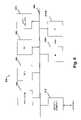
- FIG. 5illustrates one embodiment of the display or cover attached to a base with one link.
- FIG. 6shows a general computer architecture that can be used as a client or as a server computer.
- FIG. 7shows another embodiment of a complete architecture.
- FIGS. 1A–1Gshow a sequence of opening a cover from a closed position to an open position.
- the covercan include a display.
- the display 102is shown in a closed position i.e. in that the display covers the majority of the base 104 and that the display 102 in the closed position is the most compact configuration of the embodiment.
- the baseincludes a track 106 .
- the display 102includes an engagement 108 that engages the track 106 .
- the display 102also has a link 110 that is attached to the display 102 at an approximate midpoint location of the display 102 .
- the link 110can also pivot 112 in the display 102 .
- the link 110is attached to the base 104 at a fixed main pivot 112 in the base 104
- the link 110is attached to the display 102 is also a fixed pivoting point 114 on the display 102 .
- the link 110can also be a fixed length.
- FIGS. 1B–1Gillustrates several positions 102 A–G of the display 102 as the display 102 moves from a closed position 102 A to an open position 102 G.
- the several positions 102 A–Gillustrate movement and only one position is shown in solid lines, e.g., in FIG. 1B position 102 B solid lines.
- the solid lined positionis discussed in the corresponding illustration.
- FIG. 1Bthe display 102 moves as pressure is applied to the forward end 116 of the display 102 as shown by the push arrow. As shown, the display 102 is moved from the phantom position 102 A slightly rearward in the base 102 . The rear end 118 of the display 102 has risen substantially above the base 104 because the link 110 has a fixed length and has a fixed position on the display 102 and in the base 104 .
- FIG. 1Cthe position of the forward end 116 of the display 102 has been pushed further rearward. Previous positions 102 A, 102 B are also shown in phantom. In FIG. 1C , the rear end 118 of the display 102 has risen even further above the base 104 . The display 102 is raised because the relationship of the engagement 108 and the main pivot 112 and the length of the link 110 .
- the rear end 118 of the display 102is further raised above the base 104 .
- the link 110is substantially perpendicular to the base 104 .
- the engagement 108is maintained in the track 106 throughout all positions 102 A–G.
- FIG. 1Ethe forward end 116 of the display 102 has been pressed further rearward.
- the link 110has pivoted in the main pivot 112 beyond perpendicular, so that the display 102 has moved into an over center position 102 E. Because the display 102 is over center, then the height of the rear end 118 of the display 102 is beginning to drop down toward the base 104 .
- the engagement 108is still engaged in the track 106 and therefore the forward end 116 of the display 102 has maintained a substantially constant height from the base 104 .
- FIG. 1Fthe rear edge 118 of the display 102 is lowered further toward a horizontal position 102 G.
- FIG. 1Gthe display 102 is in the full open position 102 G.
- FIGS. 1A–Gallow a display or other cover 102 to open in a base 104 and yet not require slides similar to a drawer. Instead of drawer-type slides the display 102 opens in a somewhat arched path.
- FIG. 2illustrates one embodiment of the main pivot 212 .
- the main pivot 212includes a shaft or an axle 236 about which the link 210 pivots.
- the axle 236can also include a tensioner 232 .
- the tensioner 232can provide some amount of tension to the link 210 .
- the tensioner 230could be an open-tension tensioner.
- the tensioner 232could be a wound spring so that tension is always applied to the link 210 that pulls the display 102 toward a full open position such as position 102 G shown in FIG. 1G above.
- the display 202could include a latch that secures the display 202 in the closed position (such as position 102 A shown in FIG. 1A ). Disengaging the latch such as by pushing the display 202 rearward, or a separate latch disengagement device, allows the tensioner 232 to draw the display 202 through intermediate positions (e.g. positions 102 B–F described above) to the fully open position (e.g. position 102 G described above).
- a latchthat secures the display 202 in the closed position (such as position 102 A shown in FIG. 1A ).
- Disengaging the latchsuch as by pushing the display 202 rearward, or a separate latch disengagement device, allows the tensioner 232 to draw the display 202 through intermediate positions (e.g. positions 102 B–F described above) to the fully open position (e.g. position 102 G described above).
- the tensioner 232holds the display in the closed position such as position 102 A described in FIG. 1A above.
- the tensioner 232would therefore allow the display 202 to close more easily.
- the tensioner 232could be simply reversed from the above-described opening tensioner 232 .
- a latchcould hold the display 202 in the fully open position (e.g. position 102 G above) and then when the latch is disengaged, the display 202 would automatically move to the closed position (e.g. position 102 A described above).
- a full open positione.g. position 102 G described above
- a full closed positione.g. position 102 A described above
- a usermay wish to position the display 202 in an elevated or inclined position such as positions 102 E or 102 F described above. Therefore in one embodiment, détentes or other latch-type devices could be included in the main pivot 112 and/or the fixed pivoting point 114 and/or the link 110 so that the display 102 can be set to any of the positions 102 A–G.
- the tensioner 232can include an “over-center” type tension.
- An over-center type tensionprovides tension toward the closed position 102 A when the display 202 is in the first half of the motion from closed to open (i.e. positions 102 A–C).
- the over-center type tensionalso provides tension toward the open position 102 G when the display 202 is in the second half of the motion from closed to open (i.e. positions 102 E–G).
- the over-center tensionallows the display 202 to be easily held in both the open 102 G and closed 102 A positions without requiring additional latch devices.
- One embodiment of an over-center type tensionerincludes a cam mounted on the shaft 236 that applies pressure against a spring arm such as 233 and/or 234 of the tensioner 232 .
- the campresses upward on the spring arm 233 .
- the camis applying the maximum pressure on the spring arm 233 .
- the spring arm 233 pressure on the camcauses the display 202 to move toward the full open position 102 G.
- FIG. 3illustrates one embodiment of the link 310 and a damper 340 .
- the damper 340damps or slows the rotational motion of the link 310 about the main pivot 312 .
- the link 310includes a full or partial wheel 338 .
- the wheel 338follows the rotation of the link 310 .
- the wheel 338is in contact with a damper 340 .
- the damper 340provides resistance to rotation in either direction (i.e. open or closed directions) as the link 310 rotates in open or closed directions.
- the damper 340can be any type of damper known in the art.
- the damper 340may be a frictional braking device on the wheel 338 such as one or more fixed rubber (or similar frictional material) wedges or belts or drums applying friction against the wheel 338 .
- the damper 340could rotate and include a resistance mechanism within the damper 340 that resists rotation.
- the damper 340can be in frictional contact with the wheel 338 .
- the damper 340 and the wheel 338can include intermeshing gears such that as the link 310 rotates about the main pivot 312 , the wheel 338 follows the rotation of the link 310 and the wheel 338 causes the damper 340 to rotate.
- the resistance mechanism in the damper 340thereby damps the movement of the link 310 .
- FIG. 4illustrates one embodiment of the display or cover 402 on a base 404 .
- the cover 402is attached to the base 404 by two links 410 , 411 .
- the links 410 , 411are attached to the base 404 by main pivots 412 , 413 respectively.
- the links 410 , 411are attached to the cover 402 by fixed pivots 414 , 415 respectively.
- the cover 402is also attached to the base 404 by one or more tracks and engagements such engagement 108 and track 106 as described in FIGS. 1A–G above. While two links 410 , 411 are shown, additional or fewer links could also be used.
- FIG. 4Also illustrated in FIG. 4 is a keyboard 450 disposed on the upper surface of the base 404 .
- the keyboardis covered when the display 402 is in a closed position and exposed as the display is moved to an open position, as described herein.
- FIG. 5illustrates one embodiment of a base 504 and a cover 502 attached to the base 504 by a single link 510 .
- the cover 502can include a display and can also be moveable similar to as described in FIGS. 1A–G above. As shown, the cover 502 is in a position substantially similar to position 102 C described in FIG. 1C above.
- the link 510is shown mounted in a substantially central location but the link can be offset to one side or the other.
- the base 504also includes latches 542 , 543 . In one embodiment, the latches 542 , 543 engage the cover 502 when the cover is in the closed position (i.e. position 102 A shown in FIG.
- latches 542 , 543secure the cover 502 in the closed position.
- the latches 542 , 543can engage the cover 502 in a full open position (i.e. position 102 G shown in FIG. 1G above) so that the latches 542 , 543 secure the cover 502 in the open position.
- the link 510can also include a tensioner such as the tensioner 236 described in FIG. 2 above.
- the link 510can also include a damper such as the damper 340 described FIG. 3 above.
- FIG. 6is a high-level block diagram of one embodiment of the processing architecture the client 701 , and/or or the computers/servers with which the client communicates.
- the computer system 600includes a processor 602 , ROM 604 , and RAM 606 , each connected to a bus system 608 .
- the bus system 608may include one or more buses connected to each other through various bridges, controllers and/or adapters, such as are well known in the art.
- the bus system 608may include a “system bus” that is connected through an adapter to one or more expansion buses, such as a Peripheral Component Interconnect (PCI) bus.
- PCIPeripheral Component Interconnect
- Also coupled to the bus system 608are a mass storage device 610 , a network interface 612 , and a number (N) of input/output (I/O) devices 616 - 1 through 616 -N.
- I/Oinput/output
- I/O devices 616 - 1 through 616 -Nmay include, for example, a keyboard, a pointing device, a display device and/or other conventional I/O devices.
- Mass storage device 610may include one or more of any suitable device for storing large volumes of data, such as a magnetic disk or tape, magneto-optical (MO) storage device, or any of various types of Digital Versatile Disk (DVD) or Compact Disk (CD) based storage.
- Network interface 612provides data communication between the computer system 600 and other computer systems.
- Network interface 612may be any device suitable for or enabling the computer system 600 to communicate data with a remote processing system over a data communication link, such as a conventional telephone modem, an Integrated Services Digital Network (ISDN) adapter, a Digital Subscriber Line (DSL) adapter, a cable modem, a satellite transceiver, a wireless cellular transceiver, an Ethernet adapter, or the like.
- ISDNIntegrated Services Digital Network
- DSLDigital Subscriber Line
- FIG. 7illustrates a more detailed embodiment of a client computing device.
- the client computing devicemay be constructed in the physical form of the cover and base combination described in FIGS. 1 A–G and 2 – 5 above.
- the client computing device 700is comprised generally of a microcontroller 705 , an external memory 750 , a display controller 775 , and a battery 760 .
- the external memory 750may be used to store programs and/or data 765 transmitted to the client computing device 700 from a server 110 or other computer system.
- the external memory 750is non-volatile memory (e.g., an electrically erasable programmable read only memory (“EEPROM”); a programmable read only memory (“PROM”), etc).
- EEPROMelectrically erasable programmable read only memory
- PROMprogrammable read only memory
- the memory 750may be a volatile memory (e.g., random access memory or “RAM”) but the data stored therein may be continually maintained via the battery 760 .
- the battery 760in one embodiment is a coin cell battery (e.g., of the same type used in portable electronic devices such as calculators and watches).
- the microcontroller 705 of one embodimentis comprised of a central processing unit (“CPU”) 710 , a read only memory (“ROM”) 770 , and a scratchpad RAM 740 .
- the ROM 770is further comprised of an interpreter module 720 and a toolbox module 730 .
- the toolbox module 730 of the ROM 770contains a set of toolbox routines for processing data, text and graphics on the client computing device 700 . These routines include drawing text and graphics on the client computing device's display, decompressing data transmitted from the server, reproducing audio on the client computing device 700 , and performing various input/output and communication functions. A variety of additional client computing device functions may be included within the toolbox 730 while still complying with the underlying principles of the invention.
- microprograms and data 760are transmitted from the server to the external memory 750 of the client computing device via a communication interface 780 under control of the CPU 710 .
- Various communication interfaces 780may be employed without departing from the underlying principles of the invention including, for example, a Universal Serial Bus (“USB”) interface or a serial communication (“serial”) interface.
- the communication device 780may also include any other similar RF receiver/transmitter combination that will allow the microcontroller 705 to establish a link to a server.
- the client computing device 700transmits and receives data to/from a cellular network via the general packet radio service (“GPRS”).
- GPRSgeneral packet radio service
- the GPRS standardis a digital wireless packet switched standard.
- Embodiments of the client computing devicemay also be configured to transmit/receive data using a variety of other communication standards including 2-way paging standards and third generation (“3G”) wireless standards (e.g., UTMS, CDMA 2000, NTT DoCoMo, . . . etc).
- 3Gthird generation
- the microprograms in one embodimentare comprised of compact, interpreted instructions known as “bytecodes,” which are converted into native code by the interpreter module 720 before being executed by the CPU 710 .
- bytecodescompact, interpreted instructions
- One of the benefits of this configurationis that when the microcontroller/CPU portion of the client computing device 700 is upgraded (e.g., to a faster and/or less expensive model), only the interpreter module 720 and toolbox 730 of the ROM needs to be rewritten to interpret the currently existing bytecodes for the new microcontroller/CPU.
- this configurationallows client computing devices 700 with different CPUs to coexist and execute the same microprograms.
- new interpreter modules 720 and/or toolbox routines 730may be developed to execute the same microprograms on cellular phones, personal information managers (“PIMs”), or any other device with a CPU and memory.
- ROM 770may be comprised of interpreted code as well as native code written specifically for the microcontroller CPU 705 . More particularly, some toolbox routines may be written as interpreted code (as indicated by the arrow between the toolbox 730 and the interpreter module 720 ) to conserve memory and bandwidth for the same reasons described above with respect to microprograms. Moreover, in one embodiment, data and microprograms stored in external memory 750 may be configured to override older versions of data/microprograms stored in the ROM 770 (e.g., in the ROM toolbox 730 ).
- the CPU 705employs a 32-bit RISC-based microprocessor such as an ARM processor.
- ARM processorsare widely used in PDAs, cell phones and a variety of other wireless devices. It should be noted, however, that various other hardware and software (and/or firmware) architectures may be used for the client computing device 700 while still complying with the underlying principles of the invention.
Landscapes
- Engineering & Computer Science (AREA)
- Theoretical Computer Science (AREA)
- Computer Hardware Design (AREA)
- Physics & Mathematics (AREA)
- Human Computer Interaction (AREA)
- General Engineering & Computer Science (AREA)
- General Physics & Mathematics (AREA)
- Mathematical Physics (AREA)
- Devices For Indicating Variable Information By Combining Individual Elements (AREA)
- Casings For Electric Apparatus (AREA)
Abstract
Description
Claims (21)
Priority Applications (2)
| Application Number | Priority Date | Filing Date | Title |
|---|---|---|---|
| PCT/US2002/027638WO2003021408A2 (en) | 2001-08-29 | 2002-08-29 | Sliding display apparatus |
| US10/232,127US7107084B2 (en) | 2001-08-29 | 2002-08-29 | Sliding display apparatus |
Applications Claiming Priority (2)
| Application Number | Priority Date | Filing Date | Title |
|---|---|---|---|
| US31597101P | 2001-08-29 | 2001-08-29 | |
| US10/232,127US7107084B2 (en) | 2001-08-29 | 2002-08-29 | Sliding display apparatus |
Publications (2)
| Publication Number | Publication Date |
|---|---|
| US20030109230A1 US20030109230A1 (en) | 2003-06-12 |
| US7107084B2true US7107084B2 (en) | 2006-09-12 |
Family
ID=26925704
Family Applications (1)
| Application Number | Title | Priority Date | Filing Date |
|---|---|---|---|
| US10/232,127Expired - Fee RelatedUS7107084B2 (en) | 2001-08-29 | 2002-08-29 | Sliding display apparatus |
Country Status (2)
| Country | Link |
|---|---|
| US (1) | US7107084B2 (en) |
| WO (1) | WO2003021408A2 (en) |
Cited By (53)
| Publication number | Priority date | Publication date | Assignee | Title |
|---|---|---|---|---|
| US20040254000A1 (en)* | 2003-05-19 | 2004-12-16 | Benq Corporation | Folding electronic device |
| US20050277451A1 (en)* | 2004-06-09 | 2005-12-15 | Benq Corporation | Portable electronic apparatus |
| US20060027432A1 (en)* | 2004-08-05 | 2006-02-09 | Nifco Inc. | One-way damper and electronic devices using the one-way damper |
| US20060137141A1 (en)* | 2003-08-18 | 2006-06-29 | Katoh Electrical Machinery Co., Ltd. | Slide hinge for small-sized information terminal |
| US20060229115A1 (en)* | 2005-04-12 | 2006-10-12 | Jari Puranen | Multifunction electronic device |
| US20070082695A1 (en)* | 2005-10-07 | 2007-04-12 | Samsung Electronics Co., Ltd. | Portable communication apparatus |
| US20070105606A1 (en)* | 2005-11-07 | 2007-05-10 | Samsung Electronics Co., Ltd. | Mobile phone with a sliding cradle for providing visual and acoustic convenience |
| US20070279241A1 (en)* | 2006-05-31 | 2007-12-06 | Searete Llc, A Limited Liability Corporation Of The State Of Delaware | Vehicle control and communication via device in proximity |
| US20080030936A1 (en)* | 2006-08-01 | 2008-02-07 | Christopher James Dawson | Display system for use with portable display device |
| US20080176603A1 (en)* | 2007-01-22 | 2008-07-24 | Inventec Corporation | Portable electronic device |
| US20080304217A1 (en)* | 2007-06-05 | 2008-12-11 | Asustek Computer Inc. | Portable electronic device |
| US20080311963A1 (en)* | 2005-04-06 | 2008-12-18 | Andrew Strawn | Extensible Mobile Electronic Device |
| US20090049646A1 (en)* | 2007-08-20 | 2009-02-26 | Google Inc. | Electronic Device with Hinge Mechanism |
| US20090111543A1 (en)* | 2007-10-31 | 2009-04-30 | Hong Fu Jin Precision Industry (Shenzhen) Co., Ltd. | Protective sleeve for portable electronic devices |
| US20090168369A1 (en)* | 2007-12-28 | 2009-07-02 | Nokia Corporation | Electronic device slide and tilt mechanism |
| US20100000052A1 (en)* | 2008-07-03 | 2010-01-07 | Chia-Ko Chung | Slide hinge |
| US20100046149A1 (en)* | 2008-08-25 | 2010-02-25 | Htc Corporation | Sliding electronic device |
| US20100055552A1 (en)* | 2008-08-29 | 2010-03-04 | Fih (Hong Kong) Limited | Battery cover structure |
| US20100072334A1 (en)* | 2008-09-09 | 2010-03-25 | Zero Chroma, LLC | Holder for Electronic Device with Support |
| US20100160010A1 (en)* | 2006-07-19 | 2010-06-24 | Ladouceur Norman M | Handheld mobile communication device with moveable display/cover member |
| US20100232097A1 (en)* | 2009-03-10 | 2010-09-16 | Nokia Corporation | Extendible apparatus |
| US20110023272A1 (en)* | 2009-07-28 | 2011-02-03 | Shin Zu Shing Co., Ltd. | Hinge mechanism and an eletronic device therewith |
| US20110031287A1 (en)* | 2008-09-09 | 2011-02-10 | Zero Chroma, LLC | Holder for Electronic Device with Support |
| US20110075340A1 (en)* | 2008-06-18 | 2011-03-31 | Biao Qin | Portable Electronic Computer |
| US20110122555A1 (en)* | 2009-11-24 | 2011-05-26 | Htc Corporation | Electronic device |
| US20110157793A1 (en)* | 2009-12-30 | 2011-06-30 | Hong Fu Jin Precision Industry (Shenzhen) Co., Ltd. | Slide-type electronic device |
| US20110195760A1 (en)* | 2010-02-05 | 2011-08-11 | Sony Ericsson Mobile Communications Ab | Fully flat slider |
| US20120176741A1 (en)* | 2011-01-11 | 2012-07-12 | Flextronics Id, Llc | Multi-positionable portable computer |
| US8300394B2 (en) | 2010-06-15 | 2012-10-30 | Hewlett-Packard Development Company, L.P. | Track guided hinge for a portable electronic device |
| US20120300411A1 (en)* | 2011-05-26 | 2012-11-29 | Hon Hai Precision Industry Co., Ltd. | Display module having adjustable view angle function |
| US20130128442A1 (en)* | 2011-11-18 | 2013-05-23 | Wistron Corporation | Portable Computer |
| US8526178B2 (en) | 2011-05-17 | 2013-09-03 | Flextronics Ap, Llc | All-in-one computing device with an adjustable screen height |
| US20130286558A1 (en)* | 2012-04-25 | 2013-10-31 | Hon Hai Precision Industry Co., Ltd. | Portable electronic device and protector |
| US8606340B2 (en) | 2010-11-22 | 2013-12-10 | Blackberry Limited | Multi-display mobile device |
| US8613551B2 (en)* | 2012-03-09 | 2013-12-24 | First Dome Corporation | Slide rail structure for electronic device |
| USD698543S1 (en) | 2012-10-19 | 2014-02-04 | Zerochroma, LLC | Portion of holder for electronic device |
| US8648821B2 (en) | 2011-01-18 | 2014-02-11 | Flextronics Id, Llc | Spheroidal pivot for an electronic device |
| USD700600S1 (en) | 2012-09-10 | 2014-03-04 | Google Inc. | Display and base portion of a computing device |
| US8681113B1 (en) | 2011-09-27 | 2014-03-25 | Flextronics Ap, Llc | Concept and operation mode for multi media AIO |
| US20140145938A1 (en)* | 2012-11-27 | 2014-05-29 | Lenovo (Beijing) Co., Ltd. | Electronic device and information processing method thereof |
| CN103869889A (en)* | 2012-12-14 | 2014-06-18 | 纬创资通股份有限公司 | Rotating mechanism and related electronic device |
| US8770538B2 (en)* | 2012-01-31 | 2014-07-08 | First Dome Corporation | Supporting structure for electronic device |
| US20140254079A1 (en)* | 2013-03-05 | 2014-09-11 | Wistron Corp. | Electronic device |
| US20140355186A1 (en)* | 2013-05-28 | 2014-12-04 | Sony Corporation | Electronic device |
| US8960634B2 (en) | 2008-09-09 | 2015-02-24 | Zero Chroma, LLC | Holder for electronic device with support |
| US9001504B2 (en) | 2010-12-28 | 2015-04-07 | Google Inc. | Moveable display portion of a computing device |
| US9477262B2 (en) | 2012-09-10 | 2016-10-25 | Google Inc. | Moveable display portion of a computing device including a clutch mechanism |
| TWI582567B (en)* | 2015-06-05 | 2017-05-11 | 宏碁股份有限公司 | Electronic device |
| US9740240B1 (en) | 2016-03-21 | 2017-08-22 | Google Inc. | Base with rotating mount that increases friction of rotation when portable computing device is placed onto mount |
| US20170265622A1 (en)* | 2016-03-15 | 2017-09-21 | HCT Group Holdings Limited | Double fold compact |
| US10737849B2 (en) | 2016-12-23 | 2020-08-11 | Carnes Company, Inc. | Enclosure with sliding and pivoting cover |
| US11287844B2 (en)* | 2020-01-02 | 2022-03-29 | Qisda Corporation | Support base and display device |
| US12311569B2 (en) | 2020-04-14 | 2025-05-27 | Woodland Mills Inc. | Portable sawmill with folding bed |
Families Citing this family (22)
| Publication number | Priority date | Publication date | Assignee | Title |
|---|---|---|---|---|
| US6847519B2 (en) | 2002-06-28 | 2005-01-25 | Nokia Corporation | Phone with automatic linked qwerty keyboard |
| US6903927B2 (en)* | 2002-12-17 | 2005-06-07 | Nokia Corporation | Convertible mobile computing device |
| KR101029809B1 (en)* | 2004-02-04 | 2011-04-20 | 엘지전자 주식회사 | Slide type mobile terminal |
| KR101115377B1 (en)* | 2005-04-28 | 2012-02-15 | 엘지전자 주식회사 | Mobile communication terminal with display unit sliding device |
| KR101171395B1 (en) | 2005-09-09 | 2012-08-07 | 삼성전자주식회사 | Handheld terminal |
| US20070121279A1 (en)* | 2005-11-25 | 2007-05-31 | Motorola, Inc. | Translating axes slide mechanism |
| US7725988B2 (en)* | 2006-02-15 | 2010-06-01 | Lg Electronics Inc. | Hinge assembly and mobile device having the same |
| JP4658849B2 (en)* | 2006-03-31 | 2011-03-23 | ブラザー工業株式会社 | Electronics |
| KR100833241B1 (en)* | 2006-04-28 | 2008-05-28 | 삼성전자주식회사 | Sliding-tilt unit and mobile appliance adopting the same |
| EP1881680B1 (en) | 2006-07-19 | 2016-09-14 | BlackBerry Limited | Handheld mobile communication device with slidable display/cover member |
| CN101469736B (en)* | 2007-12-27 | 2012-03-28 | 鸿富锦精密工业(深圳)有限公司 | hinge structure |
| US8020254B2 (en)* | 2008-12-04 | 2011-09-20 | Shin Zu Shing Co., Ltd | Hinge assembly |
| US8103322B2 (en) | 2009-02-27 | 2012-01-24 | Research In Motion Limited | Handheld electronic device having two device members slidable relative to a bridge |
| KR101027096B1 (en)* | 2009-06-01 | 2011-04-05 | 주식회사 팬택 | Hinge assembly and portable terminal having same |
| CN101995919A (en)* | 2009-08-26 | 2011-03-30 | 鸿富锦精密工业(深圳)有限公司 | Portable computer |
| KR101101073B1 (en)* | 2010-02-11 | 2011-12-30 | 주식회사 팬택 | terminal |
| CN201781710U (en)* | 2010-07-30 | 2011-03-30 | 国基电子(上海)有限公司 | Portable electronic device |
| KR101213692B1 (en)* | 2011-03-28 | 2012-12-18 | 솔로몬테크놀로지 주식회사 | COMPLEX HINGE APPARATUS AND DIFFERENT MEANING COMPLEX HINGE APPARATUS THEe CELL PHONE |
| JP5214812B1 (en)* | 2012-01-10 | 2013-06-19 | 株式会社東芝 | Electronics |
| TWI480720B (en) | 2012-07-24 | 2015-04-11 | Quanta Comp Inc | Portable electrical device |
| TWI598018B (en) | 2014-01-02 | 2017-09-01 | 仁寶電腦工業股份有限公司 | Portable electric device |
| JP2014082789A (en)* | 2014-01-28 | 2014-05-08 | Fujitsu Ltd | Portable apparatus |
Citations (35)
| Publication number | Priority date | Publication date | Assignee | Title |
|---|---|---|---|---|
| US4237540A (en) | 1978-03-01 | 1980-12-02 | Olympus Optical Company Limited | Tape recorder with table computer |
| US4718740A (en) | 1986-10-28 | 1988-01-12 | Allied Corporation | Housing and stowage mechanism for terminal keyboard and display panel |
| US5168426A (en)* | 1991-08-16 | 1992-12-01 | Beaver Computer Corporation | Hinge mechanism for cover panel of portable computer including slide mechanism |
| US5224060A (en) | 1992-07-29 | 1993-06-29 | Ma Hsi Kuang | Mobile computer with pen base/keyboard input modes |
| US5268817A (en) | 1990-04-27 | 1993-12-07 | Kabushiki Kaisha Toshiba | Portable computer with keyboard and having display with coordinate input tablet rotatably mounted to face either toward or away from keyboard when closed over keyboard |
| US5278779A (en) | 1992-06-26 | 1994-01-11 | Conway Kevin M | Laptop computer with hinged keyboard |
| US5345362A (en) | 1993-04-29 | 1994-09-06 | Medtronic, Inc. | Portable computer apparatus with articulating display panel |
| JPH06324759A (en) | 1993-05-14 | 1994-11-25 | Sharp Corp | Information processing equipment |
| US5510806A (en)* | 1993-10-28 | 1996-04-23 | Dell Usa, L.P. | Portable computer having an LCD projection display system |
| US5548478A (en)* | 1994-07-25 | 1996-08-20 | Khyber Technologies Corporation | Portable computing device having an adjustable hinge |
| US5628817A (en) | 1994-11-15 | 1997-05-13 | Outokumpu Engineering Contractors Oy | Method for leaching nickel-copper matte employing substantially neutral leaching solutions |
| US5638257A (en) | 1995-01-27 | 1997-06-10 | Khyber Technologies Corporation | Combination keyboard and cover for a handheld computer |
| JPH1055227A (en) | 1996-08-09 | 1998-02-24 | Sharp Corp | Information processing device |
| US5900848A (en) | 1996-05-17 | 1999-05-04 | Sharp Kabushiki Kaisha | Information processing apparatus |
| JPH11161367A (en) | 1997-11-27 | 1999-06-18 | Seiko Instruments Inc | Portable information processor |
| US5949408A (en) | 1995-09-28 | 1999-09-07 | Hewlett-Packard Company | Dual orientation display handheld computer devices |
| US6020878A (en) | 1998-06-01 | 2000-02-01 | Motorola, Inc. | Selective call radio with hinged touchpad |
| EP1009104A2 (en)* | 1998-12-11 | 2000-06-14 | Ace Technology | Wireless telephone capable of automatically opening a flip |
| US6108716A (en) | 1996-10-28 | 2000-08-22 | Hitachi, Ltd. | Data processing unit |
| US6129237A (en)* | 1997-12-08 | 2000-10-10 | Casio Computer Co., Ltd. | Structure for opening/closing a case cover |
| US6134103A (en) | 1998-10-30 | 2000-10-17 | Ghanma; Tony | Flat panel display with adjustable height for a portable computer |
| US6157717A (en)* | 1998-03-19 | 2000-12-05 | Qualcomm Incorporated | Snap hinge mechanism for flip style portable phone |
| US6191938B1 (en) | 1993-10-29 | 2001-02-20 | Kabushiki Kaisha Toshiba | Electronic apparatus having switch operated by rotatable display-unit |
| US20020075281A1 (en) | 2000-09-07 | 2002-06-20 | Satoshi Suzuki | Image transferring apparatus and method, file transferring apparatus and method, and program storage medium |
| US6433777B1 (en) | 1999-09-29 | 2002-08-13 | Gateway, Inc. | Apparatus for extending a cursor control stick |
| US6446004B1 (en) | 2001-02-28 | 2002-09-03 | International Business Machines Corporation | System and method for implementing proximity or location driven activities |
| US6482445B1 (en) | 2001-03-29 | 2002-11-19 | Nel Biotech Co., Ltd. | Process for preparing stabilized liquid silicate carbonate antiseptic agents |
| US6507336B1 (en) | 1999-02-04 | 2003-01-14 | Palm, Inc. | Keyboard for a handheld computer |
| US6525715B2 (en) | 1997-03-24 | 2003-02-25 | Seiko Epson Corporation | Portable information acquisition device |
| US6539208B1 (en)* | 1999-11-16 | 2003-03-25 | Nec Corporation | Portable telephone apparatus |
| US6542721B2 (en)* | 1999-10-11 | 2003-04-01 | Peter V. Boesen | Cellular telephone, personal digital assistant and pager unit |
| US6618044B1 (en) | 2000-05-25 | 2003-09-09 | Palm Inc. | Selectively relocatable and universal interface module with circuitry for a display screen |
| US6622031B1 (en) | 2000-10-04 | 2003-09-16 | 3Com Corporation | Antenna flip-up on removal of stylus for handheld device |
| US6636419B2 (en)* | 2001-08-09 | 2003-10-21 | Danger, Inc. | Handheld display and keyboard |
| US6665173B2 (en) | 1999-12-20 | 2003-12-16 | Wireless Agents, Llc | Physical configuration of a hand-held electronic communication device |
- 2002
- 2002-08-29WOPCT/US2002/027638patent/WO2003021408A2/ennot_activeApplication Discontinuation
- 2002-08-29USUS10/232,127patent/US7107084B2/ennot_activeExpired - Fee Related
Patent Citations (37)
| Publication number | Priority date | Publication date | Assignee | Title |
|---|---|---|---|---|
| US4237540A (en) | 1978-03-01 | 1980-12-02 | Olympus Optical Company Limited | Tape recorder with table computer |
| US4718740A (en) | 1986-10-28 | 1988-01-12 | Allied Corporation | Housing and stowage mechanism for terminal keyboard and display panel |
| US5268817A (en) | 1990-04-27 | 1993-12-07 | Kabushiki Kaisha Toshiba | Portable computer with keyboard and having display with coordinate input tablet rotatably mounted to face either toward or away from keyboard when closed over keyboard |
| US5168426A (en)* | 1991-08-16 | 1992-12-01 | Beaver Computer Corporation | Hinge mechanism for cover panel of portable computer including slide mechanism |
| US5278779A (en) | 1992-06-26 | 1994-01-11 | Conway Kevin M | Laptop computer with hinged keyboard |
| US5224060A (en) | 1992-07-29 | 1993-06-29 | Ma Hsi Kuang | Mobile computer with pen base/keyboard input modes |
| US5345362A (en) | 1993-04-29 | 1994-09-06 | Medtronic, Inc. | Portable computer apparatus with articulating display panel |
| JPH06324759A (en) | 1993-05-14 | 1994-11-25 | Sharp Corp | Information processing equipment |
| US5510806A (en)* | 1993-10-28 | 1996-04-23 | Dell Usa, L.P. | Portable computer having an LCD projection display system |
| US6191938B1 (en) | 1993-10-29 | 2001-02-20 | Kabushiki Kaisha Toshiba | Electronic apparatus having switch operated by rotatable display-unit |
| US5548478A (en)* | 1994-07-25 | 1996-08-20 | Khyber Technologies Corporation | Portable computing device having an adjustable hinge |
| US5628817A (en) | 1994-11-15 | 1997-05-13 | Outokumpu Engineering Contractors Oy | Method for leaching nickel-copper matte employing substantially neutral leaching solutions |
| US5638257A (en) | 1995-01-27 | 1997-06-10 | Khyber Technologies Corporation | Combination keyboard and cover for a handheld computer |
| US5949408A (en) | 1995-09-28 | 1999-09-07 | Hewlett-Packard Company | Dual orientation display handheld computer devices |
| US5900848A (en) | 1996-05-17 | 1999-05-04 | Sharp Kabushiki Kaisha | Information processing apparatus |
| JPH1055227A (en) | 1996-08-09 | 1998-02-24 | Sharp Corp | Information processing device |
| US6108716A (en) | 1996-10-28 | 2000-08-22 | Hitachi, Ltd. | Data processing unit |
| US6525715B2 (en) | 1997-03-24 | 2003-02-25 | Seiko Epson Corporation | Portable information acquisition device |
| JPH11161367A (en) | 1997-11-27 | 1999-06-18 | Seiko Instruments Inc | Portable information processor |
| US6129237A (en)* | 1997-12-08 | 2000-10-10 | Casio Computer Co., Ltd. | Structure for opening/closing a case cover |
| US6157717A (en)* | 1998-03-19 | 2000-12-05 | Qualcomm Incorporated | Snap hinge mechanism for flip style portable phone |
| US6020878A (en) | 1998-06-01 | 2000-02-01 | Motorola, Inc. | Selective call radio with hinged touchpad |
| US6134103A (en) | 1998-10-30 | 2000-10-17 | Ghanma; Tony | Flat panel display with adjustable height for a portable computer |
| EP1009104A2 (en)* | 1998-12-11 | 2000-06-14 | Ace Technology | Wireless telephone capable of automatically opening a flip |
| US6507336B1 (en) | 1999-02-04 | 2003-01-14 | Palm, Inc. | Keyboard for a handheld computer |
| US6433777B1 (en) | 1999-09-29 | 2002-08-13 | Gateway, Inc. | Apparatus for extending a cursor control stick |
| US6542721B2 (en)* | 1999-10-11 | 2003-04-01 | Peter V. Boesen | Cellular telephone, personal digital assistant and pager unit |
| US6539208B1 (en)* | 1999-11-16 | 2003-03-25 | Nec Corporation | Portable telephone apparatus |
| US6665173B2 (en) | 1999-12-20 | 2003-12-16 | Wireless Agents, Llc | Physical configuration of a hand-held electronic communication device |
| US6618044B1 (en) | 2000-05-25 | 2003-09-09 | Palm Inc. | Selectively relocatable and universal interface module with circuitry for a display screen |
| US20020075281A1 (en) | 2000-09-07 | 2002-06-20 | Satoshi Suzuki | Image transferring apparatus and method, file transferring apparatus and method, and program storage medium |
| US6622031B1 (en) | 2000-10-04 | 2003-09-16 | 3Com Corporation | Antenna flip-up on removal of stylus for handheld device |
| US6446004B1 (en) | 2001-02-28 | 2002-09-03 | International Business Machines Corporation | System and method for implementing proximity or location driven activities |
| US6482445B1 (en) | 2001-03-29 | 2002-11-19 | Nel Biotech Co., Ltd. | Process for preparing stabilized liquid silicate carbonate antiseptic agents |
| US6636419B2 (en)* | 2001-08-09 | 2003-10-21 | Danger, Inc. | Handheld display and keyboard |
| US20040062000A1 (en) | 2001-08-09 | 2004-04-01 | Duarte Matias G. | Handheld display and keyboard |
| US6836404B2 (en)* | 2001-08-09 | 2004-12-28 | Danger, Inc. | Handheld display and keyboard |
Non-Patent Citations (1)
| Title |
|---|
| Brandenbert, et al., "Physical Configuration Of A Handheld Electronic Communication Device", Provisional Application Filed Dec. 20, 1999, U.S. Appl. No. 60/172,675. |
Cited By (93)
| Publication number | Priority date | Publication date | Assignee | Title |
|---|---|---|---|---|
| US20040254000A1 (en)* | 2003-05-19 | 2004-12-16 | Benq Corporation | Folding electronic device |
| US7278184B2 (en)* | 2003-08-18 | 2007-10-09 | Katoh Electric Machinery Co., Ltd. | Slide hinge for small-sized information terminal |
| US20060137141A1 (en)* | 2003-08-18 | 2006-06-29 | Katoh Electrical Machinery Co., Ltd. | Slide hinge for small-sized information terminal |
| US20050277451A1 (en)* | 2004-06-09 | 2005-12-15 | Benq Corporation | Portable electronic apparatus |
| US7363068B2 (en)* | 2004-06-09 | 2008-04-22 | Benq Corporation | Portable electronic apparatus |
| US20060027432A1 (en)* | 2004-08-05 | 2006-02-09 | Nifco Inc. | One-way damper and electronic devices using the one-way damper |
| US7416063B2 (en)* | 2004-08-05 | 2008-08-26 | Nifco Inc. | One-way damper and electronic devices using the one-way damper |
| US9203938B2 (en)* | 2005-04-06 | 2015-12-01 | Nokia Technologies Oy | Extensible mobile electronic device |
| US20080311963A1 (en)* | 2005-04-06 | 2008-12-18 | Andrew Strawn | Extensible Mobile Electronic Device |
| US20060229115A1 (en)* | 2005-04-12 | 2006-10-12 | Jari Puranen | Multifunction electronic device |
| US7447528B2 (en)* | 2005-04-12 | 2008-11-04 | Nokia Corporation | Multifunction electronic device |
| US20070082695A1 (en)* | 2005-10-07 | 2007-04-12 | Samsung Electronics Co., Ltd. | Portable communication apparatus |
| US8666463B2 (en)* | 2005-10-07 | 2014-03-04 | Samsung Electronics Co., Ltd. | Portable communication apparatus with automatically rotating display by actuating a switch unit |
| US20070105606A1 (en)* | 2005-11-07 | 2007-05-10 | Samsung Electronics Co., Ltd. | Mobile phone with a sliding cradle for providing visual and acoustic convenience |
| US8086290B2 (en)* | 2005-11-07 | 2011-12-27 | Samsung Electronics Co., Ltd. | Mobile phone with a sliding cradle for providing visual and acoustic convenience |
| US20070279241A1 (en)* | 2006-05-31 | 2007-12-06 | Searete Llc, A Limited Liability Corporation Of The State Of Delaware | Vehicle control and communication via device in proximity |
| US8249676B2 (en)* | 2006-07-19 | 2012-08-21 | Research In Motion Limited | Handheld mobile communication device with moveable display/cover member |
| US20100160010A1 (en)* | 2006-07-19 | 2010-06-24 | Ladouceur Norman M | Handheld mobile communication device with moveable display/cover member |
| US7333323B1 (en)* | 2006-08-01 | 2008-02-19 | International Business Machines Corporation | Display system for use with portable display device |
| US20080030936A1 (en)* | 2006-08-01 | 2008-02-07 | Christopher James Dawson | Display system for use with portable display device |
| US7440266B2 (en)* | 2007-01-22 | 2008-10-21 | Inventec Corporation | Portable electronic device |
| US20080176603A1 (en)* | 2007-01-22 | 2008-07-24 | Inventec Corporation | Portable electronic device |
| US20080304217A1 (en)* | 2007-06-05 | 2008-12-11 | Asustek Computer Inc. | Portable electronic device |
| US20090049646A1 (en)* | 2007-08-20 | 2009-02-26 | Google Inc. | Electronic Device with Hinge Mechanism |
| US8488778B2 (en) | 2007-08-20 | 2013-07-16 | Google Inc. | Electronic device with hinge mechanism |
| US8099144B2 (en) | 2007-08-20 | 2012-01-17 | Google Inc. | Electronic device with hinge mechanism |
| US8295043B2 (en)* | 2007-10-31 | 2012-10-23 | Hong Fu Jin Precision Industry (Shenzhen) Co., Ltd. | Protective sleeve for portable electronic devices |
| US20090111543A1 (en)* | 2007-10-31 | 2009-04-30 | Hong Fu Jin Precision Industry (Shenzhen) Co., Ltd. | Protective sleeve for portable electronic devices |
| US7751195B2 (en)* | 2007-12-28 | 2010-07-06 | Nokia Corporation | Electronic device slide and tilt mechanism |
| US20090168369A1 (en)* | 2007-12-28 | 2009-07-02 | Nokia Corporation | Electronic device slide and tilt mechanism |
| US20110075340A1 (en)* | 2008-06-18 | 2011-03-31 | Biao Qin | Portable Electronic Computer |
| US9841794B2 (en)* | 2008-06-18 | 2017-12-12 | Shenzhen Qin Bo Core Technology Development Co., Ltd. | Portable electronic computer |
| US20100000052A1 (en)* | 2008-07-03 | 2010-01-07 | Chia-Ko Chung | Slide hinge |
| US8200300B2 (en)* | 2008-08-25 | 2012-06-12 | Htc Corporation | Sliding electronic device |
| US20100046149A1 (en)* | 2008-08-25 | 2010-02-25 | Htc Corporation | Sliding electronic device |
| US20100055552A1 (en)* | 2008-08-29 | 2010-03-04 | Fih (Hong Kong) Limited | Battery cover structure |
| US8257850B2 (en)* | 2008-08-29 | 2012-09-04 | Fih (Hong Kong) Limited | Battery cover structure |
| US9267638B2 (en) | 2008-09-09 | 2016-02-23 | Zero Chroma, LLC | Holder for electronic device with support |
| US9538675B2 (en) | 2008-09-09 | 2017-01-03 | Zero Chroma, Llc. | Holder for electronic device with support |
| US8960634B2 (en) | 2008-09-09 | 2015-02-24 | Zero Chroma, LLC | Holder for electronic device with support |
| US20110031287A1 (en)* | 2008-09-09 | 2011-02-10 | Zero Chroma, LLC | Holder for Electronic Device with Support |
| US20100072334A1 (en)* | 2008-09-09 | 2010-03-25 | Zero Chroma, LLC | Holder for Electronic Device with Support |
| US8382059B2 (en) | 2008-09-09 | 2013-02-26 | Zero Chroma, LLC | Holder for electronic device with support |
| US20100232097A1 (en)* | 2009-03-10 | 2010-09-16 | Nokia Corporation | Extendible apparatus |
| US8199487B2 (en)* | 2009-03-10 | 2012-06-12 | Nokia Corporation | Extendible apparatus |
| US20110023272A1 (en)* | 2009-07-28 | 2011-02-03 | Shin Zu Shing Co., Ltd. | Hinge mechanism and an eletronic device therewith |
| US8108970B2 (en)* | 2009-07-28 | 2012-02-07 | Shin Zu Shing Co., Ltd. | Hinge mechanism and an electronic device therewith |
| US8199475B2 (en)* | 2009-11-24 | 2012-06-12 | Htc Corporation | Electronic device |
| TWI401560B (en)* | 2009-11-24 | 2013-07-11 | Htc Corp | Electronic device |
| US20110122555A1 (en)* | 2009-11-24 | 2011-05-26 | Htc Corporation | Electronic device |
| US20110157793A1 (en)* | 2009-12-30 | 2011-06-30 | Hong Fu Jin Precision Industry (Shenzhen) Co., Ltd. | Slide-type electronic device |
| US20110195760A1 (en)* | 2010-02-05 | 2011-08-11 | Sony Ericsson Mobile Communications Ab | Fully flat slider |
| US8744538B2 (en)* | 2010-02-05 | 2014-06-03 | Sony Mobile Communications Ab | Fully flat slider |
| US8300394B2 (en) | 2010-06-15 | 2012-10-30 | Hewlett-Packard Development Company, L.P. | Track guided hinge for a portable electronic device |
| US8606340B2 (en) | 2010-11-22 | 2013-12-10 | Blackberry Limited | Multi-display mobile device |
| US9001504B2 (en) | 2010-12-28 | 2015-04-07 | Google Inc. | Moveable display portion of a computing device |
| US20120176741A1 (en)* | 2011-01-11 | 2012-07-12 | Flextronics Id, Llc | Multi-positionable portable computer |
| US8649166B2 (en)* | 2011-01-11 | 2014-02-11 | Z124 | Multi-positionable portable computer |
| US9152263B1 (en) | 2011-01-18 | 2015-10-06 | Z124 | Spheroidal pivot for an electronic device |
| US9152171B1 (en) | 2011-01-18 | 2015-10-06 | Z124 | Spheroidal pivot for an electronic device |
| US9152172B1 (en) | 2011-01-18 | 2015-10-06 | Z124 | Spheroidal pivot for an electronic device |
| US8648821B2 (en) | 2011-01-18 | 2014-02-11 | Flextronics Id, Llc | Spheroidal pivot for an electronic device |
| US8526178B2 (en) | 2011-05-17 | 2013-09-03 | Flextronics Ap, Llc | All-in-one computing device with an adjustable screen height |
| US20120300411A1 (en)* | 2011-05-26 | 2012-11-29 | Hon Hai Precision Industry Co., Ltd. | Display module having adjustable view angle function |
| US8587948B2 (en)* | 2011-05-26 | 2013-11-19 | Hong Fu Jin Precision Industry (Shenzhen) Co., Ltd. | Display module having adjustable view angle function |
| US8681113B1 (en) | 2011-09-27 | 2014-03-25 | Flextronics Ap, Llc | Concept and operation mode for multi media AIO |
| US20150331457A1 (en)* | 2011-11-18 | 2015-11-19 | Wistron Corporation | Portable Computer |
| US9218022B2 (en)* | 2011-11-18 | 2015-12-22 | Wistron Corporation | Portable computer |
| US9632529B2 (en)* | 2011-11-18 | 2017-04-25 | Wistron Corporation | Portable computer |
| US20130128442A1 (en)* | 2011-11-18 | 2013-05-23 | Wistron Corporation | Portable Computer |
| US8770538B2 (en)* | 2012-01-31 | 2014-07-08 | First Dome Corporation | Supporting structure for electronic device |
| US8613551B2 (en)* | 2012-03-09 | 2013-12-24 | First Dome Corporation | Slide rail structure for electronic device |
| US20130286558A1 (en)* | 2012-04-25 | 2013-10-31 | Hon Hai Precision Industry Co., Ltd. | Portable electronic device and protector |
| US9477262B2 (en) | 2012-09-10 | 2016-10-25 | Google Inc. | Moveable display portion of a computing device including a clutch mechanism |
| USD700600S1 (en) | 2012-09-10 | 2014-03-04 | Google Inc. | Display and base portion of a computing device |
| USD698543S1 (en) | 2012-10-19 | 2014-02-04 | Zerochroma, LLC | Portion of holder for electronic device |
| US9958899B2 (en)* | 2012-11-27 | 2018-05-01 | Beijing Lenovo Software Ltd. | Electronic device and information processing method thereof |
| CN103838562B (en)* | 2012-11-27 | 2019-03-08 | 联想(北京)有限公司 | Electronic equipment and its information processing method |
| CN103838562A (en)* | 2012-11-27 | 2014-06-04 | 联想(北京)有限公司 | Electronic equipment and information processing method thereof |
| US20140145938A1 (en)* | 2012-11-27 | 2014-05-29 | Lenovo (Beijing) Co., Ltd. | Electronic device and information processing method thereof |
| US20140168878A1 (en)* | 2012-12-14 | 2014-06-19 | Wistron Corporation | Rotary mechanism and related electronic device |
| US9189032B2 (en)* | 2012-12-14 | 2015-11-17 | Wistron Corporation | Rotary mechanism and related electronic device |
| CN103869889B (en)* | 2012-12-14 | 2017-07-07 | 纬创资通股份有限公司 | Rotating mechanism and related electronic device |
| CN103869889A (en)* | 2012-12-14 | 2014-06-18 | 纬创资通股份有限公司 | Rotating mechanism and related electronic device |
| US9092193B2 (en)* | 2013-03-05 | 2015-07-28 | Wistron Corp. | Electronic device |
| US20140254079A1 (en)* | 2013-03-05 | 2014-09-11 | Wistron Corp. | Electronic device |
| US20140355186A1 (en)* | 2013-05-28 | 2014-12-04 | Sony Corporation | Electronic device |
| TWI582567B (en)* | 2015-06-05 | 2017-05-11 | 宏碁股份有限公司 | Electronic device |
| US20170265622A1 (en)* | 2016-03-15 | 2017-09-21 | HCT Group Holdings Limited | Double fold compact |
| US9740240B1 (en) | 2016-03-21 | 2017-08-22 | Google Inc. | Base with rotating mount that increases friction of rotation when portable computing device is placed onto mount |
| US10737849B2 (en) | 2016-12-23 | 2020-08-11 | Carnes Company, Inc. | Enclosure with sliding and pivoting cover |
| US11287844B2 (en)* | 2020-01-02 | 2022-03-29 | Qisda Corporation | Support base and display device |
| US12311569B2 (en) | 2020-04-14 | 2025-05-27 | Woodland Mills Inc. | Portable sawmill with folding bed |
Also Published As
| Publication number | Publication date |
|---|---|
| WO2003021408A3 (en) | 2004-09-10 |
| WO2003021408A2 (en) | 2003-03-13 |
| US20030109230A1 (en) | 2003-06-12 |
Similar Documents
| Publication | Publication Date | Title |
|---|---|---|
| US7107084B2 (en) | Sliding display apparatus | |
| US6829139B1 (en) | Adjustable data processing display | |
| US6836404B2 (en) | Handheld display and keyboard | |
| US7099708B2 (en) | Foldable/Slidable Function Keyboard for an Electronic Device | |
| US6771494B2 (en) | Portable computer usable in laptop and tablet configurations | |
| US6829140B2 (en) | Portable computer usable in laptop and tablet configurations | |
| EP2197182B1 (en) | Handheld electronic device and operating method thereof | |
| JPH10111658A (en) | Small portable information processing device | |
| US6825832B2 (en) | Hand held internet browser with folding keyboard | |
| US7583496B2 (en) | Portable electronic device | |
| CN111665904A (en) | Flip type electronic device | |
| EP2194693A1 (en) | Handheld electronic device | |
| US8284554B2 (en) | Electronic device housing with pivoting and sliding portions | |
| CN102573366A (en) | Electronic device | |
| US20140049888A1 (en) | Portable communication device and cradle apparatus thereof | |
| US8219159B2 (en) | Cover flip mechanism and electronic device using the same | |
| US8074323B2 (en) | Inverted-type hinge and a portable electronic device | |
| CN102486201A (en) | Mobile electronic device with pivot mechanism and method of operation thereof | |
| US8466933B2 (en) | Information processing unit having communication function | |
| US20120291573A1 (en) | Transversely movable hinge and folding device utilizing the same | |
| CN112789387A (en) | Hinge assembly having elastic member | |
| CN110651096A (en) | Hinge with variable sliding friction | |
| US7665184B2 (en) | Hinge assembly with rolling means | |
| CN101754619B (en) | handheld electronic device | |
| US7305631B1 (en) | Integrated motion sensor for a data processing device |
Legal Events
| Date | Code | Title | Description |
|---|---|---|---|
| AS | Assignment | Owner name:DANGER, INC., CALIFORNIA Free format text:ASSIGNMENT OF ASSIGNORS INTEREST;ASSIGNORS:DUARTE, MATIAS;PALMER, JOSEPH;REEL/FRAME:013736/0233;SIGNING DATES FROM 20030130 TO 20030131 | |
| FPAY | Fee payment | Year of fee payment:4 | |
| AS | Assignment | Owner name:MICROSOFT CORPORATION, WASHINGTON Free format text:MERGER;ASSIGNOR:DANGER, INC.;REEL/FRAME:027039/0009 Effective date:20110106 | |
| FPAY | Fee payment | Year of fee payment:8 | |
| AS | Assignment | Owner name:MICROSOFT TECHNOLOGY LICENSING, LLC, WASHINGTON Free format text:ASSIGNMENT OF ASSIGNORS INTEREST;ASSIGNOR:MICROSOFT CORPORATION;REEL/FRAME:034541/0477 Effective date:20141014 | |
| FEPP | Fee payment procedure | Free format text:MAINTENANCE FEE REMINDER MAILED (ORIGINAL EVENT CODE: REM.) | |
| LAPS | Lapse for failure to pay maintenance fees | Free format text:PATENT EXPIRED FOR FAILURE TO PAY MAINTENANCE FEES (ORIGINAL EVENT CODE: EXP.); ENTITY STATUS OF PATENT OWNER: LARGE ENTITY | |
| STCH | Information on status: patent discontinuation | Free format text:PATENT EXPIRED DUE TO NONPAYMENT OF MAINTENANCE FEES UNDER 37 CFR 1.362 | |
| FP | Lapsed due to failure to pay maintenance fee | Effective date:20180912 |