US7106705B1 - Method and communications systems for transmitting data for a combination of several services via jointly used physical channels - Google Patents
Method and communications systems for transmitting data for a combination of several services via jointly used physical channelsDownload PDFInfo
- Publication number
- US7106705B1 US7106705B1US09/856,424US85642401AUS7106705B1US 7106705 B1US7106705 B1US 7106705B1US 85642401 AUS85642401 AUS 85642401AUS 7106705 B1US7106705 B1US 7106705B1
- Authority
- US
- United States
- Prior art keywords
- channel
- data rate
- data
- services
- signaling
- Prior art date
- Legal status (The legal status is an assumption and is not a legal conclusion. Google has not performed a legal analysis and makes no representation as to the accuracy of the status listed.)
- Expired - Lifetime
Links
- 238000004891communicationMethods0.000titleclaimsabstractdescription28
- 238000000034methodMethods0.000titleclaimsdescription18
- 230000011664signalingEffects0.000claimsabstractdescription51
- 238000013507mappingMethods0.000claimsdescription11
- 238000012544monitoring processMethods0.000claimsdescription10
- 230000005540biological transmissionEffects0.000description34
- 101000579423Homo sapiens Regulator of nonsense transcripts 1Proteins0.000description8
- 102100028287Regulator of nonsense transcripts 1Human genes0.000description8
- 238000011161developmentMethods0.000description4
- 230000018109developmental processEffects0.000description4
- 238000010295mobile communicationMethods0.000description2
- 230000001419dependent effectEffects0.000description1
- 238000011156evaluationMethods0.000description1
- 230000003993interactionEffects0.000description1
- 238000012423maintenanceMethods0.000description1
- 230000003287optical effectEffects0.000description1
Images

Classifications
- H—ELECTRICITY
- H04—ELECTRIC COMMUNICATION TECHNIQUE
- H04W—WIRELESS COMMUNICATION NETWORKS
- H04W28/00—Network traffic management; Network resource management
- H04W28/02—Traffic management, e.g. flow control or congestion control
- H04W28/06—Optimizing the usage of the radio link, e.g. header compression, information sizing, discarding information
- H—ELECTRICITY
- H04—ELECTRIC COMMUNICATION TECHNIQUE
- H04Q—SELECTING
- H04Q3/00—Selecting arrangements
- H04Q3/0016—Arrangements providing connection between exchanges
- H04Q3/0025—Provisions for signalling
- H—ELECTRICITY
- H04—ELECTRIC COMMUNICATION TECHNIQUE
- H04W—WIRELESS COMMUNICATION NETWORKS
- H04W28/00—Network traffic management; Network resource management
- H04W28/16—Central resource management; Negotiation of resources or communication parameters, e.g. negotiating bandwidth or QoS [Quality of Service]
- H04W28/18—Negotiating wireless communication parameters
Definitions
- the inventionrelates to a method and a communication system for transmitting data for a combination of a plurality of services via jointly used physical channels, in particular in mobile radio systems having broadband radio channels.
- a communication systemprovides one or more physical transmission channels for transmitting data between a data source and a data sink.
- the transmission channelsmay be of a wide variety of types, e.g. for cable-conducted transmission using electrical or optical signals or for radio transmission via a radio interface using electromagnetic waves.
- the text belowconcerns radio transmission, in particular.
- Radio transmissionis used in mobile radio systems in order to set up a connection to nonstationary subscriber terminals.
- a mobile station in a mobile radio systemis such a nonstationary subscriber terminal. Within the network coverage, the mobile station can request a connection from any desired locations, or a connection can be set up to the mobile station.
- the most common mobile radio systemis GSM (global system for mobile communications), which was developed for a single service, for voice transmission purposes. The data rate of this service was assumed to be constant.
- the GSM mobile radio systemis called a 2nd generation system.
- the successive mobile radio generationthe 3rd mobile radio generation
- UMTSUniversal System for Mobile Communications
- a physical channelfor transmitting data for a plurality of services presupposes that a unique mapping specification indicates the allocation of the services to different segments of the physical channel.
- a physical channelis defined by a frequency band, a spread code (CDMA code division multiple access) and, if appropriate, a time slot within a frame.
- mapping specificationThe following terms are used to describe the mapping specification:
- a transport formatdefines a data rate, a coding, scrambling (interleaving), a data rate adjustment by puncturing and an error protection specification for a transport channel for a service.
- Transport Format Combination(TFC):
- This termindicates a possible combination of the transport formats for the various services which are mapped onto a common physical channel.
- Transport Format Combination Set(TFCS):
- This information itemindicates the currently used combination of the transport formats within the TFCs.
- the TFCIn order to be able to select the currently used combination of the transport formats for the various services in line with requirements, the TFC needs to be able to be changed and hence the TFCI needs to be signaled regularly. This signaling ties up transmission capacity, however. The greater the number of possible combination options (TFCS), the more capacity is required for signaling.
- the inventionis based on the object of specifying a method and a communication system which reduce the required signaling capacity without limiting the number of combination options and the selection thereof. This object is achieved by the method in accordance with the features of claim 1 and by the communication system having the features of claim 10 .
- Advantageous developmentscan be found in the dependent claims.
- the inventiondraws a distinction between services with high and low data rate dynamics and uses a matched type of signaling for the transport format currently being used.
- the data rate of the data for a servicecan fluctuate greatly and/or rapidly over time (high dynamics), or may fluctuate only a little and/or slowly (low dynamics).
- the data rate dynamicscorrespond to the differential of the data rate change over time.
- In-band signalingsupports the high dynamics of the data rate change in many services by signaling newly chosen transport formats at an appropriate speed, whereas somewhat slower signaling accompanying the connection is chosen for services with data rates which change only slowly or to a limited extent.
- the data for the servicesare transmitted via the currently available common physical channels on the basis of the combination of the transport formats and, at the reception end, are evaluated on the basis of the signaled combination of the transport formats.
- data transmissiontakes place via a radio interface of a radio communication system.
- radio communication systemse.g. UMTS
- the transmission resourcesare particularly scarce.
- the number of available frequency bandsis limited, and each operator can use only a certain portion thereof. Nevertheless, high data rates (up to 2 Mbit/s) need to be offered for many services.
- the inventionprovides particular advantages for such a radio communication system.
- a particularly flexible strategy for allocating transmission capacities to connectionsis made possible when a radio interface is formed by a broadband frequency channel, with signals being transmitted simultaneously in a plurality of physical channels which can be separated by spread codes and additionally by time slots.
- the transmission capacitiescan rapidly be matched to the requirement.
- the inventionis suitable both for use in FDD (frequency division multiplex) mode and in TDD (time division multiplex) mode in a radio communication system.
- a monitoring channelwhich accompanies the connection, for the separate channel for signaling the transport format for services with low data rate dynamics.
- a monitoring channelis provided for tasks which accompany connections—connection setup and connection cleardown—and can be used concurrently without additional effort.
- voice transmissionis a service with low data rate dynamics, with a standard data rate and “zero” being stipulated as possible data rates, for example.
- the standard data rateis signaled, and the data rate “zero” is signaled at the end of the connection.
- This signalingrelates to the respective data rate; setup or cleardown of the connection is not signaled in this case.
- signaling in the separate channelis carried out only when the data rate for a service with low data rate dynamics changes. Constant repetition of the currently chosen transport format for this service is suppressed.
- a partial information item relating to the combination of the currently used transport formatsis signaled for services with high data rate dynamics, the partial information item using a binary coding having a number of places which is reduced in comparison with the total amount of the permitted combinations of all services.
- This information itemis called a partial information item because a complete mapping specification is obtained only in connection with the signaling in the separate channel.
- the partial information itemis transmitted in each frame of the data transmission of the common physical channel. This also results in a very rapid change in the chosen combination, which is limited only by any scrambling of the data over a plurality of frames which is carried out.
- the signaling according to the inventioncan be matched to the data rate dynamics to a greater extent if an individual signaling capacity can be set within the in-band signaling for the services.
- the partial information itemis coded and distributed over a plurality of frames (interleaving) such that the transport format of services with very high data rate dynamics can actually be recognized at the reception end after evaluation of one or two frames.
- FIG. 1shows a schematic illustration of a radio communication system
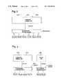
- FIG. 2shows a layer model of the transmission protocols
- FIGS. 3 , 4show data for various services mapped onto common physical channels
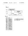
- FIG. 5shows a table containing a mapping specification for services with high data rate dynamics
- FIG. 6shows data transmission in frames with in-band signaling.
- the mobile radio system shown in FIG. 1 as an example of a radio communication systemcomprises a multiplicity of mobile switching centers MSC which are interlinked and set up access to a landline network PSTN.
- these mobile switching centers MSCare connected to at least one respective device RNM for controlling the transmission resources.
- Each of these devices RNMpermits, in turn, a connection to at least one base station BS and represents means which divide services 5 into two classes on the basis of individual service data rate dynamics.
- a base station BScan set up a connection to subscriber stations, e.g. for mobile stations MS or other mobile and stationary terminals, via a radio interface. Each base station BS forms at least one radio cell.
- FIG. 1shows connections for transmitting useful information between a base station BS and mobile stations MS.
- data for, by way of example, three services S(S 1 , S 2 , S 3 )are transmitted within one or more physical channels Phy CH, and signaling information, is transmitted via a monitoring channel FACH (Forward Link Access Channel) which accompanies the connection.
- FACHForward Link Access Channel
- An operation and maintenance center OMCprovides monitoring and maintenance functions for the mobile radio system or for parts thereof.
- the functional scope of this structurecan be transferred to other radio communication systems in which the invention can be used, in particular for subscriber access networks with wireless subscriber access.
- both the base stations BS and the mobile stations MSare provided with data transmission means, and signaling means which communicate with one another.
- the data transmission meansare used for transmitting data for a combination of a plurality of services S via the currently available common physical channels Phy CH.
- the signaling meansFor services S 1 , S 2 with high data rate dynamics, the signaling means signal the transport format TF in-band, and for services S 3 with low data rate dynamics, the signaling means signal the transport format TF in the separate channel FACH.
- the layer model shown in FIG. 2shows the protocols of the radio communication system divided into three layers.
- Layer 1physical layer for describing all the functions for bit transmission via a physical medium (e.g. coding, modulation, transmission power monitoring, synchronization etc.),
- Layer 2data link layer for describing the mapping of data onto the physical layer, and monitoring thereof
- Layer 3network layer for controlling the resources of the radio interface.
- Layer 3stipulates the TFCS for a connection, while layer 2 selects a combination (of a TFC) which is signaled in-band and in a separate channel using a TFCI, as shown later.
- the parameter exchange between Layers 1 and 2supports the functions of transferring frames with data for Layer 2 via the radio interface and of displaying the status of Layer 1 to higher layers.
- the parameter exchange between Layers 1 and 3supports monitoring of the configuration of the transmission in Layer 1 and generates system information relating to Layer 1.
- mapping of the data for various connections S onto a common physical channel Phy CHcorresponds to the interaction of Layers 1 and 2.
- transport formats TFneed to be signaled for currently transmitted services.
- FIG. 3shows, as an illustration of function, a coding and multiplex unit which maps data from a plurality of data channels DCH (which each correspond to the data for a service S 1 , S 2 , S 3 ) onto a coded common transport channel CCTrCH.
- mappingis a specification governing the bit pattern which is to be used for entering the data into a serial data sequence.
- a demultiplexing/allocation meansdistributes the data for the coded common transport channel CCTrCH over a plurality of physical channels Phy CH.
- the physical channels Phy CHare thus always used to transmit data for a plurality of services S 1 , S 2 , S 3 in each case.
- a physical channel Phy CHis not allocated to one service S 1 , S 2 or S 3 alone, but rather is allocated to the coded common transport channel CCTrCH with all its services S 1 , S 2 , S 3 .
- FIG. 4shows the mapping in a slightly modified form, with it becoming clearer that the partial information item TFCI need be signaled only when physical channels Phy CH are jointly used by a plurality of services S 1 , S 2 , S 3 . If a service S 1 or S 2 or S 3 uses one physical channel Phy CH exclusively, then signaling of the partial information item TFCI can be dispensed with.
- standard signalingis not chosen for all services, but instead the services S are distinguished by services S 1 , S 2 with high data rate dynamics and a service S 3 with low data rate dynamics.
- S 1 and S 2are two data services, e.g. S 1 is a video transmission and S 2 is an Internet link.
- S 3may be voice transmission.
- the classification of the services into one of the two classesis stipulated at the start of a connection, but may be changed during the connection. Such a change is made if the number of services changes and hence in-band signaling capacity becomes free or necessary, or if the character of a service changes in terms of the data rate dynamics.
- the permitted transport formats TFare stipulated as shown in FIG. 5 .
- Voice transmissionis distinguished only by two data rates (basic data rate 16 kbit/s or no data transmission, or pause in speech).
- Four different transport formats TFare available for each of the two services S 1 , S 2 .
- the transport format TF 30 , TF 31 for the service S 3is transmitted separately from the physical channels Phy CH for data transmission, in a rapid monitoring channel FACH accompanying the connection. Since the changes in the data rate are rather uncommon, hardly any transmission capacity is lost if the signaling takes somewhat longer.
- the transport formats TF for the services S 1 , S 2are coded in accordance with the table in FIG. 5 . Since a total of 32 combinations of the various transport formats TF are possible for the three services S 1 , S 2 , S 3 , 5 bits would be needed, in binary representation, to code this information item. In accordance with FIG. 5 , however, only 4 bits are necessary, since the current transport format TF 30 or TF 31 for S 3 is signaled separately.
- the 4 bits of the signaling for S 1 and S 2are transmitted in-band.
- capacityis also provided for transmitting the currently chosen combination of the transport formats in the form of the partial information item TFCI.
- a frameIn FDD mode, a frame lasts 10 ms, with bits of a pilot sequence (pilot) being used for channel estimation, bits (pc) being required for transmission power regulation, and bits being reserved for in-band signaling of the TFCI. There is then a data component data containing useful information.
- Error protection coding of the TFCI on 32 bits, for example, and scrambling of the useful information over a plurality of framesare not shown in FIG. 6 .
- the description of the chosen transport formatsapplies for one transmission direction. In a connection, data can naturally be transmitted in both transmission directions (UL upward direction from the mobile station MS to the base station BS, and DL downward direction from the base station BS to the mobile station MS), and different transport formats TF can be stipulated for the data rates in an entirely asymmetrical and appropriate manner.
Landscapes
- Engineering & Computer Science (AREA)
- Computer Networks & Wireless Communication (AREA)
- Signal Processing (AREA)
- Mobile Radio Communication Systems (AREA)
- Time-Division Multiplex Systems (AREA)
- Communication Control (AREA)
Abstract
Description
Claims (23)
Applications Claiming Priority (2)
| Application Number | Priority Date | Filing Date | Title |
|---|---|---|---|
| DE19855194ADE19855194C2 (en) | 1998-11-30 | 1998-11-30 | Method and communication system for the transmission of data of a combination of several services via shared physical channels |
| PCT/DE1999/003742WO2000033601A2 (en) | 1998-11-30 | 1999-11-25 | Communications method and system for transmitting data via physical channels which are used in common |
Publications (1)
| Publication Number | Publication Date |
|---|---|
| US7106705B1true US7106705B1 (en) | 2006-09-12 |
Family
ID=7889495
Family Applications (1)
| Application Number | Title | Priority Date | Filing Date |
|---|---|---|---|
| US09/856,424Expired - LifetimeUS7106705B1 (en) | 1998-11-30 | 1999-11-25 | Method and communications systems for transmitting data for a combination of several services via jointly used physical channels |
Country Status (4)
| Country | Link |
|---|---|
| US (1) | US7106705B1 (en) |
| EP (1) | EP1135892B1 (en) |
| DE (2) | DE19855194C2 (en) |
| WO (1) | WO2000033601A2 (en) |
Cited By (5)
| Publication number | Priority date | Publication date | Assignee | Title |
|---|---|---|---|---|
| US20030069020A1 (en)* | 2001-07-06 | 2003-04-10 | Ipwireless, Inc. | System and method for physical shared channel allocation in a wireless communication system |
| US20050227698A1 (en)* | 2004-03-25 | 2005-10-13 | Katsuya Nonin | Radio communication system and base station thereof |
| US20070133497A1 (en)* | 2003-03-25 | 2007-06-14 | Jani Vare | Transmission parameter information |
| USRE45800E1 (en)* | 2001-07-06 | 2015-11-10 | Sony Corporation | System and method for physical shared channel allocation in a wireless communication system |
| WO2018130306A1 (en)* | 2017-01-13 | 2018-07-19 | Huawei Technologies Co., Ltd. | Quality of service class indicator structure and corresponding controllers and control methods |
Families Citing this family (5)
| Publication number | Priority date | Publication date | Assignee | Title |
|---|---|---|---|---|
| DE19856834C2 (en) | 1998-12-09 | 2002-02-28 | Siemens Ag | Method for data transmission in a radio communication system and radio communication system for data transmission |
| US6889050B1 (en)* | 2000-11-22 | 2005-05-03 | Telefonaktiebolaget Lm Ericsson (Publ) | Variable transmission rate services in a radio access network |
| CN1129297C (en) | 2000-12-14 | 2003-11-26 | 华为技术有限公司 | Multiple-service combination transmission method |
| DE10124765A1 (en) | 2001-05-21 | 2002-11-28 | Siemens Ag | Arrangement of communication channels in a mobile telecommunication system |
| DE102004021070B4 (en)* | 2004-04-29 | 2006-07-13 | Infineon Technologies Ag | Communication system comprising a communication network, base station, user equipment and method for processing data |
Citations (17)
| Publication number | Priority date | Publication date | Assignee | Title |
|---|---|---|---|---|
| US3936609A (en)* | 1974-02-14 | 1976-02-03 | Gte Automatic Electric Laboratories Incorporated | Submultiplex transmission of alarm status signals for a time division multiplex system |
| US4868811A (en) | 1987-03-10 | 1989-09-19 | Kabushiki Kaisha Toshiba | Multiple access communication system |
| US5136612A (en)* | 1990-12-31 | 1992-08-04 | At&T Bell Laboratories | Method and apparatus for reducing effects of multiple access interference in a radio receiver in a code division multiple access communication system |
| US5157660A (en) | 1989-09-25 | 1992-10-20 | Hitachi, Ltd. | Communication system including portable terminals and fixed terminals |
| US5257283A (en) | 1989-11-07 | 1993-10-26 | Qualcomm Incorporated | Spread spectrum transmitter power control method and system |
| US5313461A (en)* | 1989-10-19 | 1994-05-17 | Inventahl Ab | Method and device in a digital communication network |
| US5469431A (en)* | 1993-07-12 | 1995-11-21 | Philips Electronics North America Corp. | Method of and apparatus for channel mapping with relative service identification |
| US5592469A (en)* | 1993-08-28 | 1997-01-07 | Alcatel Sel A.G. | Radio system |
| EP0854596A1 (en) | 1997-01-21 | 1998-07-22 | Nokia Mobile Phones Ltd. | Apparatus and method for configuring a data channel for symmetric/asymmetric data transmission |
| US5822309A (en)* | 1995-06-15 | 1998-10-13 | Lucent Technologies Inc. | Signaling and control architecture for an ad-hoc ATM LAN |
| US5844895A (en)* | 1995-06-30 | 1998-12-01 | Siemens Aktiengesellschaft | ATM communications network |
| US5953338A (en)* | 1996-12-13 | 1999-09-14 | Northern Telecom Limited | Dynamic control processes and systems for asynchronous transfer mode networks |
| US6018528A (en)* | 1994-04-28 | 2000-01-25 | At&T Corp | System and method for optimizing spectral efficiency using time-frequency-code slicing |
| US6122759A (en)* | 1995-10-10 | 2000-09-19 | Lucent Technologies Inc. | Method and apparatus for restoration of an ATM network |
| US6205143B1 (en)* | 1996-03-14 | 2001-03-20 | Telefonaktiebolaget L M Ericsson | System supporting variable bandwidth asynchronous transfer mode network access for wireline and wireless communications |
| US6636497B1 (en)* | 1998-11-30 | 2003-10-21 | Nokia Networks Oy | Air interface capacity scheduling method |
| US6678527B1 (en)* | 1998-02-09 | 2004-01-13 | Nokia Networks Oy | Multimedia and multiservice calls in mobile network |
- 1998
- 1998-11-30DEDE19855194Apatent/DE19855194C2/ennot_activeExpired - Fee Related
- 1999
- 1999-11-25USUS09/856,424patent/US7106705B1/ennot_activeExpired - Lifetime
- 1999-11-25WOPCT/DE1999/003742patent/WO2000033601A2/enactiveIP Right Grant
- 1999-11-25EPEP99964381Apatent/EP1135892B1/ennot_activeExpired - Lifetime
- 1999-11-25DEDE59914681Tpatent/DE59914681D1/ennot_activeExpired - Lifetime
Patent Citations (17)
| Publication number | Priority date | Publication date | Assignee | Title |
|---|---|---|---|---|
| US3936609A (en)* | 1974-02-14 | 1976-02-03 | Gte Automatic Electric Laboratories Incorporated | Submultiplex transmission of alarm status signals for a time division multiplex system |
| US4868811A (en) | 1987-03-10 | 1989-09-19 | Kabushiki Kaisha Toshiba | Multiple access communication system |
| US5157660A (en) | 1989-09-25 | 1992-10-20 | Hitachi, Ltd. | Communication system including portable terminals and fixed terminals |
| US5313461A (en)* | 1989-10-19 | 1994-05-17 | Inventahl Ab | Method and device in a digital communication network |
| US5257283A (en) | 1989-11-07 | 1993-10-26 | Qualcomm Incorporated | Spread spectrum transmitter power control method and system |
| US5136612A (en)* | 1990-12-31 | 1992-08-04 | At&T Bell Laboratories | Method and apparatus for reducing effects of multiple access interference in a radio receiver in a code division multiple access communication system |
| US5469431A (en)* | 1993-07-12 | 1995-11-21 | Philips Electronics North America Corp. | Method of and apparatus for channel mapping with relative service identification |
| US5592469A (en)* | 1993-08-28 | 1997-01-07 | Alcatel Sel A.G. | Radio system |
| US6018528A (en)* | 1994-04-28 | 2000-01-25 | At&T Corp | System and method for optimizing spectral efficiency using time-frequency-code slicing |
| US5822309A (en)* | 1995-06-15 | 1998-10-13 | Lucent Technologies Inc. | Signaling and control architecture for an ad-hoc ATM LAN |
| US5844895A (en)* | 1995-06-30 | 1998-12-01 | Siemens Aktiengesellschaft | ATM communications network |
| US6122759A (en)* | 1995-10-10 | 2000-09-19 | Lucent Technologies Inc. | Method and apparatus for restoration of an ATM network |
| US6205143B1 (en)* | 1996-03-14 | 2001-03-20 | Telefonaktiebolaget L M Ericsson | System supporting variable bandwidth asynchronous transfer mode network access for wireline and wireless communications |
| US5953338A (en)* | 1996-12-13 | 1999-09-14 | Northern Telecom Limited | Dynamic control processes and systems for asynchronous transfer mode networks |
| EP0854596A1 (en) | 1997-01-21 | 1998-07-22 | Nokia Mobile Phones Ltd. | Apparatus and method for configuring a data channel for symmetric/asymmetric data transmission |
| US6678527B1 (en)* | 1998-02-09 | 2004-01-13 | Nokia Networks Oy | Multimedia and multiservice calls in mobile network |
| US6636497B1 (en)* | 1998-11-30 | 2003-10-21 | Nokia Networks Oy | Air interface capacity scheduling method |
Non-Patent Citations (4)
| Title |
|---|
| ESTI STC SMG2#28 T doc 515/98 "Vocabulary Used in Radio Interface Protocol Specifications" Draft, Version0.20, Nov. 16, 1998 Dresden, Germany. |
| ETSI SMG2/UMTS L23 Tdoc 357/98 expert group Layer1-General Requirememts Oct. 6, 1998 Milan, Italy. |
| ETSI STC SMG2#28 Tdoc 508/98 "UE-UTRAN Radio Interface Protocol Architecture" Stage2, Nov. 16, 1998 Dresden, Germany. |
| The GSM SYSTEM "The Radio Interface" XP-002137738 98/5843 p. 190-191. |
Cited By (8)
| Publication number | Priority date | Publication date | Assignee | Title |
|---|---|---|---|---|
| US20030069020A1 (en)* | 2001-07-06 | 2003-04-10 | Ipwireless, Inc. | System and method for physical shared channel allocation in a wireless communication system |
| US7480261B2 (en)* | 2001-07-06 | 2009-01-20 | Ipwireless, Inc. | System and method for physical shared channel allocation in a wireless communication system |
| USRE45800E1 (en)* | 2001-07-06 | 2015-11-10 | Sony Corporation | System and method for physical shared channel allocation in a wireless communication system |
| US20070133497A1 (en)* | 2003-03-25 | 2007-06-14 | Jani Vare | Transmission parameter information |
| US8792596B2 (en)* | 2003-03-25 | 2014-07-29 | Nokia Corporation | Transmission parameter information |
| US20050227698A1 (en)* | 2004-03-25 | 2005-10-13 | Katsuya Nonin | Radio communication system and base station thereof |
| US7751824B2 (en)* | 2004-03-25 | 2010-07-06 | Kabushiki Kaisha Toshiba | Radio communication system and base station thereof |
| WO2018130306A1 (en)* | 2017-01-13 | 2018-07-19 | Huawei Technologies Co., Ltd. | Quality of service class indicator structure and corresponding controllers and control methods |
Also Published As
| Publication number | Publication date |
|---|---|
| EP1135892B1 (en) | 2008-03-05 |
| WO2000033601A2 (en) | 2000-06-08 |
| EP1135892A2 (en) | 2001-09-26 |
| DE19855194A1 (en) | 2000-06-08 |
| DE59914681D1 (en) | 2008-04-17 |
| WO2000033601A3 (en) | 2000-08-10 |
| DE19855194C2 (en) | 2001-06-13 |
Similar Documents
| Publication | Publication Date | Title |
|---|---|---|
| US7088697B1 (en) | Methods and apparatus for transmitting data in a radio communication system including signaling allocation of a common channel | |
| CA2289857C (en) | Method and apparatus for formatting synchronous and asynchronous data | |
| CA2345823C (en) | Rendering multicast service with sufficient reception quality to wireless terminals | |
| US7822420B1 (en) | Method and base station for allocating a channel required for a radio transmission | |
| EP1388224B1 (en) | Physical channel configuration signaling procedures | |
| AU4619799A (en) | Method and system for testing data channel functionality in a radio apparatus | |
| US7106705B1 (en) | Method and communications systems for transmitting data for a combination of several services via jointly used physical channels | |
| KR101493794B1 (en) | Method and apparatus for a spectrally compliant cellular communication system | |
| WO2000033516A1 (en) | Method and communications system for transmitting data for a combination of several services via jointly used physical channels | |
| US7324477B2 (en) | Method for allocating channels in a radio communications system | |
| KR100516632B1 (en) | The algorithm of the data transmission in high data rate system | |
| WO1999035870A1 (en) | Method for allocating channels | |
| JP3189204B2 (en) | Channel configuration method of inter-station transmission line in mobile communication system | |
| US20040081130A1 (en) | Communication system | |
| HK1065902B (en) | The method and device for minimizing the amount of data necessary to signal code and timeslot assignments |
Legal Events
| Date | Code | Title | Description |
|---|---|---|---|
| AS | Assignment | Owner name:SIEMENS AKTIENGESELLSCHAFT, GERMANY Free format text:ASSIGNMENT OF ASSIGNORS INTEREST;ASSIGNORS:MECKLENBRAUKER, CHRISTOPH;BENZ, MICHAEL;KLEIN, ANJA;AND OTHERS;REEL/FRAME:011894/0540;SIGNING DATES FROM 20010123 TO 20010501 | |
| STCF | Information on status: patent grant | Free format text:PATENTED CASE | |
| FEPP | Fee payment procedure | Free format text:PAYOR NUMBER ASSIGNED (ORIGINAL EVENT CODE: ASPN); ENTITY STATUS OF PATENT OWNER: LARGE ENTITY | |
| FPAY | Fee payment | Year of fee payment:4 | |
| FPAY | Fee payment | Year of fee payment:8 | |
| MAFP | Maintenance fee payment | Free format text:PAYMENT OF MAINTENANCE FEE, 12TH YEAR, LARGE ENTITY (ORIGINAL EVENT CODE: M1553) Year of fee payment:12 | |
| AS | Assignment | Owner name:IP EDGE LLC, TEXAS Free format text:ASSIGNMENT OF ASSIGNORS INTEREST;ASSIGNOR:SIEMENS AKTIENGESELLSCHAFT;REEL/FRAME:047686/0465 Effective date:20181020 | |
| AS | Assignment | Owner name:SONOHM LICENSING LLC, TEXAS Free format text:ASSIGNMENT OF ASSIGNORS INTEREST;ASSIGNOR:IP EDGE LLC;REEL/FRAME:050362/0490 Effective date:20190820 |